Kondo Kagaku T39EX2 Radio control transmitter User Manual EX 2 manual En 0530
Kondo Kagaku Co., Ltd. Radio control transmitter EX 2 manual En 0530
Contents
- 1. 06_1_Users_Manual_rev1
- 2. 06_2_Users_Manual_rev1
- 3. 06_3_Users_Manual_rev1
06_1_Users_Manual_rev1

INSTRUCTION MANUAL
KONDO KAGAKU Co., Ltd. 2015 Ver.1.0

2
Title Title
Page Page
■ Table of Contents ※ Click the page number to jump to that page.
■ Table of Contents 2
■ For Safe Operation 3
■ Getting Started 5
●Transmitter Assembly 5
●Transmitter Dismantling 5
■ Names of Parts 6
●ET Keys (1-5) and BT Button (1) 7
●Steering Adjustment 7
●Wheel Cap Removal 7
●Throttle Adjustment 7
●Throttle Position Adjustment 7
●Colored Grip and Pad Replacement 7
●Unit Connector 8
●Power Switch 8
■ Preparations 9
●Battery Installation 9
●Battery Level Warning 9
● Initializing EX-2 10
●How to change the Modulation 10
●Countermeasures Against Noise 11
●Receiver Installation 12
●Pairing (For general receiver) 13
●Pairing (For MHS Mini-Z) 14
●Fail-Safe Setting 15
■ Procedures Prior to Operation 16
●Trim and Sub Trim Operation 17
■ Operating procedure 18
●STEERING 18
●THROTTLE 19
●3CH 4CH operation 20
■
Display and Control Method for attaching the Xpansion unit
21
●Basic Operations to Change Settings 21
●How to attach Xpansion unit 22
●Startup Screen and Initial Screen 23
●VR information setting 24
●How to change the Modulation mode 24
●Pairing (For general receiver) 25
●Pairing (For MHS Mini-Z) 26
■TOP MENU 27
■□□ FUNCTION 29
● Model Menu (Model) 29
▶Model Select (MDL-Select) 29
▶Model Name (MDL-Name) 29
▶Model Copy (MDL-Copy) 30
▶Model Reset (MDL-Reset) 30
● TIMER MENU 31
▶TRGSTART (Trigger Start) 31
▶LAP HISTORY (Lap History) 31
▶ALARM (Alarm) 31
●KEYSET (Key setting MENU) 32
●3・4CH (3・4Channel) 33
▶2WAY(2WAY) 33
▶3WAY(3WAY) 33
▶5WAY(5WAY) 34
▶ANALOG (Analog mixing MENU) 34
▶GYRO (GYRO mixing MENU) 34
▶TWIN SERVO (Twin servo mixing MENU) 35
▶4WS (4WS mixing MENU) 35
▶AMP (AMP mixing MENU) 36
▶T-MIX (Throttle mixing MENU) 37
●TRIM SET (Trim SET MENU) 38
▶STEER AUTO TRIM (Steering auto trim) 38
▶STEER AUTO BALANCE
(Steering auto balance Left)
38
▶STEER AUTO BALANCE
(Steering auto balance Right)
38
●SYSTEM MENU 39
▶DISPLAY MENU 39
▶BATTERY TYPE 39
!WARNING! Warning Display 40
▶CALCULATOR 41
▶SOUND MENU 41
▶VR INFORMATION Volume information 41
▶KEYSPEED 42
▶OPERATIN ALARM 42
□■□STEERING MENU 43
●TRAVEL MENU 43
▶ST TRAVEL Steering Travel 43
▶ST BALANCE L R Seering Balance L R 43
●TRIM MENU 44
▶ST TRIM Steering Trim 44
▶ST SUBTRIM Steering Subtrim 44
▶ST TRIMRATE Steering Trimrate 44
●ST SPEED Steering Speed 45
▶ST TURN Steering Turn Speed 45
▶ST RETURN Steering Return Speed 45
●DYNAMC Steering Dynamics 46
▶CURVE Steering curve 46
▶PUNCH Steering punch 46
●FEEL MENU 47
▶ST FEEL Steering feel MENU 47
●REVERSE Steering Reverse 47
▶ST REVERSE Steering Reverse 47
□□■THROTTLE MENU 48
●TRAVEL Throttle travel 48
▶TH TRAVEL F Throttle Travel F 48
▶TH TRAVEL B Throttle Travel B 48
●TRIM MENU 49
▶TH TRIM Throttle Trim 49
▶TH SUBTRIM Throttle Subtrim 49
▶TH TRIMRATE Throttle Trimrate 49
●TH SPEED Throttle Speed 50
▶TH TURN Throttle Turn Speed 50
▶TH RETURN Throttle Return Speed 50
●DYNAMC Throttle Dynamics 51
▶CURVE Throttle Curve 51
▶PUNCH Throttle punch 51
●FEEL Throttle feel MENU 52
▶TH FEEL Throttle feel 52
●OVERRIDE Throttle Override 53
●REVERSE Throttle Reverse 53
▶TH REVERSE Throttle Reverse 53
●CYCLE Throttle Cycle 54
▶ACCEL Throttle Acceleration 54
▶ABS Throttle ABS 54
●ATSTART Throttle Auto-Start 55
●OFFSET Throttle OFFSET 56
■ Glossary 57
■ Repair policy 60
■ Specications 61

Due to the nature of radio controlled models, improper handling may lead to dangerous situations. Therefore please
read the following information carefully in order to ensure safe operation. Please also understand that KO Propo is
not responsible for any injuries or damage which result from noncompliance of these cautions and notices.
●When Installing Components
●Notes for Usage
●Make sure metal parts on the model (car chassis/ship hull) do not come into contact
with each other.
※Contact between metal parts may result in noise, which could cause the receiver to
malfunction and lead to an uncontrollable model.
●Do not cut or bundle the antenna cable.
※This may lower the receiver's sensitivity and lead to an uncontrollable model.
●Ensure correct polarity when installing transmitter and receiver batteries.
※Incorrect polarity may damage the product.
●Within Japan, this product is limited to usage with models which operate on the
ground or in the water.
※Do not use for other non-designated purposes.
●Ensure that all connectors (receiver, servo, switch, etc.) are connected securely.
※If connections become loose due to vibrations, it may lead to an uncontrollable model.
●Securely attach receiver with thick double-sided tape and ensure that it does not
make contact with other parts.
※Strong shocks or contact with other parts due to vibrations may lead to an
uncontrollable model.
●Check servo operation to ensure the pushrod is not subject to excessive loads.
※Excessive loads may damage the servo or increase battery power consumption.
●Make sure to use the rubber grommet when attaching the servo and that the servo
does not contact the R/C equipment tray.
※If vibrations affect the servo, it may lead to damage or an uncontrollable model.
●Use in conjunction with genuine official KO Propo products.
※KO Propo is not responsible for any damages or injuries which result from use of this
product in combination with other manufacturer's products.
●Do not use when there is thunder.
※It is possible for lightning to strike the antenna.
●Do not use in the rain or in areas where water has accumulated.
※If water enters the product it may lead to an uncontrollable model.
●Do not use in the following locations:
1. Near R/C circuits (within 3km)
2. Near crowds, on streets, or near actual vehicles or ships.
3. Near high-voltage power lines or communication facilities.
※If signal interference, etc. causes an uncontrollable model, a serious accident may
result.
●Do not use when your concentration levels are compromised by tiredness, alcohol,
medication, etc.
※Mistakes in judgment may result in serious accidents.
●Do not allow glow engine fuel or engine exhaust to contact the product.
※These may attack the plastic and damage the product.
●Check to ensure that the selected model memory matches the model to be controlled.
※Using an incorrect memory may lead to an uncontrollable model.
●Make sure to stop the engine (disconnect motor cables) before changing transmitter
settings.
Warning! Improper handling/
usage may lead to a high probability of material damage as well as a possibility of
serious personal injury or even death.
Notice! Improper handling/
usage may lead to personal injury or material damage.
Warning!
Enforcement matters
Warning!
Prohibited matters
Warning!
Prohibited matters
Warning!
Enforcement matters
3
■ For Safe Operation
●Notes After Usage
●
Transmitter Battery Handling and Charging (separately available option)
Caution!
Enforcement matters
Caution!
Enforcement matters
Danger!
Enforcement matters
Danger!
Enforcement matters
●Do not touch engine, motor, ESC, etc. immediately after use as they may be hot.
※Doing so may lead to burns.
●When switching on, always turn on the transmitter first, followed by the receiver.
Follow the reverse order when switching off.
※If the wrong order is followed, it may lead to an uncontrollable model.
●Dismantling or modifying the RF Module (internalized in the case of the EX-2) is
prohibited and is punishable by law.
※Doing so may lead to accidents such as short circuits and KO Propo Customer
Service Department may not accept dismantled/modified products for repair.
●Do not use this product in aircraft, hospitals, or near fire alarms or medical equipment.
※This may lead to malfunctions and result in serious accidents. Also, by law you must
cease operation if the product affects other wireless or electrical devices.
●2.4GHz transmitters must be registered with the Japan Radio Control Safety
Association.
※The transmitter which you have purchases is already registered. Products which do
not have proof of registration are illegal.
●In the case of an R/C car, make sure to remove the battery pack after driving.
※If the car is switched on accidentally, it may lead to a fire or an uncontrollable model.
●Keep transmitters, batteries, and models away from small children.
※Chemical agents and the items themselves may cause personal injury.
●Remove batteries from transmitter if it will not be used for a considerable time.
※If batteries are left in the transmitter, battery leakage may result in damage.
●Do not store transmitter/receiver in the following conditions:
1. Extremely hot (over 40ºC) or cold (below 10ºC) temperatures.
2. Locations in direct sunlight.
3. Locations with high humidity.
4. Locations subject to vibrations.
5. Locations with lots of dust.
※These conditions may cause the case to deform and damage the product.
●Never short-circuit the battery connector.
※This may lead to a fire or explosion.
●Do not dispose batteries in fires.
※This is very dangerous and may lead to an explosion.
●Use KO Propo chargers to charge the battery and use the correct current (under 1A).
※Incorrect current may lead to battery damage, overheating, or leakage.
※Other manufacturer's chargers may not have a automatic cutoff function.
●Do not subject the battery to strong shocks.
※This may damage the battery and cause leakage or a short circuit.
●Do not dismantle or modify the battery.
※This may cause dangerous leakage of battery fluids.
●Keep away from water. Do not charge a wet battery.
※This may cause overheating and damage.
●Do not charge alkaline batteries.
※Alkaline and other single-use batteries cannot be recharged. Doing so may lead to fire
and damage.
●Do not use wet hands when plugging in the charger's AC Adapter.
※This may result in electrical shocks.
※If there is battery fluid leakage, avoid contact with eyes as it may result in blindness. If contact
with eyes occur, flush with large amounts of water and seek medical attention immediately.
※When disposing batteries, Ni-Cd, Ni-MH, Li-Po, and Li-Fe batteries should be recycled in order to
help protect the environment.
Warning!
Enforcement matters
Caution!
Prohibited matters
4
①① ②②
③
③
①① ②②
③③
①①
②
②
5
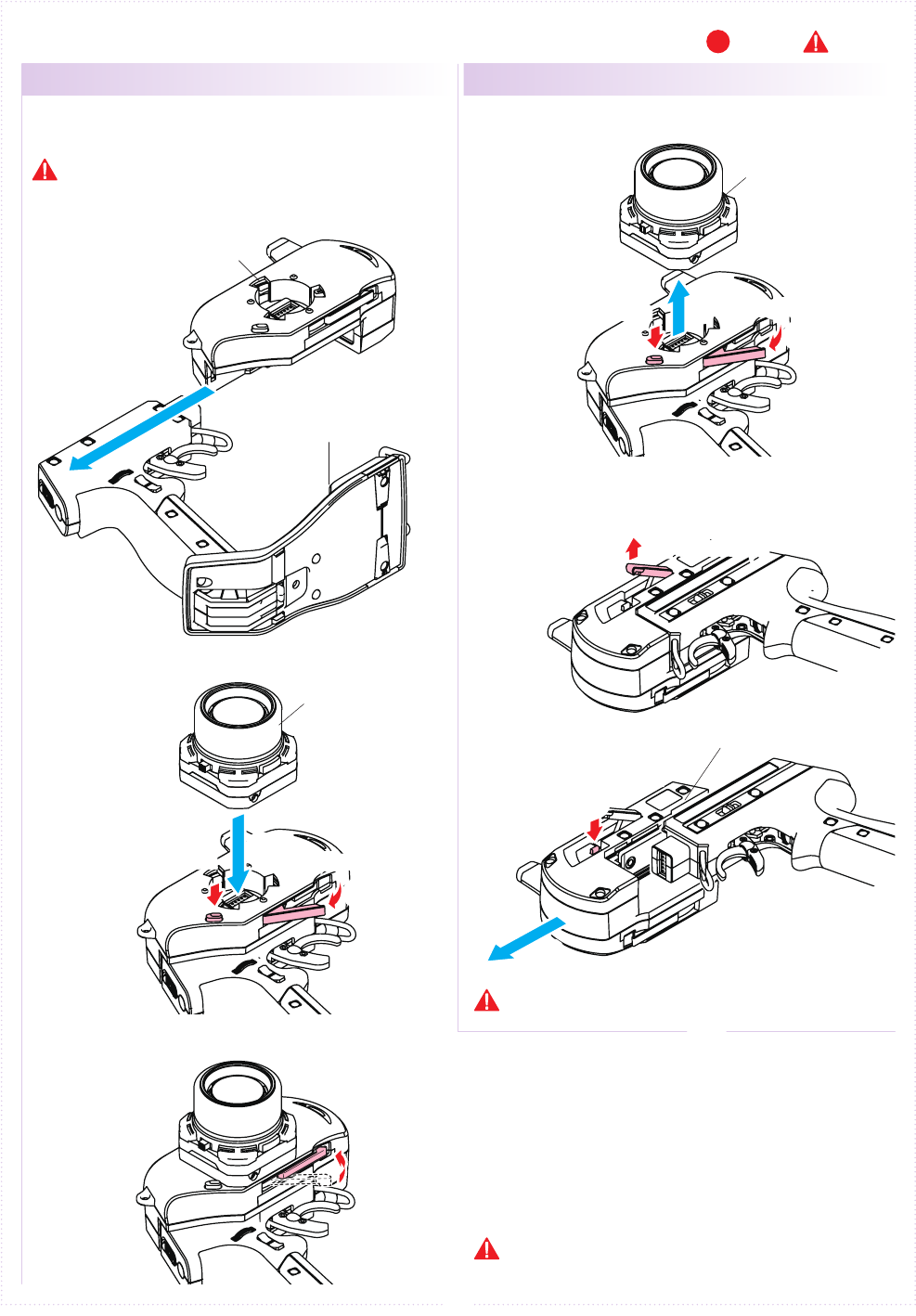
■ Getting Started
Insert the Grip Unit into the Master Unit, then attach
the Steering Unit.
Detach the Steering Unit, then detach the Master
Unit.
● Transmitter Assembly ● Transmitter Dismantling
1.
1.
2.
2.
3.
3.
Remove the connector cover before use.
If storing the transmitter in dismantled form,
please remember to attach the connector covers.
Assembly may dier with the included set contents.
[Legend] P:Point :Notice
Steering Unit Release Button
Steering Unit Release Button
Steering Unit Lock Lever
Steering Unit Lock Lever
Grip Unit Lock Lever
Grip Unit Release Button
Grip Unit
Master Unit
Master Unit
Steering Unit
Steering Unit
6
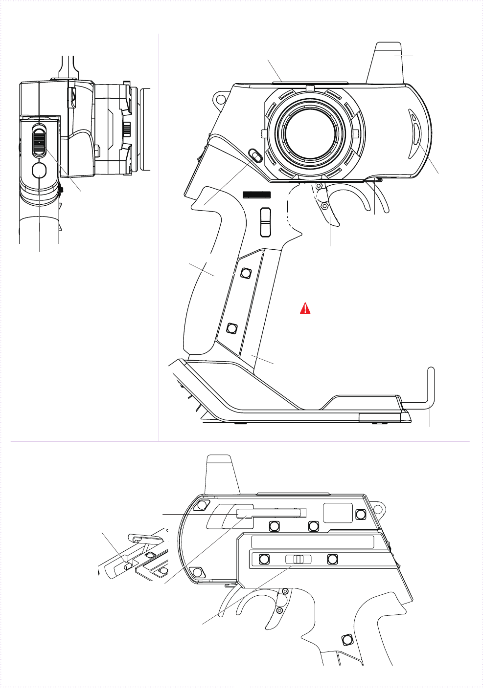
Antenna
EXP Connector Cover
Power Switch(P.8)
Charger Jack(P.8)
LED
Steering Unit
Release Button(P.5)
Colored Grip
(p.7)
Colored Pad(P.7)
● ET Keys (1-5) and BT Button (1)
Functions may be assigned to the
keys/button.
※ Only Expert grip unit available.(No.10526)
There is no ET4/5 keys in the following sets.
No80561EX-2 Standard edition
Guard Bar
Steering Unit
Lock Lever(P.5)
※ Open the cover
(Only Expert Grip)
Throttle Trigger(P.7)
Grip Unit Lock Lever
(P.5)
Grip Unit
Release Button(P.5)
Throttle Trigger
Position Adjuster(P.7)
ET1
(P.7)
BT1
(P.7)
ET2
(P.7)
ET4
(P.7)
ET5
(P.7)
ET3
(P.7)
■ Names of Parts
《Front View》《Side View》
《Rear View》
The possible functions which each key/
button may be assigned to are dierent.
The tabs on the colored grip and pad are to be inserted
into holes. Note the direction.
Make sure the battery box or battery pack is removed
before replacing the colored grip and pad.
Note direction of the of the colored grip and pad
7
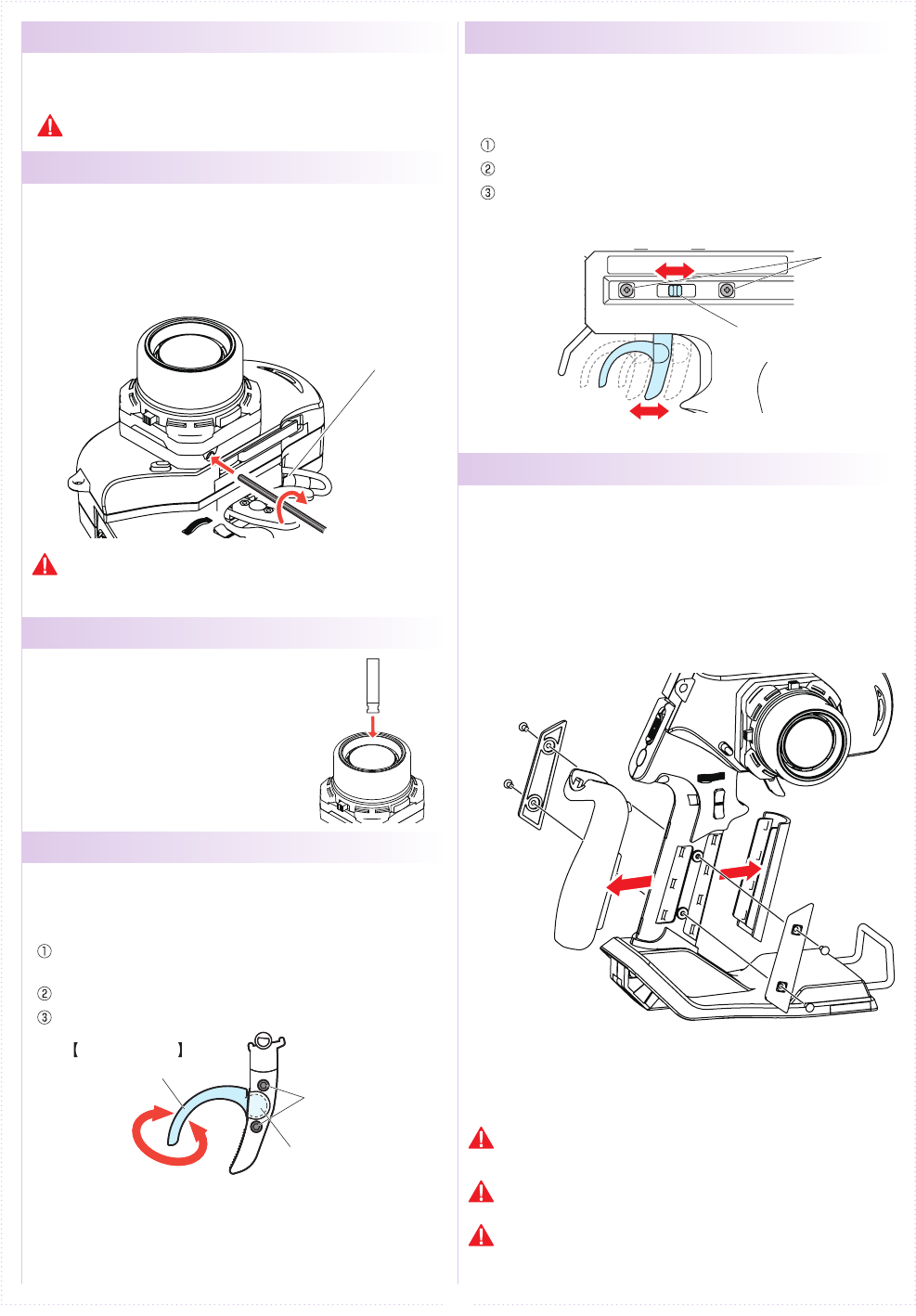
●Steering Wheel Adjustment
●Throttle Trigger Adjustment
●Wheel Cap Remove
●
Throttle Trigger Position Adjustment
●
Colored Grip and Pad Replacement
● ET Keys (1-5) and BT Button (1)
Functions may be assigned to the keys/button.
The possible functions which each key/button may be
assigned to are dierent.
Colored grip pad (optional) and Large/small grip pad
options are available.
Remove the two screws on each side of the grip to
detach the grip plates, then attach the colored grip
and pad.
《How to change》
Adjust the tension of the steering wheel spring.
Insert a 1.5mm hex wrench referring to the image below.
Rotate clockwise to increase tension and counterclockwise to
decrease it.
[How to Adjust]
Hex Wrench
Excessive counterclockwise rotation will result in the wheel being
unable to return to neutral position. In this case, rotate clockwise
until the wheel returns to neutral.
Insert Wheel Cap Remover to the wheel cap spoke.
Pull up Wheel cap remover with Wheel Cap.
Adjust the position and angle of the brake trigger to your
preferences.
Loosen the hex screws on the throttle trigger with a 1.5mm
hex wrench.
Freely adjust the brake trigger position.
Tighten the hex screws to secure.
[How to Adjust]
Throttle Trigger
Brake Trigger Hex Screws
Ball Joint
The position of the throttle trigger may be adjusted to match the
user's hands.
Loosen two screws on the rear side of the transmitter.
Slide the Throttle Trigger Position Adjuster as desired.
Tighten the loosened screws to secure.
[How to Adjust]
Screws
Throttle Trigger
Position Adjuster
8
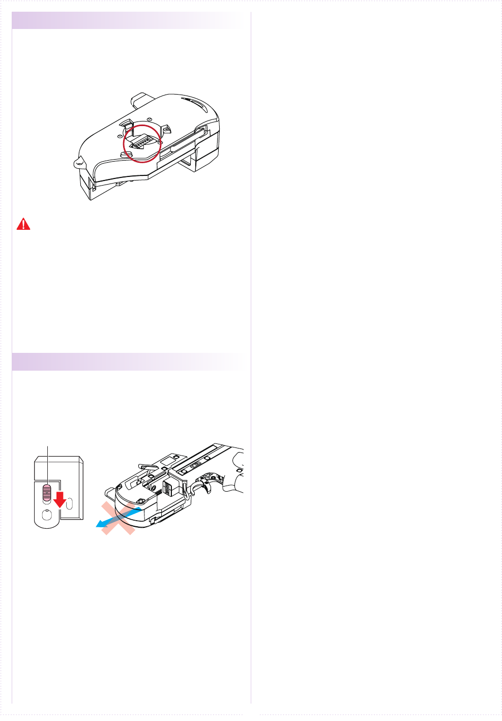
●Unit Connector
●Power Switch
This product may be dismantled and therefore each unit
features their respective connectors. Dirty or damaged
connectors may result in malfunctions, so please handle them
carefully.
Do not touch the unit connectors with your ngers. If connectors
become corroded due to grime, they may become inoperable. If
storing the transmitter in dismantled form. After prolonged use, a
black residue may build up on the connectors. Use cotton swabs
dipped in cleaning alcohol to remove. KO Propo's Customer
Service Department also handles transmitter maintenance.
This product features a safety lock. The Master Unit and Grip
Unit cannot be detached when the Power Switch is in the ON
position. Turn off the transmitter before dismantling.
Power Switch
①①
①
①
②
②
②
②
9
■ Preparations
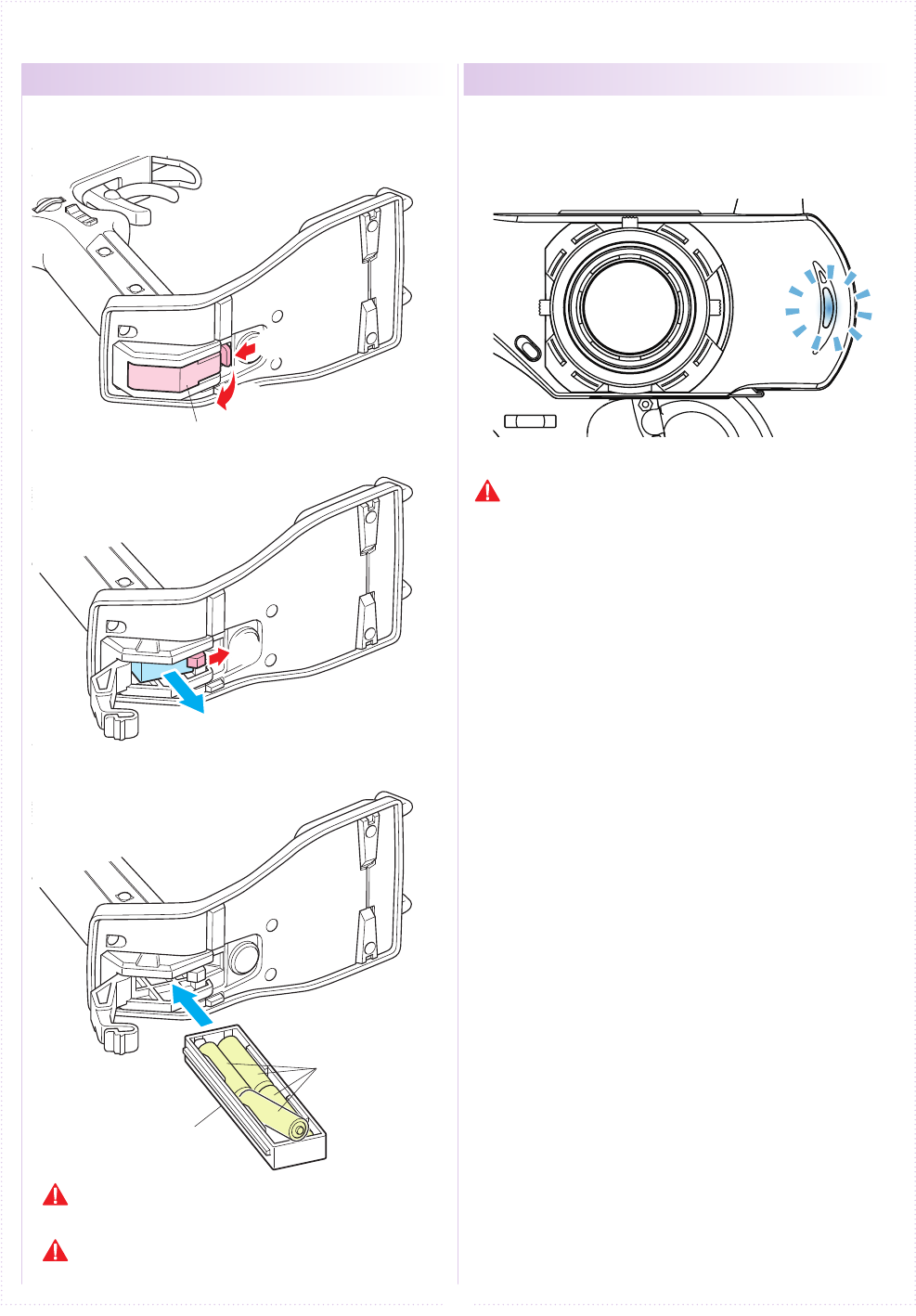
●Battery Installation ● Battery Level Warning
Battery Box
1.
2.
3.
R03/AAA/UM4
Batteries (4pcs.)
Battery Box Cover
Press the tab on the bottom of the transmitter to open
battery box cover.
Remove the lock to pull out battery
box.
Install four R03/AAA/UM4 alkaline
batteries while noting their polarity,
then replace
battery box.
Use batteries which have adequate remaining capacity. Weak
batteries mean lower transmitting power and may result in
malfunctions.
Do not install Ni-Cd or Ni-MH batteries in the battery box.
(These may cause the battery connectors to corrode.)
A warning will be displayed with the LED ashing and
an alarm will sound when battery voltage is less 4v.
When you see this warning, stop your model in a safe
area, turn it o and install new transmitter batteries.
If the Xpansion unit is not assembled or
used, do not use the LiFe/LiPo battery.
10
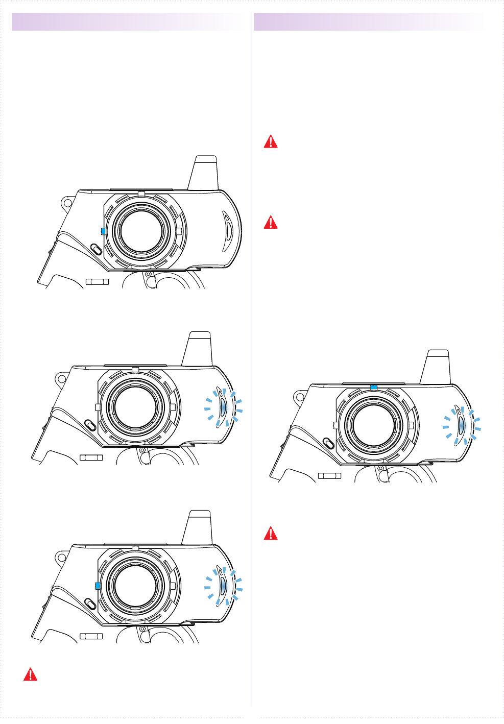
● Initializing EX-2 ●
How to change the Modulation mode
1.
2.
3.
Power on while operating ET2 lever below.
ET2
ET2
Power ON
When using the EX-2 for the rst time, please carry
out the following settings.
※ EX-2 does will not work normally if the initial
conrguration is not set.
※ This is an operation method when the expansion
unit is not assembled.Initialization is necessary
using a dierent method when expansion unit is
put on, see p. 24 for more information.
EX-2 has two Modulation modes.
※ When attaching the Xpansion unit, this operation
is the same.
① Turn o EX-2 switch.
② Push the ET1 lever to the left and power on.
③ Hold ET1 lever until the buzzer sounds and the
LED of EX-2 turns on (approximately two seconds).
④ Set the Fail-Safe Function(p.15).
《Functions》
● General RC models FHSS mode : LEDSolid
Operating the general receivers such as
KR-211FH/KR-241FH
● Mini-Z MHS mode : LED Flashing slowly
Oparating Kyosho Mini-Z MHS mode.
(MR-03 VE PRO)
Hold the ET2 lever until the LED of EX-2 turns
on (approximately two seconds).
After the LED turns on, release ET2 lever.
Buzzer sounds, and reset is completed.
When changing each unit for a different unit, please
perform this initialization again.
The receiver is available for only FHSS
method.The receiver of other methods
(DSSS/27/40MHz) does not work.
Only MiniZ for MHS is available. Does not work with
the receiver for ASF, FHS, general RC cars.
If the pilot LED is blinking fast, this is a warning
that the battery voltage is low. Please change to
new batteries or for a battery pack which has been
charged.
↓
↓
↓
↓
PowerON
↓
↓
↓
ET1
Approximately two seconds,
LED turns on.
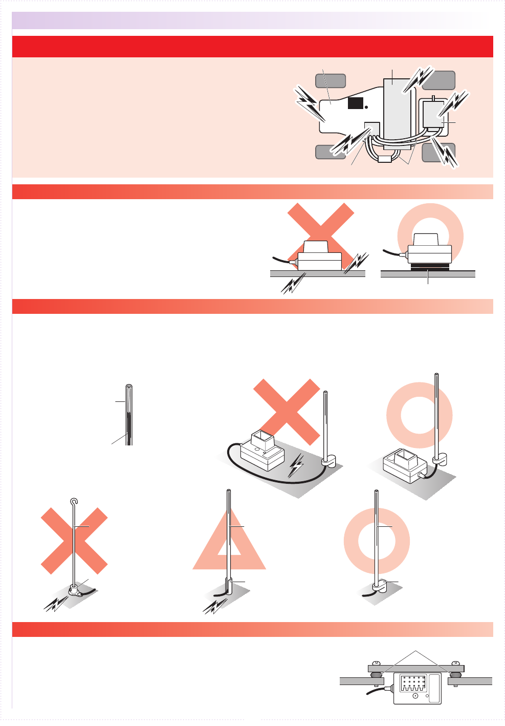
Carbon Fiber Chassis
Noise is generated in any area where a large amount of
electric current is flowing. Position the receiver and
antenna cable as far away from the motor, battery, ESC,
and their associated cables as possible. (Metal or carbon
fiber chassis components will also conduct electricity
and generate noise.)
Since R/C models are controlled via radio signals, taking
appropriate measures against noise generated by
on-board equipment is of utmost importance. Take
adequate measures against noise so that your machine
can fully realize your driving potential.
Battery Pack
Receiver
ESC Silicon Cables
Motor
Noise
Noise
Noise
Noise
Noise
Noise
Noise
Noise
Noise
Noise
Keep antenna cable away from all sources of noise!
When installing the receiver to the chassis or R/C
equipment deck/tray, use two or more pieces of thick
double-sided tape to raise the receiver off the chassis
surface. By increasing the separation between the
receiver and the noise-generating carbon-fiber chassis
components, the effects of noise can be decreased.
Raise the antenna cable vertically from as high a position as possible. Insert the antenna cable into the antenna
pipe so that the tip of the antenna aligns with the end of the pipe. Make the length of cable which runs between
the receiver and the pipe as short as possible and position the antenna holder as close to the receiver as
possible. Position the antenna cable away from sources of noise such as the chassis and R/C equipment
deck/tray. Use an antenna pipe and antenna mount that are made from plastic, since metal parts will conduct
noise.
Engine vibrations may damage the receiver. Make sure to attach a
grommet (receiver holder) to reduce the effects of such vibrations. Do
not attach the receiver directly to the chassis or R/C equipment
deck/tray with double-sided tape. Also position the receiver so that it
does not contact the heat and exhaust of the engine and muffler.
Plastic Antenna Pipe Plastic Antenna Pipe
Plastic Antenna Holder
Grommet
Aluminum Antenna Holder
Aluminum Antenna Holder
Piano Wire
Double-Sided Tape
Antenna Cable
Signal Receiving Section
Noise
Noise
Noise
Noise
Noise
Noise
Noise
Noise
Noise
Noise
(Acceptable with FRP
or plastic chassis)
Soldered Lug Plate
● Receiver Installation on a Carbon Fiber Chassis
● Antenna Installation
● Installing Onto a Glow Engine Car
※Install the receiver so that its LEDs are visible.
※Install the receiver so that its LEDs are visible.
※Do not bend or cut the antenna cable.
(This may break the antenna wire and deteriorate its
performance.)
11
● Countermeasures Against Noise
12
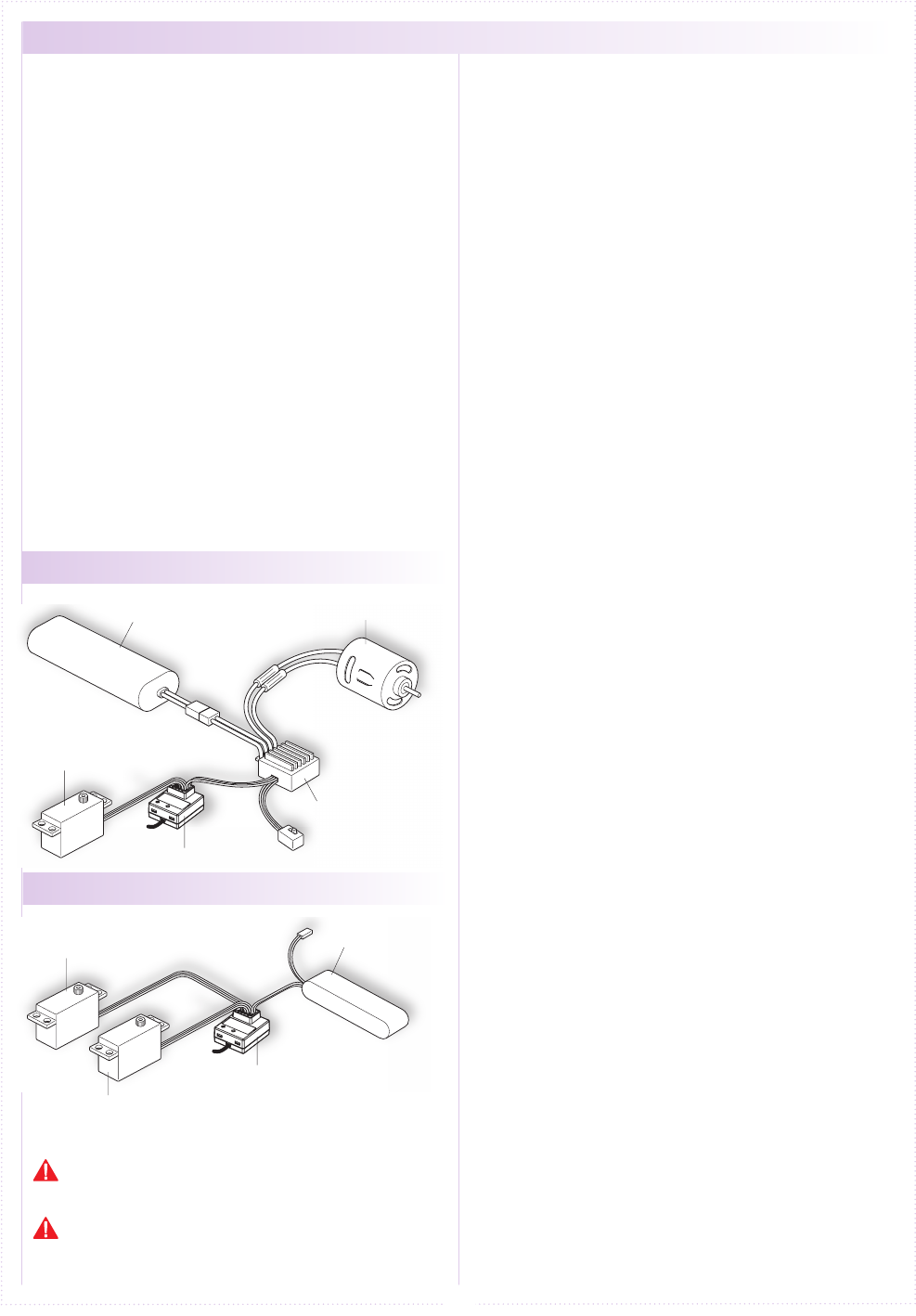
● Receiver Installation
1.
2.
3.
4.
5.
Install the receiver, servo, and ESC (in the case
of an electric car) onto your machine and connect
them. Install the receiver while taking noise into
consideration (p.11).
Install batteries into the transmitter's battery box
(p.9).
In the case of an electric car, install battery pack.
In the case of a glow engine car, install battery for
receiver.
For 2.4GHz systems, conduct pairing of the
transmitter and receiver .
※ In order for the receiver to operate, it must
store the transmitter's unique ID in its memory
in a process called “pairing.” Even if a single
transmitter is used to control multiple receivers,
each receiver must go through the pairing process
with the transmitter before being used for the rst
time.
Adjust steering(p.18)and throttle/braking(p.19).
Set the Fail-Safe Function(p.15).
※ Carefully read the instructions included with the
servo and ESC before installing and using them.
For items which are not included in this product, please
refer to the KO Propo website for a list of compatible
products. (http://www.kopropo.co.jp)
This transmitter is only compatible with digital servos.
Correct operation is not possible when used with analog
servos.
● For an Electric Car
● For a Glow Engine Car
● Battery Pack
(Sold Separately)
● Motor
(Sold Separately)
● ESC (CH2)
(Sold Separately)
● Receiver
● Steering Servo (CH1)
(Sold Separately)
● Steering Servo (CH2)
(Sold Separately)
● Battery for Receiver
(Sold Separately)
● Receiver
● Steering Servo (CH1)
(Sold Separately)
13
BATT
Preparing the Transmitter
① While pushing the ET2 lever up, power on.
② When the ET2 lever is released, the LED turns of
EX-2 LED lights up again (indicating transmitter
is transmitting the pairing signal.)
Case without the Xpansion unit
※ Refer to p.25 pairing Operation in the case of using
the Xpansion unit.
In order for the receiver to operate, it must store the
transmitter's unique ID in its memory in a process
called “pairing.” Even if a single transmitter is used
to control multiple receivers, each receiver must go
through the pairing process with the transmitter before
being used for the rst time.
※ Please adjust the Modulation mode before
pairing.(p.10) A receiver does not work
normally in dierent mode.
During this process, your car may become uncontrollable
if the ESC has not been adjusted. As a precaution, set
your car so that its wheels do not touch the ground.
Pairing procedures may not go smoothly if there
are wireless LAN, microwave ovens, or other users
conducting pairing procedures nearby. In this case, move
some distance away or wait a while before attempting the
pairing procedure again.
If the mode is changed(General or France), please
conduct pairing procedures with the receiver you are
using again.
<France mode pairing >
FRANCE mode pairing is possible when the ET2
lever is released after LED turns o. Please use
this feature if the situation is needed.
1.
2.
3.
ET2
ET2
Power ON
↓
↓
↓
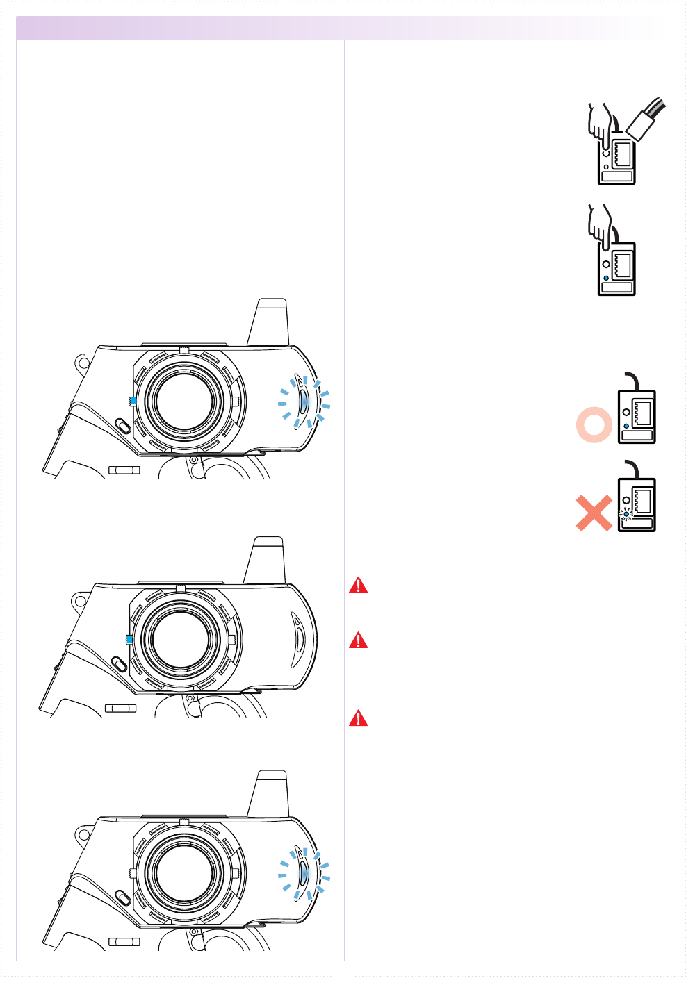
● Pairing (For general receiver)
Preparing the Receiver
① Connect the receiver power
source while pressing the setup
button.
② Check that the receiver's LED
has lit up, then release the setup
button.
③ Check that the receiver's LED
lights up again (indicating pairing
completion)
※ When pairing is complete,
pressing the ENTER key on the
transmitter will return the screen
to the previous [2.4Gband] menu.
※ Switch o the receiver, then
switch it back on again for normal
operations.
※ The preparations below are to be
carried out following the pairing
procedure.
Preparations for Operation
① Switch o the receiver.
② Switch o the EX-2 main power,
then switch on EX-2 again.
③ Switch on the receiver and check
that the receiver LED is lit. If
the LED ashes, the receiver is
not getting the EX-2 signal and
the pairing procedure should be
repeated.
Lit LED
Lit LED
Flashing LED