Kondo Kagaku T39EX2 Radio control transmitter User Manual EX 2 manual En 0530
Kondo Kagaku Co., Ltd. Radio control transmitter EX 2 manual En 0530
Contents
- 1. 06_1_Users_Manual_rev1
- 2. 06_2_Users_Manual_rev1
- 3. 06_3_Users_Manual_rev1
06_2_Users_Manual_rev1
14
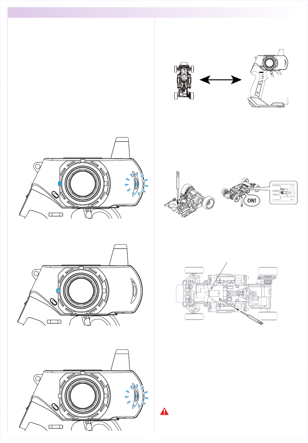
① Bring distance of EX-2 and MiniZ close to about
10cm.
10cm
② Switch on MiniZ while pushing the setup button
of Mini-Z.
Pushing setup botton
Switch on
LED
③ After the Mini-Z's LED has lit up, release the
setup button. Then c heck that the Mini-Z's LED
lights up again (indicating pairing completion)
① Switch o MiniZ.
② Switch o the EX-2 main power, then switch on
EX-2 again.
③ Bring distance of EX-2 and MiniZ close to about
30cm. Switch on the Mini-Z and check that the
receiver LED is lit. If the LED ashes, the Mini-Z
is not getting the EX-2 signal and the pairing
procedure should be repeated.
Preparing the Mini-Z
2.
Preparations for Operation
3.
● Pairing (For MHS Mini-Z)
1.
ET2
ET2
↓
↓
↓
Case without the Xpansion unit
※ Refer to p.26 pairing Operation in the case of
using the Xpansion unit.
In order for the Mini-Z to operate, it must store the
transmitter's unique ID in its memory in a process
called “pairing.” Mini-Z must go through the pairing
process with the transmitter before being used for
the rst time.
※ Please adjust the Modulation mode
before pairing.(p.10) A receiver does
not work normally in dierent mode.
If the mode is changed(General or France), please
conduct pairing procedures with the Mini-Z you are
using again.
Preparing the Transmitter
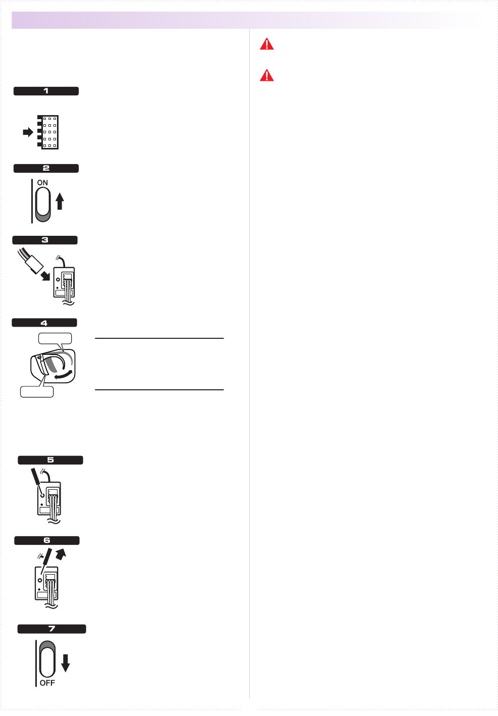
① While pushing the ET2 lever up, power on.
② When the ET2 lever is released, the LED turns of
EX-2 LED lights up again (indicating transmitter
is transmitting the pairing signal.)
<France mode pairing >
FRANCE mode pairing is possible when the ET2
lever is released after LED turns o. Please use
this feature if the situation is needed.
Power ON
↓
B
1
2
3
4
15
Fail-safe is when the receiver loses the radio signal
of the transmitter and the function keeps channel 2
(throttle) in an optional position.
The conguration is usually full brake or neutral.
Press for 3 seconds
LED light goes o
Transmitter OFF
Full brake
Neutral
Transmitter ON
Receiver ON
This function works for only 2nd
channel.
Turn o the transmitter. And the
device that connected into 2nd
Channel will move to the position
that you set up.
While holding the position, press
the setup button on the receiver
for 3 seconds.
Hold the setup button on the
receiver until the LED light goes o
and release the button. Fail-safe
setting is complete.
Recommended positions are the following :
Full Brake
● GP car
● EP car
(forward / Brake)
Neutral
● EP car
(forward / Back)
(forward / Brake / Back)
Turn on the transmitter.
Turn on the receiver and verify
operation.
Hold the throttle to
the position On the
transmitter, hold the
throttle to the position
you would like it to be
set to.
● Fail-Safe Setting
If you change the position of the fail-safe operation,
please set again. We recommend to set it again even
if you modify the car engine brake linkage.
Please be sure to set the fail-safe.
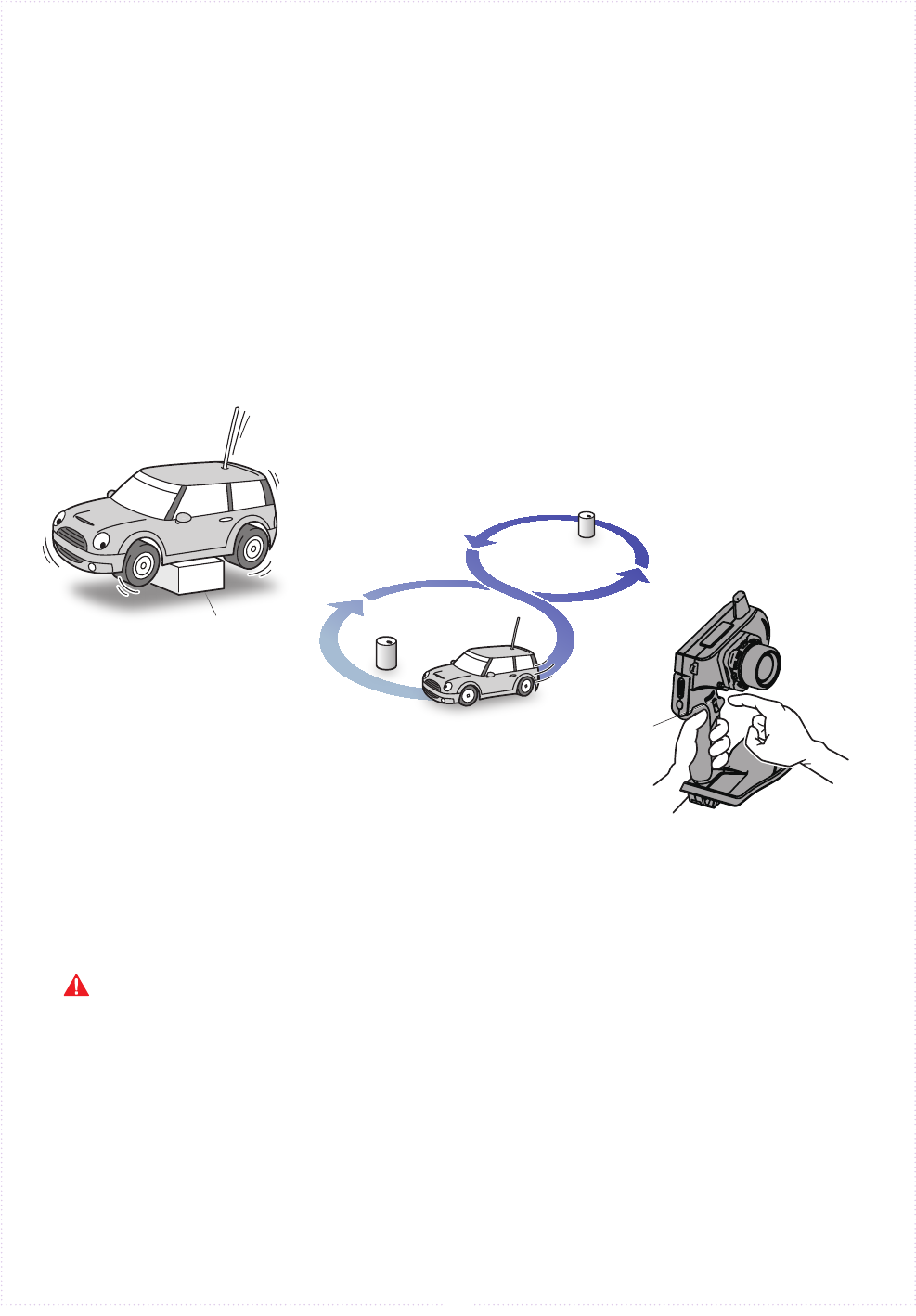
Stand
Figure 8 Pattern
Trim
16
■ Procedures Prior to Operation
1.Switching On
After ensuring that it is safe to do so, switch on the transmitter followed
by the receiver or Mini-Z.
2.Model Conrmation
Conrm the model which will be used.
3.Checking Movements
With the model's wheels lifted o the ground, operate transmitter to check
for proper movement. While driving, use steering and throttle trims to make
ne adjustments. Drive in a gure 8 pattern to check steering balance.
4.Switching O
After a driving session, switch o the receiver (or Mini-Z), followed by the
transmitter. Remove the battery pack from the model.
After switching o, wait at least 5 seconds before switching on again to ensure proper operation.
17
The sub trim is a convenient feature but it could also complicate the setting process if used incorrectly. Use the sub
trim in the correct manner while also referring to the sub trim operation instructions on p.44 and p.49.
● Trim and Sub Trim Operation
Only at the time of expansion setting,
t he sub trim is accessed via the
steering menu, but the steering trim
can be assigned to one of the ET keys
in SETUP.
P
《Purpose of the Sub Trim》
When a servo is to be mounted onto a model, it is usually
connected to the receiver temporarily to enable the transmitter
to check its neutral position before it is installed. However, upon
running the model it is often the case that it does not run in a
straight line and the steering servo's neutral position has to be
readjusted. This adjustment function is known as the “trim,” but
trim adjustment is not only done at the beginning, but it also must
be done during model operation to account for factors such as tire
wear and chassis warp. However, using the normal trim to make
these intermediary adjustments could cause other problems. In
the case of the steering trim, it could lead to dierent turning radii
for the left and right wheels. For throttle trims on glow engine
cars, the point of maximum braking, the full open position of the
carburetor, etc. would be shifted. For this reason, the normal trims
are designated as “center trims” that only adjust the neutral
position, while a new function called sub trim is used in conjunction
to enable the most optimal settings.
《Purpose of the Trim》
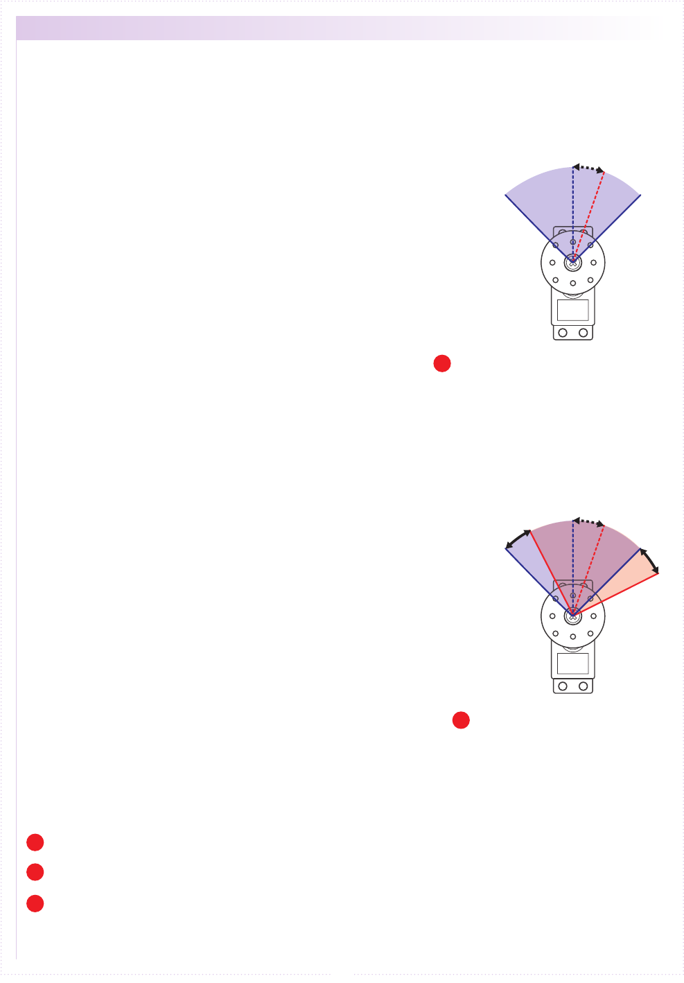
The eect of the sub trim is illustrated in the image on the right.
Adjusting the sub trim also moves the left/right angle range.
In contrast, the center trim moves the neutral position without
changing the angle range position. However, trying to compensate
the neutral position while making large sub trim adjustments may
throw o the model's left/right balance.
《Actual Setting Sequence》
① When installing R/C equipment, the servo's neutral position is
set first, then final adjustments would be made with the sub
trim after installation. However, if the sub trim setting value is
high, adjust the neutral position again.
② Test run to confirm neutral position. Adjustments during this
time should also be made with the sub trim. After neutral
position is xed, adjust steering balance (p.20) so that the left
and right wheels have the same turning radius and use steering
travel (p.19) to adjust overall steering angle.
③ During the course of practice or racing, use the center trim to
correct slight changes to the neutral position. If the setting
value becomes high, correct in conjunction with the sub trim so
that the center trim value is zero.
Use the sub trim to adjust settings prior to driving instead of the center trim.
P
Install R/C equipment when the sub trim setting value becomes low.
P
If the neutral position becomes slightly o during driving, use center trim to correct.
P
Left/Right angle range and neutral
position can be both be adjusted.
● Sub Trim
● Trim (Center Trim)
Left/Right movement
range is xed.
Adjusting neutral position only.
Initially, steering trim and throttle
trim are assigned to ET1 and ET2
respectively.
P
Neutral
Right
MAX.
Left
MAX.
Neutral
Right
MAX.
Left
MAX.
→
ET1
Neutral
Right
MAX.
Left
MAX.
→
ET1
Neutral
Right
MAX.
Left
MAX.
ET1
ET1
18
※ Other than the operation explanation of the
steering wheel,the following function explanation is in
the case of not using the Xpansion unit. Refer to p.43
operation in the case of using the Xpansion unit.
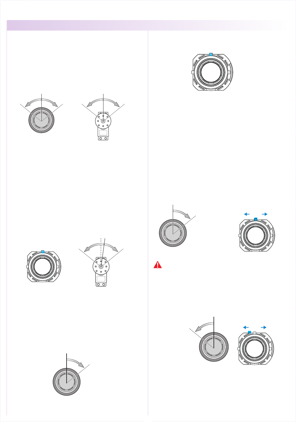
Turn steering in right and left, the servo (steering)
connected to 1CH of the receiver works.
Adjust the left/right steering angles independently.
This enables the turning radii to match up during
cornering.
● Travel R
① Hold steering wheel to all the right
② Push ET1 lever by 1 click, adjust the range of
Steering angle.
● Travel L
① Hold steering wheel to all the Left
② Push ET1 lever by 1 click, adjust the range of
Steering angle.
Changing the output directional movement of the
servo when it is moving in the opposite direction.
(when a steering moves to the left while turning
the steering wheel to the right.)
Adjusts the neutral/center position of the steering
angle range. The function to make a ne adjustment
so that a car goes straight, operate the ET1 lever in
the right and left directions.
● A buzzer sound with a single beep sound when
operated to the right and left.
● A buzzer sound "Piro" is made when the center trim
is adjusted.
● When exceeding the setting range a "Pi-" sound
can be heard. Please look over your installation and
linkage of the servo horn.
< ex. Right >
■ Steering wheel
■ Steering travel
■ Steering reverse
■ Steering trim
● STEERING
① Hold the steering wheel all the way to the right .
③ A single buzzer sounds and the steering
directional movement is reversed.
※ Return reverse setting, perform operation to ①
~③ again.
② Press and hold the ET1 lever to right, wait
about 1 second.
Hold steering wheel
to all the right
Hold steering wheel
to all the right
Do not hold the ET1 lever, or the steering reverse will
be set.
Hold steering wheel
to all the left
■ operating procedure
Neutral
Neutral
Forward Back
(Brake)
ET2
ET2
ET2
Hold throttle trigger
full brake.
Hold throttle trigger
full brake.
ET2
19
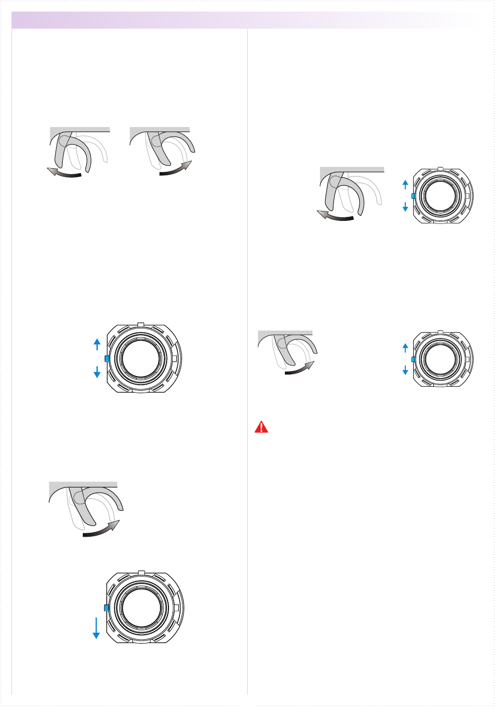
Operating trigger, the servo (ESC) connected to
2CH of the receiver works forward and reverse
function.
Modify the maximum amount of throttle brake
movement and forward acceleration movement.
● Travel F(Forward)
① Hold throttle trigger full throttle.
② Push ET2 lever by 1 click, adjust the range of
throttle movment angle. Quantity of the movement
increases and decreases when operating the ET2
lever up or down respectively.
● Travel B(Brake)
① Hold throttle trigger full brake.
② Push ET2 lever by 1 click, adjust the range of
throttle movment angle. Quantity of the movement
increases and decreases when operating the ET2
lever up or down respectively.
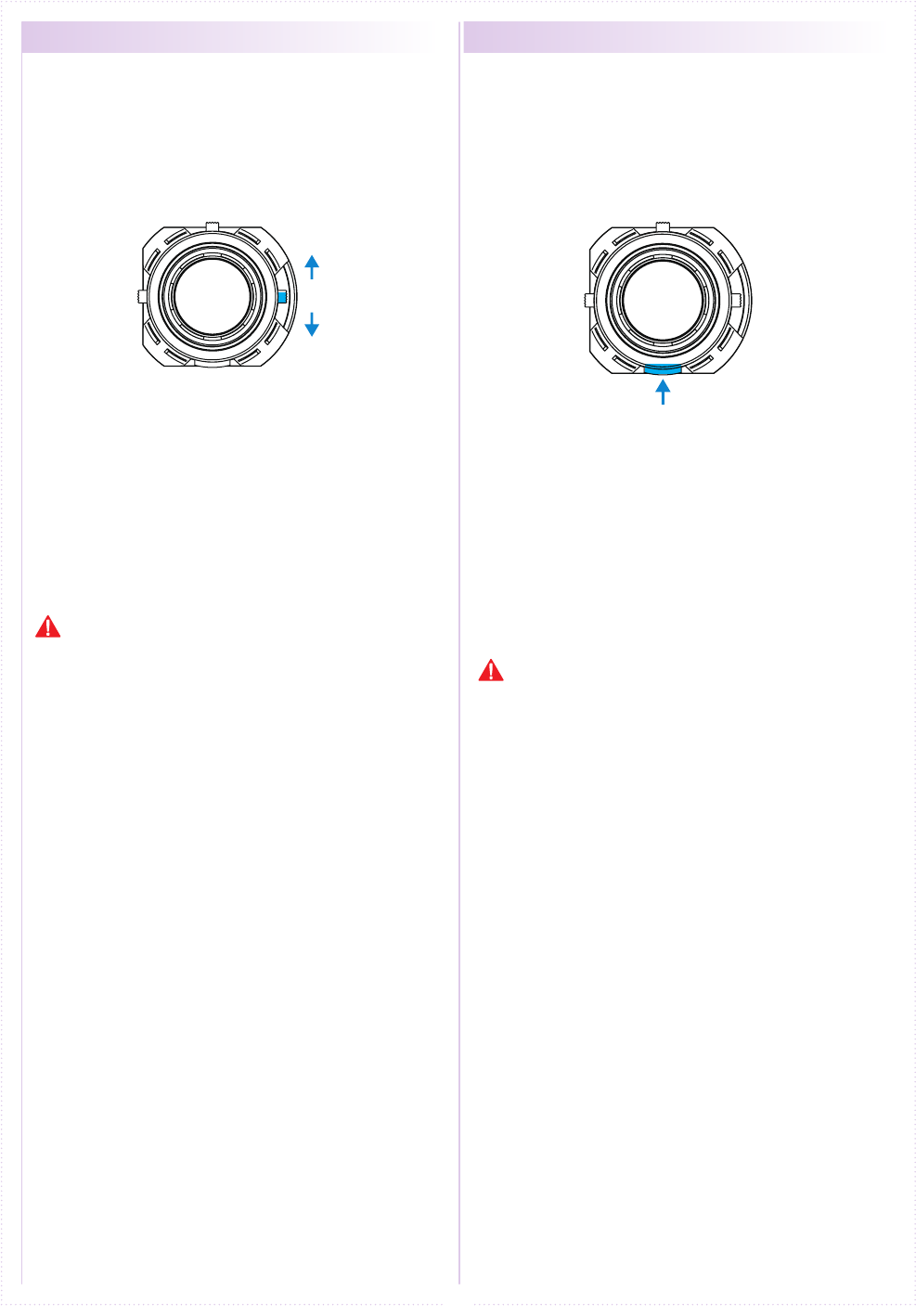
Adjusts the neutral/center position of the throttle
stroke range.The function to make a ne adjustment,
operate ET2 lever in up and down.
● A buzzer sound with a single beep sound when
operated up or down.
● A buzzer sound "Piro" is made when the center
trim is adjusted.
● When exceeding the setting range a "Pi-" sound
can be heard. Please look over your installation and
linkage of the servo horn.
Changing the output directional movement of the
servo when it is moving in the opposite direction.
(when the brake is moving the forward throttle.)
① Hold throttle trigger full brake.
③ A single buzzer sounds and the throttle directional
movement is reversed.
※ Return reverse setting, perform operation to ①~③
again.
② Press and hold the ET2 lever down, wait about
1 second.
Forward
Increase
Increase
Decrease
Decrease
Back
■ Throttle trigger
■ Throttle travel
■ Throttle trim
■ Throttle reverse
● THROTTLE
Hold full throttle
Do not hold the ET2 lever, or the steering reverse will
be set.
※ Other than the operation explanation of the trigger
movement, the following function explanation in case
of not using the Xpansion unit. Refer to p.48 operation
in the case of using the Xpansion unit.
ET3
BT1
20
Operating the ET3 lever, controls the 3ch
servo.
※ The funtion explaination is in the case when not
using the Xpansion unit. Refer to p.33 operation
in the case of assembled Xpansion unit.
When the button of BT1 is operated, it is
possible to operate the signal of 4CH.
※ The funtion explaination is in the case when not
using the Xpansion unit. Refer to p.33 operation
in the case of assembled Xpansion unit.
① using KR-241FH receiver, a servo connected
to 3CH can operate 5WAY .
※ Cannot change setting value.
※ The set point xed –100, -50, 0, 50, 100.
② Use it for steering gyro gain (eect) control as
MiniZ MR-03VE PRO for MHS.
① using KR-241FH receiver, a servo connected
to 4CH can operate 2WAY .
※ Cannot change setting value.
※ The set point xed 0, 100.
② Use it for steering gyro gain (eect) control as
MiniZ MR-03VE PRO for MHS.
Example
Example
● 3CH operation ● 4CH operation
It is possible to do the gyro gain conguration of KR-
212FHG, but because entry value is large, normal
operation is not possible, you cannot use it. It is possible to do the gyro gain conguration of KR-
212FHG, but because entry value is large, normal
operation is not possible, you cannot use it.
ST TURN 50
%
ST RETURN 100
%
ターンスピード
リターンスピード
ST SPEED スピード
ST TURN 100
%
ST RETURN 100
%
ターンスピード
リターンスピード
ST SPEED スピード
ST TURN 50
%
ST RETURN 100
%
ターンスピード
リターンスピード
ST SPEED スピード
ST TURN 100
%
ST RETURN 100
%
ターンスピード
リターンスピード
ST SPEED スピード
21
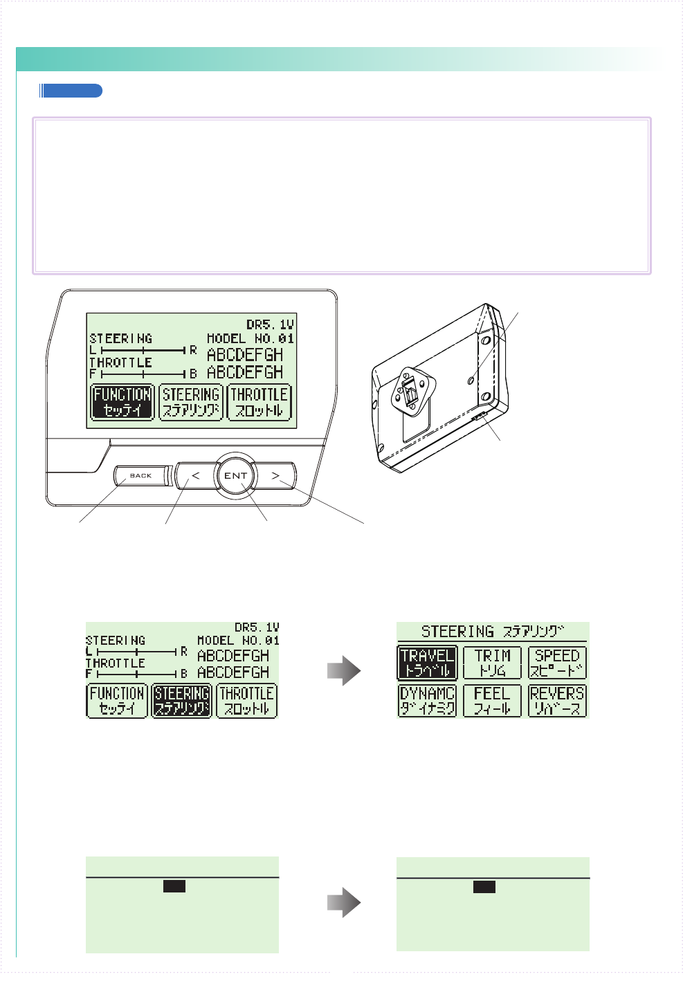
【 Basic Operation 1: Selecting from a Menu 】
This explanation uses [Steering] as an example.
① Use the R(>) key to move the cursor over [Steering].
② Press the ENTER key to change to the Steering Menu screen.
【 Basic Operation 2: Changing a Setting Value 】
This explanation uses [TURN 1] on the Steering Speed screen as an example.
① Use R(>) key to move the cursor over the 100% value next to [ST TURN].
② Press ENTER key to select it for modication.
③ Once selected, the cursor will blink. Now use the L(<)key+R(>)key to change the value.
④ After changing the value, press the ENTER key again to conrm the change.
■
Display and Control Method for attaching the Xpansion unit
● Basic Operations to Change Settings
BACK Key L( < )Key R( > )Key
Command Button
Communication port
Used for rmware upgrading.
Please refer to an update
manual for the details.
Used for rmware upgrading
and ICS communication.
Please refer to an update
manual for the details.
ENT Key
Controlling of the setting adjustments is done via the L(<) key, R(>)key,
ENTER(ENT) key, and BACK key.
Operation
ENT Key: Selecting item to be modied; Conrming a change after a setting change.
L( < )Key: Used to move cursor between menu choices and to change a setting value.
Lowering a value (for L/R cases: raising toward L); Return to a previous menu item.
R( > )Key: Used to move cursor between menu choices and to change a setting value.
Raising value (for L/R cases: raising toward R); Proceed to next menu item.
BACK Key:Returning to previous screen; Canceling change
L(<) key + R(>) key Pressing simultaneously: Resets the value to default setting.
A
B
22
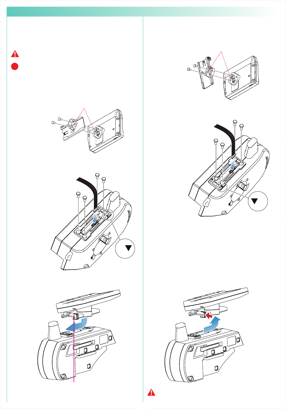
② Attach the monitor bracket to the master
unit. ※[A▼]mark to the steering side
② Attach the monitor bracket to the master
unit. ※ Apply [B ▼] mark to the steering side
① Attach a monitor base parallel to Xpansion
unit. ※ Factory setting.
※ The disassembly method is the same as side
and front positions.
① Attach the monitor base at a right angle to
Xpansion Unit. ※ Dierent Factory setting.
Attention to the marker.
Attention to the marker.
M2.6-6BH
M2.6-6BH
x 2
x 2
x 4
x 4
TP2.6-8BH
Self tapping screws
TP2.6-8BH
Self tapping screws
Connect the wire of the
Xpansion unit to the
master unit.
Connect the wire of the
Xpansion unit to the
master unit.
③ Attach expansion unit to a master unit.
③ Attach the Xpansion unit to the master unit.
※ Attach the monitor base and bracket as
shown in gure A ③ .
1.While pushing the monitor-based apart.
2.Slide the Xpansion like shown in the gure
below and take o.
While matching the edge of the base with
the dent of the bracket, slide it until the
Xpansion unit locks.
A ▼:setting to the front
Xpansion unit can be mounted facing the
front or the side. The factory setting is
mounted to the front.
▼ B:when mounting sideways
How to disassemble the Xpansion unit.
※ Not included with No.10555 EX-2 BASIC set.
When assembling or disassembling the Xpansion unit to
EX-2, please switch o the EX-2.
Be careful to not misuse the M2.6-6BH and TP2.6-
8BH screws.
Xpansioun unit can be mounted in two different
directions using the monitor base and bracket..
P
● Installation of expansion unit
1 2
23
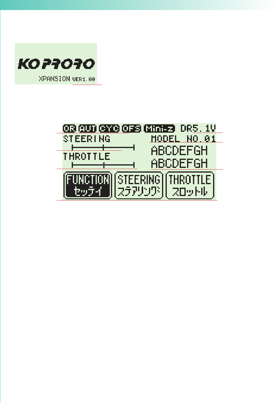
● Startup Screen and Initial Screen
When the transmitter is switched on, the startup screen will display, followed by the initial screen.
※ Pressing the ENTER key during the startup screen will allow you to proceed to the initial screen.
①
①
⑥
⑧
⑦
⑨
②
③
④
① Function Monitor: Functions that are active will be lit up.
② Steering Trim Monitor: Displays the position of the steering trim.
③ Throttle Trim Monitor: Displays the position of the throttle trim.
④ Top menu: Display three kinds of setting items
FUNCTION Modify settings related to functions.
STEERING Modify settings related to the steering.
THROTTLE Modify settings related to the throttle.
⑤ Mini-Z MODE: Functions that are in Mini-Z will be lit up.
⑥ Power Source Type: Displays the type of battery being used.
⑦ Voltage: Displays the current power source voltage.
⑧ Model Number: Displays the currently selected model number.
⑨ Model Name: Displays the name of the currently selected model number.
⑤
① Version Information :
Displays the version of the program that is installed in the Master Unit's CPU.
This product's performance may be upgraded via paid or free upgrades.
Check the KO Propo website for information regarding such upgrades.
( http://www.kopropo.co.jp )
【 Startup Screen 】
【 Initial Screen 】
LP:Li-po
LF:Li-Fe
DR:R03/AAA/UM4 Alkaline Batteries
NI:Ni-MH
OR : Steering and Brake travel Override
AUT : Throttle Auto Start
CYC : Cycle (Throttle Acceleration/Throttle ABS)
OFS : Oset (Drag Brake/Idle Up)
(Notice) If you switch battery types, make sure to also change the [Battery Management] setting.
ST- LEFT
2078
2
ヒダリ
RIGHT
ミギ
NUT
センター
TH- HI
ゼンシン
LOW
ブレーキ
NUT
センター 2075
2072
OK?
YES
2198
2204
2194
VR INFOMATION VRインフォメーション
ST- LEFT
3313
2
ヒダリ
RIGHT
ミギ
NUT
センター
TH- HI
ゼンシン
LOW
ブレーキ
NUT
センター 2075
1463
OK?
YES
2198
3949
487
VR INFOMATION VRインフォメーション
Right MAXLeft MAX
Hold
Full Throttle Hold
Full Brake
24
● VR information setting
Adjust the steering and throttle resistance
information. ※ Please perform the VR information
conguration to calibrate your system.
○ When using EX-2 for the rst time.
○ When changing a steering unit for a dierent
product or when putting it back together.
○ When changing a grip unit for a dierent product
or when putting it back together.
○ When using and confusion has occurred in the
positional information.
1.Select [FUNCTION] on the initial screen and push
the ENTER key.
2.Select [SYSTEM] on the function screen and push
the ENTER key.
3.Select [VR INFO] on the system screen and push
the ENTER key.
4.Move the wheel slowly to the full left and right lock
(numbers will change as the steering is moved) and
release the wheel back to neutral.
5.Move the trigger slowly to the full throttle and full
brake positions (numbers will change as the
throttle is moved) and release the trigger back to
neutral.
6.Then select YES (press ENTER) to adjust and save
the settings.
4,5, Move slowly to full stroke, then release.
3.Example before setting
6, Small window [Yes] comes active.
※ When operating the VR INFORMATION and
pressing the BACK key will cancel the operation.
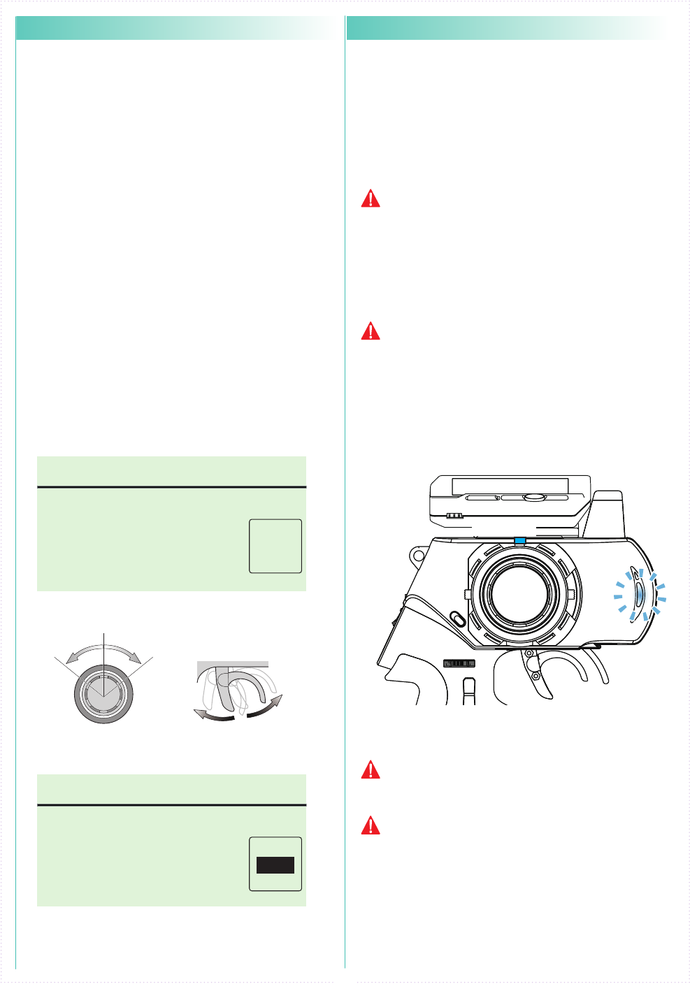
●
How to change the Modulation mode
EX-2 has two Modulation modes.
※ When attaching the Xpansion unit, this operation
is the same.
※ Functions that are in Mini-Z will be lit up at initial
screen.
① Turn o EX-2 switch.
② Push the ET1 lever to the left and power on.
③ Hold ET1 lever until the buzzer sounds and the
LED of EX-2 turns on
(approximately two seconds).
● General RC models FHSS mode:
LED Solid
Operating the general receivers such as KR-211FH/KR-
241FH Only receivers using FHSS will work.
● Mini-Z MHS mode :LED Flashing slowly
Oparating Kyosho Mini-Z MHS mode. (MR-03 VE
PRO)
The receiver of other methods (DSSS/27/40MHz)
do not work.
Only MiniZ using MHS will work. Does not work with
ASF, FHS, general RC cars.
If the pilot LED is blinking fast, this is a warning
that the battery voltage is low. Please change to
new batteries or for a battery pack which has been
charged.
Model selection changes and modulation mode
changes are not linked.
PowerON
↓
↓
↓
ET1
Approximately two
seconds, LED turns on.
《Functions》
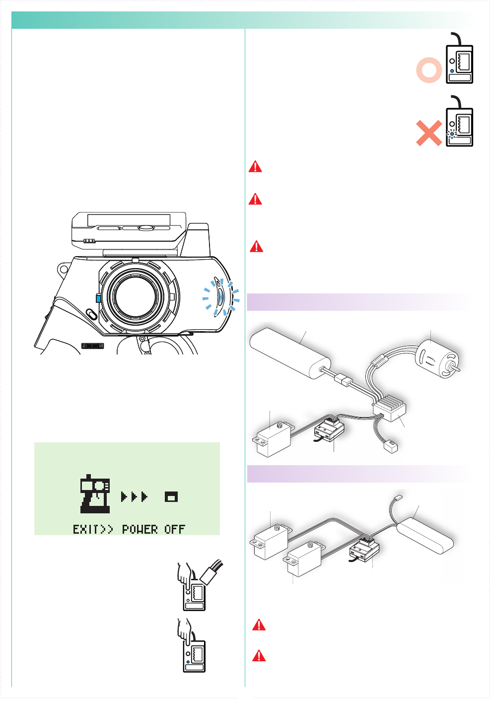
● For an Electric Car
● For a Glow Engine Car
● Battery Pack
(Sold Separately)
● Motor
(Sold Separately)
● ESC (CH2)
(Sold Separately)
● Receiver
● Steering Servo (CH1)
(Sold Separately)
● Steering Servo (CH2)
(Sold Separately)
● Battery for Receiver
(Sold Separately)
● Receiver
● Steering Servo (CH1)
(Sold Separately)
25
● Pairing (For general receiver)
④ Set the Fail-Safe Function(p.15).
Preparing the Transmitter
① While pushing the ET2 lever up, power on.
The pilot LED lights up, release ET2 lever.
Case of using the Xpansion unit
※ Refer to p.13 pairing Operation when not using the
Xpansion unit.
In order for the receiver to operate, it must store the
transmitter's unique ID in its memory in a process
called “pairing.” Even if a single transmitter is used
to control multiple receivers, each receiver must go
through the pairing process with the transmitter
before being used for the rst time.
※ Please adjust the modulation mode before pairing.
(p.24) A receiver does not work normally in a dierent
mode.
1.
ET2
PowerON
↓
↓
↓
<France mode pairing >
FRANCE mode pairing is possible when the ET2 lever is
released after LED turns off. Please use this feature if the
situation is needed.
② Displays the initial screen, then pairing display is
shown. (indicating transmitter is transmitting the
pairing signal.)
2.
Preparing the Receiver
① Connect the receiver power
source while pressing the
setup button.
② Check that the receiver's LED
has lit up, then release the
setup button.
③ Check that the receiver's LED
lights up again (indicating
pairing completion)
BATT
Lit LED
During this process, your car may become uncontrollable
if the ESC has not been adjusted. As a precaution, set
your car so that its wheels do not touch the ground.
Pairing procedures may not go smoothly if there
are wireless LAN, microwave ovens, or other users
conducting pairing procedures nearby. In this case, move
some distance away or wait a while before attempting the
pairing procedure again.
If the mode is changed(General or France), please
conduct pairing procedures with the receiver you are
using again.
3.
Preparations for Operation
① Switch o the receiver.
② Switch o the EX-2 main power,
then switch on EX-2 again.
③ Switch on the receiver and check
that the receiver LED is lit. If
the LED ashes, the receiver is
not getting the EX-2 signal and
the pairing procedure should be
repeated.
Lit LED
Flashing LED
For items which are not included in this product, please
refer to the KO Propo website for a list of compatible
products. (http://www.kopropo.co.jp)
This transmitter is only compatible with digital servos.
Correct operation is not possible when used with analog
servos.
26
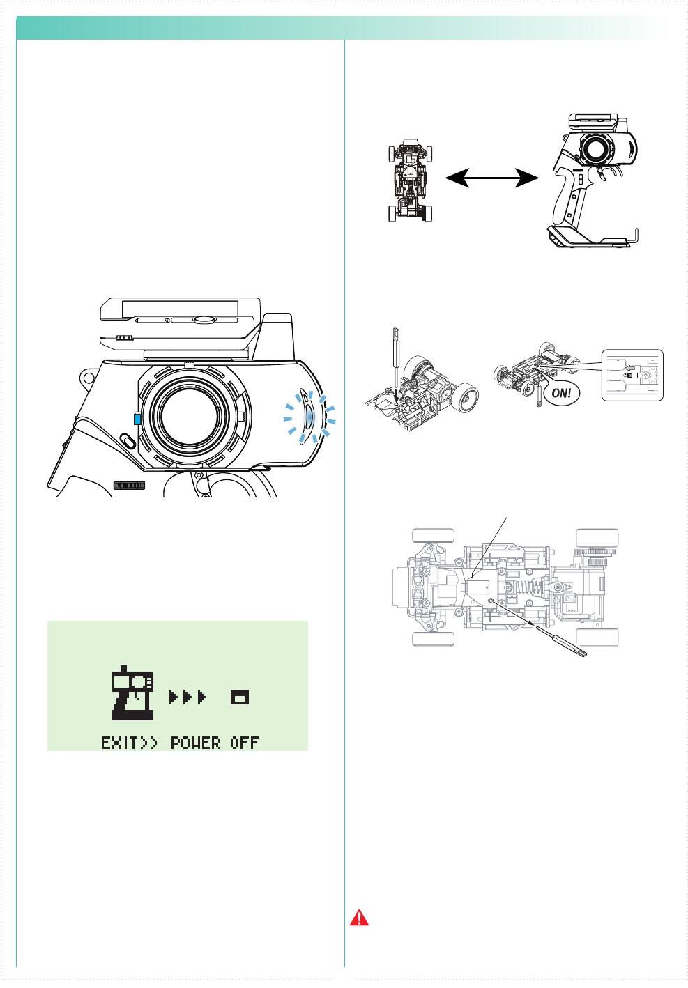
① Bring distance of EX-2 and MiniZ close to about
10cm.
② Switch on MiniZ while pushing the setup button
of Mini-Z.
Pushing setup botton
Switch on
LED
③ After the Mini-Z's LED has lit up, release the
setup button. Then c heck that the Mini-Z's LED
lights up again (indicating pairing completion)
① Switch o MiniZ.
② Switch o the EX-2 main power, then switch on
EX-2 again.
④ Bring distance of EX-2 and MiniZ close to about
30cm. Switch on the Mini-Z and check that the
receiver LED is lit. If the LED ashes, the Mini-Z
is not getting the EX-2 signal and the pairing
procedure should be repeated.
Preparing the Mini-Z
2.
Preparations for Operation
3.
If the mode is changed(General or France), please
conduct pairing procedures with the Mini-Z you are using
again.
10cm
● Pairing (For MiniZ MHS)
Preparing the Transmitter
① While pushing the ET2 lever up, power on.
The pilot LED lights up, release ET2 lever.
Case of using the Xpansion unit
※ Refer to p.13 pairing Operation when not using the
Xpansion unit.
In order for the receiver to operate, it must store the
transmitter's unique ID in its memory in a process
called “pairing.” Even if a single transmitter is used
to control multiple receivers, each receiver must go
through the pairing process with the transmitter
before being used for the rst time.
※ Please adjust the modulation mode before pairing.
(p.24) A receiver does not work normally in a dierent
mode.
1.
ET2
PowerON
↓
↓
↓
<France mode pairing >
FRANCE mode pairing is possible when the ET2 lever is
released after LED turns off. Please use this feature if the
situation is needed.
② Displays the initial screen, then pairing display is
shown. (indicating transmitter is transmitting the
pairing signal.)
27
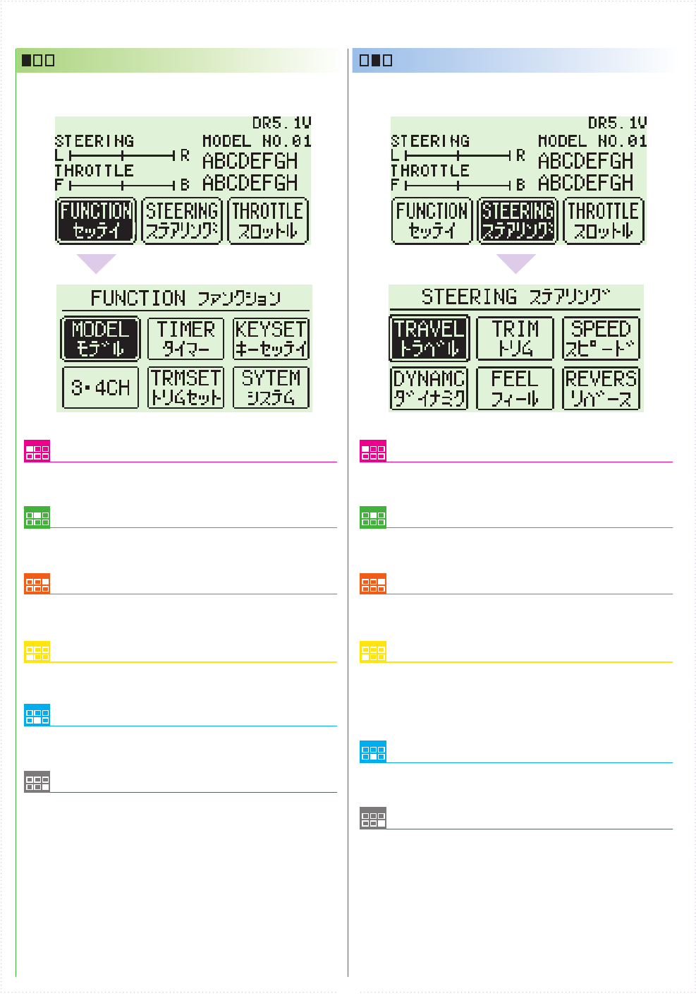
Model Menu (MODEL)
Operations such as selecting or copying a model.
Steering Travel
Modify the overall amount of steering
movement.
3CH/4CH Menu (3/4ch)
Modify settings related to 3CH and 4CH.
Steering Dynamics
Modify the movement speed ratio which
corresponds to steering angle and Modify how
much the steering initially turns from neutral
position.
Trim set Menu(TRIM SET)
Easy adjust function for steering trim and
balance. Steering Feel
Modify the feeling of the steering's movement.
Timer Menu (TIMER)
Operating timer-related functions.
Steering Trim
Modify the neutral position of the steering
angle.
Key set Menu (KEY SET)
Modify system-related functions such as key
assignment.
Steering Turn Speed
odify the speed of the steering's movement.
System Menu (System)
Modify system-related functions such as VR
information or calculator. Steering Reverse
Modify the steering direction.
■ TOP MENU
FUNCTION STEERING
This an index which displays the 6 dierent function
menus.
This an index which displays the 6 dierent function
menus.
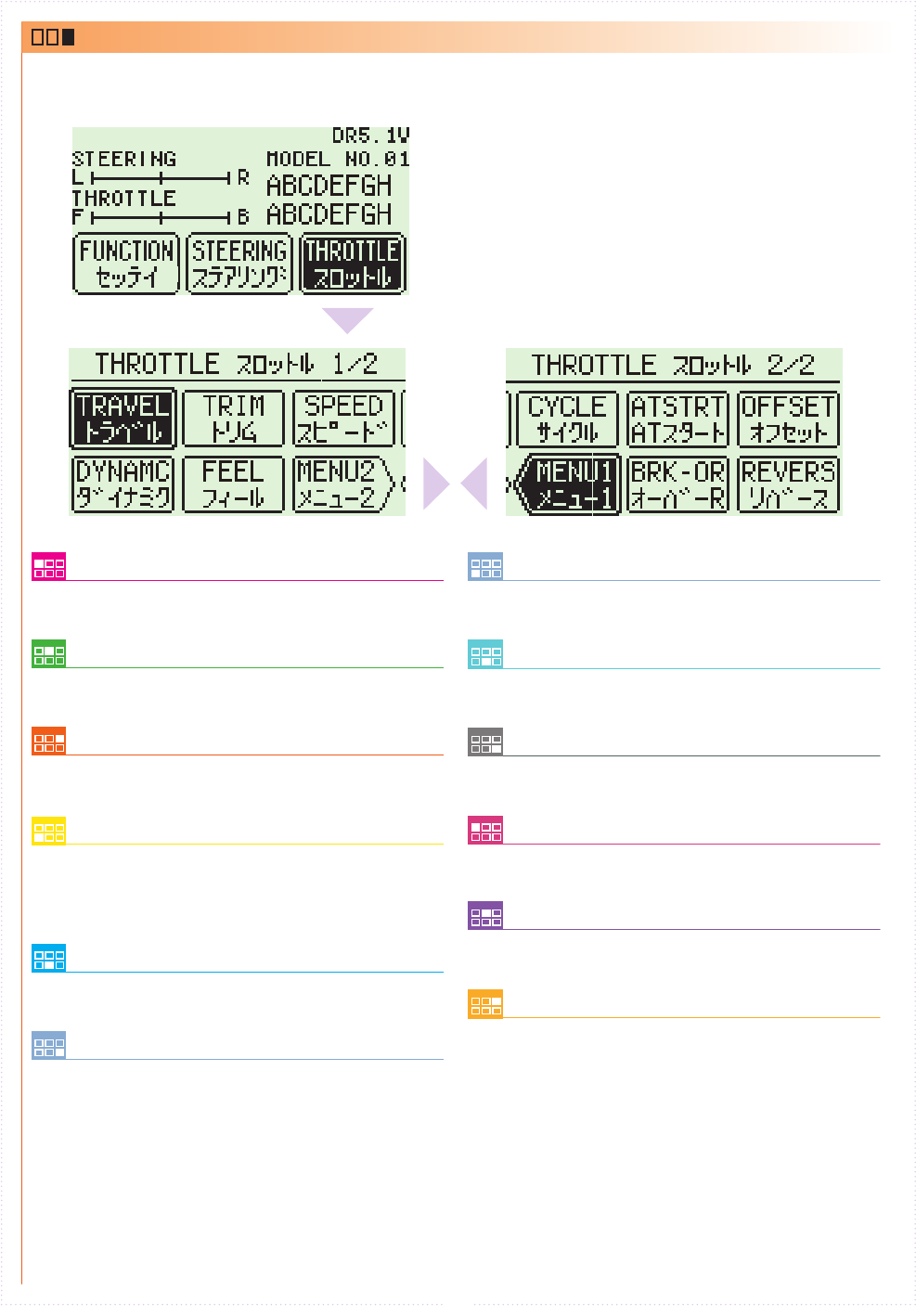
28
Throttle Travel
Modify the maximum throttle movement.
MENU1
Jump menu to throttle menu1.
Throttle Dynamics
Modify the movement speed ratio which
corresponds to throttle angle and Modify how
much the throttle initially moves from the
neutral position.
Idle Up
Modify the neutral position of the throttle
trigger or neutral braking.
Throttle Feel
Modify the feeling of the throttle movement.
Brake Override
Modify the maximum amount of braking and
steering travel assigned to a switch.
Throttle Trim
Modify the neutral position of the throttle.
Throttle Cycle
Modify the amount of brake pumping and
acceleration.
Throttle Turn Speed
Modify the speed of the throttle's movement.
Throttle Auto-Start
Set the amount of automatic startup for the
throttle.
MENU2
Jump menu to throttle menu2.
Throttle Reverse
Modify the throttle direction.
THROTTLE
This an index which displays the 10 dierent function
menus.(Separeted 2 pages.)