Kondo Kagaku T39EX2 Radio control transmitter User Manual EX 2 manual En 0530
Kondo Kagaku Co., Ltd. Radio control transmitter EX 2 manual En 0530
Contents
- 1. 06_1_Users_Manual_rev1
- 2. 06_2_Users_Manual_rev1
- 3. 06_3_Users_Manual_rev1
06_2_Users_Manual_rev1
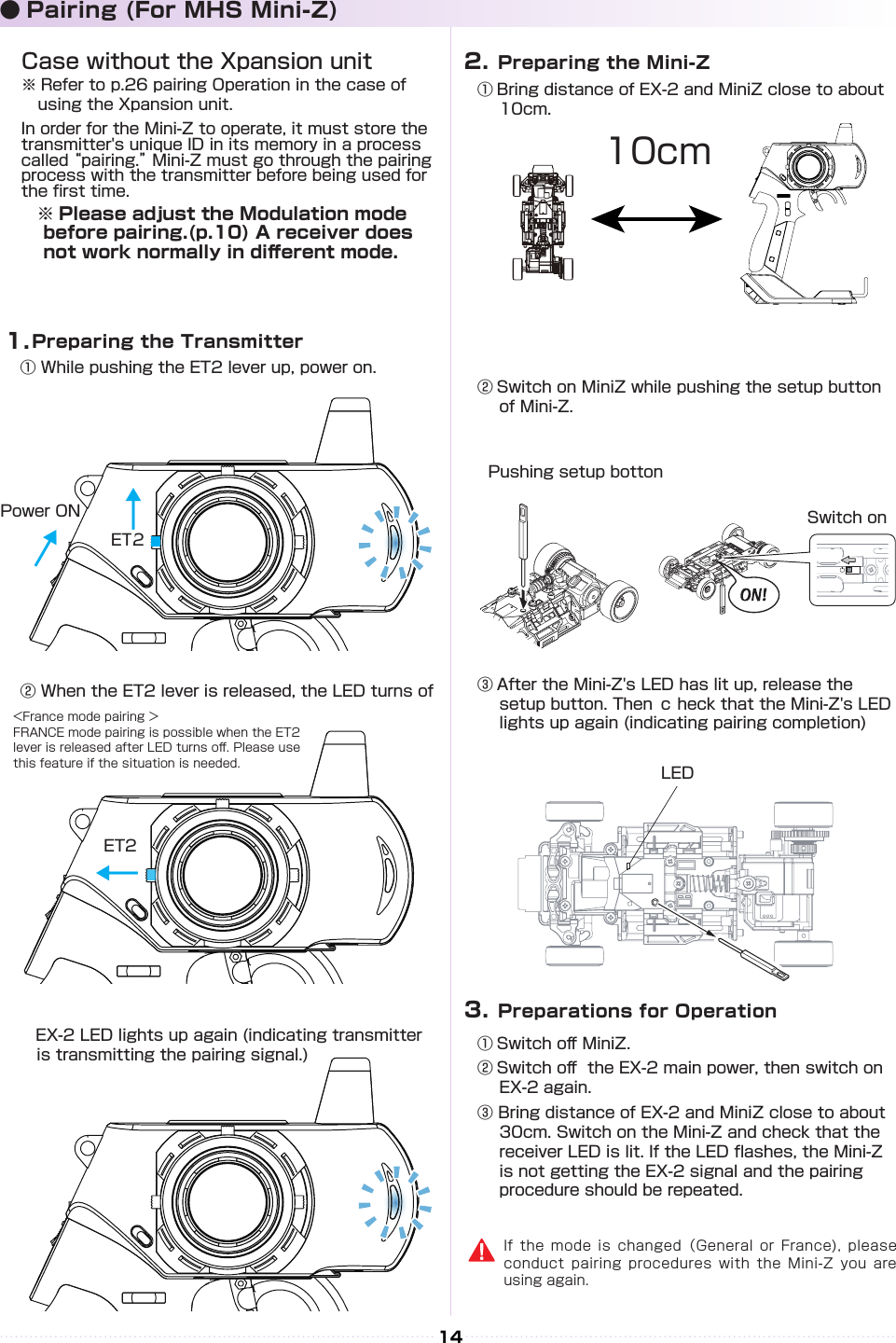
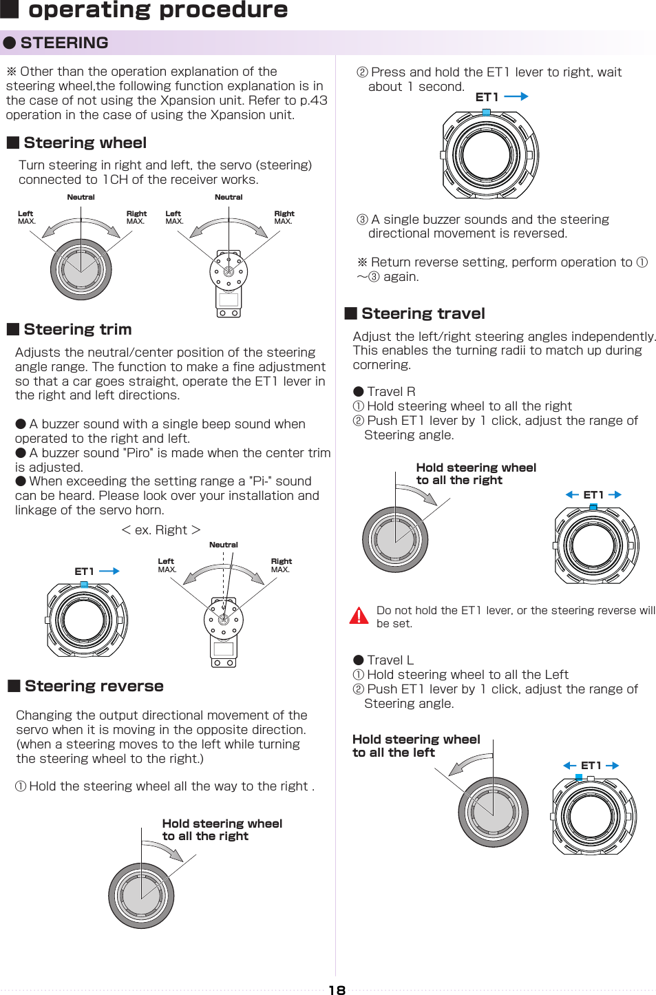
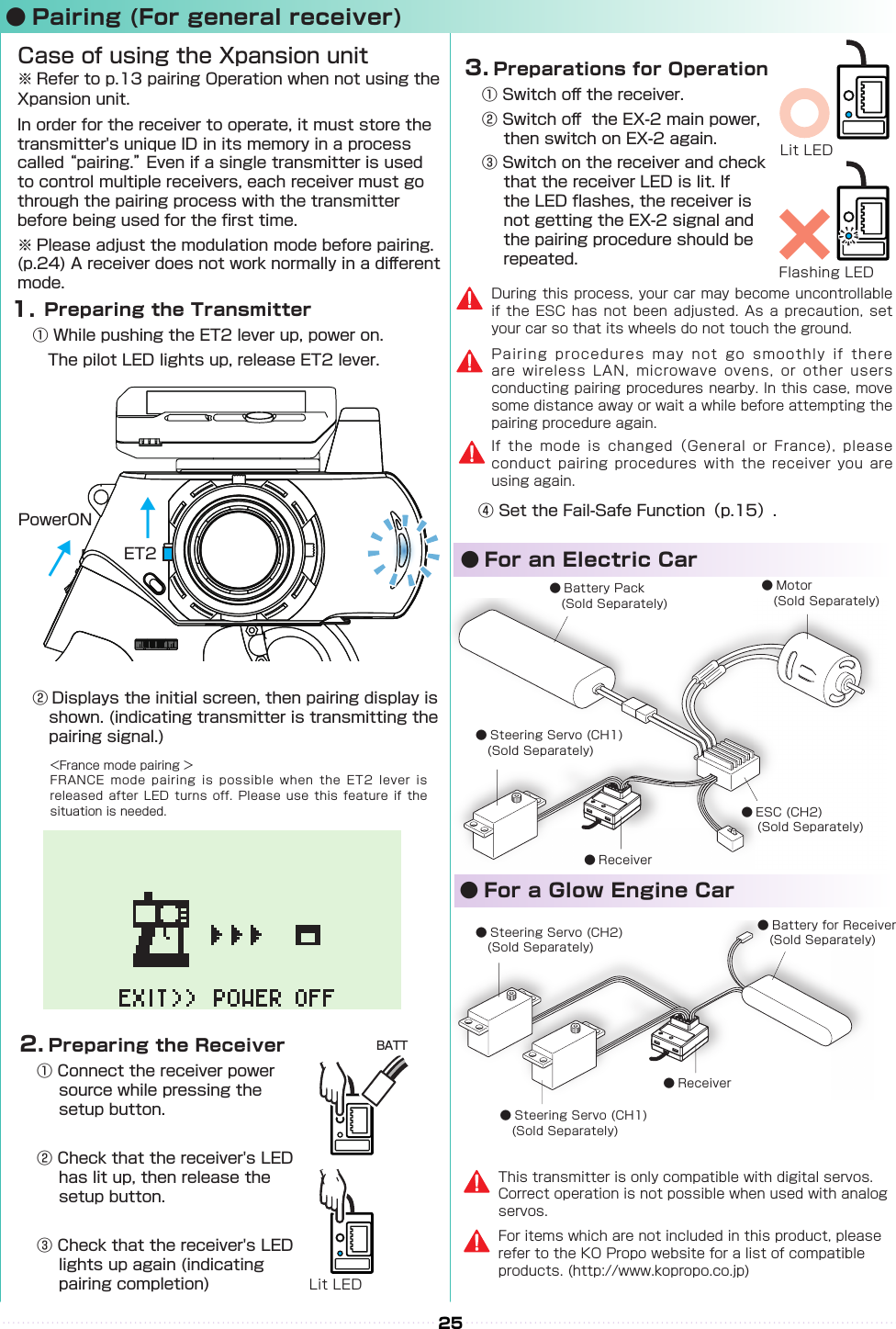
![ST TURN 50%ST RETURN 100%ターンスピードリターンスピードST SPEED スピードST TURN 100%ST RETURN 100%ターンスピードリターンスピードST SPEED スピードST TURN 50%ST RETURN 100%ターンスピードリターンスピードST SPEED スピードST TURN 100%ST RETURN 100%ターンスピードリターンスピードST SPEED スピード21【 Basic Operation 1: Selecting from a Menu 】 This explanation uses [Steering] as an example. ① Use the R(>) key to move the cursor over [Steering]. ② Press the ENTER key to change to the Steering Menu screen.【 Basic Operation 2: Changing a Setting Value 】 This explanation uses [TURN 1] on the Steering Speed screen as an example. ① Use R(>) key to move the cursor over the 100% value next to [ST TURN]. ② Press ENTER key to select it for modication. ③ Once selected, the cursor will blink. Now use the L(<)key+R(>)key to change the value. ④ After changing the value, press the ENTER key again to conrm the change.■ Display and Control Method for attaching the Xpansion unit● Basic Operations to Change SettingsBACK Key L( < )Key R( > )KeyCommand ButtonCommunication portUsed for rmware upgrading.Please refer to an update manual for the details.Used for rmware upgrading and ICS communication. Please refer to an update manual for the details.ENT KeyControlling of the setting adjustments is done via the L(<) key, R(>)key, ENTER(ENT) key, and BACK key.OperationENT Key: Selecting item to be modied; Conrming a change after a setting change. L( < )Key: Used to move cursor between menu choices and to change a setting value. Lowering a value (for L/R cases: raising toward L); Return to a previous menu item.R( > )Key: Used to move cursor between menu choices and to change a setting value. Raising value (for L/R cases: raising toward R); Proceed to next menu item.BACK Key:Returning to previous screen; Canceling changeL(<) key + R(>) key Pressing simultaneously: Resets the value to default setting.](https://usermanual.wiki/Kondo-Kagaku/T39EX2.06-2-Users-Manual-rev1/User-Guide-2644054-Page-8.png)
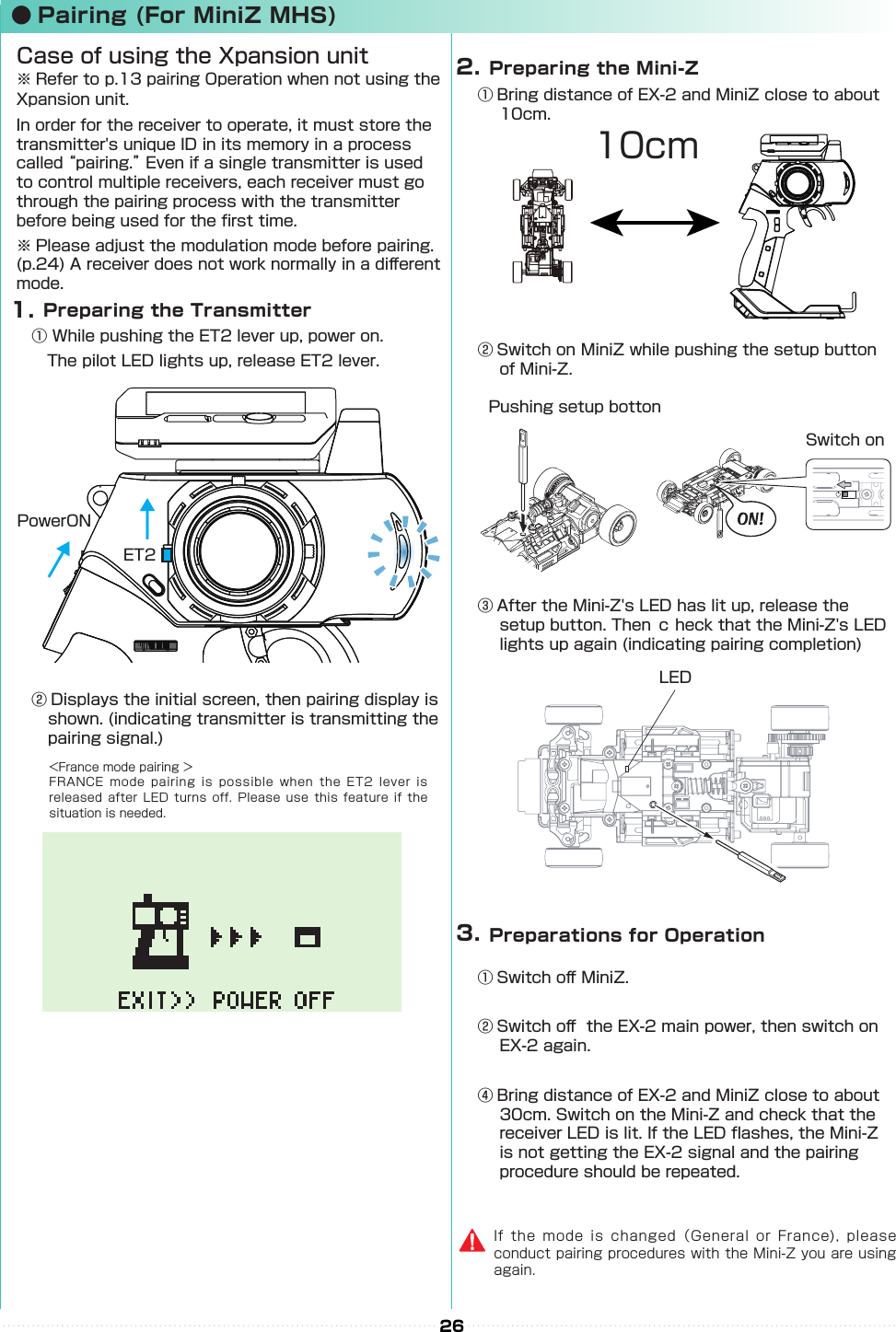
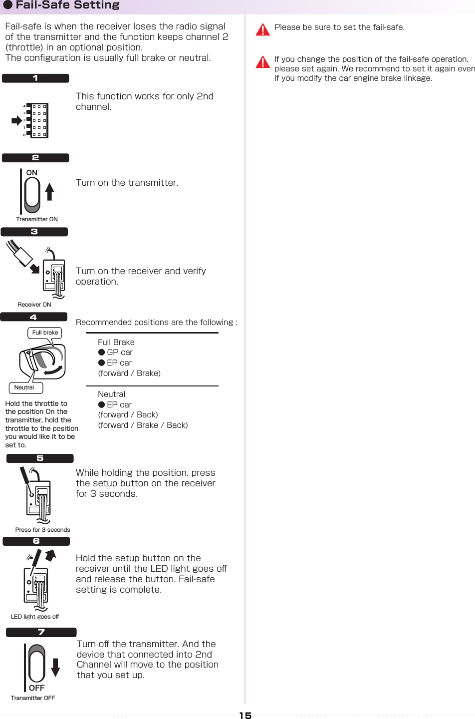
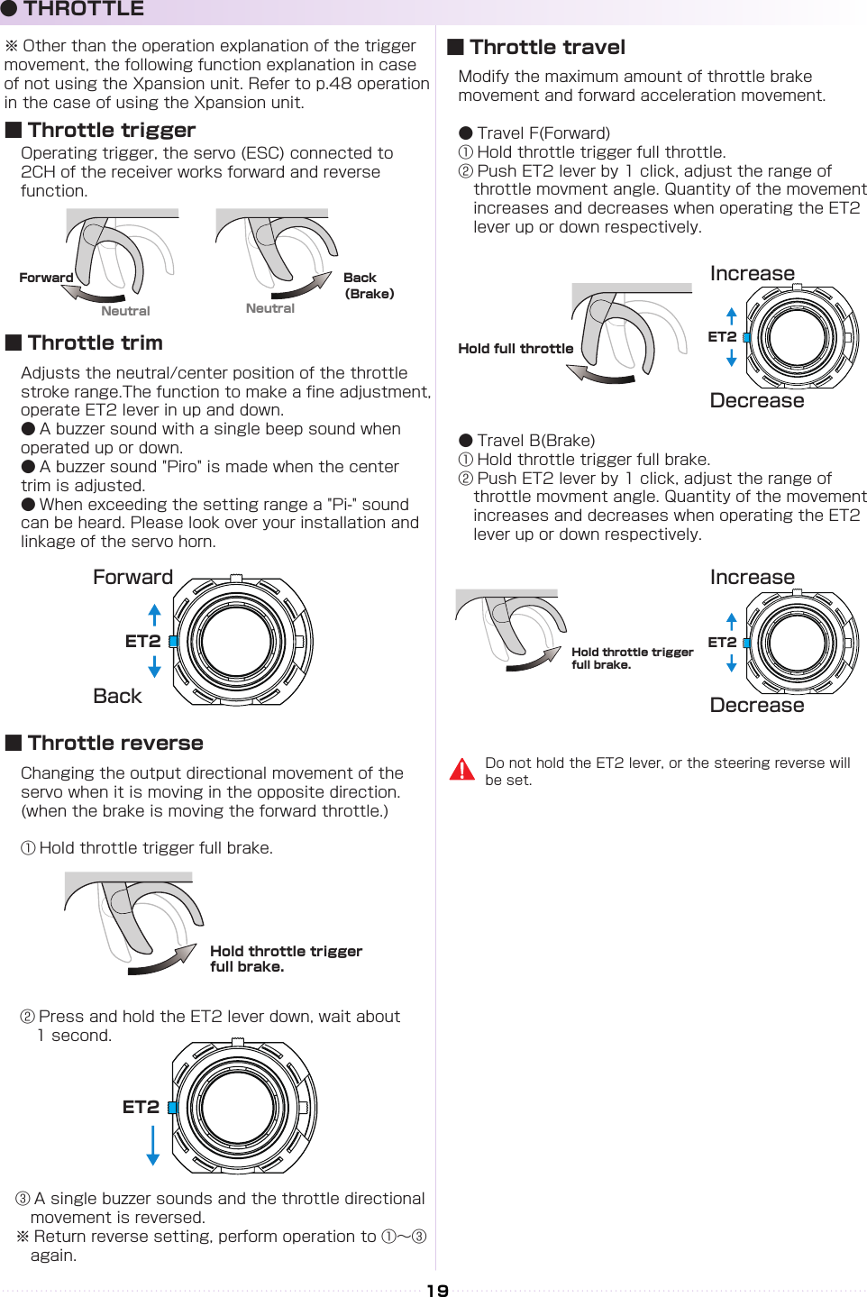
![AB22② Attach the monitor bracket to the master unit. ※[A▼]mark to the steering side② Attach the monitor bracket to the master unit. ※ Apply [B ▼] mark to the steering side① Attach a monitor base parallel to Xpansion unit. ※ Factory setting.※ The disassembly method is the same as side and front positions.① Attach the monitor base at a right angle to Xpansion Unit. ※ Dierent Factory setting.Attention to the marker.Attention to the marker.M2.6-6BHM2.6-6BHx 2x 2x 4x 4TP2.6-8BHSelf tapping screwsTP2.6-8BHSelf tapping screwsConnect the wire of the Xpansion unit to the master unit.Connect the wire of the Xpansion unit to the master unit.③ Attach expansion unit to a master unit.③ Attach the Xpansion unit to the master unit. ※ Attach the monitor base and bracket as shown in gure A ③ .1.While pushing the monitor-based apart.2.Slide the Xpansion like shown in the gure below and take o.While matching the edge of the base with the dent of the bracket, slide it until the Xpansion unit locks.A ▼:setting to the frontXpansion unit can be mounted facing the front or the side. The factory setting is mounted to the front.▼ B:when mounting sidewaysHow to disassemble the Xpansion unit.※ Not included with No.10555 EX-2 BASIC set.When assembling or disassembling the Xpansion unit to EX-2, please switch o the EX-2.Be careful to not misuse the M2.6-6BH and TP2.6-8BH screws.Xpansioun unit can be mounted in two different directions using the monitor base and bracket..P● Installation of expansion unit1 2](https://usermanual.wiki/Kondo-Kagaku/T39EX2.06-2-Users-Manual-rev1/User-Guide-2644054-Page-9.png)
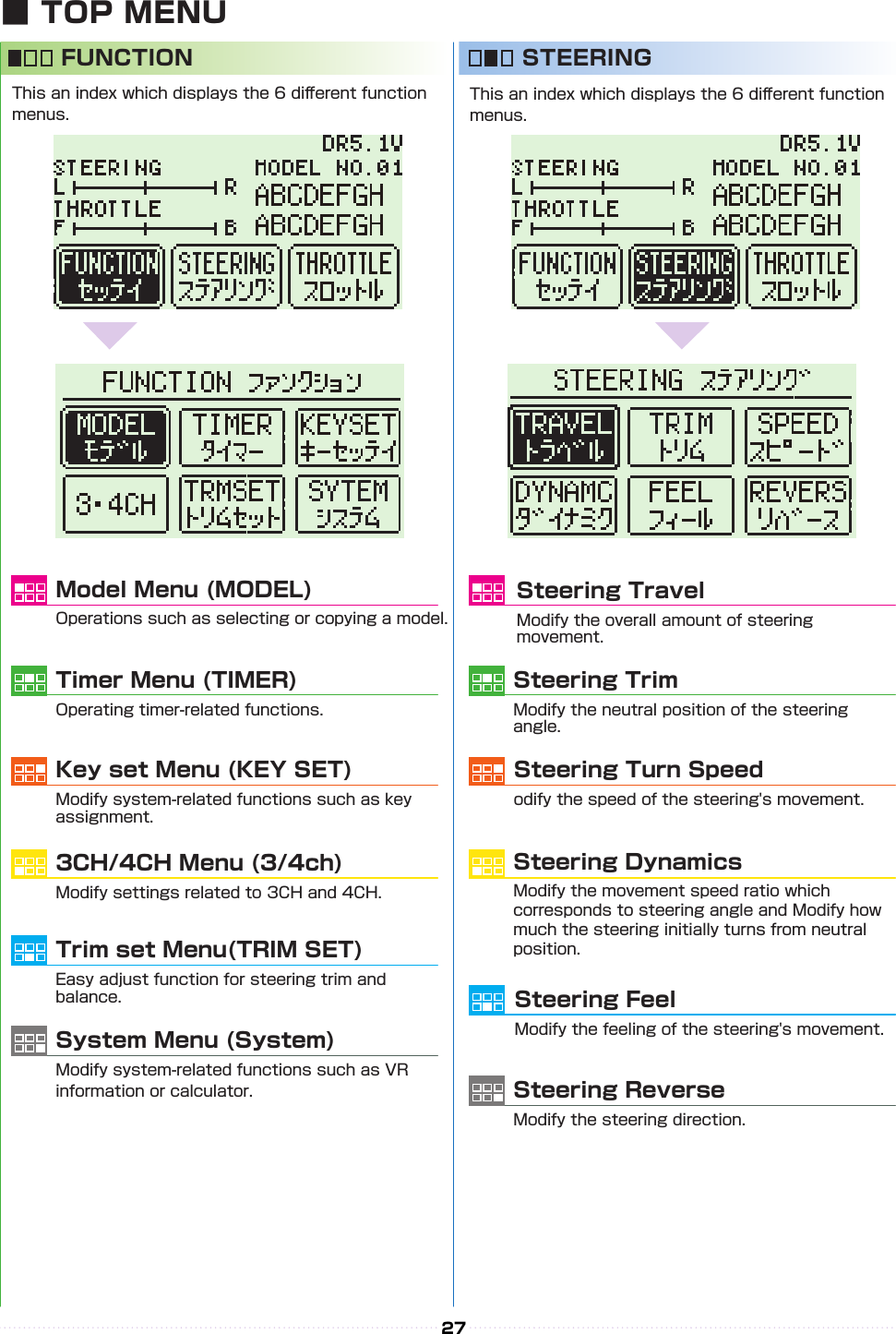
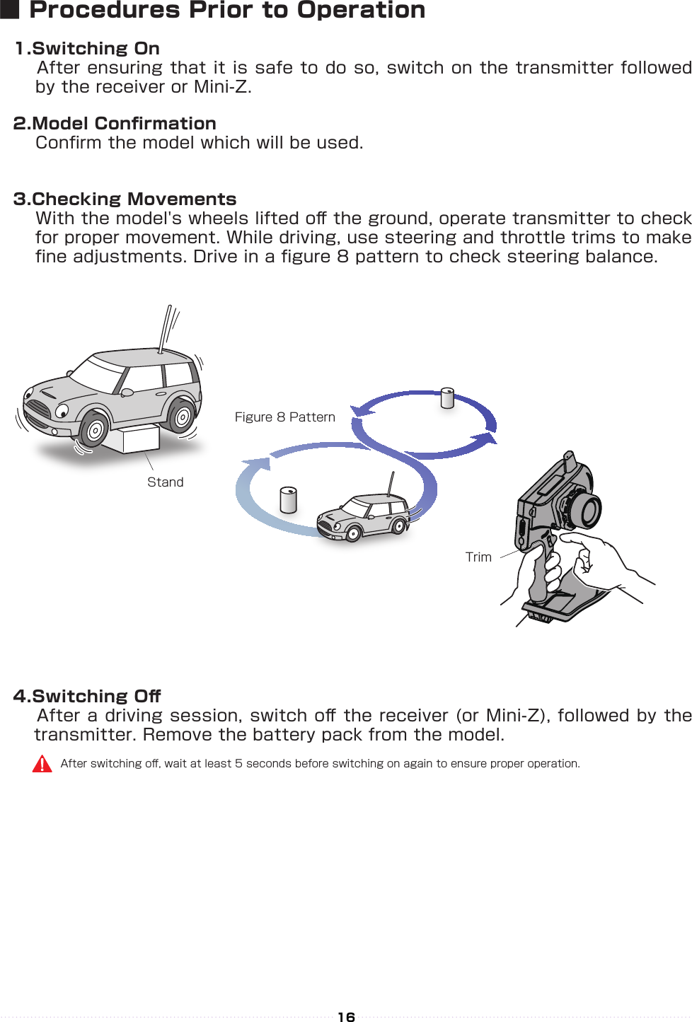
![23● Startup Screen and Initial ScreenWhen the transmitter is switched on, the startup screen will display, followed by the initial screen.※ Pressing the ENTER key during the startup screen will allow you to proceed to the initial screen.①①⑥⑧⑦⑨②③④① Function Monitor: Functions that are active will be lit up.② Steering Trim Monitor: Displays the position of the steering trim.③ Throttle Trim Monitor: Displays the position of the throttle trim.④ Top menu: Display three kinds of setting items FUNCTION Modify settings related to functions. STEERING Modify settings related to the steering. THROTTLE Modify settings related to the throttle.⑤ Mini-Z MODE: Functions that are in Mini-Z will be lit up.⑥ Power Source Type: Displays the type of battery being used.⑦ Voltage: Displays the current power source voltage.⑧ Model Number: Displays the currently selected model number.⑨ Model Name: Displays the name of the currently selected model number.⑤① Version Information :Displays the version of the program that is installed in the Master Unit's CPU.This product's performance may be upgraded via paid or free upgrades. Check the KO Propo website for information regarding such upgrades. ( http://www.kopropo.co.jp ) 【 Startup Screen 】【 Initial Screen 】LP:Li-poLF:Li-FeDR:R03/AAA/UM4 Alkaline BatteriesNI:Ni-MHOR : Steering and Brake travel OverrideAUT : Throttle Auto StartCYC : Cycle (Throttle Acceleration/Throttle ABS)OFS : Oset (Drag Brake/Idle Up)(Notice) If you switch battery types, make sure to also change the [Battery Management] setting.](https://usermanual.wiki/Kondo-Kagaku/T39EX2.06-2-Users-Manual-rev1/User-Guide-2644054-Page-10.png)
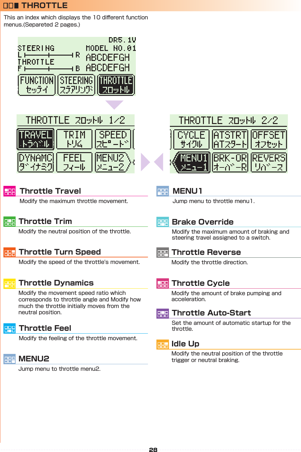
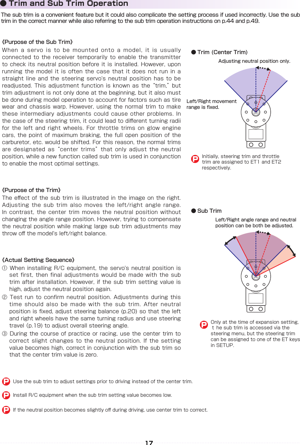
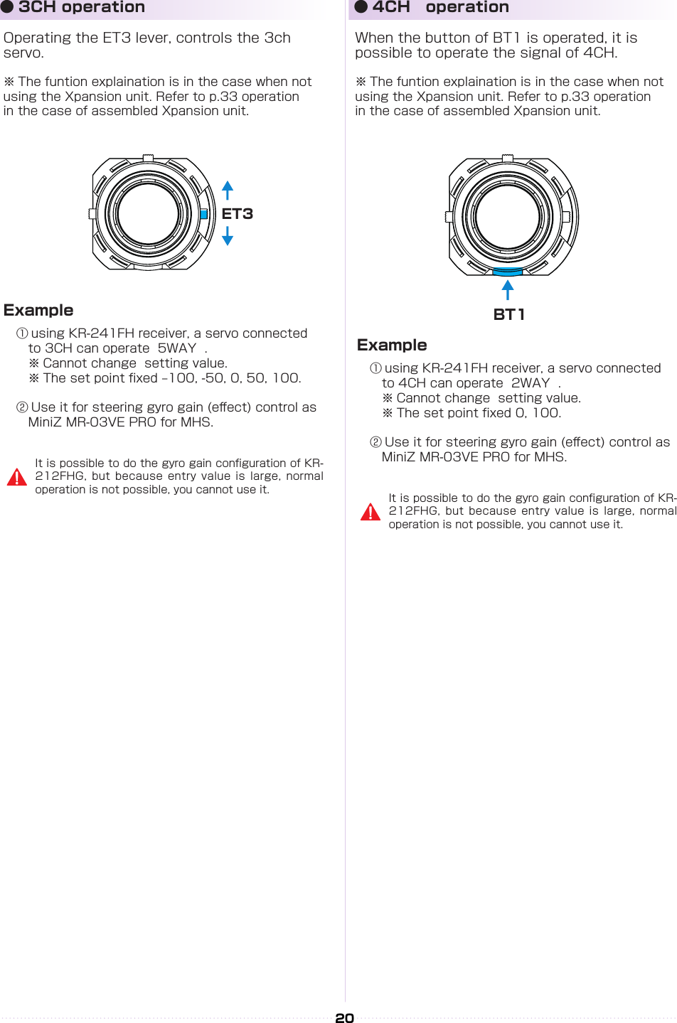
![ST- LEFT20782ヒダリRIGHTミギNUTセンターTH- HIゼンシンLOWブレーキNUTセンター 20752072OK?YES219822042194VR INFOMATION VRインフォメーションST- LEFT33132ヒダリRIGHTミギNUTセンターTH- HIゼンシンLOWブレーキNUTセンター 20751463OK?YES21983949487VR INFOMATION VRインフォメーションRight MAXLeft MAXHoldFull Throttle HoldFull Brake24● VR information settingAdjust the steering and throttle resistance information. ※ Please perform the VR information conguration to calibrate your system.○ When using EX-2 for the rst time.○ When changing a steering unit for a dierent product or when putting it back together.○ When changing a grip unit for a dierent product or when putting it back together.○ When using and confusion has occurred in the positional information.1.Select [FUNCTION] on the initial screen and push the ENTER key.2.Select [SYSTEM] on the function screen and push the ENTER key.3.Select [VR INFO] on the system screen and push the ENTER key.4.Move the wheel slowly to the full left and right lock (numbers will change as the steering is moved) and release the wheel back to neutral.5.Move the trigger slowly to the full throttle and full brake positions (numbers will change as the throttle is moved) and release the trigger back to neutral.6.Then select YES (press ENTER) to adjust and save the settings.4,5, Move slowly to full stroke, then release.3.Example before setting6, Small window [Yes] comes active.※ When operating the VR INFORMATION and pressing the BACK key will cancel the operation.●How to change the Modulation modeEX-2 has two Modulation modes.※ When attaching the Xpansion unit, this operation is the same.※ Functions that are in Mini-Z will be lit up at initial screen.① Turn o EX-2 switch.② Push the ET1 lever to the left and power on.③ Hold ET1 lever until the buzzer sounds and the LED of EX-2 turns on (approximately two seconds). ● General RC models FHSS mode: LED Solid Operating the general receivers such as KR-211FH/KR- 241FH Only receivers using FHSS will work. ● Mini-Z MHS mode :LED Flashing slowly Oparating Kyosho Mini-Z MHS mode. (MR-03 VE PRO)The receiver of other methods (DSSS/27/40MHz) do not work.Only MiniZ using MHS will work. Does not work with ASF, FHS, general RC cars.If the pilot LED is blinking fast, this is a warning that the battery voltage is low. Please change to new batteries or for a battery pack which has been charged.Model selection changes and modulation mode changes are not linked.PowerON↓↓↓ET1Approximately two seconds, LED turns on.《Functions》](https://usermanual.wiki/Kondo-Kagaku/T39EX2.06-2-Users-Manual-rev1/User-Guide-2644054-Page-11.png)