Kyocera KWC-M200 Transmitter Module User Manual 82 M8862 1
Kyocera Communications, Inc Transmitter Module 82 M8862 1
Kyocera >
Contents
manual part 1

Kyocera 200 Module Data Book
82-M8862-1, Rev. 003
1 February, 2005
Kyocera Proprietary
This technology is controlled by the United States Government.
Diversion contrary to U.S. Law prohibited.
Data and information contained in or disclosed by this document is proprietary information of Kyocera Wireless Corp. By
accepting this material the recipient agrees that this material and the information contained therein is held in confidence and trust
and will not be used, copied, reproduced in whole or in part, nor its contents revealed in any manner to others without the express
written permission of Kyocera Wireless Corp.
KYOCERA WIRELESS CORP.
10300 CAMPUS POINT DRIVE
SAN DIEGO, CA 92121
Copyright © 2005 Kyocera Wireless Corp. All rights reserved.
Printed in the United States of America.
82-M8862-1, Rev. 003
1 February, 2005
Kyocera Proprietary

Kyocera ProprietaryKyocera 200 Module Data Book iii
`çåíÉåíë
1 KYOCERA WIRELESS CORP.. . . . . . . . . . . . . . . . . . . . . . . . . . . . . . . . . . . . . . . . . . . . . . . . . . . . . . . . . 1
Introduction . . . . . . . . . . . . . . . . . . . . . . . . . . . . . . . . . . . . . . . . . . . . . . . . . . . . . . . . . . . . . . . . . . . . . . . . . . . . . . 1
Kyocera Corporation background. . . . . . . . . . . . . . . . . . . . . . . . . . . . . . . . . . . . . . . . . . . . . . . . . . . . . . . . . . . . . . 1
Kyocera Wireless Corp. CDMA consumer products . . . . . . . . . . . . . . . . . . . . . . . . . . . . . . . . . . . . . . . . . . . . . . . . 1
2 CDMA AND CELLULAR FUNDAMENTALS . . . . . . . . . . . . . . . . . . . . . . . . . . . . . . . . . . . . . . . . . . . . . . 3
CDMA . . . . . . . . . . . . . . . . . . . . . . . . . . . . . . . . . . . . . . . . . . . . . . . . . . . . . . . . . . . . . . . . . . . . . . . . . . . . . . . . . . . 3
CDMA cocktail party example. . . . . . . . . . . . . . . . . . . . . . . . . . . . . . . . . . . . . . . . . . . . . . . . . . . . . . . . . . . . . 4
How CDMA works. . . . . . . . . . . . . . . . . . . . . . . . . . . . . . . . . . . . . . . . . . . . . . . . . . . . . . . . . . . . . . . . . . . . . . 4
Cellular frequency reuse patterns . . . . . . . . . . . . . . . . . . . . . . . . . . . . . . . . . . . . . . . . . . . . . . . . . . . . . . . . . . 4
CDMA concept. . . . . . . . . . . . . . . . . . . . . . . . . . . . . . . . . . . . . . . . . . . . . . . . . . . . . . . . . . . . . . . . . . . . . . . . . 5
CDMA versus analog FM . . . . . . . . . . . . . . . . . . . . . . . . . . . . . . . . . . . . . . . . . . . . . . . . . . . . . . . . . . . . . . . . . 5
Synchronization . . . . . . . . . . . . . . . . . . . . . . . . . . . . . . . . . . . . . . . . . . . . . . . . . . . . . . . . . . . . . . . . . . . . . . . . 7
Rake receiver . . . . . . . . . . . . . . . . . . . . . . . . . . . . . . . . . . . . . . . . . . . . . . . . . . . . . . . . . . . . . . . . . . . . . . . . . . 7
CDMA reverse link power control. . . . . . . . . . . . . . . . . . . . . . . . . . . . . . . . . . . . . . . . . . . . . . . . . . . . . . . . . . 8
Mobile power bursting . . . . . . . . . . . . . . . . . . . . . . . . . . . . . . . . . . . . . . . . . . . . . . . . . . . . . . . . . . . . . . . . . . 9
CDMA system time. . . . . . . . . . . . . . . . . . . . . . . . . . . . . . . . . . . . . . . . . . . . . . . . . . . . . . . . . . . . . . . . . . . . . . 9
Closed loop power control puncturing. . . . . . . . . . . . . . . . . . . . . . . . . . . . . . . . . . . . . . . . . . . . . . . . . . . . . . 9
Walsh code spreading . . . . . . . . . . . . . . . . . . . . . . . . . . . . . . . . . . . . . . . . . . . . . . . . . . . . . . . . . . . . . . . . . . 10
Respreading the short sequence . . . . . . . . . . . . . . . . . . . . . . . . . . . . . . . . . . . . . . . . . . . . . . . . . . . . . . . . . . 10
Forward link channel format . . . . . . . . . . . . . . . . . . . . . . . . . . . . . . . . . . . . . . . . . . . . . . . . . . . . . . . . . . . . . 11
CDMA reverse link physical layer . . . . . . . . . . . . . . . . . . . . . . . . . . . . . . . . . . . . . . . . . . . . . . . . . . . . . . . . . 12
Reverse error protection . . . . . . . . . . . . . . . . . . . . . . . . . . . . . . . . . . . . . . . . . . . . . . . . . . . . . . . . . . . . . . . . 12
64-ary modulation . . . . . . . . . . . . . . . . . . . . . . . . . . . . . . . . . . . . . . . . . . . . . . . . . . . . . . . . . . . . . . . . . . . . . 12
Reverse channel long code spreading . . . . . . . . . . . . . . . . . . . . . . . . . . . . . . . . . . . . . . . . . . . . . . . . . . . . . . 12
CDMA turn-on process . . . . . . . . . . . . . . . . . . . . . . . . . . . . . . . . . . . . . . . . . . . . . . . . . . . . . . . . . . . . . . . . . . . . . 13
System access. . . . . . . . . . . . . . . . . . . . . . . . . . . . . . . . . . . . . . . . . . . . . . . . . . . . . . . . . . . . . . . . . . . . . . . . . 13
Read the paging channel . . . . . . . . . . . . . . . . . . . . . . . . . . . . . . . . . . . . . . . . . . . . . . . . . . . . . . . . . . . . . . . . 14
Paging channel messages. . . . . . . . . . . . . . . . . . . . . . . . . . . . . . . . . . . . . . . . . . . . . . . . . . . . . . . . . . . . . . . . 14
CDMA idle state handoff . . . . . . . . . . . . . . . . . . . . . . . . . . . . . . . . . . . . . . . . . . . . . . . . . . . . . . . . . . . . . . . . 15
CDMA call initiation. . . . . . . . . . . . . . . . . . . . . . . . . . . . . . . . . . . . . . . . . . . . . . . . . . . . . . . . . . . . . . . . . . . . 15
CDMA call completion. . . . . . . . . . . . . . . . . . . . . . . . . . . . . . . . . . . . . . . . . . . . . . . . . . . . . . . . . . . . . . . . . . 15
AMPS cellular overview. . . . . . . . . . . . . . . . . . . . . . . . . . . . . . . . . . . . . . . . . . . . . . . . . . . . . . . . . . . . . . . . . . . . . 16
Control (data) channels . . . . . . . . . . . . . . . . . . . . . . . . . . . . . . . . . . . . . . . . . . . . . . . . . . . . . . . . . . . . . . . . . 16
Voice channels. . . . . . . . . . . . . . . . . . . . . . . . . . . . . . . . . . . . . . . . . . . . . . . . . . . . . . . . . . . . . . . . . . . . . . . . 17
Signaling protocol . . . . . . . . . . . . . . . . . . . . . . . . . . . . . . . . . . . . . . . . . . . . . . . . . . . . . . . . . . . . . . . . . . . . . 17
Signaling tone (ST). . . . . . . . . . . . . . . . . . . . . . . . . . . . . . . . . . . . . . . . . . . . . . . . . . . . . . . . . . . . . . . . . . . . . 17
Supervisory audio tone (SAT) . . . . . . . . . . . . . . . . . . . . . . . . . . . . . . . . . . . . . . . . . . . . . . . . . . . . . . . . . . . . 18
Placing a call (mobile-to-land or mobile-to-mobile) . . . . . . . . . . . . . . . . . . . . . . . . . . . . . . . . . . . . . . . . . . . . 18
Receiving a call (land-to-mobile) . . . . . . . . . . . . . . . . . . . . . . . . . . . . . . . . . . . . . . . . . . . . . . . . . . . . . . . . . . 18
Power steps . . . . . . . . . . . . . . . . . . . . . . . . . . . . . . . . . . . . . . . . . . . . . . . . . . . . . . . . . . . . . . . . . . . . . . . . . . 19
Handoffs. . . . . . . . . . . . . . . . . . . . . . . . . . . . . . . . . . . . . . . . . . . . . . . . . . . . . . . . . . . . . . . . . . . . . . . . . . . . . 19
CDMA carriers . . . . . . . . . . . . . . . . . . . . . . . . . . . . . . . . . . . . . . . . . . . . . . . . . . . . . . . . . . . . . . . . . . . . . . . . . . . . 20
Asia - Pacific . . . . . . . . . . . . . . . . . . . . . . . . . . . . . . . . . . . . . . . . . . . . . . . . . . . . . . . . . . . . . . . . . . . . . . . . . . 20
Europe - Russia. . . . . . . . . . . . . . . . . . . . . . . . . . . . . . . . . . . . . . . . . . . . . . . . . . . . . . . . . . . . . . . . . . . . . . . . 21

iv Kyocera 200 Module Data Book Kyocera Proprietary
Global . . . . . . . . . . . . . . . . . . . . . . . . . . . . . . . . . . . . . . . . . . . . . . . . . . . . . . . . . . . . . . . . . . . . . . . . . . . . . . 21
Caribbean - Latin America . . . . . . . . . . . . . . . . . . . . . . . . . . . . . . . . . . . . . . . . . . . . . . . . . . . . . . . . . . . . . . . 21
Africa - Middle East . . . . . . . . . . . . . . . . . . . . . . . . . . . . . . . . . . . . . . . . . . . . . . . . . . . . . . . . . . . . . . . . . . . . 22
North America. . . . . . . . . . . . . . . . . . . . . . . . . . . . . . . . . . . . . . . . . . . . . . . . . . . . . . . . . . . . . . . . . . . . . . . . 23
3 CDMA2000 3G . . . . . . . . . . . . . . . . . . . . . . . . . . . . . . . . . . . . . . . . . . . . . . . . . . . . . . . . . . . . . . . . . . 25
3G . . . . . . . . . . . . . . . . . . . . . . . . . . . . . . . . . . . . . . . . . . . . . . . . . . . . . . . . . . . . . . . . . . . . . . . . . . . . . . . . . . . . . 25
cdma2000 3G standard . . . . . . . . . . . . . . . . . . . . . . . . . . . . . . . . . . . . . . . . . . . . . . . . . . . . . . . . . . . . . . . . . . . . . 25
the cdma2000 family of standards . . . . . . . . . . . . . . . . . . . . . . . . . . . . . . . . . . . . . . . . . . . . . . . . . . . . . . . . . . . . 25
Relationship to TIA/EIA-95-B. . . . . . . . . . . . . . . . . . . . . . . . . . . . . . . . . . . . . . . . . . . . . . . . . . . . . . . . . . . . . . . . . 26
cdma2000 and spectrum. . . . . . . . . . . . . . . . . . . . . . . . . . . . . . . . . . . . . . . . . . . . . . . . . . . . . . . . . . . . . . . . . . . . 26
cdma2000 evolution . . . . . . . . . . . . . . . . . . . . . . . . . . . . . . . . . . . . . . . . . . . . . . . . . . . . . . . . . . . . . . . . . . . . . . . 26
Kyocera 200 Module and cdma2000 . . . . . . . . . . . . . . . . . . . . . . . . . . . . . . . . . . . . . . . . . . . . . . . . . . . . . . . . . . 27
Support of E911 Phase 2 Position Location . . . . . . . . . . . . . . . . . . . . . . . . . . . . . . . . . . . . . . . . . . . . . . . . . . . . . 27
4 MODULE OVERVIEW. . . . . . . . . . . . . . . . . . . . . . . . . . . . . . . . . . . . . . . . . . . . . . . . . . . . . . . . . . . . . 29
What is the Module? . . . . . . . . . . . . . . . . . . . . . . . . . . . . . . . . . . . . . . . . . . . . . . . . . . . . . . . . . . . . . . . . . . . . . . . 29
Embedded Module. . . . . . . . . . . . . . . . . . . . . . . . . . . . . . . . . . . . . . . . . . . . . . . . . . . . . . . . . . . . . . . . . . . . . 29
What can it do? . . . . . . . . . . . . . . . . . . . . . . . . . . . . . . . . . . . . . . . . . . . . . . . . . . . . . . . . . . . . . . . . . . . . . . . 29
Will it work in my application? . . . . . . . . . . . . . . . . . . . . . . . . . . . . . . . . . . . . . . . . . . . . . . . . . . . . . . . . . . . 30
What is the process to evaluate the Module? . . . . . . . . . . . . . . . . . . . . . . . . . . . . . . . . . . . . . . . . . . . . . . . . 30
What is the process to evaluate the Module? . . . . . . . . . . . . . . . . . . . . . . . . . . . . . . . . . . . . . . . . . . . . . . . . 30
What is included in the development kit?. . . . . . . . . . . . . . . . . . . . . . . . . . . . . . . . . . . . . . . . . . . . . . . . . . . 30
How do I integrate the Module into my product from a mechanical perspective? . . . . . . . . . . . . . . . . . . . 30
How do I integrate the Module into my product from an electronic perspective? . . . . . . . . . . . . . . . . . . . 30
How do I integrate the Module into my product from a software perspective?. . . . . . . . . . . . . . . . . . . . . . 30
What must I do to get my final product approved for service?. . . . . . . . . . . . . . . . . . . . . . . . . . . . . . . . . . . 30
Module type . . . . . . . . . . . . . . . . . . . . . . . . . . . . . . . . . . . . . . . . . . . . . . . . . . . . . . . . . . . . . . . . . . . . . . . . . . . . . 31
Module benefits . . . . . . . . . . . . . . . . . . . . . . . . . . . . . . . . . . . . . . . . . . . . . . . . . . . . . . . . . . . . . . . . . . . . . . . . . . 31
User features . . . . . . . . . . . . . . . . . . . . . . . . . . . . . . . . . . . . . . . . . . . . . . . . . . . . . . . . . . . . . . . . . . . . . . . . . . . . . 32
Definitions of subsystems . . . . . . . . . . . . . . . . . . . . . . . . . . . . . . . . . . . . . . . . . . . . . . . . . . . . . . . . . . . . . . . . . . . 32
Module. . . . . . . . . . . . . . . . . . . . . . . . . . . . . . . . . . . . . . . . . . . . . . . . . . . . . . . . . . . . . . . . . . . . . . . . . . . . . . 32
Wireless data service. . . . . . . . . . . . . . . . . . . . . . . . . . . . . . . . . . . . . . . . . . . . . . . . . . . . . . . . . . . . . . . . . . . . . . . 34
Data standards supported . . . . . . . . . . . . . . . . . . . . . . . . . . . . . . . . . . . . . . . . . . . . . . . . . . . . . . . . . . . . . . . 34
References. . . . . . . . . . . . . . . . . . . . . . . . . . . . . . . . . . . . . . . . . . . . . . . . . . . . . . . . . . . . . . . . . . . . . . . . . . . 34
5 ENVIRONMENTAL SPECIFICATIONS . . . . . . . . . . . . . . . . . . . . . . . . . . . . . . . . . . . . . . . . . . . . . . . . 35
Nonoperating . . . . . . . . . . . . . . . . . . . . . . . . . . . . . . . . . . . . . . . . . . . . . . . . . . . . . . . . . . . . . . . . . . . . . . . . . . . . 35
Temperature . . . . . . . . . . . . . . . . . . . . . . . . . . . . . . . . . . . . . . . . . . . . . . . . . . . . . . . . . . . . . . . . . . . . . . . . . 35
Vibration . . . . . . . . . . . . . . . . . . . . . . . . . . . . . . . . . . . . . . . . . . . . . . . . . . . . . . . . . . . . . . . . . . . . . . . . . . . . 35
Mechanical shock . . . . . . . . . . . . . . . . . . . . . . . . . . . . . . . . . . . . . . . . . . . . . . . . . . . . . . . . . . . . . . . . . . . . . 35
Drop . . . . . . . . . . . . . . . . . . . . . . . . . . . . . . . . . . . . . . . . . . . . . . . . . . . . . . . . . . . . . . . . . . . . . . . . . . . . . . . 35
Operating . . . . . . . . . . . . . . . . . . . . . . . . . . . . . . . . . . . . . . . . . . . . . . . . . . . . . . . . . . . . . . . . . . . . . . . . . . . . . . . 36
Temperature . . . . . . . . . . . . . . . . . . . . . . . . . . . . . . . . . . . . . . . . . . . . . . . . . . . . . . . . . . . . . . . . . . . . . . . . . 36
Humidity . . . . . . . . . . . . . . . . . . . . . . . . . . . . . . . . . . . . . . . . . . . . . . . . . . . . . . . . . . . . . . . . . . . . . . . . . . . . 36
Vibration . . . . . . . . . . . . . . . . . . . . . . . . . . . . . . . . . . . . . . . . . . . . . . . . . . . . . . . . . . . . . . . . . . . . . . . . . . . . 36

Kyocera ProprietaryKyocera 200 Module Data Book v
6 SYSTEM SPECIFICATIONS . . . . . . . . . . . . . . . . . . . . . . . . . . . . . . . . . . . . . . . . . . . . . . . . . . . . . . . . . 37
Operating temperature . . . . . . . . . . . . . . . . . . . . . . . . . . . . . . . . . . . . . . . . . . . . . . . . . . . . . . . . . . . . . . . . . . . . . 37
Dimensions . . . . . . . . . . . . . . . . . . . . . . . . . . . . . . . . . . . . . . . . . . . . . . . . . . . . . . . . . . . . . . . . . . . . . . . . . . . . . . 37
Weight . . . . . . . . . . . . . . . . . . . . . . . . . . . . . . . . . . . . . . . . . . . . . . . . . . . . . . . . . . . . . . . . . . . . . . . . . . . . . . . . . . 37
Antennas . . . . . . . . . . . . . . . . . . . . . . . . . . . . . . . . . . . . . . . . . . . . . . . . . . . . . . . . . . . . . . . . . . . . . . . . . . . . . . . . 37
User interface . . . . . . . . . . . . . . . . . . . . . . . . . . . . . . . . . . . . . . . . . . . . . . . . . . . . . . . . . . . . . . . . . . . . . . . . . . . . 37
Interface connector. . . . . . . . . . . . . . . . . . . . . . . . . . . . . . . . . . . . . . . . . . . . . . . . . . . . . . . . . . . . . . . . . . . . . . . . 37
7 FEATURES . . . . . . . . . . . . . . . . . . . . . . . . . . . . . . . . . . . . . . . . . . . . . . . . . . . . . . . . . . . . . . . . . . . . . . 39
Standard features . . . . . . . . . . . . . . . . . . . . . . . . . . . . . . . . . . . . . . . . . . . . . . . . . . . . . . . . . . . . . . . . . . . . . . . . . . 39
Indicators and displays. . . . . . . . . . . . . . . . . . . . . . . . . . . . . . . . . . . . . . . . . . . . . . . . . . . . . . . . . . . . . . . . . . 39
Audible indicators . . . . . . . . . . . . . . . . . . . . . . . . . . . . . . . . . . . . . . . . . . . . . . . . . . . . . . . . . . . . . . . . . . . . . 39
Volume controls. . . . . . . . . . . . . . . . . . . . . . . . . . . . . . . . . . . . . . . . . . . . . . . . . . . . . . . . . . . . . . . . . . . . . . . 39
Power on/off . . . . . . . . . . . . . . . . . . . . . . . . . . . . . . . . . . . . . . . . . . . . . . . . . . . . . . . . . . . . . . . . . . . . . . . . . 39
Call processing features. . . . . . . . . . . . . . . . . . . . . . . . . . . . . . . . . . . . . . . . . . . . . . . . . . . . . . . . . . . . . . . . . . . . . 39
Indicators and display support features. . . . . . . . . . . . . . . . . . . . . . . . . . . . . . . . . . . . . . . . . . . . . . . . . . . . . 39
Audible indicators . . . . . . . . . . . . . . . . . . . . . . . . . . . . . . . . . . . . . . . . . . . . . . . . . . . . . . . . . . . . . . . . . . . . . 39
Keypad and dialing features. . . . . . . . . . . . . . . . . . . . . . . . . . . . . . . . . . . . . . . . . . . . . . . . . . . . . . . . . . . . . . 40
Convenience features . . . . . . . . . . . . . . . . . . . . . . . . . . . . . . . . . . . . . . . . . . . . . . . . . . . . . . . . . . . . . . . . . . 40
8 SOFTWARE DESCRIPTION . . . . . . . . . . . . . . . . . . . . . . . . . . . . . . . . . . . . . . . . . . . . . . . . . . . . . . . . . 41
Software. . . . . . . . . . . . . . . . . . . . . . . . . . . . . . . . . . . . . . . . . . . . . . . . . . . . . . . . . . . . . . . . . . . . . . . . . . . . . . . . . 41
Interface . . . . . . . . . . . . . . . . . . . . . . . . . . . . . . . . . . . . . . . . . . . . . . . . . . . . . . . . . . . . . . . . . . . . . . . . . . . . . . . . 41
Kyocera Wireless Phone Support Toolkit (included with the MDK) . . . . . . . . . . . . . . . . . . . . . . . . . . . . . . . . . . 41
Kyocera Wireless PST Configuration . . . . . . . . . . . . . . . . . . . . . . . . . . . . . . . . . . . . . . . . . . . . . . . . . . . . . . . 42
Service Programming. . . . . . . . . . . . . . . . . . . . . . . . . . . . . . . . . . . . . . . . . . . . . . . . . . . . . . . . . . . . . . . . . . . 42
Software Download . . . . . . . . . . . . . . . . . . . . . . . . . . . . . . . . . . . . . . . . . . . . . . . . . . . . . . . . . . . . . . . . . . . . 42
Phone Configuration Transfer . . . . . . . . . . . . . . . . . . . . . . . . . . . . . . . . . . . . . . . . . . . . . . . . . . . . . . . . . . . . 42
Service Console . . . . . . . . . . . . . . . . . . . . . . . . . . . . . . . . . . . . . . . . . . . . . . . . . . . . . . . . . . . . . . . . . . . . . . . 42
Roaming List Editor . . . . . . . . . . . . . . . . . . . . . . . . . . . . . . . . . . . . . . . . . . . . . . . . . . . . . . . . . . . . . . . . . . . . 43
CAIT (not included with the MDK). . . . . . . . . . . . . . . . . . . . . . . . . . . . . . . . . . . . . . . . . . . . . . . . . . . . . . . . . . . . 43
9 DIGITAL AND AUDIO SIGNAL
SYSTEM SPECIFICATIONS . . . . . . . . . . . . . . . . . . . . . . . . . . . . . . . . . . . . . . . . . . . . . . . . . . . . . . . . . 45
CDMA transceiver signal definitions . . . . . . . . . . . . . . . . . . . . . . . . . . . . . . . . . . . . . . . . . . . . . . . . . . . . . . . . . . . 45
Circuitry description . . . . . . . . . . . . . . . . . . . . . . . . . . . . . . . . . . . . . . . . . . . . . . . . . . . . . . . . . . . . . . . . . . . . . . . 45
Power requirements . . . . . . . . . . . . . . . . . . . . . . . . . . . . . . . . . . . . . . . . . . . . . . . . . . . . . . . . . . . . . . . . . . . 45
Serial port signals . . . . . . . . . . . . . . . . . . . . . . . . . . . . . . . . . . . . . . . . . . . . . . . . . . . . . . . . . . . . . . . . . . . . . . 46
Audio circuitry description . . . . . . . . . . . . . . . . . . . . . . . . . . . . . . . . . . . . . . . . . . . . . . . . . . . . . . . . . . . . . . . . . . 47
Audio circuits. . . . . . . . . . . . . . . . . . . . . . . . . . . . . . . . . . . . . . . . . . . . . . . . . . . . . . . . . . . . . . . . . . . . . . . . . 48
Analog audio and audio control. . . . . . . . . . . . . . . . . . . . . . . . . . . . . . . . . . . . . . . . . . . . . . . . . . . . . . . . . . . 48
10 RADIO FREQUENCY SYSTEM SPECIFICATIONS . . . . . . . . . . . . . . . . . . . . . . . . . . . . . . . . . . . . . . . . 49
Module antenna specifications . . . . . . . . . . . . . . . . . . . . . . . . . . . . . . . . . . . . . . . . . . . . . . . . . . . . . . . . . . . . . . . 49
Standards . . . . . . . . . . . . . . . . . . . . . . . . . . . . . . . . . . . . . . . . . . . . . . . . . . . . . . . . . . . . . . . . . . . . . . . . . . . . 49
Specification exceptions . . . . . . . . . . . . . . . . . . . . . . . . . . . . . . . . . . . . . . . . . . . . . . . . . . . . . . . . . . . . . . . . 51

vi Kyocera 200 Module Data Book Kyocera Proprietary
RF system specifications . . . . . . . . . . . . . . . . . . . . . . . . . . . . . . . . . . . . . . . . . . . . . . . . . . . . . . . . . . . . . . . . 51
CDMA reference material and training . . . . . . . . . . . . . . . . . . . . . . . . . . . . . . . . . . . . . . . . . . . . . . . . . . . . . . . . . 51
11 MODULE TESTING AND INTEGRATION. . . . . . . . . . . . . . . . . . . . . . . . . . . . . . . . . . . . . . . . . . . . . . 53
KWC Module production testing . . . . . . . . . . . . . . . . . . . . . . . . . . . . . . . . . . . . . . . . . . . . . . . . . . . . . . . . . . . . . 53
Customer Module/device testing . . . . . . . . . . . . . . . . . . . . . . . . . . . . . . . . . . . . . . . . . . . . . . . . . . . . . . . . . . . . . 53
CDMA test equipment and products . . . . . . . . . . . . . . . . . . . . . . . . . . . . . . . . . . . . . . . . . . . . . . . . . . . . . . . . . . 54
Product integration . . . . . . . . . . . . . . . . . . . . . . . . . . . . . . . . . . . . . . . . . . . . . . . . . . . . . . . . . . . . . . . . . . . . . . . . 54
Overview of test and integration flow . . . . . . . . . . . . . . . . . . . . . . . . . . . . . . . . . . . . . . . . . . . . . . . . . . . . . . . . . 55
Integration tests. . . . . . . . . . . . . . . . . . . . . . . . . . . . . . . . . . . . . . . . . . . . . . . . . . . . . . . . . . . . . . . . . . . . . . . 55
Antenna matching . . . . . . . . . . . . . . . . . . . . . . . . . . . . . . . . . . . . . . . . . . . . . . . . . . . . . . . . . . . . . . . . . . . . . 55
Audio integration. . . . . . . . . . . . . . . . . . . . . . . . . . . . . . . . . . . . . . . . . . . . . . . . . . . . . . . . . . . . . . . . . . . . . . 55
Mechanical and environmental tests . . . . . . . . . . . . . . . . . . . . . . . . . . . . . . . . . . . . . . . . . . . . . . . . . . . . . . . 55
CDG-1, CDG-2, CDG-3. . . . . . . . . . . . . . . . . . . . . . . . . . . . . . . . . . . . . . . . . . . . . . . . . . . . . . . . . . . . . . . . . . 55
FCC compliance . . . . . . . . . . . . . . . . . . . . . . . . . . . . . . . . . . . . . . . . . . . . . . . . . . . . . . . . . . . . . . . . . . . . . . 56
Factory tests. . . . . . . . . . . . . . . . . . . . . . . . . . . . . . . . . . . . . . . . . . . . . . . . . . . . . . . . . . . . . . . . . . . . . . . . . . 70
12 MODULE DEVELOPER’S KIT . . . . . . . . . . . . . . . . . . . . . . . . . . . . . . . . . . . . . . . . . . . . . . . . . . . . . . . 71
13 WARRANTY AND PRODUCT SUPPORT . . . . . . . . . . . . . . . . . . . . . . . . . . . . . . . . . . . . . . . . . . . . . . 73
14 MECHANICAL SPECIFICATIONS . . . . . . . . . . . . . . . . . . . . . . . . . . . . . . . . . . . . . . . . . . . . . . . . . . . . 75
Mating connectors . . . . . . . . . . . . . . . . . . . . . . . . . . . . . . . . . . . . . . . . . . . . . . . . . . . . . . . . . . . . . . . . . . . . . . . . 75
Drawings. . . . . . . . . . . . . . . . . . . . . . . . . . . . . . . . . . . . . . . . . . . . . . . . . . . . . . . . . . . . . . . . . . . . . . . . . . . . . . . . 75
15 ASSIGNMENTS AND SIGNAL DEFINITIONS . . . . . . . . . . . . . . . . . . . . . . . . . . . . . . . . . . . . . . . . . . . 81
16 MODULE DEVELOPER’S KIT SCHEMATIC . . . . . . . . . . . . . . . . . . . . . . . . . . . . . . . . . . . . . . . . . . . . 85

hóçÅÉê~=mêçéêáÉí~êó hóçÅÉê~=OMM=jçÇìäÉ=a~í~=_ççâ vii
Caution The Kyocera 200 is an Electrostatic Discharge Sensitive (ESDS) product.
To protect the Kyocera 200 Module from electrostatic discharge, it must be
completely enclosed with protective conductive packaging during storage and
handling. Prior to opening the protective packaging, the part must be placed on
a conductive workstation surface to dissipate any charge that has built up on the
packaging.
Once the Kyocera 200 Module has been removed from its protective packaging,
it must be handled by an operator grounded through a conductive wrist strap or
foot strap to ensure the Module is not subjected to electrostatic discharge.

Kyocera Wireless Corp. Kyocera Wireless Corp. Kyocera Wireless Corp. Kyocera Wireless Corp. Kyocera Wireless Corp.
Kyocera Proprietary Kyocera 200 Module Data Book 1
N
hóçÅÉê~=táêÉäÉëë=`çêéK
fåíêçÇìÅíáçå
Kyocera Wireless Corp. (KWC) is a wholly-owned subsidiary of Kyocera
International, Inc. (KII), the North American headquarters and holding company
of Kyocera Corporation. KII established Kyocera Wireless Corp. after acquiring
QUALCOMM Incorporated’s consumer wireless phone business in February
2000. KWC incorporates QUALCOMM’s CDMA technology in developing,
manufacturing, and marketing innovative wireless communications products for
a wide range of markets and applications.
hóçÅÉê~=`çêéçê~íáçå=Ä~ÅâÖêçìåÇ
Kyocera Corporation, the parent and global headquarters of the Kyocera Group,
was founded in 1959 as a producer of advanced ceramics. By combining these
engineered materials with metals and plastics, and integrating them with other
technologies, Kyocera has become a leading supplier of telecommunications
equipment, semiconductor packages, electronic and automotive components,
cameras, laser printers, copiers, solar energy systems, and industrial ceramics.
Approximately 80 percent of Kyocera’s revenue is currently derived from
products that are telecommunications- or information-related. In the year ended
March 31, 2002, Kyocera Corporation’s consolidated net sales totaled 1035
billion yen (US$7.8 billion) with net income of 32 billion yen (US$240 million).
Kyocera Corporation has been recognized by Industry Week magazine as one of
“The World’s 100 Best-Managed Companies.”
hóçÅÉê~=táêÉäÉëë=`çêéK=`aj^=ÅçåëìãÉê=éêçÇìÅíë
Kyocera Wireless Corp. is one of the world’s largest manufacturers of CDMA
digital subscriber equipment, and continues to set the industry standard for high-
quality CDMA digital phones. KWC handsets feature a tremendous range of
advanced communications capabilities beyond voice calling. All Kyocera
handsets are fundamentally designed as data devices. Unlike handsets based on
other technologies, Kyocera handsets are constructed to receive, process, and
transmit data in its purest format, completely bypassing the use of the vocoder
required for conversion of audio voice signals to binary codes, and maximizing
the unit’s data processing speed and efficiency. Voice calling, in fact, is more
accurately seen as just one of many data services that the handsets are designed
to support. Kyocera offers quick, cost-effective, and reliable wireless data
solutions for mobile phones. Leading the way with new information services
tailored to wireless users, the Kyocera brand is becoming synonymous with
wireless data innovation. All KWC products are designed with the usage patterns
and needs of the end user in mind.

CDMA and Cellular
Fundamentals
Kyocera Proprietary Kyocera 200 Module Data Book 3
O
`aj^=~åÇ=`Éääìä~ê=cìåÇ~ãÉåí~äë
`aj^
CDMA uses 1.23 MHz per channel. This means all users can transmit at the same
time, relying on codes to differentiate the users. CDMA also uses sectored cells to
increase capacity, like in the advanced mobile phone service (AMPS), but CDMA
can use one frequency in all sectors of the cell instead of following a frequency
reuse scheme.
CDMA uses correlative codes to let each user operate under substantial
interference. For example, in a crowded cocktail party, people are talking at the
same time but you are able to listen and understand only one person at a time.
This is because your brain can sort out the voice characteristics of the one with
whom you are speaking and differentiate that voice from the others. As the party
grows larger, each person must talk louder and the size of the talk zone grows
smaller. Thus the number of conversations is limited by the overall noise
interference in the room.
CDMA is similar to this cocktail party analogy, but the recognition is based on
digital codes. The interference is the sum of all other users on the same CDMA
frequency, both from within and outside the home cell and from delayed versions
of these signals. It also includes the usual thermal noise and atmospheric
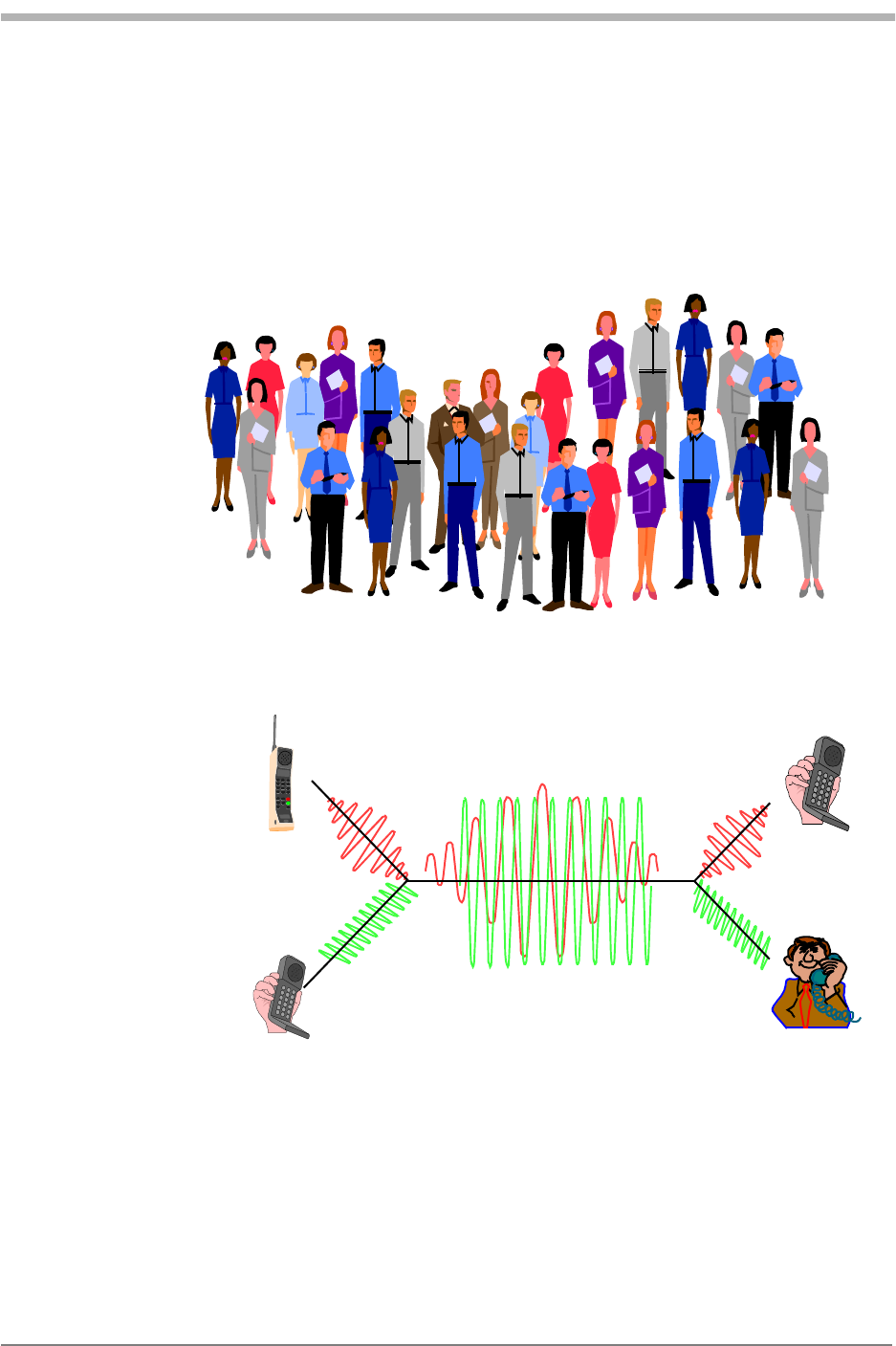
4 Kyocera 200 Module Data Book Kyocera Proprietary
`aj^=~åÇ=`Éääìä~ê=cìåÇ~ãÉåí~äë UOJjUUSOJN=oÉîK=MMP
disturbances. Delayed signals caused by multipath are separately received and
combined in CDMA.
`Éääìä~ê=ÑêÉèìÉåÅó=êÉìëÉ=é~ííÉêåë
One of the major capacity gains with CDMA is from its frequency reuse
efficiency. To eliminate interference from adjacent cells, narrowband FM systems
must physically separate cells using the same frequency. Complex frequency
reuse planning must be done in such a system to maximize capacity while
“Hello”
“Bonjour” “Shalom”
“Buenos Dias”
“Guten Tag”
Common Frequency Channel
red code
green code green code
red code
HI
GO
H
G
I
O
HI
GO
`aj^=ÅçÅâí~áä=é~êíó=Éñ~ãéäÉ
eçï=`aj^=ïçêâë

CDMA and Cellular
Fundamentals
Kyocera Proprietary Kyocera 200 Module Data Book 5
UOJjUUSOJN=oÉîK=MMP `aj^=~åÇ=`Éääìä~ê=cìåÇ~ãÉåí~äë
eliminating interference. A reuse pattern for analog and time division multiple
access (TDMA) systems employs only one-seventh of the available frequencies in
any given cell. With CDMA, the same frequencies are used in all cells and can be
used in all sectors of all cells.
This reuse is possible because CDMA is designed to decode the proper signal in
the presence of high interference. Adjacent cells using the same frequency in
CDMA simply cause an apparent increase in the channel background noise. By
allowing the use of the same frequencies in every cell, CDMA has approximately
six times the capacity of existing analog cellular systems.
`aj^=ÅçåÅÉéí
CDMA starts with a narrowband signal. Through specialized codes this spreads to
a bandwidth of 1.23 MHz. The ratio of the spread data rate to the initial data rate
is called the processing gain. For IS-95 standard CDMA with an 8 kbps vocoder,
the processing gain is 21 dB. When transmitted, a CDMA signal experiences high
levels of interference dominated by the coded signals of other CDMA users. This
takes two forms:
Interference from other users in the same cell
Interference from adjacent cells
The total interference also includes background noise and other spurious signals.
When the signal is received, the correlator recovers the desired signal and rejects
the interference. The correlators use the processing gain to pull the desired
signal out of the noise. Since a signal-to-noise ratio of 7 dB is required for
acceptable voice quality, this leaves 14 dB of extra processing gain to extract the
desired signal from the noise. This is possible because the interference sources
are uncorrelated (orthogonal in the case of the forward link).
`aj^=îÉêëìë=~å~äçÖ=cj
CDMA channels are defined by various digital codes as well as by frequency.
The capacity for CDMA is soft, not rigid. In analog systems, when all available
channels are in use, no further calls can be added. Capacity in CDMA can be
increased with some degradation of the error rate or voice quality, or can be
increased in a given cell at the expense of reduced capacity in the surrounding
cells.
Another advantage of CDMA is the use it makes of diversity. There are three types
of diversity:
Spatial diversity
Frequency diversity
Time diversity

6 Kyocera 200 Module Data Book Kyocera Proprietary
`aj^=~åÇ=`Éääìä~ê=cìåÇ~ãÉåí~äë UOJjUUSOJN=oÉîK=MMP
pé~íá~ä=ÇáîÉêëáíó
Spatial diversity takes two forms:
Two antennas
The base station uses two receive antennas for greater immunity to fading.
This is the classical version of spatial diversity. AMPS analog cellular base stations
use this type of diversity for improved fading resistance.
Multiple base stations
Multiple base stations simultaneously talk to the mobile phone during soft
handoff.
cêÉèìÉåÅó=ÇáîÉêëáíó
Frequency diversity is inherent in a spread-spectrum system. A fade of the entire
signal is less likely than with narrowband systems. Fading is caused by reflected
images of an RF signal arriving at the receiver such that the phase of the delayed
(reflected) signal is 180° out of phase with the direct RF signal.
Since the direct signal and the delayed signals are out of phase, they cancel each
other, causing the amplitude seen by the receiver to be greatly reduced. In the
frequency domain, a fade appears as a notch and is on the order of one over the
difference in the arrival time of two signals. For a 1 µsec delay, the notch is
approximately 1 MHz wide.
The Telecommunications Industry Association (TIA) CDMA system prescribes a
1.23 MHz bandwidth, so only those multipaths of time less than 1 µsec actually
cause the signal to experience a deep fade. In many environments, the multipath
signals arrive at the receiver after a much longer delay, causing only a narrow
portion of the signal to be lost. In a fade 20 to 200 kHz wide, this results in the
complete loss of an analog or TDMA signal but only reduces the power in a
portion of a CDMA signal. As the spreading width of a CDMA signal increases, so
does its multipath fading resistance.
qáãÉ=ÇáîÉêëáíó
Time diversity is a technique common to most digital transmission systems.
Signals are spread in time through interleaving. Interleaving the data improves
the performance of the error correction by spreading errors over time.
Errors in the real world during radio transmission usually occur in clumps, so
when the data is de-interleaved, the errors are spread over a greater period of
time. This allows the error correction to fix the resulting smaller, spread-out
errors. Forward error correction is applied, along with maximal likelihood
detection. The particular scheme used for CDMA is convolutional encoding in
the transmitter with Viterbi decoding using soft decision points in the receiver.
Another form of time diversity occurs in the base station when transmitting at
reduced data rates. When transmitting at a reduced data rate, the base station

CDMA and Cellular
Fundamentals
Kyocera Proprietary Kyocera 200 Module Data Book 7
UOJjUUSOJN=oÉîK=MMP `aj^=~åÇ=`Éääìä~ê=cìåÇ~ãÉåí~äë
repeats the data resulting in full rate transmission. The base station also reduces
the transmitted power when it operates at reduced data rates. This added
redundancy in the transmitted signal results in less interference (power is
lowered) and improves the CDMA mobile station receiver performance during
high levels of interference.
póåÅÜêçåáò~íáçå
For any direct sequence spread spectrum radio system to operate, all mobiles and
base stations must be precisely synchronized. If they are not synchronized, it
becomes nearly impossible to recover the codes used to identify individual radio
signals. Precise synchronization also leads to other benefits:
It allows such services as precise location reporting for emergency or travel
usage.
It allows the use of rake receivers for improved reception in multipath fading
conditions.
o~âÉ=êÉÅÉáîÉê
Instead of trying to overpower or correct multipath problems, CDMA takes
advantage of the multipath to provide improved reception quality. CDMA does
this by using multiple correlating receivers and assigning them to the strongest
signals. This is possible because the CDMA mobile is synchronized to the serving
base station. The mobile receiver can distinguish between direct and reflected
(multipath) signals because of the time delay in receiving the reflected signals.
Special circuits called searchers are also used to look for alternate multipaths and
for neighboring base station signals. The searchers slide around in time until they
find a strong correlation with their assigned code. Once a strong signal is located
at a particular time offset, the search assigns a receiver element to demodulate
that signal. The mobile receiver uses three receiving elements, and the base
station uses four. This multiple correlator system is called a rake receiver.
As conditions change, the searchers rapidly reassign the rake receivers to handle
new reception conditions. While each signal being processed by an individual
rake receiver experiences fading, the fades are independent because different
path lengths are experienced by each signal. Thus the receiver can coherently
recombine the outputs of the three rake receivers to reconstruct a much more
robust version of the transmitted signal. In this way, CDMA uses multipath signals
to create a more robust receiver. The rake receivers also allow soft handoff as one
or more receivers can be assigned to another base station.
There are some limitations to this scheme. If strong, short transmission paths are
present, such as in a very narrow canyon, the rake receiver system cannot
function. If the arrival time of a multipath signal is less than one clock cycle of
the CDMA system, the rake receiver cannot tell the difference between direct
and reflected signals. It has been found, however, that in real world situations

8 Kyocera 200 Module Data Book Kyocera Proprietary
`aj^=~åÇ=`Éääìä~ê=cìåÇ~ãÉåí~äë UOJjUUSOJN=oÉîK=MMP
longer time-delayed signals coexist when very strong short multipath signals are
present. This allows the searchers to find these other longer delayed signals
under these difficult propagation conditions.
`aj^=êÉîÉêëÉ=äáåâ=éçïÉê=Åçåíêçä
One of the fundamental enabling technologies of CDMA is power control. Since
the limiting factor for CDMA system capacity is the total interference, controlling
the power of each mobile is critical to achieve maximum capacity. CDMA
mobiles are power controlled to the minimum power that provides acceptable
quality for the given conditions. As a result, all mobile signals arrive at the base
station at approximately equal levels. In this way, the interference from one unit
to another is held to a minimum.
Two forms of power control are used for the reverse link:
Open loop power control
Closed loop power control
léÉå=äççé=éçïÉê=Åçåíêçä
Open loop power control is based on the similarity of the loss in the forward
path to the loss in the reversed path. (Forward refers to the base-to-mobile link,
while reverse refers to the mobile-to-base link.)
Open loop power control sets the sum of transmit power and receive power to a
constant, nominally -73 dBm (IS-98-A). A reduction in signal level at the receive
antenna results in an increase in signal power from the transmitter. For example,
when the received power from the base station is -85 dBm, this is the total
energy received in the 1.23 MHz receiver bandwidth. It includes the composite
signal from the serving base station as well as from other nearby base stations on
the same frequency.
The open loop transmit power setting for a received power of -85 dBm would be
+12 dBm. By the IS-98 specification, the open loop power control slew rate is
limited to match the slew rate of closed loop power control directed by the base
station. This eliminates the possibility of a sudden transmission of excessive
power by the open loop power control in response to a receiver signal-level
dropout.
`äçëÉÇ=äççé=éçïÉê=Åçåíêçä
Closed loop power control is used to allow the power from the mobile unit to
deviate from the nominal as set by open loop control. This is done with a form of
delta modulation. The base station monitors the power received from each
mobile station and commands the mobile to either raise power or lower power
by a fixed step of 1 dB. This process is repeated 800 times per second, or every
1.25 msec.

CDMA and Cellular
Fundamentals
Kyocera Proprietary Kyocera 200 Module Data Book 9
UOJjUUSOJN=oÉîK=MMP `aj^=~åÇ=`Éääìä~ê=cìåÇ~ãÉåí~äë
The power control data sent to the mobile from the base station is added to the
data stream by replacing the encoded voice data. This process is called
“puncturing” because the power control data is written into the data stream by
overwriting the encoded voice data. The power control data occupies 103.6 µsec
of each 1.25 msec of data transmitted by the base station.
Because the mobile’s power is controlled no more than is needed to maintain the
link at the base station, a CDMA mobile typically transmits much less power than
an analog phone. The base station monitors the received signal quality 800 times
per second and directs the mobile to raise or lower its power until the received
signal quality is adequate. This operating point varies with propagation
conditions, the number of users, and the density and loading of the surrounding
cells.
Analog cellular phones must transmit enough power to maintain a link even in
the presence of a fade. Analog phones usually transmit excess power. CDMA
radios are controlled in real time and kept at a power level that maintains a
quality transmission based on the changing RF environment. The benefits include
longer battery life and smaller, lower cost amplifier design.
jçÄáäÉ=éçïÉê=ÄìêëíáåÖ
Each 20 msec frame in IS-95 is divided into 16 power control groups. When the
mobile transmits, each power control group contains 1536 data symbols (chips)
at a rate of 1.2288 Mbps. When the vocoder moves to a lower data rate, the
CDMA mobile bursts its output by sending only the appropriate number of
power control groups. For example, transmitted groups are randomized to
spread the transmitted power over time. For each lowering of the data rate, the
transmitted power is reduced by 3 dB.
`aj^=ëóëíÉã=íáãÉ
As mentioned earlier, both mobiles and base station in direct sequence CDMA
must be synchronized. In the IS-95 system, synchronization is based on the
Global Positioning System (GPS) time. Each CDMA base station incorporates a
GPS receiver to provide exact system timing information for the cell. The base
station then sends this information to each mobile via a special channel. In this
manner, all radios in the system can maintain near-perfect synchronization.
Most designs also include atomic clocks to provide a backup timing reference.
These are capable of maintaining synchronization for up to several hours. The
GPS clock used for CDMA system time is then used to drive the long code
pseudo-random sequence generator.
`äçëÉÇ=äççé=éçïÉê=Åçåíêçä=éìåÅíìêáåÖ
Once the data has been scrambled with the user-specific long code, the closed
loop power control data is then punctured into the data stream. Power control

10 Kyocera 200 Module Data Book Kyocera Proprietary
`aj^=~åÇ=`Éääìä~ê=cìåÇ~ãÉåí~äë UOJjUUSOJN=oÉîK=MMP
bits are sent every 1.25 msec—once in every power control group (a CDMA
frame is 20 msec, with each frame having 16 1.25 msec power control groups).
Since the power control bits replace the encoded voice data, holes (missing data)
are introduced into the data stream from the receiver’s point of view. These holes
are accepted and the system uses the Viterbi decoder in the receiver to restore
the data lost by puncturing. The recovery of the missing data uses some of the
available processing gain in the system. The resulting loss of capacity has been
accounted for in the system’s design.
Another way to think of this is that slightly more power is required to maintain
the link because of the missing data introduced by the power control
puncturing. The power control data is sent only once in the 14.4 kbps case since
the reduced processing gain results in higher power being transmitted from the
base station to maintain an acceptable signal-to-noise ratio. The higher power
results in a much lower symbol error rate and the need to send the power control
data twice is eliminated.
t~äëÜ=ÅçÇÉ=ëéêÉ~ÇáåÖ
In the forward channel (cell-site-to-mobile), the Walsh codes provide a means for
uniquely identifying each user. A Walsh code generator provides 1 of the 64
codes to scramble the encoded voice data.
Walsh code 0 = pilot channel
Walsh code 32 = synchronous channel
Walsh code 1 to 7 = paging channels
Other Walsh codes = forward paging channel
oÉëéêÉ~ÇáåÖ=íÜÉ=ëÜçêí=ëÉèìÉåÅÉ
If all cells used the same 64 Walsh codes without another layer of scrambling, the
resulting interference would severely limit the system capacity.
Since all cells can use the same frequency (frequency domain), and all cells use
the same Walsh codes (code domain), the only other means to allow cells to
reuse the same Walsh codes is by using time offset (time domain). This final layer
of scrambling uses another code called the short code to allow reuse of the
Walsh codes and to provide a unique identifier to each cell.
Because everything in CDMA is synchronized to system time, it is possible to
have each cell site identified by using a time offset in the short sequence. These
“PN offsets” are separated by multiples of 64 1.2288 Mbps clock chips. This
allows for 512 unique time offsets for cell identification (32768 bits/64 bits = 512
offsets). By scrambling the Walsh encoded channels with the short code, each
base station can reuse all 64 Walsh codes and be uniquely identified from other
adjacent cells using the same frequency.

CDMA and Cellular
Fundamentals
Kyocera Proprietary Kyocera 200 Module Data Book 11
UOJjUUSOJN=oÉîK=MMP `aj^=~åÇ=`Éääìä~ê=cìåÇ~ãÉåí~äë
cçêï~êÇ=äáåâ=ÅÜ~ååÉä=Ñçêã~í
The base station transmitter signal is the composite of many channels (with a
minimum of four). The pilot channel is unmodulated (Walsh code 0); it consists
of only the final spreading sequence (short sequences). The pilot channel is used
by all mobiles linked to a cell as a coherent phase reference and also provides a
means for mobiles to identify cells from each other. The other three channels are:
Sync channel
Paging channel
Traffic channel
These channels use the same data flow, but different data are sent on each
channel.
póåÅ=ÅÜ~ååÉä
The sync channel transmits time-of-day information. This allows the mobile and
base to align clocks, which form the basis of the codes that are needed by both to
make a link. Specifically, one message sent by the sync channel contains the state
of the long code feedback shift registers 320 msec in the future. By reading this
channel, the CDMA mobile can load the data into its long code generator, and
then start the generator at the proper time. Once this has been accomplished,
the CDMA mobile has achieved full synchronization. The sync channel always
uses Walsh code channel 32.
m~ÖáåÖ=ÅÜ~ååÉä
The paging channel is the digital control channel for the forward link. Its
complement is the access channel, which is the reverse link control channel.
One base station can have multiple paging channels and access channels if
needed. Up to seven Walsh code channels can be allocated for use as paging
channels. The first paging channel is always assigned to Walsh code 1. When
more paging channels are required, Walsh codes 2 through 7 are used.
qê~ÑÑáÅ=ÅÜ~ååÉä
The traffic channel is equivalent to the analog voice channel. This is where actual
conversation takes place. The remaining Walsh codes are assigned to traffic
channels as required. At least 55 Walsh codes are available for use as traffic
channels. The actual number that can be used is determined by the total
interference levels experienced in any given cell. Nominal full loading would
typically be around 30 traffic channels in use for equally loaded cells.
Once all of the various channels are Walsh modulated, they are converted into I/
Q format, re-spread with the I and Q short sequences, low pass filtered to
reduced occupied bandwidth, and converted into analog signals. The resulting
analog I and Q signals from all channels are summed together and then sent to
the I/Q modulator for modulation into an RF carrier.

12 Kyocera 200 Module Data Book Kyocera Proprietary
`aj^=~åÇ=`Éääìä~ê=cìåÇ~ãÉåí~äë UOJjUUSOJN=oÉîK=MMP
`aj^=êÉîÉêëÉ=äáåâ=éÜóëáÅ~ä=ä~óÉê
The CDMA reverse link uses a different coding scheme to transmit data. Unlike
the forward link, the reverse link does not support a pilot channel for
synchronous demodulation (since each mobile station would need its own pilot
channel). The lack of a pilot channel is partially responsible for the reverse link’s
lower capacity than the forward link. In addition, Walsh codes cannot be used for
channelization since the varying time delays from each mobile to the base station
destroys the orthogonality of the Walsh codes. (Varying arrival time makes the
Walsh codes non-orthogonal.)
Since the reverse link does not benefit from non-interfering channels, this
reduces the capacity of the reverse link when compared to the forward link (all
mobiles transmitting interfere with each other). To aid reverse link performance,
the 9600 bps voice data uses a one-third (1/3) rate convolutional code for more
powerful error correction. For the 14,400 bps vocoder, the convolutional
encoder is only a half rate encoder that doubles the data rate. Thus the data rate
coming out of the convolutional encoder is the same for either the 9.6 or
14.4 Kbps voice channels. Then, six data bits at a time are taken to point at one
of the 64 available Walsh codes. The data, which is at 307.2 Kbps, is then XOR’ed
with the long code to reach the full 1.2288 Mbps data rate. This unique long
code is the channelization for the reverse link.
oÉîÉêëÉ=Éêêçê=éêçíÉÅíáçå
To improve the performance of the reverse link, a more powerful convolution
encoder is used. The third-rate encoder used in the reverse link outputs three
9600 bps data streams when driven with a single 9600 data stream. This provides
increased error correction capability, but also increases the data rate to 28,800
bps.
SQJ~êó=ãçÇìä~íáçå
Walsh codes are not used to provide the channelization in the reverse link. In the
reverse link they are used to randomize the encoded voice data with a
modulation format that is easy to recover. Each six serial data bits output from
the convolutional encoder are used to point to one of the 64 available Walsh
codes (26 = 64). This modulation has the effect of increasing the data rate 10.67
times to 307 Kbps. As the incoming voice data changes, a different Walsh code is
selected. Since this type of modulation can output one of 64 possible codes, it is
referred to as 64-ary modulation.
oÉîÉêëÉ=ÅÜ~ååÉä=äçåÖ=ÅçÇÉ=ëéêÉ~ÇáåÖ
The channelization in the reverse link must provide for unique code assignments
for each operational phone. Walsh codes could not be used for the reverse
channelization, since they would not provide enough unique channels. Since the
long code is 42 bits in length, this allows 242 (4.3 billion) unique channel
assignments. Thus the long code imprinted with your unique mask is used to

CDMA and Cellular
Fundamentals
Kyocera Proprietary Kyocera 200 Module Data Book 13
UOJjUUSOJN=oÉîK=MMP `aj^=~åÇ=`Éääìä~ê=cìåÇ~ãÉåí~äë
provide the channelization in the reverse link. This allows all mobiles in even
very large systems to have unique channel assignments. Since the long codes are
simply uncorrelated and not orthogonal to each other, the recovery and
demodulation process is more difficult for CDMA base stations. The high-speed
searcher circuits in the base station let it quickly search over the wide range of
long codes to lock on a particular user’s signal. These modules represent a good
design trade-off, since it is more feasible to design complex hardware/software
into a base station than into a mobile phone.
Reverse channel short sequence spreading
CDMA mobiles use the same pseudo-random number (PN) sequences as the base
for final short sequence scrambling. An extra one half period clock delay in the
mobile’s Q channel produces offset quadrature phase shift keying (QPSK)
modulation rather than straight QPSK modulation. Thus mobiles can use a
simpler and more efficient power amplifier design. Offset QPSK modulation
prevents the signal from going to zero magnitude and greatly reduces the
dynamic range of the modulated signal. Less costly amplifiers can be used on
CDMA mobiles because of the reduced linear dynamic range obtained with offset
QPSK modulation.
`aj^=íìêåJçå=éêçÅÉëë
póëíÉã=~ÅÅÉëë
When the mobile is first powered on, it must find the best base station. This is
similar to analog, where the phone scans all control channels and selects the best
one. In CDMA, the mobile unit scans for available pilot signals, which are all on
different time offsets. This process is made easier because of the fixed nature of
these offsets.
The timing of any base station is always an exact multiple of 64 system clock
cycles (called chips) offset from any other base station. The mobile selects the
strongest pilot tone and establishes a frequency and time reference from this
signal. The mobile then demodulates the sync channel, which is always on Walsh
code 32. This channel provides master clock information by sending the state of
the 42 bit long code shift register 320 ms in the future. Once the mobile has read
the sync channel and established system time, the mobile uses the parameters
from the sync channel to determine the long code mask being used by the cell
site it is acquiring.
póåÅ=ÅÜ~ååÉä=ãÉëë~ÖÉ
The sync channel messages contains:
CDMA protocol revision supported by the cell site
Minimum protocol revision supported by a CDMA mobile to work with the cell
site

14 Kyocera 200 Module Data Book Kyocera Proprietary
`aj^=~åÇ=`Éääìä~ê=cìåÇ~ãÉåí~äë UOJjUUSOJN=oÉîK=MMP
System and network identification numbers for the cell site
PN offset of the cell site
Paging channel data rate
Timing parameters – including such items as local time offset from system time
and a flag for indicating if daylight savings time is active in the area
oÉ~Ç=íÜÉ=é~ÖáåÖ=ÅÜ~ååÉä
At this point the mobile demodulates the paging channel and decodes all of the
data contained in the various messages supplied on the paging channel. If
required by the parameters on the paging channel, the phone then registers with
the base station. If the phone is a slotted mode phone, it must first register with
the base station before it can be paged.
The slotted paging channel mode lets the phone save power by going to sleep
and only awakening when it is time to check for a page from the base station.
During registration, the time slot for the phone to wake up and listen is
negotiated between the base and mobile. Once this is completed, the phone is
ready to place or receive phone calls.
m~ÖáåÖ=ÅÜ~ååÉä=ãÉëë~ÖÉë
The paging channel is the heart of a CDMA base station. All parameters and
signaling necessary for the proper operation of a CDMA cell site are handled by
the paging channel. The paging channel supports a number of distinct messages
that provide information and send messages.
The system parameters message provides the mobile with system information
such as the network, system and base station identification numbers, the number
of paging channels supported, registration information, and the soft handoff
thresholds.
The access parameters message provides information to the mobile that dictates
the behavior of access probes when a CDMA mobile initiates a call.
The neighbor list message tells the mobile that the PN offsets of surrounding cell
sites may become likely candidates for soft handoffs.
The CDMA channel list reports the number of CDMA frequencies supported by
the cell site as well as the configuration of surrounding cell sites.
The slotted and non-slotted page messages lets the cell site page CDMA phones
for incoming calls. CDMA mobiles operating in the slotted mode must first
register with the cell site before they can be paged. This registration is required
to establish which slot is used by the cell site to transmit the page to the mobile.
The channel assignment message is used to communicate the information
needed to get the mobile onto a traffic channel.

CDMA and Cellular
Fundamentals
Kyocera Proprietary Kyocera 200 Module Data Book 15
UOJjUUSOJN=oÉîK=MMP `aj^=~åÇ=`Éääìä~ê=cìåÇ~ãÉåí~äë
Other supported messages on the paging channel include various types of
signaling messages and authentication.
`aj^=áÇäÉ=ëí~íÉ=Ü~åÇçÑÑ
The mobile has searchers scanning for alternative pilot channels at all times. If a
pilot channel is found from another base station that is strong enough for a link,
the mobile requests a soft handoff if it crosses into a new zone. In this case, the
CDMA cells must have commanded the CDMA mobile to perform zone-based
registration to reregister the phone.
`aj^=Å~ää=áåáíá~íáçå
Keying in a phone number and pressing the Send key initiates an access probe.
The mobile uses a special code channel called the access channel to make
contact with the cell site. CDMA mobiles can transmit two types of channels on
the single physical channel provided by the reverse link. These two channels are
distinguished by the types of coding used.
The access channel is used by the mobile to initiate calls. The other possible
channel is the traffic channel, which is used once a call is established. The long
code mask used for access probes is determined from parameters obtained from
the sync and paging channels. The parameters are the access channel number,
the paging channel number, the base station ID, and the pilot PN offset used by
the base station.
Before a link is established, closed-loop power control is not active. The mobile
uses open-loop control to estimate an initial level. Multiple tries are allowed, with
random times between the tries to avoid collisions that can occur on the access
channel. For each cell site there is also a limited number of supported access
channels, again to reduce the odds of collisions because of the limited number of
access channel receivers in the base station.
`aj^=Å~ää=ÅçãéäÉíáçå
After each access attempt, the mobile listens to the paging channel for a
response from the base station. If the base station detects the access probe from
the mobile, it responds with a channel assignment message. This message
contains all of the information required to get the mobile onto a traffic channel.
This message includes such information as the Walsh code channel to be used for
the forward traffic channel, the frequency being used, and the frame offset to
indicate the delay between the forward and reverse links.
Once the mobile has acknowledged the channel assignment message, the base
station initiates the land link and the mobile moves from the access channel to
the traffic channel. To accommodate signaling, IS-95 supports two methods for
temporarily grabbing the traffic channel:

16 Kyocera 200 Module Data Book Kyocera Proprietary
`aj^=~åÇ=`Éääìä~ê=cìåÇ~ãÉåí~äë UOJjUUSOJN=oÉîK=MMP
Blank and burst signaling
Dim and burst signaling
Both are similar except that the blank and burst steals a contiguous block of
frames to transmit signaling messages, while dim and burst reduces the vocoder
rate and then uses the remaining traffic channel time to more slowly send
signaling messages.
^jmp=ÅÉääìä~ê=çîÉêîáÉï
The cellular radio frequency spectrum has been divided by the Federal
Communications Commission (FCC) into two equal segments or bands to allow
two independent cellular carriers to coexist and compete in the same geographic
coverage area. Each band occupies one half of the available channels in the
cellular spectrum. Initially, there are 832 channels.
To guarantee nationwide compatibility, the signaling channel frequencies have
been preassigned to each segment (band). The two bands and their assigned
channels are defined as follows:
`çåíêçä=EÇ~í~F=ÅÜ~ååÉäë
A cellular telephone in the cellular system is under the indirect control of the
switch, or central controller. The central controller uses dedicated control
channels to provide the signaling required to establish a telephone call. Control
channels are used to send and receive only digital data between the base station
and the cellular telephone.
Voice channels are used for both audio and signaling once a call is established.
The 21 control channels in each band may be dedicated according to access and
paging channels. The data on the forward control channel generally provides
some basic information about the particular cellular system, such as the system
ID and the range of channels to scan to find the access and paging channels.
A Band Channels
Primary Control Channels (21): 313 - 333
Secondary Control Channels (21): 688 - 708
Voice Channels (395): 001 - 312, 667 - 716, and
991 - 1023
B Band Channels
Primary Control Channels (21): 334 - 354
Secondary Control Channels (21): 737 - 757
Voice Channels (395): 355 - 666 and 717 - 799

CDMA and Cellular
Fundamentals
Kyocera Proprietary Kyocera 200 Module Data Book 17
UOJjUUSOJN=oÉîK=MMP `aj^=~åÇ=`Éääìä~ê=cìåÇ~ãÉåí~äë
Access channels are used to respond to a page or originate a call. The system and
the cellular telephone use access channels where two-way data transfer occurs to
determine the initial voice channel.
Paging channels, if used, are the normal holding place for the idle cellular
telephone. When a call is received at the central controller for a cellular
telephone, the paging signaling occurs on a paging channel.
In many systems both control channel functions are served by the same control
(access) channel for a particular cell. Only in very high density areas is multiple
control (paging) channels required.
sçáÅÉ=ÅÜ~ååÉäë
Voice channels are primarily used for conversation, with signaling being
employed as necessary to handle cell-to-cell handoffs, output power control of
the cellular radio-telephone, and special local control features. Data from the cell
site (known as FORWARD DATA) and data from the mobile or portable (known as
REVERSE DATA) is sent using frequency shift keying. In AMPS signaling, various
control and response tones are used for a variety of applications to be described
later.
páÖå~äáåÖ=éêçíçÅçä
In 1983, when the Federal Communications Commission (FCC) licensed cellular
telephony, the signaling protocol used was AMPS. The AMPS signal protocol, an
invention of Bell Labs, was ultimately adopted by all governments in the western
hemisphere and eventually several other governments throughout the world.
Under the original AMPS protocol there were 21 control channels assigned to
each of two possible carriers in any metropolitan area, with a total of 333
channels assigned to each carrier. Prior to 1987 the FCC had allocated 312
channels to voice (voice, DTMF, or data) applications for each carrier. In 1987 the
FCC expanded the cellular spectrum (Expanded Spectrum) from a total of 666
channels to 832 channels, allowing for an increase of 83 voice channels for each
carrier. But the number of control channels remained constant, with 21 control
channels for each carrier. Each control channel had a bandwidth of 30 kHz and
used the signaling protocol.
páÖå~äáåÖ=íçåÉ=EpqF
In AMPS, signaling tone is a 10 kHz signal used by the mobile or portable on the
reverse voice channel (REVC) to signal certain activities or acknowledge various
commands from the cell site, including handoffs, alert orders, and call
terminations, and to indicate switch-hook operation.