Kyocera KWC-M200 Transmitter Module User Manual Kyocera 200 Module Data Book
Kyocera Communications, Inc Transmitter Module Kyocera 200 Module Data Book
Kyocera >
Contents
user guide2
Module Developer’sKit
Kyocera Proprietary Kyocera 200 Module Data Book 61
12
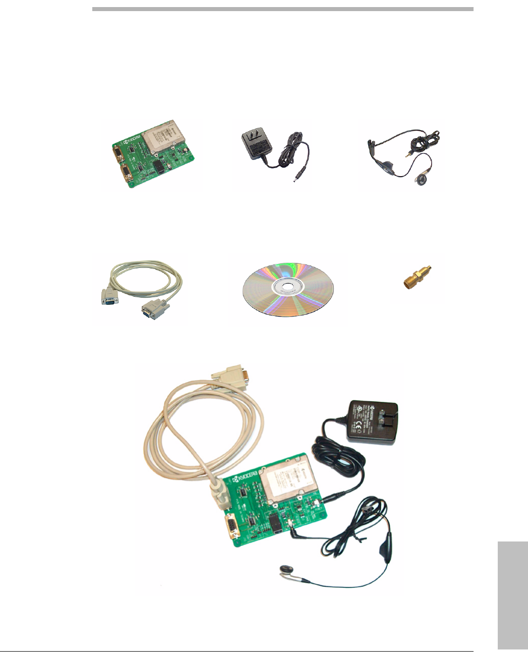
Module Developer’sKit
The Module Developer’s Kit (MDK) is used to assist in development of end-user
applications for the CDMA Module. The MDK facilitates integration through the
serial and digital codec pulse code modulation (PCM) interface options. Contents
of the MDK are illustrated below.
Module and Travel Charger* Audio Headset*
9-pin RS 232
Cable Assembly* Module Documentation
CD-ROM
MMCX-to-SMA
Adapter (qty: 2)
* Kit may include alternate components.
Interface Board
(qty: 2)

62 Kyocera 200 Module Data Book Kyocera Proprietary
Module Developer’sKit 82-B7907-1 Rev. 005
It should be clearly understood that the software in the MDK (specifically, the
code in the Kyocera 200 Module User’s Guide, 82-B7908-1) is provided for
sample purposes only. The MDK software is not warranted as the basis for a
deployed implementation.

Warranty and Product
Support
Kyocera Proprietary Kyocera 200 Module Data Book 63
13
Warranty and Product Support
The KWC CDMA Module Developer’s Kit arrives having been tested as described
in the Module Testing & Integration chapter. Testing should be duplicated at the
integrator’s/customer’s facility. KWC can provide advice as to the type of test
equipment needed.
This Module testing should be separate from the testing to be performed on the
end product (with the Module installed). KWC offers a warranty for the CDMA
Module, from the date of shipment from KWC’s facility. This warranty provides
the customer with a remedy for defective Modules within the warranty period
and subject to all other warranty provisions.
KWC requests that the integrator retain several Modules as backup in case of
failure. It is assumed that you maintain a first level of returned Module testing in
your QA department prior to returning the Module to KWC. This alleviates the
question of whether the failure is in the Module or the end product. “No trouble
found” (NTF) occurrences on Modules returned to KWC will result in fees. KWC
reserves the right, at its own discretion, to repair, replace, or issue a trade credit
for any defective Module under warranty.
Warranty repair excludes warranty claims on products that have been subject to
misuse, neglect, improper storage or installation, or that have been repaired,
modified, or altered by a facility other than a KWC-authorized service center or a
KWC-certified repair center. In all cases, the final testing of the KWC line is the
sole controlling determination of Module performance.

Mechanical
SpecificationsMechanical
SpecificationsMechanical
SpecificationsMechanical
SpecificationsMechanical
Specifications
Kyocera Proprietary Kyocera 200 Module Data Book 65
14
Mechanical Specifications
Mating connectors
The following connectors mate with the Module.
lModule Interface Connector Mate
Manufacturer: MOLEX Inc., www.molex.com
Manufacturer’s Part Number: 54230-0509
Kyocera MCN: 449-24545-0509
lModule RF Connector Mate
Standard MMCX plug, available from
several manufacturers including Amp,
Radiall, and Telegartner
Drawings The following technical drawings are included in this chapter:
lLand pattern and pin assignment for Module interface mating connector
lMounting hole and land pattern placement guidelines with recommended
mounting hardware
lModule overall dimensioned drawing
lModule exploded view
66 Kyocera 200 Module Data Book Kyocera Proprietary
Mechanical Specifications 82-B7907-1 Rev. 005
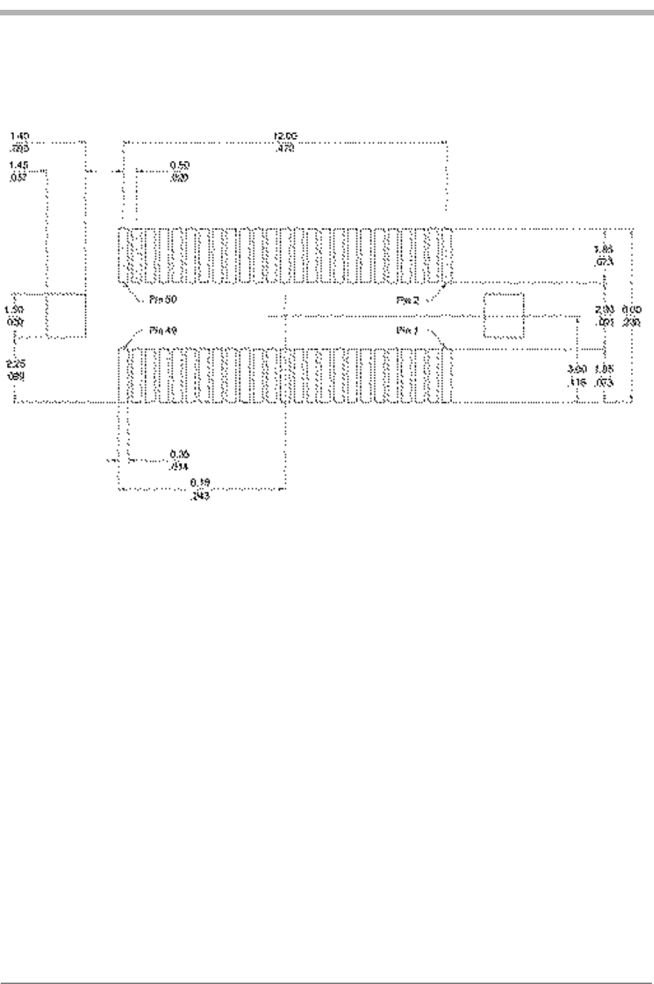
Land pattern and pin assignment for the Module interface mating connector
Mechanical
SpecificationsMechanical
SpecificationsMechanical
SpecificationsMechanical
SpecificationsMechanical
Specifications
Kyocera Proprietary Kyocera 200 Module Data Book 67
82-B7907-1 Rev. 005 Mechanical Specifications
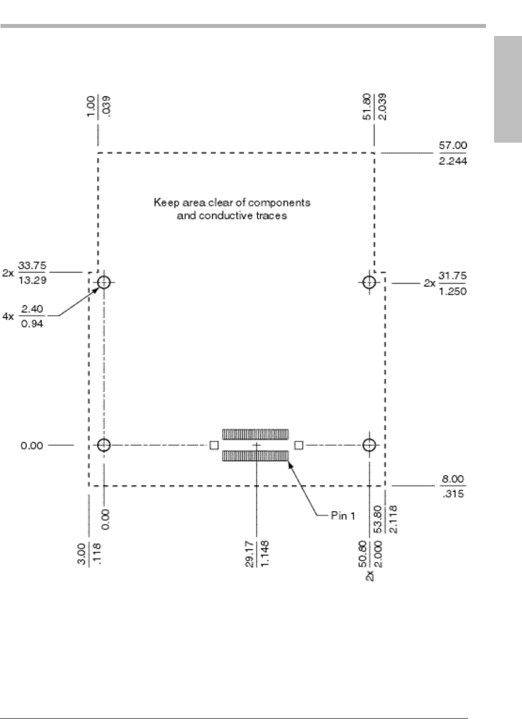
Mounting hole and land pattern placement guidelines
68 Kyocera 200 Module Data Book Kyocera Proprietary
Mechanical Specifications 82-B7907-1 Rev. 005
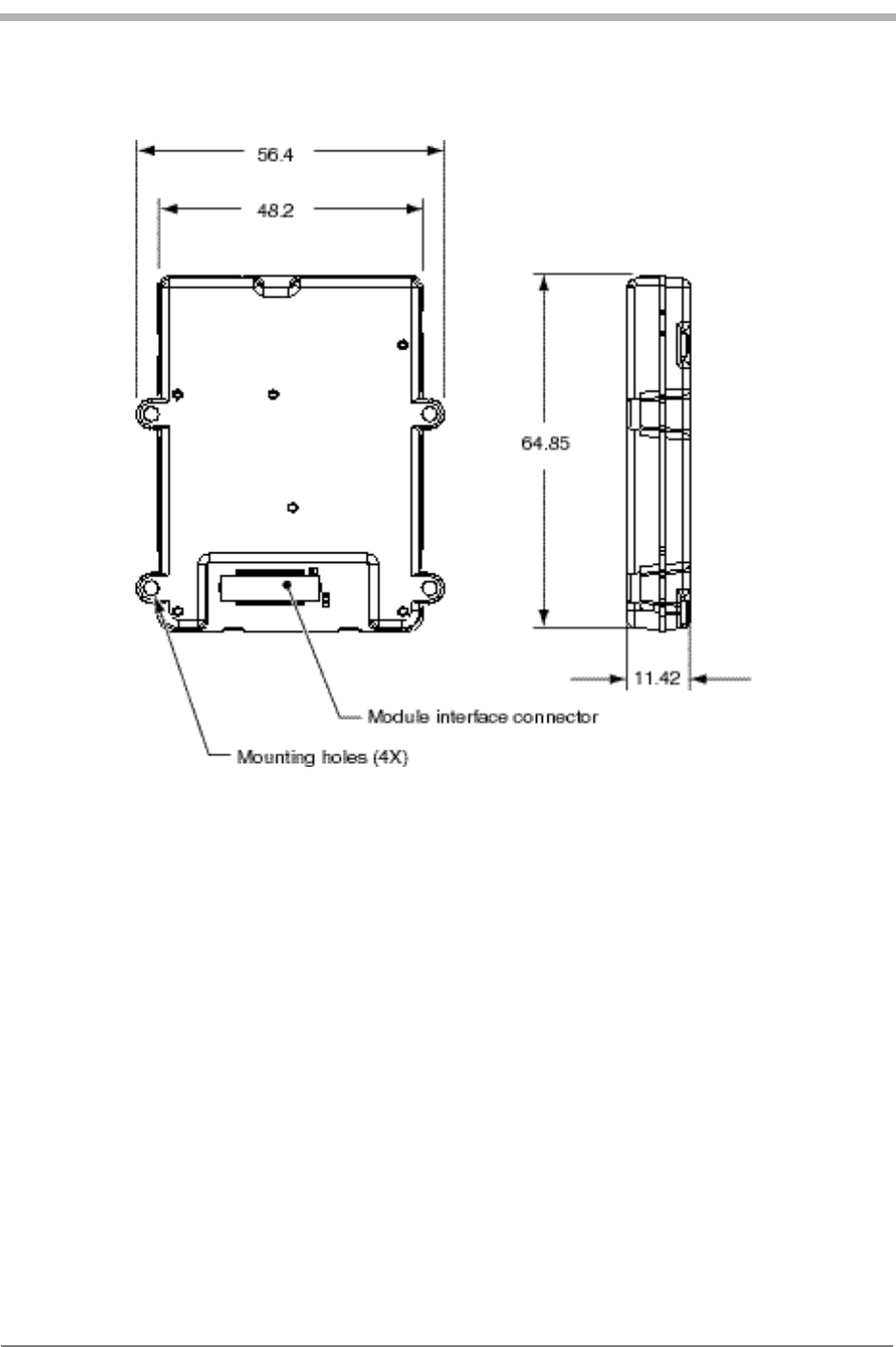
Module outside dimensions (mm)
Mechanical
SpecificationsMechanical
SpecificationsMechanical
SpecificationsMechanical
SpecificationsMechanical
Specifications
Kyocera Proprietary Kyocera 200 Module Data Book 69
82-B7907-1 Rev. 005 Mechanical Specifications
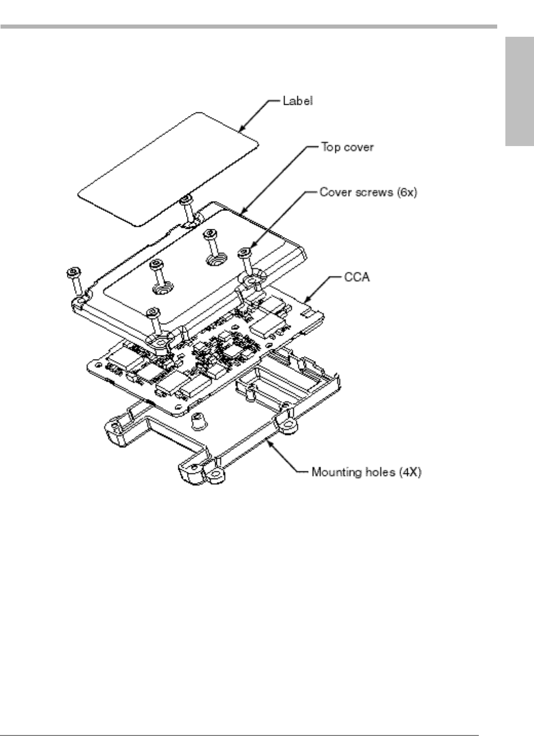
Module exploded view

70 Kyocera 200 Module Data Book Kyocera Proprietary
Mechanical Specifications 82-B7907-1 Rev. 005
Assignments and Signal
DefinitionsAssignments and Signal
DefinitionsAssignments and Signal
DefinitionsAssignments and Signal
DefinitionsAssignments and Signal
Definitions
Kyocera Proprietary Kyocera 200 Module Data Book 71
15
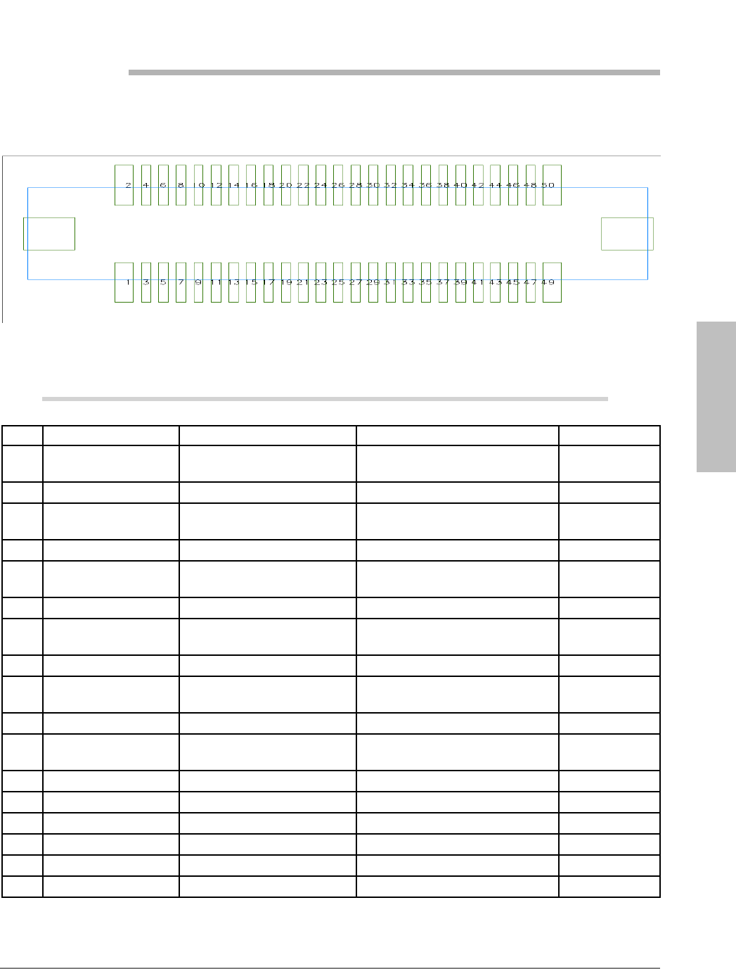
Assignments and Signal Definitions
50-pin Module interface connector pin assignments (viewed looking down on connector)
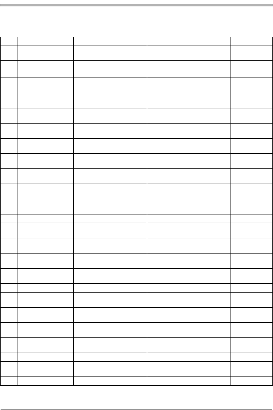
Signal definitions of 50-pin Module interface connector
Pin # Signal Name Comment Modem Signal Level
1VPH_PWR Power to the CDMA
transceiver 3.6 VDC min to 4.2 VDC max Power input(6)
2GND Signal and power return GROUND
3VPH_PWR Power to the CDMA
transceiver 3.6 VDC min to 4.2 VDC max Power input(6)
4GND Signal and power return GROUND
5VPH_PWR Power to the CDMA
transceiver 3.6 VDC min to 4.2 VDC max Power input(6)
6GND Signal and power return GROUND
7VPH_PWR Power to the CDMA
transceiver 3.6 VDC min to 4.2 VDC max Power input(6)
8GND Signal and power return GROUND
9VPH_PWR Power to the CDMA
transceiver 3.6 VDC min to 4.2 VDC max Power input(6)
10 GND Signal and power return GROUND
11 VEXT# Indicates that external
power is being used 0 to VPH_PWR max Analog control
12 N/C No connection
13 N/C No connection
14 LED_EN# Enable external LED 0 to VPH_PWR max Analog control
15 N/C No connection
16 LED_DRV External LED drive 10 mA LED drive Analog output
17 N/C No connection
72 Kyocera 200 Module Data Book Kyocera Proprietary
Assignments and Signal Definitions 82-B7907-1 Rev. 005
18 XCVR_DET Indicates that transceiver
is on Digital output(2)
19 N/C No connection
20 N/C No connection
21 XCVR_EN# CDMA transceiver primary
power enable 0 to VPH_PWR max Analog input
22 MSM_DP_TXD UART1 - transmit data VOH(min) = 2.4V,
VOL(max) = 0.5V Digital output(1)
23 MSM_DP_RXD UART1 - receive data VIH(min) = 1.9V,
VIL(max) = 0.9V Digital input(2)
24 MSM_DP_CTS# UART1 - clear to send VIH(min) = 1.9V,
VIL(max) = 0.9V Digital input(2)
25 MSM_DP_RTS# UART1 - ready for receive VOH(min) = 2.4V,
VOL(max) = 0.5V Digital output(1)
26 MSM_DP_DTR# UART1 - data terminal
ready VIH(min) = 1.9V,
VIL(max) = 0.9V Digital
input(2,3)
27 MSM_DP_RI# UART1 - ring indicator VOH(min) = 2.4V,
VOL(max) = 0.5V Digital output(1)
28 MSM_DP_DCD# UART1 - data carrier detect VOH(min) = 2.4V,
VOL(max) = 0.5V Digital output(1)
29 HS_PRES# Headset detection input to
MSM VIH(min) = 1.9V,
VIL(max) = 0.9V Digital
input(2,3)
30 GND Signal and power return GROUND
31 MSM_DP_TXD2 UART2 - transmit data VOH(min) = 2.4V,
VOL(max) = 0.5V Digital output(1)
32 MSM_DP_RXD2 UART2 - receive data VIH(min) = 1.9V,
VIL(max) = 0.9V Digital input(2)
33 MSM_DP_CTS2# UART2 - clear to send VIH(min) = 1.9V,
VIL(max) = 0.9V Digital input(2)
34 MSM_DP_RTS2# UART2 - ready for receive VOH(min) = 2.4V,
VOL(max) = 0.5V Digital output(1)
35 GND Signal and power return GROUND
36 CAR_SCL Analog Carkit SCL line VOH(min) = 2.4V,
VOL(max) = 0.5V Input/output
37 CAR_SDA Analog Carkit SDA line VOH(min) = 2.4V,
VOL(max) = 0.5V Input/output(1)
38 CAR_MIC+ Analog carkit microphone
input VIH(min) = 1.9V,
VIL(max) = 0.9V Analog input(2)
39 CAR_SPKR+ Analog Carkit Speaker
output VOH(min) = 2.4V,
VOL(max) = 0.5V Analog
output(1)
40 GND Signal and power return GROUND
41 HS_SPEAKER Headset speaker audio
output 1.5Vpp, 8.8mW into 32 ohm
load Analog
output(1)
42 GND Signal and power return GROUND
Signal definitions of 50-pin Module interface connector
Pin # Signal Name Comment Modem Signal Level
Assignments and Signal
DefinitionsAssignments and Signal
DefinitionsAssignments and Signal
DefinitionsAssignments and Signal
DefinitionsAssignments and Signal
Definitions
Kyocera Proprietary Kyocera 200 Module Data Book 73
82-B7907-1 Rev. 005 Assignments and Signal Definitions
43 MAIN_MIC+ Main microphone positive
input 1.8VDC nominal, -3Mv rms Electret
microphone
input(4)
44 MAIN_MIC- Handset microphone
negative terminal GROUND
45 GND Signal and power return GROUND
46 EAR_SPKR+ Main speaker positive
audio output 1.2VDC nominal,
3V pp with pin 47 Bridge amp
output(5)
47 EAR_SPKR- Main speaker negative
audio terminal 1.2VDC nominal,
3V pp with pin 46
48 HS_MIC+ Headset microphone input 1.8VDC nominal, ~3Mv rms Electret
microphone
input(4)
49 GND Ground for headset
microphone GROUND
50 LSPKR_ON Loudspeaker amp control
output VOH(min) = 2.4V,
VOL(max) = 0.5V Digital output(2)
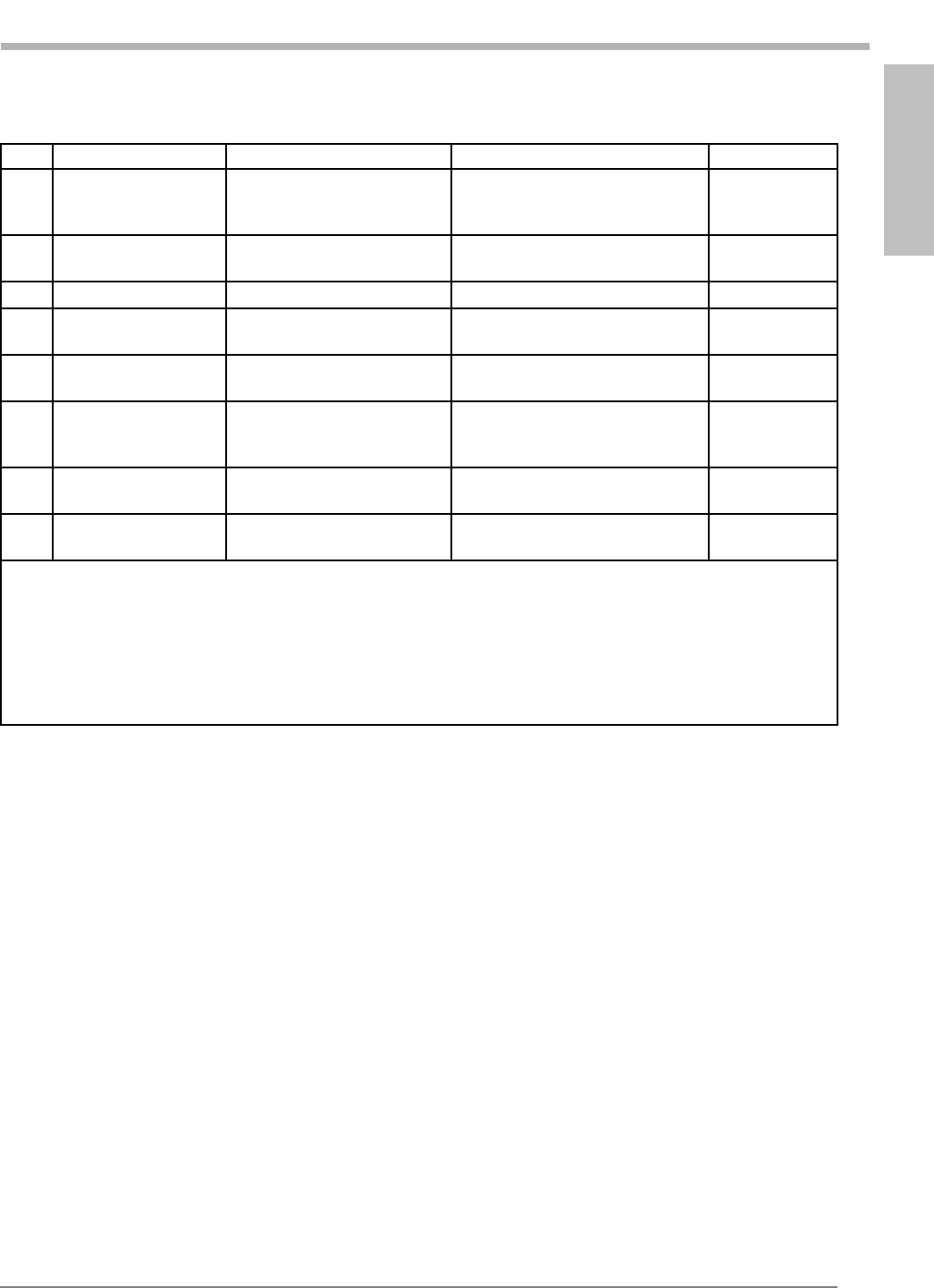
Notes:
1. Input connected directly to MSM. Do not exceed V(max) of 3.1V; damage to MSM may result.
2. Output connected directly to MSM. Do not exceed V(max) of 2.8V; damage to MSM may result.
3. 10K ohm pull-up resistor inside Module.
4. Input for standard electret microphone. 1.8V supplied via 2.2K ohm resistor inside Module.
5. Pins 46 and 47 are bridge (differential) amp outputs capable of driving 35 mW into a 32 ohm speaker
connected between these pins.
6. 1200 mA required for full analog transmission capabilities.
Signal definitions of 50-pin Module interface connector
Pin # Signal Name Comment Modem Signal Level

74 Kyocera 200 Module Data Book Kyocera Proprietary
Assignments and Signal Definitions 82-B7907-1 Rev. 005

Module Developer’s Kit
SchematicModule Developer’s Kit
SchematicModule Developer’s Kit
SchematicModule Developer’s Kit
SchematicModule Developer’s Kit
Schematic
Kyocera Proprietary Kyocera 200 Module Data Book 75
16
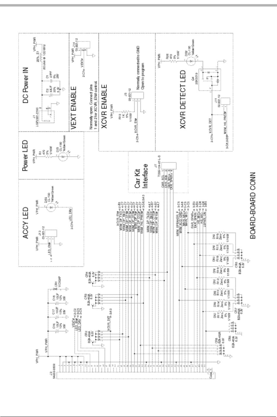
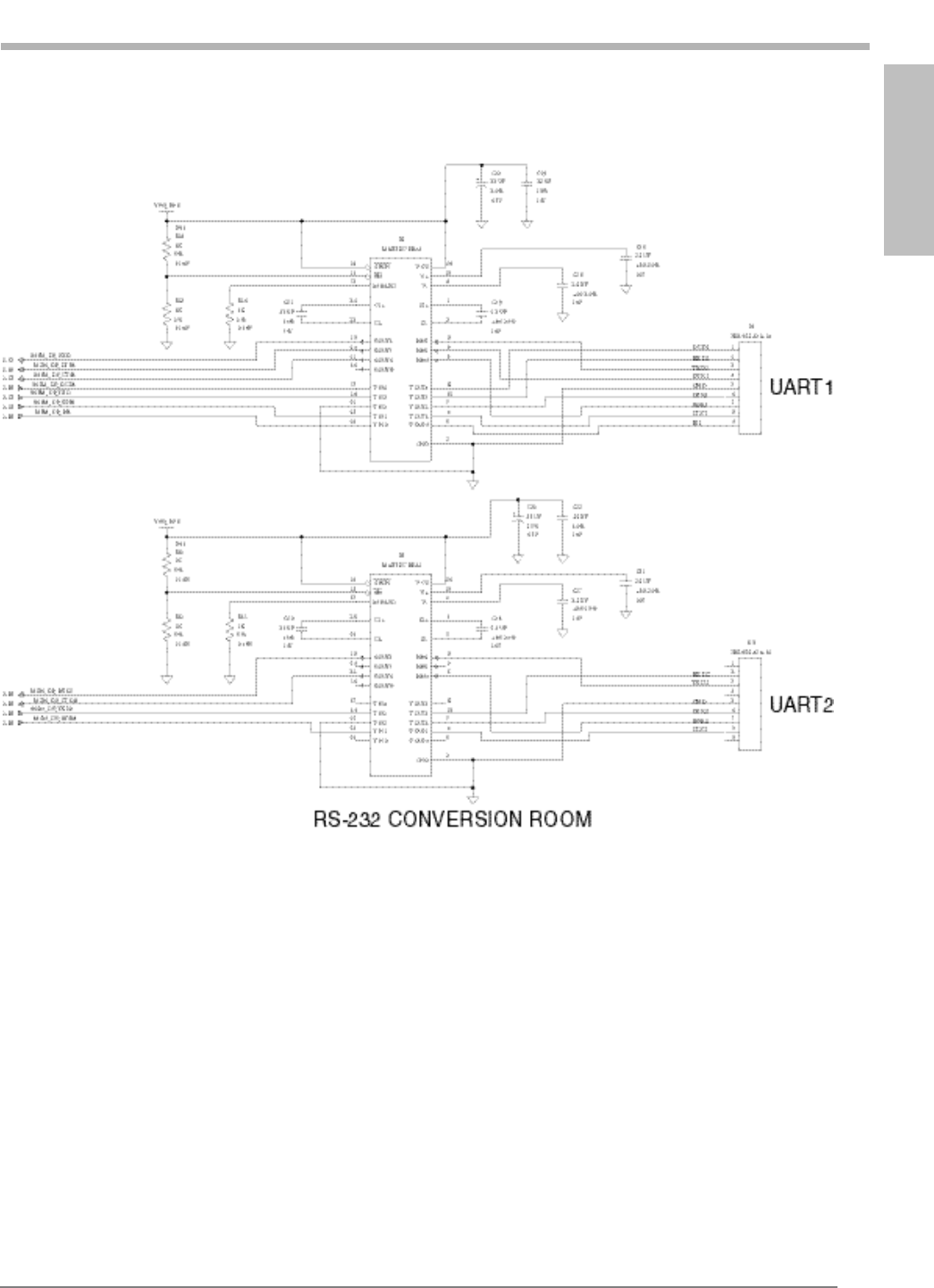
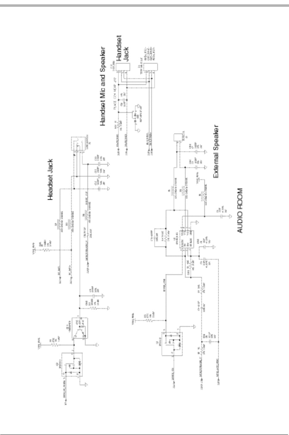
Module Developer’s Kit Schematic
This chapter contains schematic views of the current Module Developer’s Kit
(MDK), which is identified on the board as K4021. Kyocera Wireless Corp. has
also produced limited quantities of an earlier version, identified as K4020.
Differences between the two are listed below.
lThe K4020 does not contain J14, VEXT_EN jumper.
lIn the schematic for K4020, signal LED_EN# was labeled LED_EN.
lIn the K4020, DS3 cathode is connected to ground and anode is connected to
LED_DRV.
lIn the K4020, R10 is 1.1 KΩ.
76 Kyocera 200 Module Data Book Kyocera Proprietary
Module Developer’s Kit Schematic 82-B7907-1 Rev. 005
Module Developer’s Kit
SchematicModule Developer’s Kit
SchematicModule Developer’s Kit
SchematicModule Developer’s Kit
SchematicModule Developer’s Kit
Schematic
Kyocera Proprietary Kyocera 200 Module Data Book 77
82-B7907-1Rev. 005 Module Developer’s Kit Schematic
78 Kyocera 200 Module Data Book Kyocera Proprietary
Module Developer’s Kit Schematic 82-B7907-1 Rev. 005

How to Set up Data Calls
Kyocera Proprietary Kyocera 200 Module Data Book 79
17
How to Set up Data Calls
This chapter explains how to set up your Module to make data calls using
Microsoft Windows. Understanding these methods may help you integrate the
Module with your Remote System.
The Module can make three types of data calls:
lAsync data calls
l1X packet data service
lQuickNet Connect (a packet-like data service)
Getting started
1. Verify that you have correctly set up your Module.
2. Ensure that Windows Dial-Up Networking or other point-to-point protocol
(PPP) compatible dial-up software is installed on your computer.
3. Ensure that terminal emulation software such as HyperTerminal or
ProComm™ is installed on your computer.
4. Connect a serial cable from the UART 1 on the CDMA Module Developer’s
Kit interface board to an enabled communications port of your computer.
Installing the Kyocera Wireless serial modem driver
From the CD-ROM, run the program Kyocera-Module.exe. The INF folder will
automatically be copied to your hard drive and placed in the Windows folder.
Setting up your Module as a wireless modem
1. Open the Windows Control Panel and double-click the Modems or Phone
and Modem Options icon.
2. Click Add to add a new modem. If you have a PCMCIA card slot, click Other
and proceed to step 3. If you do not have a PCMIA card slot, go to step 3.
3. Click Don’t detect my modem. Select Kyocera Wireless Corp. from the
manufacturer list and select Kyocera CDMA High-Speed Wireless Modem.
4. Click Next.
5. Assign the modem to your configured COM port, then close Modem
Properties.

80 Kyocera 200 Module Data Book Kyocera Proprietary
How to Set up Data Calls 82-B7907-1 Rev. 005
Using terminal emulation software to talk to the modem in AT command
mode Set up the program for a new connection using the Kyocera CDMA High-Speed
Wireless Modem driver or by pointing to the serial port to which the Module is
connected with the following configuraiton.
Send AT commands to the Module to test the connection. The Module should
respond to an ATZ command with OK.
Making an async data call using terminal emulation software
1. Open the connection in the terminal emulation software.
2. Use the ATDT command to dial the phone number of another modem.
Making an async data call using dial-up networking
1. Open Dial-up Networking.
2. Double-click the Make New Connection icon.
3. Type a name for your new connection.
4. Select the installed modem and click Next.
5. Type the area code and telephone number of your ISP and click Next, then
Finish.
6. Right-click the New icon and select Properties.
7. From the Properties menu, configure Server Types for the appropriate
options and protocols. To increase connection speed, uncheck Log on to
network, NetBEUI, and IPX/SPX/Compatible.
Making a QuickNet Connect data call
1. Open the terminal mode of your terminal emulation software. Enter
AT$QCQNC=1 and QC$QCMDR=2 for a QuickNet Connect call.
Alternatively, configure the connection to bring up a terminal screen before
dialing to enter the AT commands.
2. Open Dial-Up Networking.
Bits per second: The default COM PORT SPEED of UART 1 is
115,200 bps
Data bits: 8
Parity: None
Stop bits: 1
Flow control: Hardware

How to Set up Data Calls
Kyocera Proprietary Kyocera 200 Module Data Book 81
82-B7907-1 Rev. 005 How to Set up Data Calls
3. Double-click the Make New Connection icon.
4. Type a name for your new connection.
5. Select your installed modem, then click Next.
6. Leave the area code blank and type #777 as the telephone number. Click
Next, then Finish.
7. Right-click the New icon and select Properties.
8. Click Server Types and check TCP/IP. Uncheck Log on to network, NetBEUI,
and IPX/SPX/Compatible.
9. You will need to get the name and password from the service provider to
authenticate to their network.
Making a 1XRTT packet data call
1. Open the terminal mode of your terminal emulation software. Enter
AT$QCQNC=0 and QC$QCMDR=3 for a 1XRTT call. Alternatively, configure
the connection to bring up a terminal screen before dialing to enter the AT
commands.
2. Open Dial-Up Networking.
3. Double-click the Make New Connection icon.
4. Type a name for your new connection.
5. Select your installed modem, then click Next.
6. Leave the area code blank and type #777 as the telephone number. Click
Next, then Finish.
7. Right-click the New icon and select Properties.
8. Click Server Types and check TCP/IP. Uncheck Log on to network, NetBEUI,
and IPX/SPX/Compatible.
9. You will need to get the name and password from the service provider to
authenticate to their network.
Helpful hints
lEnsure that the phone or CDMA Module is turned on and the cables are firmly
connected to a COM port.
lEnsure that the computer COM port is enabled and that no other equipment
is attached to the COM port.
lEnsure that no other application that uses the COM port is running.

82 Kyocera 200 Module Data Book Kyocera Proprietary
How to Set up Data Calls 82-B7907-1 Rev. 005
Troubleshooting
How do I get a phone number for my CDMA Module?
Contact your CDMA service provider for details. Once you have a phone
number, use the Phone Support Toolkit to program it into your Module.
How can I obtain technical support?
You can call us in the U.S. and Canada at 888-236-2746 and outside North
America at 858-882-1401. Our email address is
module-support@kyocera-wireless.com.