Kyocera KWC-M200 Transmitter Module User Manual 82 M8862 1
Kyocera Communications, Inc Transmitter Module 82 M8862 1
Kyocera >
Contents
manual part 3

Software Description
Kyocera Proprietary Kyocera 200 Module Data Book 43
UOJjUUSOJN=oÉîK=MMP pçÑíï~êÉ=aÉëÅêáéíáçå
oç~ãáåÖ=iáëí=bÇáíçê
This application displays a phone’s roaming protocol information.
`^fq=Eåçí=áåÅäìÇÉÇ=ïáíÜ=íÜÉ=jahF
The QUALCOMM QCTest™ CDMA Air Interface Tester (CAIT) is the enhanced
Windows version of QUALCOMM’s Mobile Diagnostic Monitor (MDM), which
has been used extensively worldwide to analyze over-the-air CDMA system
performance.
CAIT characterizes over-the-air CDMA cellular or PCS system performance by
measuring real-time, mobile-based CDMA RF performance as well as messaging
and protocols specified by IS-95, J-STD-008, CDMA2000, 1xEV-DO, and WCDMA
standards. CAIT displays subscriber station characteristics and can manipulate
QUALCOMM subscriber station data and functions. CAIT is designed to operate
using most handsets that contain QUALCOMM ASICs as well as all of
QUALCOMM’s test/trial phones. Whether conducting tests in the lab or in the
field, CAIT is a powerful tool to evaluate handset and network performance.
An alternative product is the Spirent Universal Diagnostic Monitor (UDM),
designed to monitor and analyze the performance of CDMA mobile devices and
networks.
Note Kyocera Wireless Corp. does not distribute or resell this software. Please contact QUALCOMM
Incorporated directly to obtain CAIT (http://www.qualcomm.com/qctest), or Spirent
Communications to obtain their UDM (http://www.spirentcom.com).

44 Kyocera 200 Module Data Book Kyocera Proprietary
pçÑíï~êÉ=aÉëÅêáéíáçå UOJjUUSOJN=oÉîK=MMP
Digital and Audio Signal
System Specifications
Kyocera Proprietary Kyocera 200 Module Data Book 45
V
aáÖáí~ä=~åÇ=^ìÇáç=páÖå~ä=
póëíÉã=péÉÅáÑáÅ~íáçåë
`aj^=íê~åëÅÉáîÉê=ëáÖå~ä=ÇÉÑáåáíáçåë
The signals fall into the following classifications.
Power
Serial port 1
Serial port 2
Analog audio and audio control
`áêÅìáíêó=ÇÉëÅêáéíáçå
mçïÉê=êÉèìáêÉãÉåíë
Power (+3.6 V to +4.2 VDC) is fed to the CDMA transceiver via the VPH_PWR
signal. This signal is fed from an external DC source.
Note There is no significant change in power consumption over the range of the supplied voltages with
the spec (+3.6 V - +4.2 VDC).
Power consumption, analog
Voice, while transmitting
Peak 1.1 A
Average 1.1 A
Power consumption, digital
Power
up*** Registration** Voice* CS
Data* Packet Data*+GPS*+
Peak 1300 mA 320 mA (duration
150 mS)
820 mA 410 mA 1150 mA
(duration 45 mS)
1220 mA
(duration 45 mS)
Average 130 mA 6 mA/9 mA** 288 mA 296 mA 705 mA 320-400 mA
* In CDMA, power consumption increases with distance from the base station. See “CDMA
reverse link power control” on page 8. Max power = 25 dBm.
** The Module needs to register only once. Standby (SCI=0) wakes up every 1.2 sec for
120 mS - 140 mA.
*** Duration 3.5 mS for capacitor charging
+ Reading at beginning of session

46 Kyocera 200 Module Data Book Kyocera Proprietary
aáÖáí~ä=~åÇ=^ìÇáç=páÖå~ä=póëíÉã=péÉÅáÑáÅ~íáçåë UOJjUUSOJN=oÉîK=MMP
There is no more than a 6% fluctuation on current consumption over the specified temperature
range (-30 to +60C).
The above numbers are worst-case. We tested based on maximum current, max/min
temperature, and max/min voltage conditions, so the designer can expect to encounter these
values only the the worst environments (margin +/- 3%).
The Kyocera 200 Module User’s Guide, 82-B7908-1, describes the method for
bringing the CDMA transceiver to the full power-up mode. MDK users can also
power up by placing a jumper across pins 2 and 3 of J5 (XCVR_EN#).
qê~åëÅÉáîÉê=Éå~ÄäÉ=~åÇ=ÉñíÉêå~ä=éçïÉê
There are two ways to enable the module, transceiver enable (XCVR_EN#), and
external power detection (VEXT#). To use external power detection, the VEXT#
signal is pulled low. In this mode, the Module will power on whenever
VPH_PWR is applied. There is a pull-down resistor on VEXT#, so external power
is the default setting. To use XCVR_EN#, the VEXT# signal must be pulled up to
VPH_PWR. The use of these signals is described in the Kyocera 200 Module
User’s Guide, 82-B7908-1.
To use the Module as a full CDMA transceiver, a jumper should be placed over
pins 2 and 3 of J5. (Note that the small white dot indicates pin 1.) To program the
Module using the MDK and appropriate service programming tools, the jumper
must be removed.
qê~åëÅÉáîÉê=ÇÉíÉÅíáçå
The signal XCVR_DET is used to detect that the Module is powered on. This is a
digital signal wth a maximum current (source or sink) of 1 mA. This signal has a
maximum output voltage of 2.85 V. See the Kyocera 200 Module User’s Guide,
82-B8908-1, for more detail on the use of this signal.
iba
The Module contains circuitry to drive an external LED. A separate enable signal
(LED_EN#) is used to enable the drive circuit. The output signal (LED_DRV)
should be connected to the cathode of the LED. The drive current is set at 10 mA
and can be used to drive multiple LEDs. Since LED_EN# is pulled up to
VPH_PWR on the Module, an open collector enable circuit is recommended. If
this circuit is not used, both pins should not be connected.
pÉêá~ä=éçêí=ëáÖå~äë
The CDMA transceiver digital circuitry is powered from a 2.85 V supply. A series
resistor or other latchup control mechanism placed at the receiver inputs of the
CDMA transceiver prevents CMOS latchup due to differing supply voltages and
ground bounce.
A CMOS logic high level corresponds to a data link mark or one level. A CMOS
logic low level corresponds to a data link space or zero level. The data rate of this

Digital and Audio Signal
System Specifications
Kyocera Proprietary Kyocera 200 Module Data Book 47
UOJjUUSOJN=oÉîK=MMP aáÖáí~ä=~åÇ=^ìÇáç=páÖå~ä=póëíÉã=péÉÅáÑáÅ~íáçåë
serial interface is up to 230.4 Kbps. There shall be eight data bits, no parity, and
at least one stop bit.
The maximum digital signal voltage levels for both serial ports are shown in
Notes 1 and 2 in the Signal Definition Table in Chapter 15.
pÉêá~ä=éçêí=N
These data signals between the CDMA transceiver and the MDK form a full
duplex asynchronous serial port with CMOS levels. The port is used to pass data
for standard modem functions. These signals are present on the MDK and are
referred to as UART1.
The signals are standard RS-232 signals as listed below.
MSM_DP_TXD
MSM_DP_RXD
MSM_DP_CTS#
MSM_DP_RTS#
MSM_DP_DTR#
MSM_DP_RI#
MSM_DP_DCD#
pÉêá~ä=éçêí=O
These data signals between the CDMA transceiver and the MDK form a full
duplex asynchronous serial port with CMOS levels. These signals are present on
the MDK and are referred to as UART2
The signals are a subset of the standard RS-232 signals as listed below.
MSM_DP_TXD2
MSM_DP_RXD2
MSM_DP_CTS2#
MSM_DP_RTS2#
^ìÇáç=ÅáêÅìáíêó=ÇÉëÅêáéíáçå
The Module contains complete audio circuitry to allow you to complete the
cellular telephone circuits in analog form. The analog form uses the traditional
microphone input and speaker output.
The analog circuits are intended for a very simple, non-echo-canceling
environment. The analog audio portion of the board has been carefully designed
so that you can interface with the module and maintain the very highest audio
quality. It is strongly recommended that the user device carefully isolate the
audio circuits and grounds from all other sources of noise in the system.

48 Kyocera 200 Module Data Book Kyocera Proprietary
aáÖáí~ä=~åÇ=^ìÇáç=páÖå~ä=póëíÉã=péÉÅáÑáÅ~íáçåë UOJjUUSOJN=oÉîK=MMP
On the speaker side, the output is driven directly from the codec differential
outputs and can drive a 1500 ohm circuit. It is suggested that you buffer this
signal with an external amplifier for driving lower impedance devices. If the
external circuits are differential, then you should connect to both SPKR+ and
SPKR-. If the external circuits are single-ended, then you should connect to
SPKR+ and leave SPKR- floating.
The microphone inputs, MIC+ and MIC-, are differential inputs intended for use
with a standard condensing microphone. If the user device has a single-ended
output from microphone circuits, then MIC+ should be used for the input signal
to the module and MIC- should be connected to AUDIO_GND.
^ìÇáç=ÅáêÅìáíë
The Module provides raw low-level audio signals to the 50-pin module connector
(see Chapter 14). These signals are amplified on the MDK board. End users
needing audio should use audio circuits similar to those shown in Chapter 14.
^å~äçÖ=~ìÇáç=~åÇ=~ìÇáç=Åçåíêçä
On the CDMA transceiver, the audio signals connect directly to the differential
audio signals on the MSM5100. The signals are:
EAR_SPKR+, EAR_SPKR- (Connect 32 ohm or greater earpiece receiver across
these lines.)
MAIN_MIC+, MAIN_MIC- (Mic 1)
HS_SPEAKER
HS_MIC+ (Mic 2)
An additional signal called LSPKR_ON is present on the board-to-board connector
and could be used to enable an audio amplifier on the MDK board if that is
needed in the future. Another signal, HS_PRES#, is used to indicate to the CDMA
transceiver that a headset has been connected to the MDK. The MDK currently
has an open drain output that is pulled up through a resistor on the CDMA
transceiver. When this signal goes low, it means a headset has been connected to
the headset jack on the MDK.
The MDK audio circuits are optimized for the devices specified below.
Microphone
Sensitivity: -45 +/-3 dB @ 1 kHz (0 dB = 1 V/Pa) RL = 2 kohms Vcc = 2 V
Ear speaker
Impedance: 32 ohms @ 1 kHz
Sensitivity (at 1 mW/1 kHz): 105 +/-3 dB

Radio Frequency
System Specifications
Kyocera Proprietary Kyocera 200 Module Data Book 49
NM
o~Çáç=cêÉèìÉåÅó=póëíÉã=
péÉÅáÑáÅ~íáçåë
jçÇìäÉ=~åíÉåå~=ëéÉÅáÑáÅ~íáçåë
Two 50 ohm coaxial RF connectors are provided for Module testing and
integration into an end user device. One connector is for GPS RF only; the other
is for the Module’s tri-mode (PCS/cellular CDMA/AMPS) RF. The OEM developer
must provide a suitable antenna that works in the desired frequency band of
operation. The table below provides the Module’s conducted receive and
transmit capabilities measured at the RF connectors The antenna gain should be
designed using the conducted performance as a guideline toward meeting the
radiated system requirements. (See Chapter 14, “Mechanical Specifications,” on
page 75 for RF connector detail.)
Kyocera 200 Module conducted requirements and typical performance
* With assistance
pí~åÇ~êÇë
The Kyocera 200 Module meets or exceeds the following air interface standards
and minimum performance standards except as noted in the applicable
“Specification exceptions” section in this chapter.
pí~åÇ~êÇë=ëéÉÅáÑáÅ=íç=UMM=jeò
TIA/EIA IS-95-A
Mobile Station – Base Station Compatibility Requirements for Dual-Mode
Wideband Spread Spectrum Cellular System
Parameter Minimum Module
Requirement
Typical Module performance
at 25C
GPS receiver sensitivity -147 dBm < -149 dBm*
PCS receiver sensitivity -104 dBm < -106.5 dBm
Cell CDMA receiver
sensitivity
-104 dBm < -107 dBm
AMPS receiver sensitivity -116 dBm < -118.5 dBm
PCS max transmit power 22.5 dBm 23 dBm
Cell CDMA max transmit
power
23.5 dBm 24 dBm
AMPS max transmit
power
26 dBm 26.5 dBm

50 Kyocera 200 Module Data Book Kyocera Proprietary
o~Çáç=cêÉèìÉåÅó=póëíÉã=péÉÅáÑáÅ~íáçåë UOJjUUSOJN=oÉîK=MMP
TIA/EIA TSB-74
Support for 14.4 Kbps Data Rate and PCS Interaction for Wideband Spread
Spectrum Cellular System
pí~åÇ~êÇë=ëéÉÅáÑáÅ=íç=NVMM=jeò
ANSI J-STD-008
Personal Station – Base Station Compatibility Requirements for 1.8 to 2.0 GHz
CDMA PCS
ANSI J-STD-018
Recommended Minimum Performance Requirements for 1.8 to 2.0 GHz CDMA
Personal Stations
pí~åÇ~êÇë=~ééäáÅ~ÄäÉ=íç=ÄçíÜ=UMM=jeò=~åÇ=NVMM=jeò
CDG Ref. Document 27
High Rate Speech Service Option for Wideband Spread Spectrum Communication
Systems
TIA/EIA IS-96-A
Speech Service Option 1 Standard for Dual-Mode Wideband Spread Spectrum
Cellular Systems
TIA/EIA IS-125
Recommended Minimum Performance Standards for Digital Cellular Wideband
Spread Spectrum Speech Service Option 1
TIA/EIA IS-126-A
Mobile Station Loopback Service Option Standard
QUALCOMM Document: 80-12918-1, Rev. X3
Markov Service Options for Wideband Spread Spectrum Communications
Systems
TIA/EIA IS-637-A
Short Message Service (partial support)
TIA/EIA IS-707A
Packet data, circuit-switched data and digital fax capabilities as described in this
document
TIA/EIA IS-98-D
Recommended Minimum Performance Requirements for Dual-Mode Wideband
Spread Spectrum Cellular Mobile Stations

Radio Frequency
System Specifications
Kyocera Proprietary Kyocera 200 Module Data Book 51
UOJjUUSOJN=oÉîK=MMP o~Çáç=cêÉèìÉåÅó=póëíÉã=péÉÅáÑáÅ~íáçåë
TIA-916
Recommended Minimum Performance Specification for TIA/EIA/IS-801-1 Spread
Spectrum Mobile Stations
TIA/EIA IS-2000, release 0
Introduction to cdma2000 Standards for Spread Spectrum Systems
péÉÅáÑáÅ~íáçå=ÉñÅÉéíáçåë
The Kyocera 200 Module performs to the specifications except as noted in this
section.
fåíÉêçéÉê~Äáäáíó=äáãáí~íáçå
All components of the features listed in the previous section are not capable of
being tested for interoperability with current infrastructure equipment until such
time as commercially deployed infrastructure equipment supports all feature
components. Prior to such interoperability testing occurring, all CDMA modules
delivered by KWC may have the following exceptions.
Authentication
Reduced rate vocoder operation
fpJSPT=ëéÉÅáÑáÅ~íáçå=áãéäÉãÉåí~íáçå
The CDMA Module supports the following IS-637 features (mobile-terminated).
Cellular Paging Teleservice (CPT)
Cellular Messaging Teleservice (CMT)
Voice Mail Notification (VMN)
oc=ëóëíÉã=ëéÉÅáÑáÅ~íáçåë
The Kyocera 200 Module meets the IS-98 specification at 800 MHz, the
ANSI J-STD-0018 specification at 1900 MHz, and the TIA-916 GPS specification.
`aj^=êÉÑÉêÉåÅÉ=ã~íÉêá~ä=~åÇ=íê~áåáåÖ
The Telecommunication Industry Association (TIA) oversees the CDMA
standards. These documents are published and obtainable from:
Global Engineering
15 Inverness Way East
Inglewood, CO 80112
USA
800-854-7179
fax - 303-397-2740

52 Kyocera 200 Module Data Book Kyocera Proprietary
o~Çáç=cêÉèìÉåÅó=póëíÉã=péÉÅáÑáÅ~íáçåë UOJjUUSOJN=oÉîK=MMP
Global Engineering
Europe: Rapidoc (UK)
+44 1344 861 6666 rapidoc@techindex.co.uk
All CDMA devices that are activated on a service provider's network are expected
to comply with these various standards.
For information on CDMA worldwide, please visit the Web site for the CDMA
Development Group at http://www.cdg.org. The CDMA Development Group
(CDG) is a consortium of companies who have joined together to lead the
adoption and evolution of CDMA wireless systems around the world.

Module Testing and
Integration
Kyocera Proprietary Kyocera 200 Module Data Book 53
NN
jçÇìäÉ=qÉëíáåÖ=~åÇ=fåíÉÖê~íáçå
This chapter outlines the testing performed at KWC and the suggested testing
required by the customer. This test flow is part of the warranty/product support
plan that KWC uses for returned Modules.
ht`=jçÇìäÉ=éêçÇìÅíáçå=íÉëíáåÖ
The Module is assembled by using standard Surface Mount Technology (SMT)
and tested to verify functional performance.
It is anticipated that once the Module has been designed into the customer’s
units, the incoming QA test at the customer site should be able to determine that
the Module is meeting specifications.
`ìëíçãÉê=jçÇìäÉLÇÉîáÅÉ=íÉëíáåÖ
Customer testing of the Module is recommended to be done in two parts. The
customer is responsible for developing the test software and test flow at their
incoming QA receiving. KWC provides a basic specification, which describes a
set of tests to be performed, and suggests equipment and equipment settings to
test the Module to the pertinent specifications.
First, the customer tests RF specification-compliant Modules in developing the
incoming test software. This incoming testing can be reduced to a sample test as
required by the customer.
After this incoming test, the customer then assembles the Module into the OEM
device. During final testing, another final test station is used to test the Module
inside the device.
The test uses the 50 ohm connector and the same scripts used in the incoming
test station to see if the Module still performs to specification while in the OEM’s
device.
If this final test fails, it is the customer’s responsibility to use the incoming QA
test station to verify that the Module is either performing or not performing to
specification. If the Module fails this test, then it is returned to KWC as a non-
compliant device.

54 Kyocera 200 Module Data Book Kyocera Proprietary
jçÇìäÉ=qÉëíáåÖ=~åÇ=fåíÉÖê~íáçå UOJjUUSOJN=oÉîK=MMP
`aj^=íÉëí=ÉèìáéãÉåí=~åÇ=éêçÇìÅíë
Lease or purchase of test equipment is available from vendors who provide this
equipment for CDMA over-the-air simulation. Some suggested products include:
Hewlett Packard® HP-8924 CDMA Mobile Station Tester
Rohde & Schwarz CMU200 Radio Communication Tester
Tektronix® CMD-80 CDMA Mobile Station Tester
Agilent 8960 Series 10 E5515C CDMA Mobile Station Tester
Spectrum analyzer, RF power meter
CDMA Air Interface Tester (CAIT), available from QUALCOMM Incorporated
Windows-based program that generates real-time graphical displays that
illustrate radio frequency (RF) energy, multipath, transmit/receive power,
vocoder rate, frame error rate information, and system status.
This product requires the execution of the Test and Deployment Supply
Agreement with QUALCOMM.
Universal Diagnostic Monitor (UDM), available from Spirent plc
mêçÇìÅí=áåíÉÖê~íáçå
The Module is intended to be integrated into a customer device for provision of
voice and data capabilities as outlined in chapter “RF System Specifications.” The
Module is designed to be integrated by using a simple serial port for control and
call processing and a single RF connection using the 50 ohm connector. A second
50 ohm connector is used for GPS. All testing costs will be incurred by the
customer.
Note
The Module may require further shielding to pass FCC Part 15 in the device being built. The
customer is responsible for any further shielding.
The Module has been tested by integrating it into user equipment. The tests
indicated that the shielding provided on the Module is adequate to ensure that
the KWC Module does not prevent the customer from passing the FCC Part 15
testing if they shield their own device properly.
The customer’s final device needs to maintain the standards that the Module has
already passed in CDG Stage 1 and CDG Stage 2 certification tests. This device
also needs to pass CDG 3 certification with the carrier/service provider(s) that
the customer expects will provide service for the device once on the market.
These test costs are the responsibility of the customer.

Module Testing and
Integration
Kyocera Proprietary Kyocera 200 Module Data Book 55
UOJjUUSOJN=oÉîK=MMP jçÇìäÉ=qÉëíáåÖ=~åÇ=fåíÉÖê~íáçå
lîÉêîáÉï=çÑ=íÉëí=~åÇ=áåíÉÖê~íáçå=Ñäçï
This section outlines hardware integration and test steps an OEM of a Module
needs to address in order to verify performance of a KWC Module in an end
application.
fåíÉÖê~íáçå=íÉëíë
The Module has been tested for compliance to TIA/EIA IS-98-D or ANSI J-STD-
0018 (SP-3385) as a stand-alone device. Integration testing is required to assert
that these specifications are still met when the Module is operating in the end
application. Formal compliance to IS-98-D or J-STD-0018 is proven by doing
regression testing in the application device. The customer is ultimately
responsible for compliance of the application device.
^åíÉåå~=ã~íÅÜáåÖ
The Module has two 50 ohm coaxial RF connectors that can be mated with
suitable 50 ohm antennas that work in the desired frequency band of operation.
Antenna systems should be designed to ensure compliance with IS-98 and
J-STD-0018.
^ìÇáç=áåíÉÖê~íáçå
Performance of microphone and speaker transducers must be verified in the end
application. Module analog audio circuits have been verified in a typical portable
phone application.
The serial data, power supply/battery and the digital codec interfaces should be
integrated and verified for proper electrical performance.
jÉÅÜ~åáÅ~ä=~åÇ=ÉåîáêçåãÉåí~ä=íÉëíë
Modules are tested for compliance to environmental requirements typical for
cellular phones. Similar tests appropriate for use in the end application device
should be performed and would be the responsibility of the customer.
`adJNI=`adJOI=`adJP=
Modules are certified CDG-1 and certified with Lucent, Nortel, Motorola, and
Samsung infrastructure equipment to CDG-2 testing requirements agreed to by
the CDMA Development Group. Users may wish or be required to perform all or
a regression suite of these tests depending on the carrier network they use.
Standards also vary in some international markets. (Information on the CDMA
Development Group (CDG) is available at www.cdg.org.)
CDG-1 tests are performed in formal test labs of various members of the CDG.
CDG-1 tests verify compliance to either IS-98-D or J-STD-0018.

56 Kyocera 200 Module Data Book Kyocera Proprietary
jçÇìäÉ=qÉëíáåÖ=~åÇ=fåíÉÖê~íáçå UOJjUUSOJN=oÉîK=MMP
CDG-2 tests are performed on site at infrastructure equipment manufacturers
(arranged by the OEM developer). These tests verify interoperability with
infrastructure equipment. Tests are run using the RF test connector (not antenna
system).
CDG-2 tests verify compliance to CDG57 and IS-898.
CDG-3 tests are an end application test. These are over-the-air tests to verify
performance within a particular carrier’s network. The Module is not formally
tested in this manner. The OEM needs to perform this testing in coordination
with the carrier(s) they plan to utilize.
c``=Åçãéäá~åÅÉ
The equipment certifications appropriate to your device are marked on the
device and the accompanying product specification. Where appropriate, use of
the equipment is subject to the following conditions.
Caution The Kyocera 200 Module has been certified by the Federal Communications Commission
(“FCC”). Unauthorized modifications or changes not expressly approved by Kyocera Wireless
Corp. (“Kyocera”) could void compliance with regulatory rules, and thereby your authority to use
this equipment.
Caution Electromagnetic Interference (EMI): To avoid any harmful interference to radio communication
or any electronic equipment, it is a user’s responsibility to test the final product at a system level
and to ensure the final product is in compliance with Part 15 of the FCC rules. This test can be
performed by any FCC-certified test lab.
WARNING: To reduce any possible hazard due to exposure of the human body
to electromagnetic radiation, per FCC OET Bulletin 65, this device is approved
for operation using the antennas as described below. The antenna installation
must provide a separation distance of 20 cm or more between the antenna and
all persons to satisfy Maximum Permissible Exposure (MPE) compliance. This
installation limitation must be included in the integrator/Original Equipment
Manufacturer (“OEM”) user guide to alert users on FCC RF exposure compliance.
In order to fulfill the FCC certification requirements, the following requirements
must be complied with.
i~ÄÉäáåÖW
An FCC ID label is on the Module itself. The FCC label must be visible through a
window on the final device or it must be visible when an access panel, door, or
cover is easily removed. If not, a second label must be placed on the outside of
the final device containing the following text:
Contains “FCC ID: OVFKWC-M200”

Module Testing and
Integration
Kyocera Proprietary Kyocera 200 Module Data Book 57
UOJjUUSOJN=oÉîK=MMP jçÇìäÉ=qÉëíáåÖ=~åÇ=fåíÉÖê~íáçå
^åíÉåå~W
For FCC compliance, the Kyocera 200 Module has been tested with the approved
antennas listed below. At an OEM’s request and agreement to pay Kyocera for all
related costs, including but not limited to engineering costs, outside lab costs,
and FCC charges, Kyocera will consider adding new antennas to the current FCC
ID.
If Kyocera, in its discretion, agrees to test the Kyocera 200 Module with an
alternative antenna and the test is successful, Kyocera will then apply to the FCC
for a Class II Permissive Change.
If an OEM does not use a Kyocera pre-certified antenna configuration or work
with Kyocera to add its antenna to the Kyocera FCC ID, the OEM may not use
Kyocera’s FCC ID grant number and must apply to the FCC for a new certification
and new FCC ID for their final product.
58 Kyocera 200 Module Data Book Kyocera Proprietary
jçÇìäÉ=qÉëíáåÖ=~åÇ=fåíÉÖê~íáçå UOJjUUSOJN=oÉîK=MMP
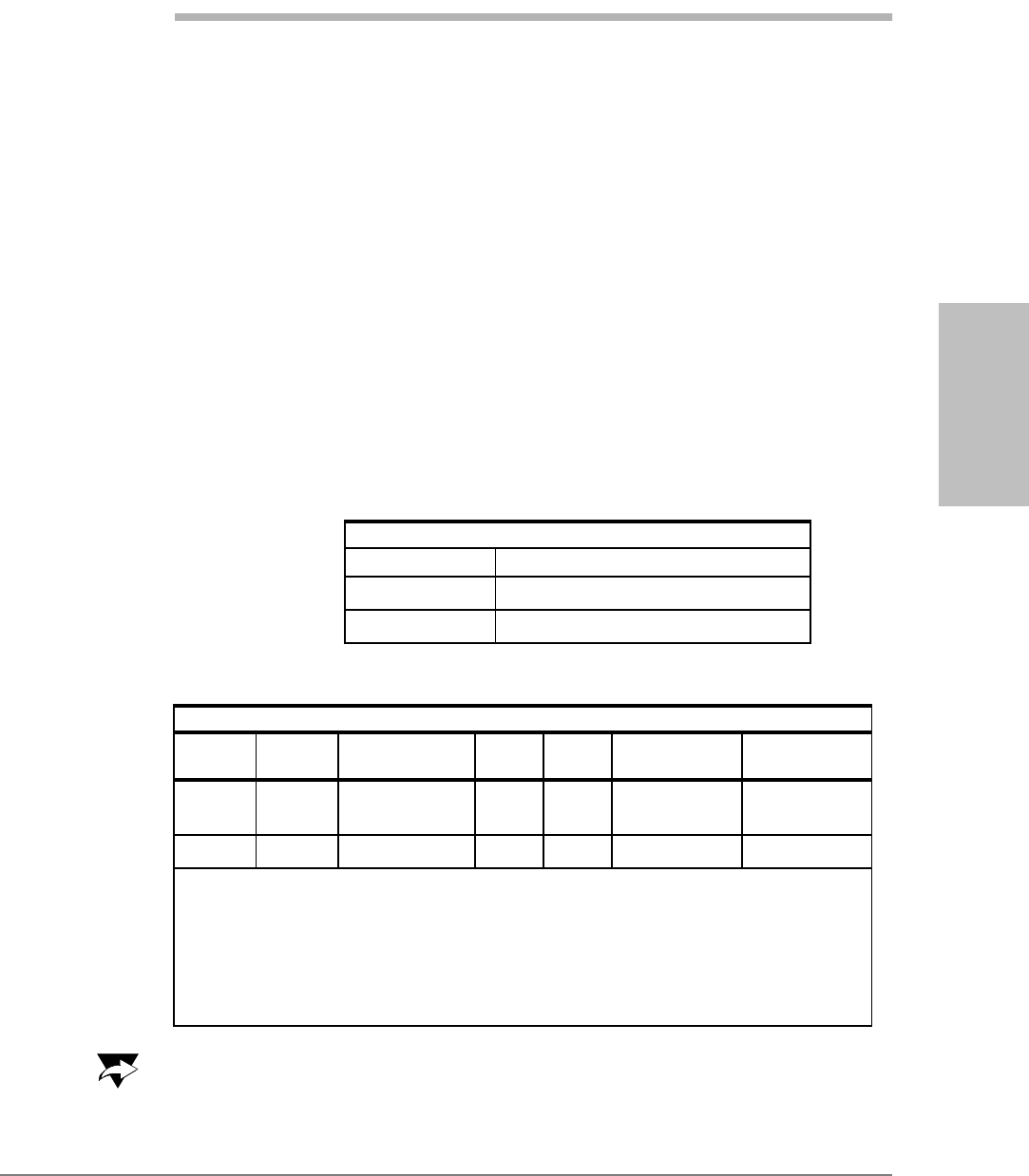
1. Swivel dipole
Manufacturer: Galtronics Inc.
Model number: 020806075-2397
Measured maximum gain (including RF cable loss): 2.2 dBi in cell band and
5.4 dBi in PCS band
Module Testing and
Integration
Kyocera Proprietary Kyocera 200 Module Data Book 59
UOJjUUSOJN=oÉîK=MMP jçÇìäÉ=qÉëíáåÖ=~åÇ=fåíÉÖê~íáçå
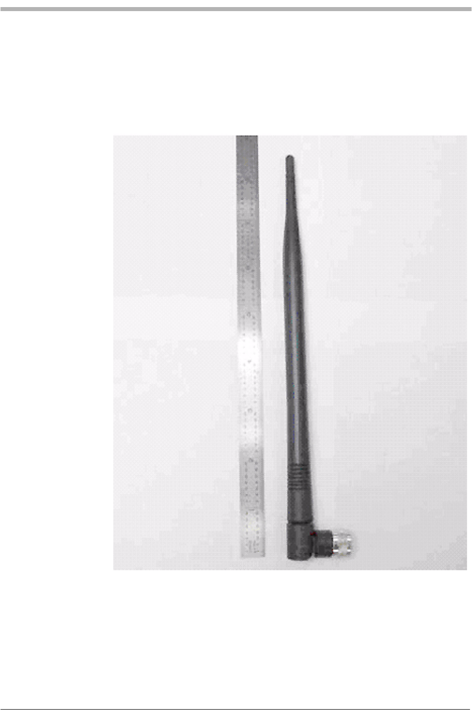
2. Mono pole dual band magnetic mount
Manufacturer: MAXRAD, Inc.
Model number: MDBM800/1900TNC
Rated gain: 2 dBi at 824-896 MHz, 2 dBi at 1850-1990 MHz
60 Kyocera 200 Module Data Book Kyocera Proprietary
jçÇìäÉ=qÉëíáåÖ=~åÇ=fåíÉÖê~íáçå UOJjUUSOJN=oÉîK=MMP
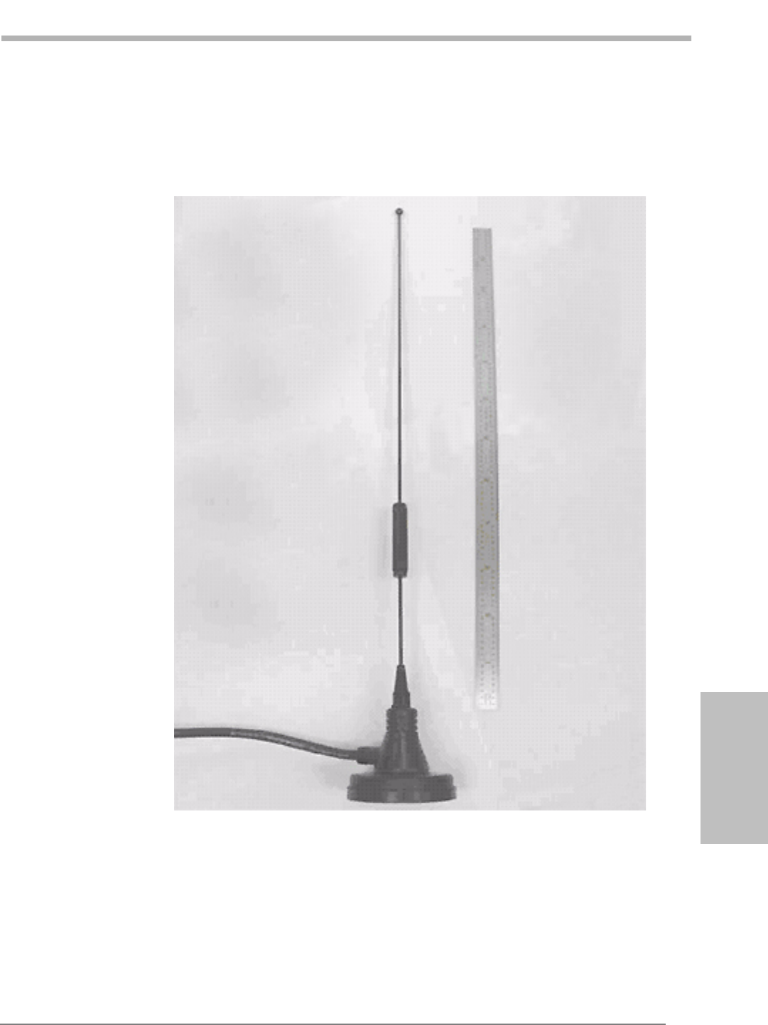
3. Mono pole and patch for GPS
Manufacturer: Mobile Mark, Inc.
Model number: SMV-UCE-1C2C
Rated gain: 2 dBi on Cellular, Unity on PCS

Module Testing and
Integration
Kyocera Proprietary Kyocera 200 Module Data Book 61
UOJjUUSOJN=oÉîK=MMP jçÇìäÉ=qÉëíáåÖ=~åÇ=fåíÉÖê~íáçå
4. Printed dipole
Manufacturer: Comverge Technologies, Inc.
Model number: UNIVERSAL MAINGATE C&I - CDMA ASSY 473609
Rated gain: Unity on Cellular, not designed for PCS
62 Kyocera 200 Module Data Book Kyocera Proprietary
jçÇìäÉ=qÉëíáåÖ=~åÇ=fåíÉÖê~íáçå UOJjUUSOJN=oÉîK=MMP
5. Quarter wave sleeve dipole for Cellular, half wave sleeve dipole for PCS
Manufacturer: Klong Electronics Co. Ltd.
Model number: EX-203
Rated gain: Cellular: 1.61 dBi, PCS: 2.77 dBi
Module Testing and
Integration
Kyocera Proprietary Kyocera 200 Module Data Book 63
UOJjUUSOJN=oÉîK=MMP jçÇìäÉ=qÉëíáåÖ=~åÇ=fåíÉÖê~íáçå
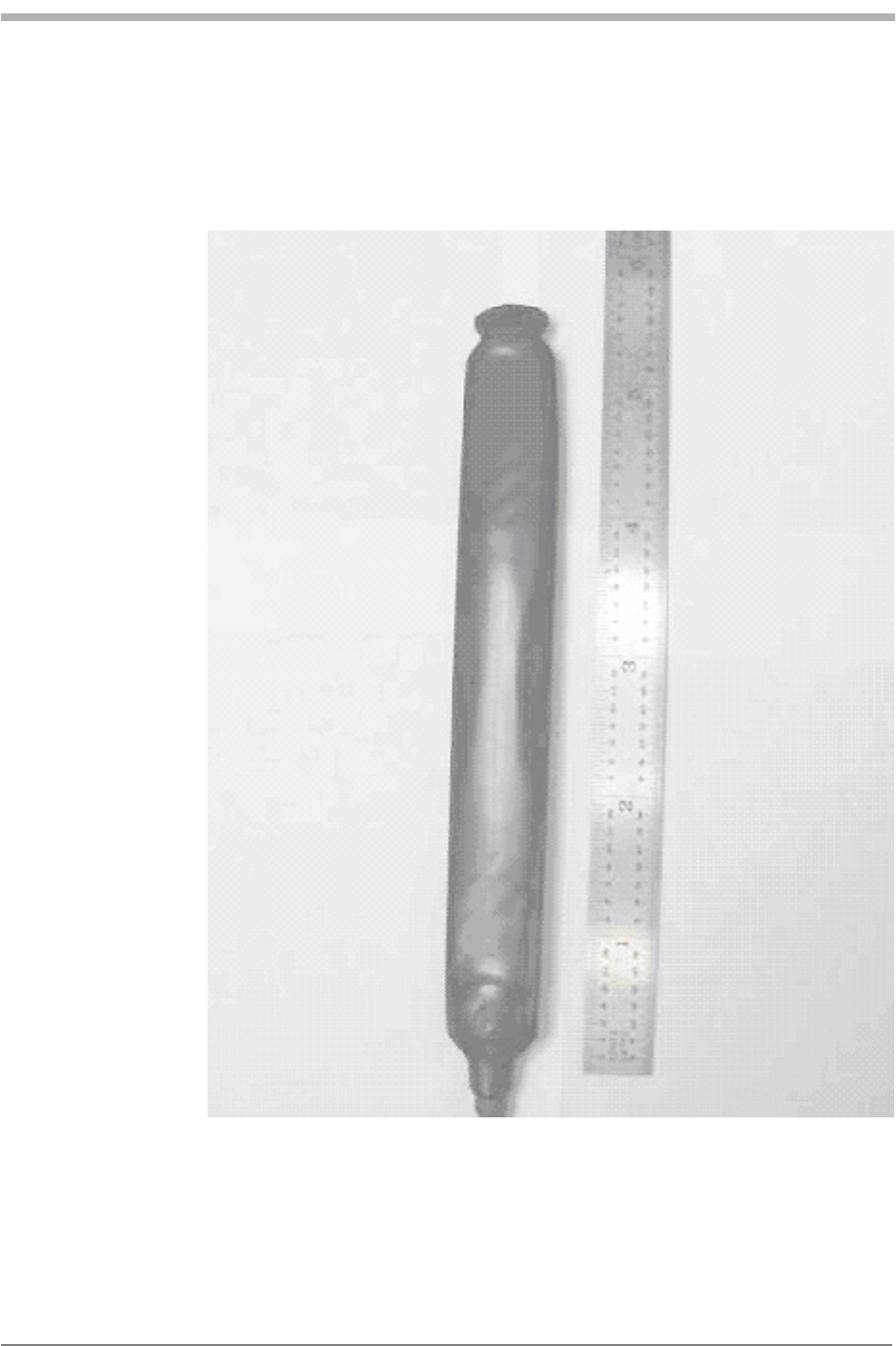
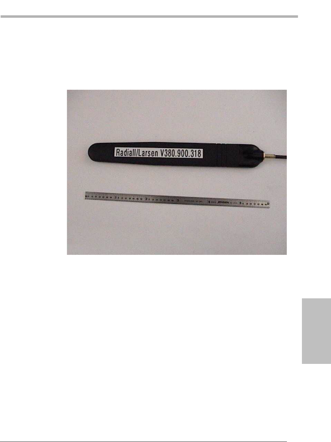
6. Dual Band AMPS/PCS Dipole Omnidirectional Antenna
Manufacturer: Radiall/Larsen Antenna Technologies
Model number: R380.900.318
Rated gain (including the cable losses): -1 dBi Max for 806-890 MHz,
-1 dBi Max for 1.85-1.99 GHz
64 Kyocera 200 Module Data Book Kyocera Proprietary
jçÇìäÉ=qÉëíáåÖ=~åÇ=fåíÉÖê~íáçå UOJjUUSOJN=oÉîK=MMP
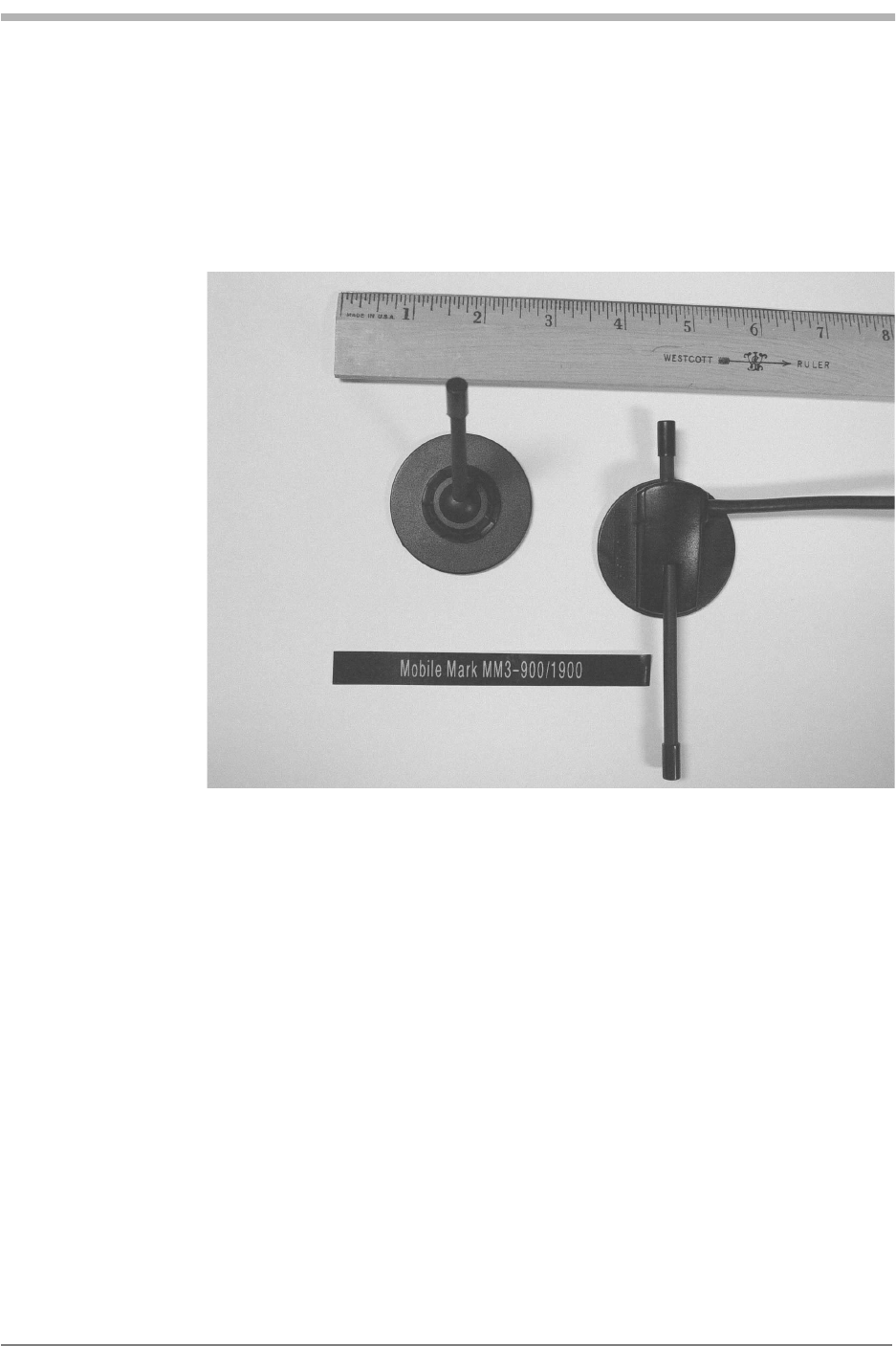
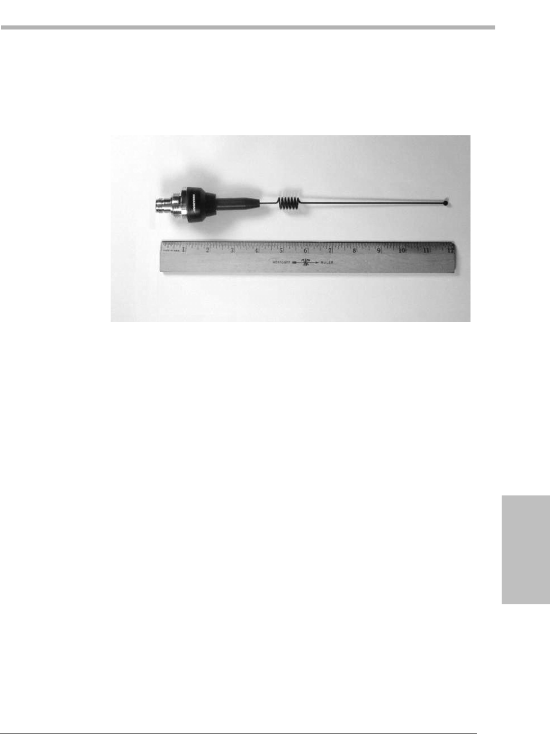
7. Dual Cellular/PCS On-Window whip
Manufacturer: Mobile Mark, Inc.
Model number: MM3-900/1900
Rated gain
Cellular Band: 3 dB maximum,
PCS: Unity Gain
Module Testing and
Integration
Kyocera Proprietary Kyocera 200 Module Data Book 65
UOJjUUSOJN=oÉîK=MMP jçÇìäÉ=qÉëíáåÖ=~åÇ=fåíÉÖê~íáçå
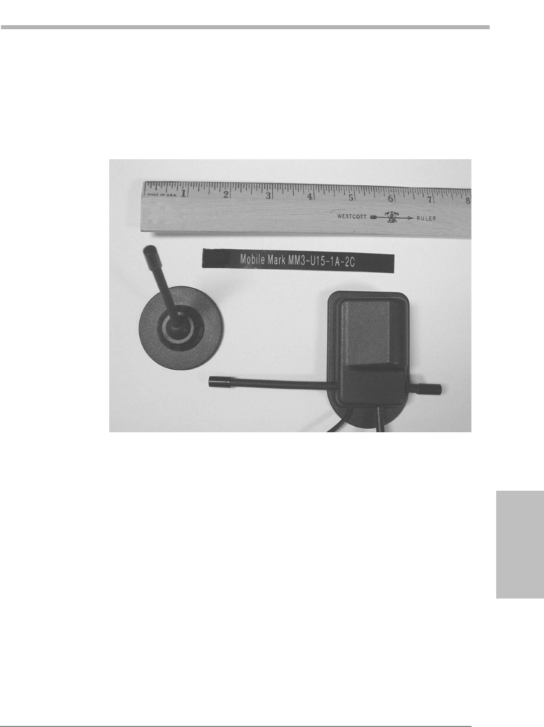
8. Surface Mount Quad Band for 800 - 2500 MHz & GPS
Manufacturer: Mobile Mark, Inc.
Model number: MM3-U15-1A-2C
Rated gain
800-GHz 2 dBi
1 GHz - 2.4 GHz Unity
66 Kyocera 200 Module Data Book Kyocera Proprietary
jçÇìäÉ=qÉëíáåÖ=~åÇ=fåíÉÖê~íáçå UOJjUUSOJN=oÉîK=MMP
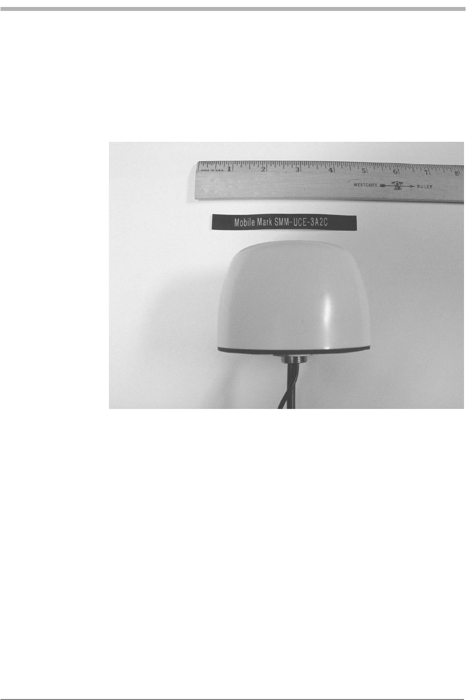
9. Glass Mount Tri-Band for Cellular, PCS & GPS
Manufacturer: Mobile Mark, Inc.
Model number: SMM-UCE-3A2C
Rated gain
Cellular Band: 3 dB maximum
PCS: Unity Gain
Module Testing and
Integration
Kyocera Proprietary Kyocera 200 Module Data Book 67
UOJjUUSOJN=oÉîK=MMP jçÇìäÉ=qÉëíáåÖ=~åÇ=fåíÉÖê~íáçå
10. Dual Band Collinear
Manufacture: MAXRAD, Inc.
Model Number: BMAX824/1850
Rated Gain: 2.2 dBi at 824-296 Mhz /4 dBi at 1850-1990 Mhz