L 3 Communications Avionics Systems TRC497 SkyWatch Traffic Advisory System User Manual COVER
L-3 Communications, Avionics Systems SkyWatch Traffic Advisory System COVER
Contents
- 1. Install Manual part 1 of 3
- 2. Install Manual part 2 of 3
- 3. Install Manual part 3 of 3
- 4. Pilots Guide part 1 of 2
- 5. Pilots guide part 2 of 2
Install Manual part 3 of 3

SKY497
Installation Manual
4-1
Rev. C
CHAPTER 4
MAINTENANCE
4.1 INTRODUCTION
This chapter contains general flight-line maintenance and troubleshooting procedures for installations
interfaced to WX-1000/SKY497 display or an alternate display. Removal of components is on condition of
failure. Troubleshooting is intended to aid in isolating failures to a defective assembly. Each time the TRC,
directional antenna, or directional antenna cables (including connectors) are replaced, the TRC must be
calibrated to the directional antenna (refer to paragraph 4.4.1).
4.2 CONTINUED AIRWORTHINESS
No scheduled maintenance is required to ensure continued airworthiness.
4.3 PERIODIC MAINTENANCE
At regular inspection intervals, do the periodic maintenance procedures of paragraph 4.3.1 thru 4.3.3.
4.3.1 WX-1000/SKY497 Display
1. Check that indicator cable is properly mated and secured.
2. Check to ensure unit is properly placed and secured to the instrument panel.
CAUTION
Do not use cleaning solvents on the viewing face.
3. Check face-plate for cleanliness. Wipe the viewing face with a damp lint-free, static-free cloth. If
necessary, clean with a soft cloth moistened with a mild solution of soap and water. Take care to
prevent cleaning solution from running down inside the case.
4.3.2 TRC
1. Check that connectors are properly mated and secure.
2. Check to ensure that the hold-down knobs on the mounting tray are secured to the TRC.
4.3.3 Antenna
1. Check for dents, cracks, and punctures.
CAUTION
Do not paint the antennas.
Do not use cleaning solvents on the antennas.
2. Remove all dirt and grease from surface areas. Clean with a soft cloth moistened with mild soap and
water.
3. Visually inspect sealant around the antenna base. Reapply sealant if required.
SKY497
Installation Manual
4-2
Rev. C
4.4 SERVICE MENU
The Service Menu is intended as an aid in installing, testing and troubleshooting the SKY497. Service
Menu items are to be used only for testing and troubleshooting an installation. The Service Menu is not
intended to be used by the pilot during normal system operation. When interfaced to an alternate display
the service menu functions must be performed by using an RS-232 terminal device, see appendix D for
operating instructions.
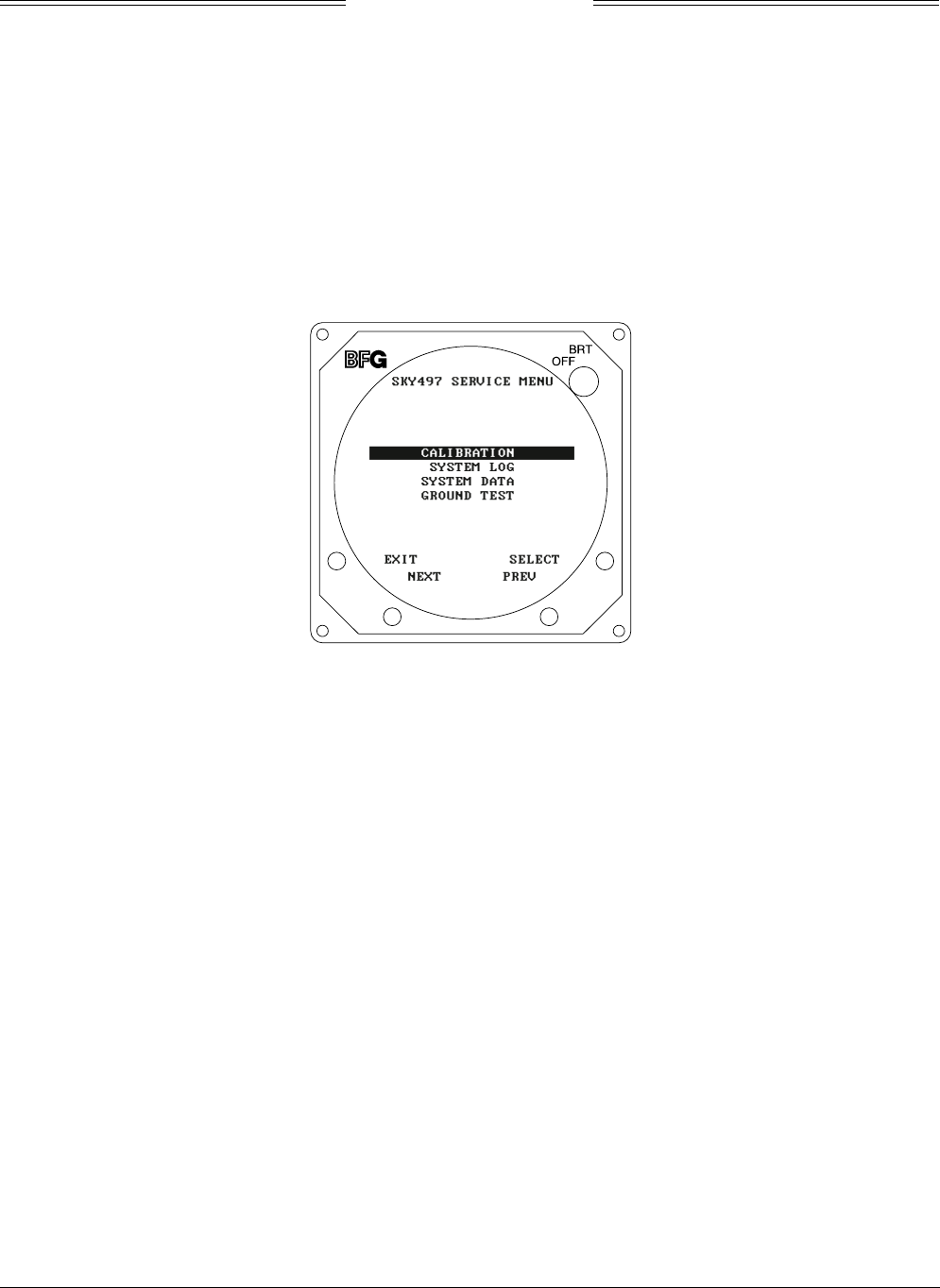
The Service Menu is accessed by holding soft-keys (1) and (2) (the left two buttons) depressed as the
system is turned on. Hold the buttons until the Service Menu is displayed. The Service Menu is shown in
figure 4-1.
Figure 4-1. Service Menu
The buttons perform the following operations:
• EXIT - causes the system to exit the Service Menu and run the power on self-test.
• SELECT - selects the highlighted item.
• PREV - steps to the previous item.
• NEXT - steps to the next item.
The Service Menu provides the following choices:
• Calibration
• System Log
• System Data
• Ground Test (Available only if squat switch input indicates aircraft is on the ground.)
The individual menu items are explained in the following paragraphs.
NOTE
Service Menu screens are shown for documentation purposes only. Each system
may be configured differently and live data will correspond to the sensors
installed in a particular aircraft..
SKY497
Installation Manual
4-3
Rev. C
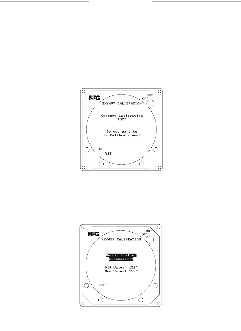
4.4.1 Calibration
NOTE
Ensure transponder is in standby while doing calibration.
Each time the TRC, directional antenna, or any of the directional antenna cables (including connectors)
have been repaired or replaced the TRC must be calibrated. Calibration is accessed by selecting that option
from the Service Menu (i.e., press SELECT with Calibration high-lighted). The initial calibration screen
(see figure 4-2) shows the current calibration value in degrees. Calibration can be performed with the
terminal device by using the Cal command.
NOTE
If the TRC has never been calibrated, the current calibration value will be displayed as 999.
Figure 4-2. Calibration Screen
Press YES to calibrate; press NO to return to the Service Menu. Soft-keys (3) and (4) are not used. During
the calibration procedure, the message “Re-Calibrating . . . ” will be displayed.
After a successful calibration, both old and new calibration values will be displayed (as shown in
figure 4-3). Press EXIT to return to the Service menu. Soft-keys (2), (3), and (4) are not used.
Figure 4-3. Successful Re-Calibration
SKY497
Installation Manual
4-4
Rev. C
The calibration value (000-359) is derived from a variety of measurements. Specific values are meaningless
however, in a failed TRC, a varying spread may indicate problems with the directional antenna system
(antenna, cables, or connectors) or the TRC.
If the calibration failed, the message “Re-calibration Failed!” will be display (see figure 4-4).
Figure 4-4. Failed Calibration
Press YES to calibrate; press NO to return to the Service Menu. Soft-keys (3) and (4) are not used.
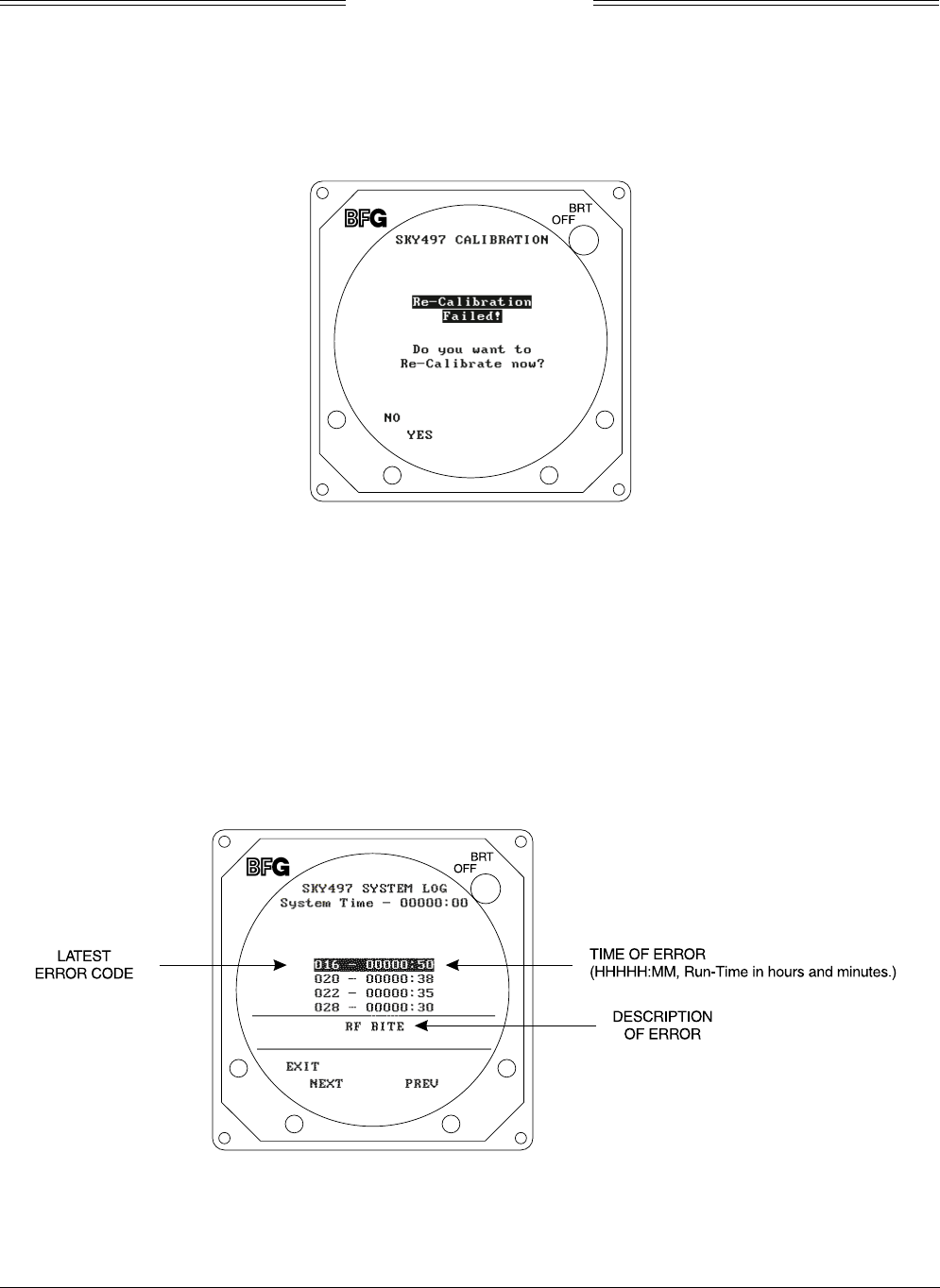
4.4.2 System Log
The 20 most recent errors detected by the system self-test are saved in the System Log. For each error, the
corresponding error code and run-time of occurrence are saved. The system log, as shown in figure 4-5, is
displayed by selecting that option from the Service Menu (i.e., press SELECT with System Log high-
lighted). System Log can be accessed with a terminal device by using the Dump command.
NOTE
Tables 4-2 and 4-3 provide a list and description of each error code (see paragraph 4.6).
Figure 4-5. System Log
SKY497
Installation Manual
4-5
Rev. C
The System Log displays the results in the following format:
### HHHHH:MM
where:
### = Error code.
HHHHH:MM = Run-time (in hours and minutes) at which error occurred.
The total elapsed run-time is displayed in the upper middle portion of the screen (System Time
HHHHH:MM).
A textual description of the highlighted error entry is displayed in the bottom portion of the screen.
If the System Log is empty, the following message is displayed:
NO FAULTS DETECTED
If, due to a failure of non-volatile memory, the System Log cannot be displayed, the following message is
displayed:
DATA NOT AVAILABLE
The buttons perform the following operations:
• EXIT - causes the system to return the Service Menu.
• NEXT - steps to the next entry.
• PREV - steps to the previous entry.
• Soft-key (4) is not used.
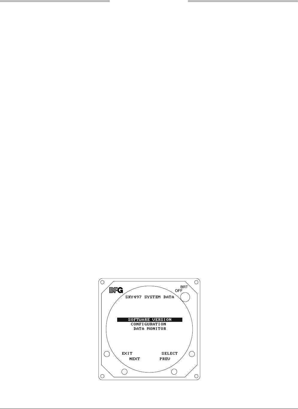
4.4.3 System Data
System Data screens (see figures 4-6 through 4-16) contain a record of setup information (software
identification and jumper configuration) and real-time sensor data. If you have problems with the SKY497,
verify the configuration screens match the wiring diagrams (see figures 2-2 and 2-3) and have this
information available when contacting BFGoodrich Avionics Systems Field Service Engineering. The field
service engineer must have adequate information to diagnose a problem. System Data screens are accessed
by selecting that option from the Service Menu (i.e., press SELECT with System Data high-lighted).
The System Data screen provides the following choices:
• Software Version
• Configuration
• Data Monitor
Figure 4-6. System Data
SKY497
Installation Manual
4-6
Rev. C
The buttons perform the following operations:
• EXIT - returns to the Service Menu (figure 4-1).
• SELECT - selects the highlighted item.
• PREV - steps to the previous item.
• NEXT - steps to the next item.
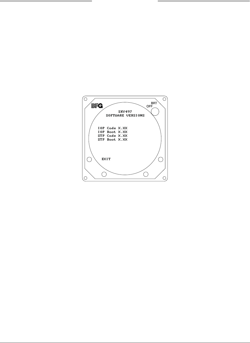
4.4.3.1 Software Version. The software version screen (see figure 4-7) identifies:
• IOP Code Version
• IOP Boot Version
• STP Code Version
• STP Boot Version
Software version can be accessed with a terminal device by using the Version command.
Figure 4-7. Software Version
NOTE
The software version identified on the TRC equipment tag represents the system software
configuration (i.e., a collective designator for all software/firmware installed within the
unit).
Press EXIT to return to the System Data screen. Soft-keys (2), (3) and (4) are not used.
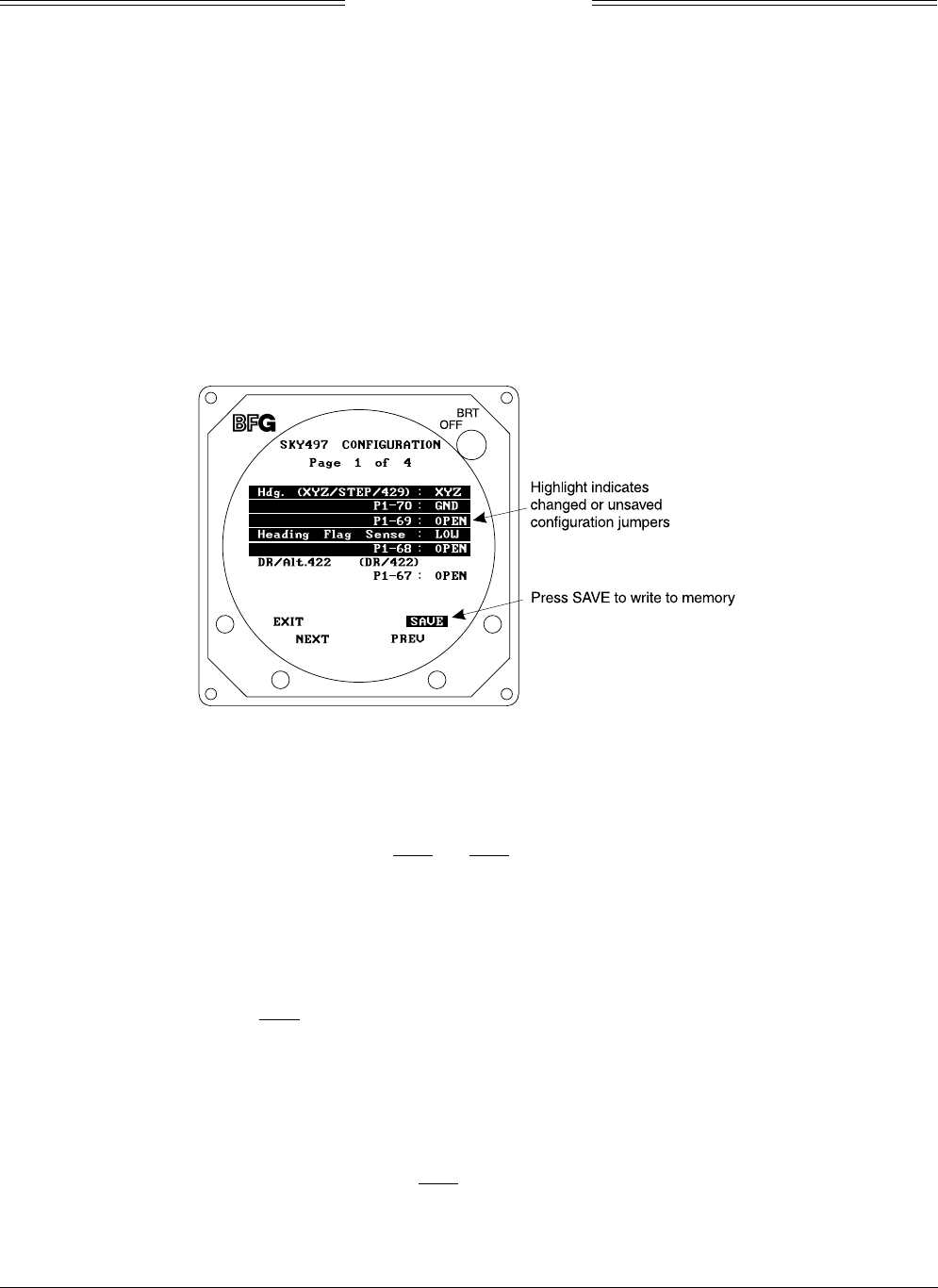
4.4.3.2 Configuration. The configuration display consists of 4 pages. Configuration data on pages 1, 3 and 4
must be verified and saved on all new installations or if changes in configuration jumper(s) occur. The
buttons perform the following operations:
• EXIT - returns to the System Data Menu (figure 4-6).
• NEXT - steps to the next page.
• PREV - steps to the previous page.
• SAVE - saves configuration data for that page (not present if configuration jumpers
match configuration memory).
Configuration information can also be accessed with a terminal device by using the Config command.
SKY497
Installation Manual
4-7
Rev. C
NOTES
1. Saved configuration data is read at power-up and compared with
configuration jumpers. If the saved configuration data has never been
saved (e.g., new installations) an ERROR 30 Check Configuration will
occur when the box comes out of standby. If the saved configuration data
does not match the current jumper(s) an error 30 will occur at power-up.
The conflicting jumper(s) will be highlighted on configuration screen(s).
(See figure 4-8.)
2. Configuration pages 1, 3 and 4 contain configuration jumper data. On
each page verify jumpers are correct and press SAVE to write the new
configuration into system memory. When done the SAVE button
disappears. Repeat this step for each page. Save command can be used if
using a terminal device.
Figure 4-8. Configuration - Page 1
Page 1 of 4 (see figure 4-8) displays:
• Heading Input Source (Hdg.: XYZ, STEP, 429, or NONE)
Configuration Jumpers P1-69 & P1-70 (OPEN or GND)
P1-69 P1-70
None OPEN OPEN
Synchro XYZ OPEN GND
Stepper GND OPEN
ARINC 429 Bus GND GND
• Heading Flag Sense (HIGH or LOW)
Configuration Jumper P1-68 (OPEN or GND)
P1-68
OPEN If LOW level input on HDG_FLG+ (P1-53) indicates
valid heading or no valid heading input is available.
GND If HIGH level input on HDG_FLG+ (P1-53) indicates
valid heading.
• RS422 Interface (DR/Alt. 422: DR or 422)
Configuration Jumper P1-67 (OPEN or GND)
P1-67
Data Recorder OPEN
Alternate* GND
*Future Option
SKY497
Installation Manual
4-8
Rev. C
NOTE
The RS422 Interface is used for factory testing and evaluation.
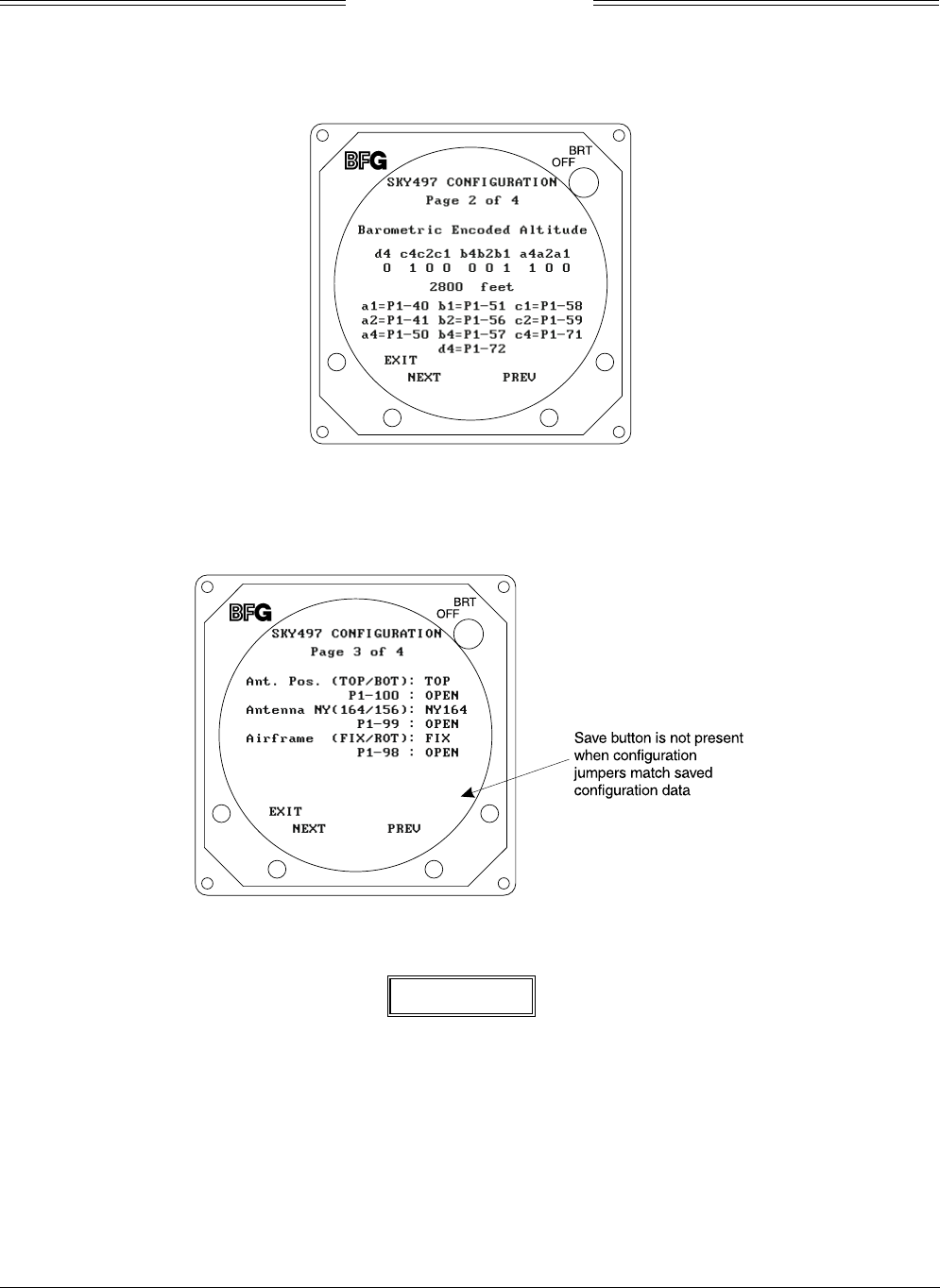
Figure 4-9. Configuration - Page 2
Page 2 of 4 (see figure 4-9) displays:
• Barometric Encoded Altitude (in Gray Code and Feet)
• Connector P1 Pin Assignments for Data Inputs
Figure 4-10. Configuration - Page 3
WARNING
Verify displayed antenna position matches antenna location on the aircraft
(top or bottom). Failure to do so could give incorrect traffic bearing.
SKY497
Installation Manual
4-9
Rev. C
Page 3 of 4 (see figure 4-10) displays:
• Antenna Position (Ant. Pos.: TOP or BOT)
Configuration Jumper P1-100 (OPEN or GND)
P1-100
Top OPEN
Bottom* GND
*See paragraph 2.3 (ANTENNA LOCATION)
• Antenna Type (NY164 or NY156)
Configuration Jumper P1-99 (OPEN or GND)
P1-99
NY164 OPEN
NY156 GND
• Airframe (Ant. Pos.: FIX or ROT)
Configuration Jumper P1-98 (OPEN or GND)
P1-98
Fixed Wing OPEN
Rotorcraft GND
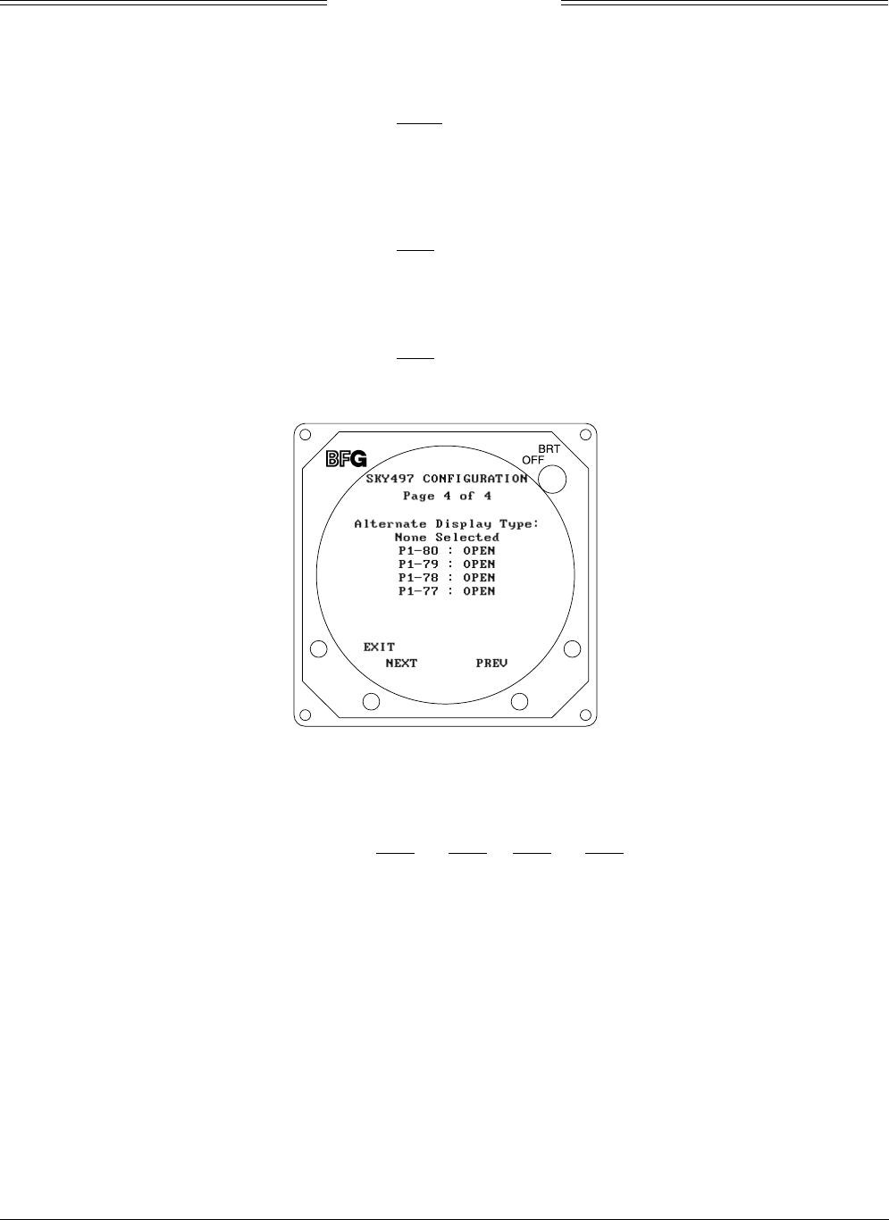
Figure 4-11. Configuration - Page 4
Page 4 of 4 (see figure 4-11) displays:
• Alternate Display Type (None Selected, ARINC 735 Type 1, or Illegal Display)
Configuration Jumpers P1-77, P1-78, P1-79 & P1-80 (OPEN or GND)
P1-77 P1-78 P1-79 P1-80
None OPEN OPEN OPEN OPEN
735 Type 1 OPEN OPEN OPEN GND
4.4.3.3 Data Monitor. The data monitor display consists of 5 pages. The buttons perform the following
operations:
• EXIT - returns to the System Data Menu (figure 4-6).
• NEXT - steps to the next page.
• PREV - steps to the previous page.
• Soft-key (4) is not used.
The data monitor information can be accessed with a terminal device by using the Bar, Head, Rad and
Config commands.
SKY497
Installation Manual
4-10
Rev. C
Figure 4-12. Data Monitor - Page 1
NOTE
Values displayed on the Data Monitor are continuously updated. The sensor
source (e.g., ARINC 429, Synchro XYZ, etc.) is latched at power-up. If it is
necessary to change a configuration, cycle power to ensure the correct
information is read into memory.
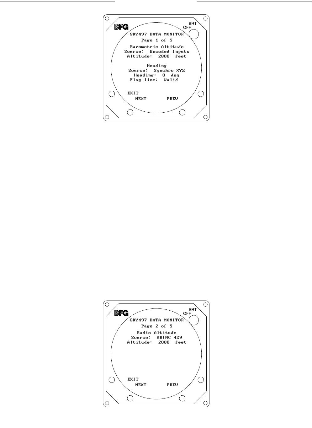
Page 1 of 5 (see figure 4-12) displays:
• Barometric Altitude
Source (Encoded Inputs, ARINC 429, or Simulated)
Altitude (in Feet)
• Heading Data
Source (Synchro XYZ, ARINC 429, None, or Simulated)
Heading (in Degrees)
Flag Line (Valid or Invalid)
NOTES
1. When the system is set to GROUND TEST, the barometric altimeter is
simulated to 50,000 ft and the heading simulated to 0 degrees.
2. If an INVALID “Flag Line” is detected, the “Heading” will be flagged
INVALID.
Figure 4-13. Data Monitor - Page 2
SKY497
Installation Manual
4-11
Rev. C
Page 2 of 5 (see figure 4-13) displays:
• Radio Altitude
Source (ARINC 429, None, or Simulated)
Altitude (in Feet)
NOTE
When the system is set to GROUND TEST, the radio altimeter simulated to 2,500 ft.
Figure 4-14. Data Monitor - Page 3
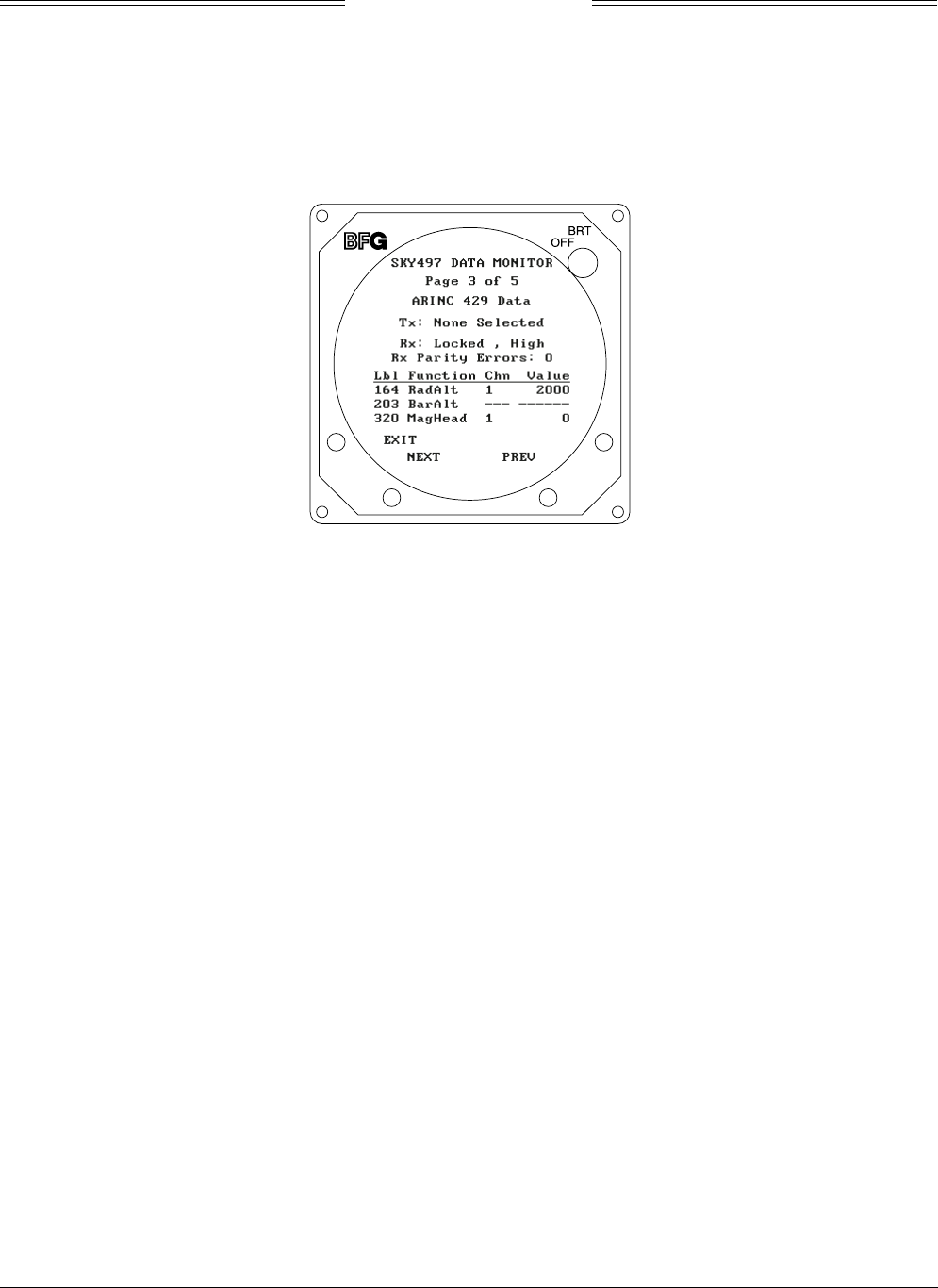
Page 3 of 5 (see figure 4-14) displays ARINC 429 Data:
• Transmit Data (Tx: None Selected or ARINC 735 Type 1*, Illegal)
*Alternate Display Device
• Received Data (Rx):
Status (Locked or Seeking)
Speed (High or Low)
Number of Parity Errors
• Label Data
Label Number & Function
164 RadAlt (Radar Altimeter)
203 BarAlt (Barometric Altimeter)
320 MagHead (Magnetic Heading)
Channel (1 or 2)
Value (Altitude in Feet; Heading in Degrees)
A “Failed” message will appear if the system fails an internal ARINC 429 communications test.
SKY497
Installation Manual
4-12
Rev. C
Figure 4-15. Data Monitor - Page 4
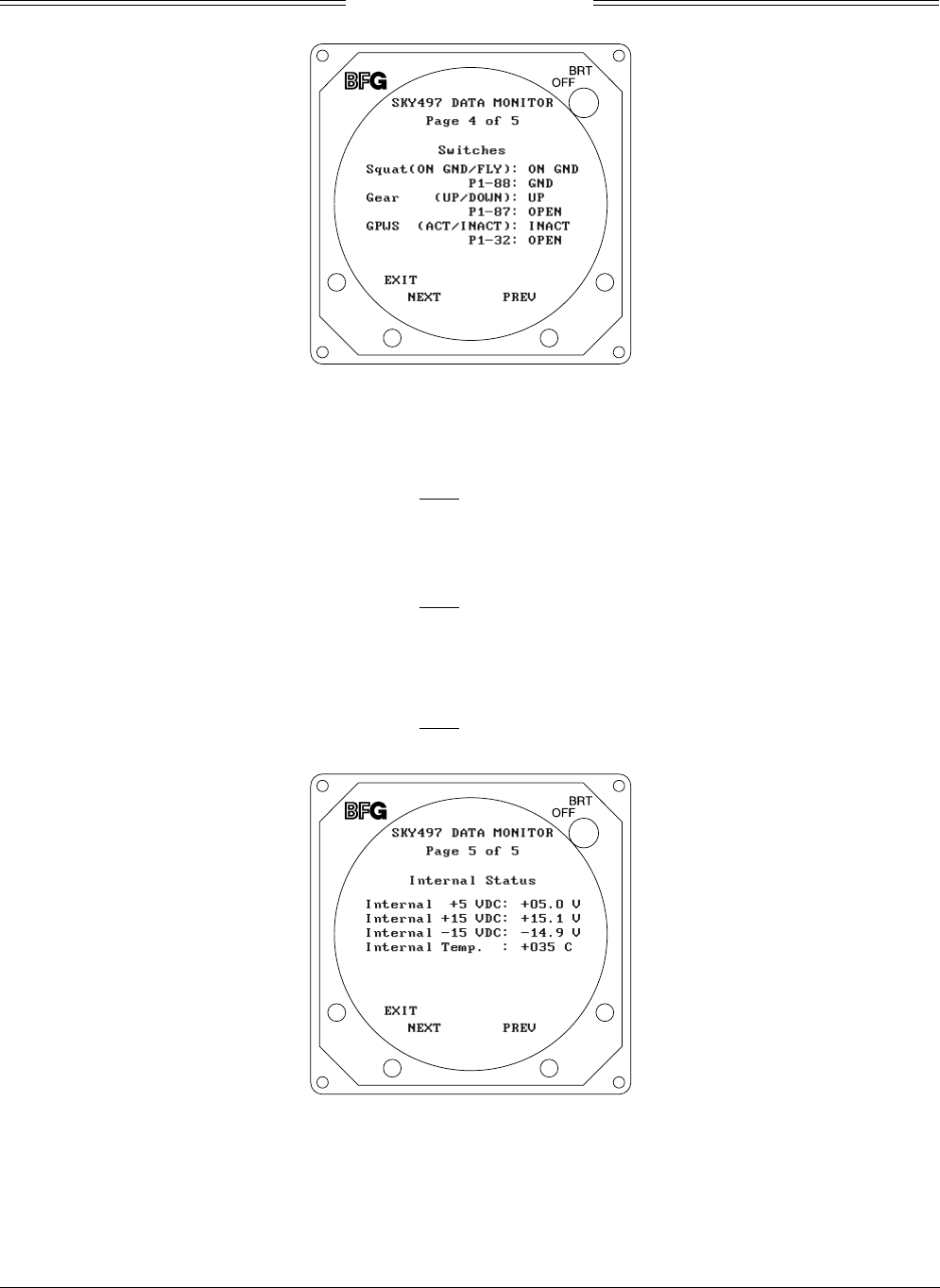
Page 4 of 5 (see figure 4-15) displays switch status:
• Squat Switch (ON GND/FLYING)
Connector P1-88 (SQUAT) Input (OPEN or GND)
P1-88
Flying OPEN
On Ground GND
• Landing Gear (UP/DOWN)
Connector P1-87 (GEAR) Input (OPEN or GND)
P1-87
Gear Up OPEN
Gear Down GND
• GPWS (ACTIVE/INACTIVE)
Connector P1-33 (GPWS) Input (OPEN or GND)
P1-32
Inactive OPEN
Active GND
Figure 4-16. Data Monitor - Page 5
Page 5 of 5 (see figure 4-16) displays measurements of the following internal values:
• Voltage (+5 VDC, + 15 VDC, & -15 VDC)
• Processor Temperature (Degrees C)
SKY497
Installation Manual
4-13
Rev. C
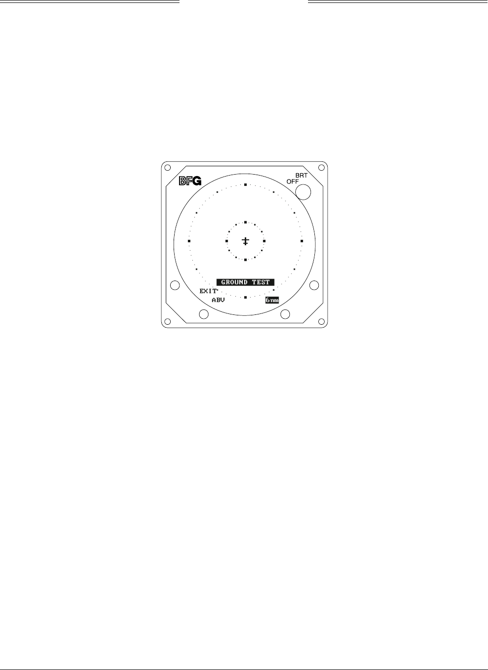
4.4.4. Ground Test
Ground Test initializes the system for on-the-ground testing. In this configuration, the barometric
altimeter is simulated to 50,000 ft, heading simulated to 0 degrees, and the radar altimeter simulated to
2,500 ft.
NOTE
Ground test is available only if the squat switch input indicates aircraft is on the ground.
Ground test (see figure 4-17) is accessed by selecting that option from the Service Menu (i.e., press
SELECT with Ground Test highlighted). To access ground test with a terminal device use the Ground
Test command.
Figure 4-17. Ground Test
If the system detects a heading fault, HDG will be displayed in the bottom center portion of the screen.
The buttons perform the following operations in this mode:
• EXIT - causes the system to return the System Data Menu (figure 4-6).
• Soft-key (2) toggles the system through the above (ABV), normal (NRM), and below (BLW)
altitude display modes. It is labeled to indicate current mode (i.e., ABV, NRM, or BLW).
• Soft-key (3) toggles the display range between 2 and 6 nm. It is labeled to indicate current
range (i.e., 2nm or 6nm).
• Soft-key (4) is not used.

SKY497
Installation Manual
4-14
Rev. C
4.5 TROUBLESHOOTING
Table 4-1 is intended to assist trained electronic technicians to determine which assembly is inoperative.
Do the corrective action steps in the order described. Use the Service Menu (refer to paragraph 4.4) as an
aid in fault isolation. Information available from the service menu can help identify conditions that need to
be resolved. If interfaced to an alternate display service menu must be accessed via an RS-232 terminal
device, see Appendix D for operating instructions.
Table 4-1. Fault Isolation
SYMPTOM CORRECTIVE ACTION
Display remains dark after SKYWATCH is powered ON. a. Check position of the WX-1000 maintenance switch
(NORMAL/OVERRIDE).
b. Reset circuit breaker if it is tripped.
c. Check aircraft power source.
d. Check connection to WX-1000 processor, if installed.
e. Check power input at TRC mating connector.
P8-A +28V (10.5-34V PWR)
P8-B +28V_RET (AIRCRAFT PWR RETURN)
f. Check cables connected to display.
g. Replace Display.
Display is distorted. Check for interference from aircraft systems.
Incorrect response to buttons (soft-keys). Check soft-key wiring inside display cable and WX-1000
processor cable (if installed).
SKYWATCH will not enter service menu. a. Check soft-key wiring.
b. Verify alternate display pins (P1-77, P1-78, P1-79, or
P1-80) are not configured to ground. Service menu is
not accessible via softkeys when an alternate display is
configured.
c. If using an alternate display service menu must be
accessed via an RS-232 terminal device.
The self-test successfully completes without audio
annunciation.
a. Check headphones/speaker and aircraft audio panel
switch settings.
b. Check cables connected to TRC.
Audio Alert Output:
P1-92 (AUDIO_H - 600-Ohm)
P1-91 (AUDIO_L - 150-Ohm)
P1-90 (AUDIO_C - Common)
SKYWATCH Failed. a. Check system log (para 4.4.2) for errors. Error
messages are detailed in para 4.6.
b. Replace TRC.
Self-test does not execute. Aircraft is on the ground. a. If standby screen is displayed, check soft-key wiring
inside display cable and WX-1000 processor cable
(if installed).
b. Check connection between the TRC and the squat
switch sensor.
Squat Switch Input: P1-88
The display cannot be switched between SKYWATCH and
the WX-1000. Both systems are installed.
a. Check circuit breakers. Reset if tripped.
b. Check position of the WX-1000 maintenance switch
(SW2). It should be set to the NORMAL position.
c. Check wiring of the SKYWATCH/
Stormscope
display
mode switch (para 2.6.11/figure 2-2).
WX-1000 processor has been removed for service;
SKYWATCH fails to operate.
Check position of the WX-1000 maintenance switch
(NORMAL/OVERRIDE). When the WX-1000 has been
removed for service, it should be set to the OVERRIDE
position. This switch may be located in the avionics bay.

SKY497
Installation Manual
4-15
Rev. C
Table 4-1. Fault Isolation (Continued)
SYMPTOM CORRECTIVE ACTION
SKYWATCH paints itself as a target (e.g., TA). a. Verify suppression bus shielded cable is grounded
correctly at both ends.
b. Connect an oscilloscope to the suppression bus and
verify that the SKY497 suppression pulse (100 µs ±5 µs)
exceeds +15 V dc.
c. If less than +15 V dc, the suppression bus is
overloaded.
d. Check all equipment connected to the bus.
e. Repair/replace the offending device.
SKYWATCH TRC497 has been removed for service; the
WX-1000
Stormscope
fails to operate.
Check the adapter plug (see para 4.7). If the TRC497 is
removed for service, an adapter plug is required to permit
continued operation of the WX-1000.
4.6 ERROR MESSAGES
SKYWATCH firmware is designed to generate error messages associated with a particular condition or
step in the program. The 20 most recent errors detected by the system are saved in the System Log (see
para 4.4.2). System Log can be accessed with a terminal device by using the Dump command. For your
convenience, in table 4-2, we have listed the error messages that have been associated with SKYWATCH
installations. Where appropriate, procedures that may assist in resolving installation problems are
provided. When a severe error occurs SKYWATCH will fail.
Table 4-2. Installation Related Error Messages
ERROR NO. MESSAGE Remarks
ERROR 016 RF BITE a. Check directional antenna and associated cables.
b. Turn system power ON.
c. Calibrate directional antenna (para 4.4.1).
NOTE
Ensure transponder is in standby and DME is OFF while doing calibration.
d. Cycle power.
e. Run pilot initiated self-test.
ERROR 017 RF Amplitude a. Check directional antenna and associated cables.
b. Turn system power ON.
c. Calibrate directional antenna (para 4.4.1).
NOTE
Ensure transponder is in standby and DME is OFF while doing calibration.
d. Cycle power.
e. Run pilot initiated self-test.
ERROR 18 RF Angle a. Check directional antenna and associated cables.
b. Turn system power ON.
c. Calibrate directional antenna (para 4.4.1).
NOTE
Ensure transponder is in standby and DME is OFF while doing calibration.
d. Cycle power.
e. Run pilot initiated self-test.

SKY497
Installation Manual
4-16
Rev. C
Table 4-2. Installation Related Error Messages (Continued)
ERROR NO. MESSAGE Remarks
ERROR 020 Barometric Altitude Input a. Check altimeter source. Is the unit turned on and been given enough
time to warm up.
NOTE
When interfacing via an ARINC 429 serial data bus, at power-up
the TRC must adjust (auto-baud) to the speed of the incoming
data. Normally the TRC will lock-on after approximately 15
seconds.
b. Cycle power.
c. Ensure that barometric altitude is input from only one
source (Gray Code or ARINC 429, not both).
d. Encoded inputs can be checked from the system configuration screen
(para 4.4.3.2, Configuration - Page 2).
e. Using the Data Monitor, verify barometric source and altitude
(para 4.4.3.3).
f. Check wiring associated with altimeter source.
ERROR 021 Power Supply a. Using the Data Monitor, observe internal voltage measurements
(para 4.4.3.3, Data Monitor - Page 5).
b. Check aircraft power source.
c. Check power input at mating connector.
P8-A +28V (10.5-34V PWR)
P8-B +28V_RET (AIRCRAFT PWR RETURN)
ERROR 30 Check Configuration Configuration jumpers not saved or changed and need validated.
a. Using the Configuration menu, verify pages 1, 3 and 4 are correct
then save (para 4.4.3.2, Configuration).
b. Check wiring associated with configuration jumpers.
ERROR 152 HDG Invalid synchro XYZ input.
a. Check heading source.
b. Verify status of heading configuration jumpers (input source and flag
sense - para 4.4.3.2).
c. Using the Data Monitor, verify heading data (source, heading
& flag - para 4.4.3.3).
d. If the heading signals become valid, the system will recover
automatically.
e. Check wiring associated with compass heading.
ERROR 153 HDG Invalid heading reference (400 Hz).
a. Check heading source.
b. Verify status of heading configuration jumpers (input source and flag
sense - para 4.4.3.2).
c. Using the Data Monitor, verify heading data (source, heading
& flag - para 4.4.3.3).
d. If the reference signal becomes valid, the system will recover
automatically.
e. Check wiring associated with compass heading.

SKY497
Installation Manual
4-17
Rev. C
The error messages in table 4-3 are used by factory technicians in determining what actions may have
preceded a system failure. These messages do not necessarily indicate a current system failure and are
provided for information only. Should the installer observe these messages in the error log without a
SKY497 Failed message during normal operation, no service action is required.
Table 4-3. Informational Error Messages
ERROR NO. MESSAGE ERROR NO. MESSAGE
ERROR 001 Boot ERROR 146 Processor
ERROR 019 RF Transmitter ERROR 147 Processor VGA Memory
ERROR 022 Processor RAM ERROR 148 Processor RAM (Low Byte)
ERROR 023 Processor ROM ERROR 149 Processor RAM (High Byte)
ERROR 024 Processor Reset ERROR 150 Flash Memory Checksum
ERROR 025 RF Self Test Timeout ERROR 151 HDG
ERROR 026 Processor Not Detected ERROR 154 Processor Timeout
ERROR 027 Self Test Comm ERROR 155 Operating System
ERROR 028 Pulse Detection HW ERROR 156 HDG
ERROR 029 Processor Comm ERROR 157 Processor Fault
ERROR 129 Boot ERROR 158 ARINC 429
ERROR 144-145 Processor Comm
SKY497
Installation Manual
4-18
Rev. C
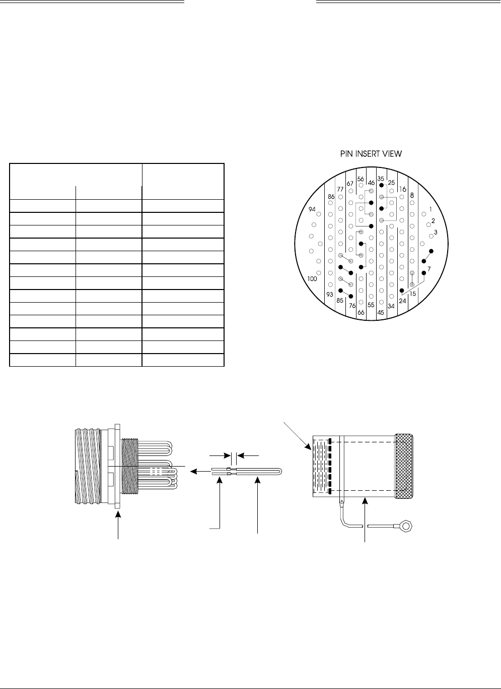
4.7 TRC497/WX-1000 ADAPTER PLUG
An adapter plug can be used to by-pass SKYWATCH if a WX-1000 Stormscope system is installed. The
adapter will permit continued operation of the WX-1000 if the TRC497 is removed for service. It can also
be used as a troubleshooting tool when attempting to isolate a problem to either or both systems.
The adapter plug mates with P1. It can be purchased from BFGoodrich Avionics Systems (P/N 805-10810-
001) or fabricated locally from the details provided in table 4-4 and figures 4-18 and 4-19.
Table 4-4. Adapter Plug Jumpers
JUMPER PINS
FUNCTION
56DPWR-15
724DPWR+15
14 15 DSPLY_GND
35 37 VIDEO_LO
36 38 VIDEO_HI
46 48 HSYNC_LO
47 49 HSYNC_HI
60 62 VSYNC_LO
61 63 VSYNC_HI
73 82 SFTKEY4
74 83 SFTKEY3
75 84 SFTKEY2
76 85 SFTKEY1
Figure 4-18. Adapter Plug Jumper Installation
CONNECTOR
MIL # D38999/20FH35PN
CRIMP PIN
JUMPER
#22 AWG WIRE SHORTING CAP
BACKSHELL
GLENAIR #340HS002M23-2H12A
0.10
+0.07
-0.00
NOTE
APPLY LOCTITE TO THE INTERNAL THREADS
OF THE BACKSHELL PRIOR TO ASSEMBLY.
®
Figure 4-19. Adapter Plug Assembly

SKY497
Installation Manual
4-19
Rev. C
4.8 DISPOSITION OF FAILED ITEMS
Return defective components to your authorized BFG Avionics Systems dealer or to::
BFG Avionics Systems
Attn: Customer Service
5353 52nd Street, S.E.
Grand Rapids, MI USA 49588-0873
If available, pack components in their original shipping container. If the original container is not available,
pack them as follows:
CAUTION
Do not use desiccant crystals when packaging electronic assemblies. Since the
assembly must be packed tightly, crystals in bag form cannot be used. The use of
loose crystals may cause unnecessary damage resulting in a cleaning problem.
1. Ensure that nonconductive covers/caps are installed on the exposed terminals of cable connectors on
the display, TRC, and antenna.
2. The display and TRC contain electrostatic discharge sensitive (ESDS) parts and must be wrapped in
static protective materials.
3. Wrap with bubble pack. Secure bubble pack with reinforced tape.
4. Place assembly in a cardboard box.
5. Wrap any accessories in tissue and place in the box. Fill spaces with bubble pack.
6. Put a letter on top of bubble pack. The letter must contain:
•Your name, address, and telephone number.
•Purchase order number.
•Description of component including, when applicable, model and serial number.
•Date of purchase.
•A brief description of the difficulty.
• Type of display and radar altimeter.
• Copy of error log, if available.
7. Shut box and seal with reinforced tape.
8. Attach packing list to outside of box.

SKY497
Installation Manual
4-20
Rev. C
This page intentionally left blank.

SKY497
Installation Manual
A-1
Rev. C
APPENDIX A
SKY497 INTERFACE
SIGNAL & CABLE CHARACTERISTICS
A.1 INTRODUCTION
This appendix defines the electrical characteristics of all input and output signals to the SKY497 System.
Sufficient data is included to perform an electrical load analysis for the aircraft. The interface
characteristics contained in this appendix are fully compatible with ARINC specifications where noted.
Connection information identifies the connector-pin and signal names as they appear on the interconnect
wiring diagram(figures 2-2 and 2-3) or, in the case of antenna cables, the connector type (e.g., BNC or
TNC).
NOTE
External isolation diodes are not required and SHOULD NOT be installed.
SIGNAL CHARACTERISTICS
Altitude Digitizer / These signals are Gilham Code (or Gray Code) inputs coming from an
Encoding Altimeter Input airdata computer or altitude digitizer (see para 2.6.6). These 10 lines may
be connected in parallel with the aircraft transponder. If the aircraft is
equipped with selectable altitude encoders, connect the altitude inputs so
that SKY497 is always connected to the selected encoder. (Reference
ARINC 572-1.)
NOTE
Only one altimeter input source (Gray Code or ARINC 429, not both)
should be connected. The altimeter input should be from the same source
that is interfaced with the transponder or at least as accurate as that
source, i.e., ± 125 ft.
CONNECTION TRC P1-40 (ALT_A1)
TRC P1-41 (ALT_A2)
TRC P1-50 (ALT_A4)
TRC P1-51 (ALT_B1)
TRC P1-56 (ALT_B2)
TRC P1-57 (ALT_B4)
TRC P1-58 (ALT_C1)
TRC P1-59 (ALT_C2)
TRC P1-71(ALT_C4)
TRC P1-72 (ALT_D4)
TRC P1-81 (ALT_COMN)
CABLE Minimum 22 AWG wire for each connection
for lengths up to 30 ft.
VOLTAGE +30 V input max.
CURRENT <1 mA sourced per line.
FREQUENCY <100 Hz
SOURCE Z >10 kΩ per line.
MAX CAPACITANCE <20 pF per line.
NOTE
If the aircraft has switched encoders that use 28V RETURN or AIRCRAFT
GROUND as reference for encoder selection, then ALT_COMMON (TRC
P1-81) should be left unconnected.

SKY497
Installation Manual
A-2
Rev. C
SIGNAL CHARACTERISTICS
Antenna Top Directional SUM (SIGMA) Port (Blue)
CONNECTION TRC J9, TNC connector.
CABLE Cable attenuation must not exceed 2.5 dB, VSWR
1.5:1. Refer to para 2.6.1.
Impedance: 50 Ω
Antenna Top Directional BIT PROBE Port (Black)
CONNECTION TRC J10, BNC connector.
CABLE Cable attenuation must not exceed 6 dB, VSWR
1.5:1. Refer to para 2.6.1.
Impedance: 50 Ω
Antenna Top Directional DIFFERENCE (DELTA) Port (Red)
CONNECTION TRC J11, TNC connector.
CABLE Cable attenuation must not exceed 2.5 dB, VSWR
1.5:1. Refer to para 2.6.1.
Impedance: 50 Ω
ARINC 429 External Interface The SKY497 has two ARINC 429 receivers and one transmitter (see para
2.6.5). The receivers operate at either low speed (12.5 kHz) or high speed
(100 kHz). The transmitter operates only at high speed (100 kHz).
The ARINC 429 transmitter is intended to provide the capability to
interface with alternate display devices other than the WX-1000/SKY497
display.
The two ARINC 429 receivers can be used to input data from other
avionics systems. The following labels are supported:
LABEL FUNCTION
164 Radio Altimeter (See note 1 & 3.)
203 Barometric Altitude (Uncorrected - see note 3.)
320 Magnetic Heading (See note 2 & 3.)
NOTES
1. The radio altimeter must provide full range output between 0
and 2500 feet. Not all altimeters provide this full range output.
The full range output can sometimes be obtained as a mod to
the radio altimeter . Check with the specific altimeter
manufacturer for compatibility and availability of modification,
if necessary.
2. When using 429 input for heading, the HEADING FLAG
SENSE (P1-68 - see para 2.6.2) should remain open (i.e., not
jumpered to configuration ground).
3. The TRC can only accept Radio Altimeter input from ARINC 429
source. The Barometric Altitude (uncorrected) can be ARINC 429 or
Gilham Code. The Magnetic Heading can be ARINC 429, Synchro
(XYZ) or Stepper depending on the configuration pins and
interconnect wiring. (See figure 2-2 or 2-3.)

SKY497
Installation Manual
A-3
Rev. C
SIGNAL CHARACTERISTICS
ARINC 429 External Interface (Continued).
Both transmitters (data sources) must be set to the same speed. The TRC
will automatically adjust both receivers to the speed of the first detected
incoming data.
NOTE
If 429 barometric altitude is used, it should be from the same
source that is interfaced with the transponder or it must be at
least as accurate as that source, i.e., ± 125 ft.
Once the TRC detects valid ARINC 429 input from a Barometric Altitude
sensor (Label 203), it will accept only 429 data from that sensor.
CONNECTION TRC P1-45 (ARINC-429 RX 1A)
TRC P1-44 (ARINC-429 RX 1B)
TRC P1-43 (ARINC-429 RX 2A)
TRC P1-42 (ARINC-429 RX 2B)
TRC P1-34 (ARINC-429 TX 1A)
TRC P1-33 (ARINC-429 TX 1B)
Audio Alert Output This output is directly compatible with industry standard audio panels
(see para 2.6.7).
NOTE
Audio output from the TRC is transformer isolated.
This output is disabled when a GPWS alarm is detected (see para 2.6.9) .
CONNECTION TRC P1-92 (AUDIO_H) - For 600 Ω audio systems.
TRC P1-91 (AUDIO_L) - For 150-Ω audio systems.
TRC P1-90 (AUDIO_C) Audio Common
CABLE Minimum 22 AWG twisted shielded pair cable for
lengths up to 30 ft.
POWER 400 mW into a 600 Ω load.
FREQUENCY 0 - 3.0 kHz
LOAD Z Selectable 150 or 600 Ω
Diagnostic Port NO CONNECTION TO EXISTING AIRCRAFT WIRING. The Diagnostic Port
(RS-232) is available to support factory testing and analysis and SHOULD
BE LEFT UNCONNECTED. The port defaults to the following settings:
Baud Rate 19,200
Parity: None
Data Bits 8
Stop Bits` 1
CONNECTION TRC J7-2 (DIAG_RX)
TRC J7-3 (DIAG_TX)
TRC J7-5 (DIAG_GND)

SKY497
Installation Manual
A-4
Rev. C
SIGNAL CHARACTERISTICS
Display Power Power supply to WX-1000/SKY497 display. +15/-15 V dc from the
WX-1000 Processor (if installed) and output to the display.
CONNECTION P1-24 (DPWR+15_IN) From Processor
P1-5 (DPWR-15_IN) From Processor
P1-15 (DSPLY_GND) From Processor
P1-7 (DPWR+15_OUT) To Display
P1-6 (DPWR-15_OUT) To Display
P1-14 (DSPLY_GND) To Display
CABLE See paragraph 2.6.3.
VOLTAGE +15/-15 V dc
CURRENT 0.7 A input max.
Ground Proximity Warning This input senses a GPWS alarm and temporarily disables the
System (GPWS) Flag Input SKY497 audible alert messages until the warning clears (see para 2.6.9).
The input can be either a constant flag signal or an alternating flag
output. The flag must be cleared for five (5) seconds before the TRC
accepts a "NO ALARM" condition and restores audible alerts. IF THE
AIRCRAFT IS NOT EQUIPPED WITH GPWS, LEAVE THIS INPUT UNCONNECTED.
NOTE
If the aircraft is equipped with GPWS, it must be connected to the
TRC.
CONNECTION TRC P1-32 (GPWS)
CABLE Minimum 22 AWG wire for lengths up to 30 ft.
VOLTAGE GPWS ALARM, Aircraft Ground.
NO GPS ALARM, open or 5-35 V dc.
CURRENT <5 mA sourced.
Heading Valid Indicates that the heading source is providing valid heading information.
If the heading source does not have a FLAG LO (-), the heading source
FLAG HI(+) input is connected to P1-53 (HDG_FLG+) and P1-52
(HDG_FLG-) is connected to ground.
NOTE
The active polarity (i.e., HEADING FLAG (+) or HEADING FLAG (-)
is selected via the Heading Flag Sense jumper P1-68 (see Table A on
the Interconnect Wiring Diagram, figures 2-2 and 2-3, sheet 2)
located in the connector back-shell.
If the heading system has a low level flag between 1.5 V dc and 2.7 V dc (when
valid), P1-68 (HEADING FLAG SENSE) should not be jumpered to ground
and P1-53 (HDG_FLG+) must remain unconnected.
CONNECTION P1-53 (HDG FLAG+)
P1-52 (HDG FLAG-)
CABLE See paragraph 2.6.4.
VOLTAGE High Sense (FLAGHI - FLAGLO):
Min: 5.0 V dc
Max: 30.0 V dc
Low Sense (FLAGHI - FLAGLO):
Min: -30.0 V dc
Max: 1.0 V dc
INPUT IMPEDANCE >2 kΩ
INPUT CURRENT Active: Min: 1 mA
Max: 15 mA

SKY497
Installation Manual
A-5
Rev. C
SIGNAL CHARACTERISTICS
Horizontal Sync Balanced horizontal sync from the WX-1000 Processor (if installed) and
output to the WX-1000/SKY497 display. Signal levels as specified in
RS-422.
CONNECTION TRC P1-47 (HSYNC_IN_HI) From Processor
TRC P1-46 (HSYNC_IN_LO) From Processor
TRC P1-49 (HSYNC_OUT_HI) To Display
TRC P1-48 (HSYNC_OUT_LO) To Display
CABLE See paragraph 2.6.3.
VOLTAGE 0-5 V dc
CURRENT <100 mA
FREQUENCY 16.4 kHz
LOAD Z 1 kΩ
Landing Gear Switch Input This signal line is to be connected to the landing gear switch to sense the
position of the landing gear (see para 2.6.13).
IF THE AIRCRAFT DOES NOT HAVE A LANDING GEAR SWITCH, THIS INPUT MUST
REMAIN UNCONNECTED. With this configuration, if no ARINC 429 compatible
radio altimeter is installed, the system will default to the highest TA
sensitivity level (level B) and audio TA announcements (i.e., “traffic, traffic”)
will not be inhibited during takeoff and landing.
CONNECTION TRC P1-87 (GEAR)
CABLE Minimum 22 AWG wire for lengths up to 30 ft.
VOLTAGE GEAR UP Indication 4.5 - 32 V dc or OPEN
GEAR DOWN Indication, Aircraft Ground
CURRENT <5 mA sourced.
SOURCE Z >40 kΩ
MAX CAPACITANCE <20 pF
Normal/ Over-ride This is a WX-1000 Maintenance over-ride switch (see para 2.6.11). Over-
ride control (SW2 on the Interconnect Wiring Diagram, figure 2-3) is
necessary only if a WX-1000 processor is also installed. It enables the
SKY497 to be powered-up if the WX-1000 processor has been removed for
service. During normal operation, with a WX-1000 processor installed,
SW2 should remain in the WX-1000 position. Any general purpose DPDT
toggle switch can be used.
CONNECTION TRC P1-11 (PWR_SW_HI)
TRC P1-3 (PWR_SW_LO)
CABLE Minimun 22 AWG.
VOLTAGE Less than 0.7 V = ON; open = OFF.
CURRENT <100 mA
Power Input (TRC) 11-34 V dc. 7.5 A circuit breaker required for 14 V aircraft systems and a 5
A circuit breaker for 28V systems (see para 2.6.14).
CONNECTION
TRC J8-A (+28V)
TRC J8-B (+28V_RET)
CABLE Use twisted shielded pair cable (Beldon 83322,
Alpha 2826/2, or equivalent). Terminate shield to
airframe at sensor or power source.
VOLTAGE 11 to 34 V dc, 70 Watts (Maximum)

SKY497
Installation Manual
A-6
Rev. C
SIGNAL CHARACTERISTICS
RS422 Interface NO CONNECTION TO EXISTING AIRCRAFT WIRING. The RS422 Interface is
available to support factory testing and analysis and SHOULD BE LEFT
UNCONNECTED.
NOTE
RS422 interface is configured via jumper P1-67 (see Table A on
the Interconnect Wiring Diagram, figures 2-2 and 2-3, sheet 2)
located in the connector back-shell.
CONNECTION TRC P1-9 (DR_RX+)
TRC P1-8 (DR_RX-)
TRC P1-2 (DR_TX+)
TRC P1-1 (DR_TX-)
Serial Interface NO CONNECTION TO EXISTING AIRCRAFT WIRING. This interface (RS-232) is
available to support factory testing and analysis and SHOULD BE LEFT
UNCONNECTED. This serial interface defaults to the following settings:
Baud Rate 19,200
Parity: None
Data Bits 8
Stop Bits` 1
CONNECTION TRC P1-21 (IOP_SERIAL_TX)
TRC P1-22 (IOP_SERIAL_RX)
TRC P1-23 (IOP_SERIAL_GND)
SKYWATCH/STORMSCOPE If a WX-1000 processor is installed, this signal (SW1 on the Interconnect
Wiring Diagram, figure 2-3) switches the display between the WX-1000
and SKY497 (see para 2.6.10). Any general purpose SPST toggle switch
can be used.
CONNECTION TRC P1-31 (CWS_SS)
TRC P1-4 (SW_RET)
CABLE Minimum 22 AWG.
VOLTAGE CLOSED (Less than 0.7 V) = Stormscope Display
Mode
OPEN = SKYWATCH Display Mode.
CURRENT <100 mA
Soft-keys Soft-key inputs from the WX-1000/SKY497 display and output to the
WX-1000 processor (if installed). The pushbuttons on the front of the
display are referred to as Soft-keys (1), (2), (3), and (4). In every operating
mode a label identifying the button function is displayed next to the
button (see paragraph 3.2).
CONNECTION TRC P1-85 (SFTKEY1_IN) From Display
TRC P1-84 (SFTKEY2_IN) From Display
TRC P1-83 (SFTKEY3_IN) From Display
TRC P1-82 (SFTKEY4_IN) From Display
TRC P1-76 (SFTKEY1_OUT) To Processor
TRC P1-75 (SFTKEY2_OUT) To Processor
TRC P1-74 (SFTKEY3_OUT) To Processor
TRC P1-73 (SFTKEY4_OUT) To Processor
CABLE See paragraph 2.6.3.

SKY497
Installation Manual
A-7
Rev. C
SIGNAL CHARACTERISTICS
Soft-keys (Continued) VOLTAGE Active: Min: 0.0 V
Max: 1.5 V
Inactive: Min: 3.5 V or Open
(Internal 4.7 kΩ pull-up)
Max: 5.0 V
Squat Switch Input This signal line is to be connected to the squat switch to sense when the
aircraft is on the ground (see para 2.6.12).
CONNECTION TRC P1-88 (SQUAT)
CABLE Minimum 22 AWG wire for lengths up to 30 ft.
VOLTAGE IN FLIGHT Indication
4.5 - 32 V dc or OPEN
ON THE GROUND Indication
Aircraft Ground
CURRENT <5 mA sourced.
Stepper Heading Input These connections will accept heading information from a King KCS55
(King KCS55) stepper drive unit (see para 2.6.4).
NOTE
Stepper heading input is selected via the Heading Input Source
jumpers P1-69 & P1-70 (see Table A on the Interconnect Wiring
Diagram, figures 2-2 and 2-3, sheet 2) located in the connector
back-shell.
Stepper Drive Motor 1 & 3
FREQUENCY Min: 0 Hz
Max: Turn Rate Dependent (.25 degree
increments per edge transition)
VOLTAGE Low Level: Min: 0 V
Max: 2 V
High Level: Min: 13 V
Max: 17 V
Max: 35 Vrms
INPUT IMPEDANCE >50 kΩ
CONNECTION P1-65 (DRIVE MOTOR 1) to KI-525 P2-A
P1-54 (DRIVE MOTOR 3) to KI-525 P2-H
CABLE See paragraph 2.6.4.
Stepper Drive Motor Unregulated +15 V
VOLTAGE Min: 13 V
Max: 17 V
INPUT IMPEDANCE >50 kΩ
CONNECTION P1-55 (UNREG +15) to KI-525 P1-V
CASE GND (AIRFRAME GROUND) to
KI-525 P1-J)
CABLE See paragraph 2.6.4.

SKY497
Installation Manual
A-8
Rev. C
SIGNAL CHARACTERISTICS
Suppression Bus I/O The SKY497 outputs a 100 µs (± 5 µs) suppression pulse on the aircraft
suppression bus (see para 2.6.8). In addition, the SKY497 receives
suppression signals from all other devices on the suppression bus (e.g.,
transponder, DME). (Reference ARINC 735-2 and DO-197A.)
CAUTION
The aircraft transponder must have suppression circuitry to ensure
that SKYWATCH does not paint itself as a target (e.g., TA).
CONNECTION TRC P1-89 (SUP_BUS)
CABLE Any size low capacitance shielded cable may be
used.
VOLTAGE 18 - 70 V dc input, greater than 20 V dc output.
CURRENT 0.3 A output max.
FREQUENCY 100 µs positive pulse output, DC-1 mHz input.
SOURCE Z 2 kΩ
LOAD Z 10.5 kΩ
MAX CAPACITANCE <50 pF
Vertical Sync Balanced vertical sync from the WX-1000 Processor (if installed) and
output to the display. Signal levels as specified in RS-422.
CONNECTION TRC P1-61 (VSYNC_IN_HI) From Processor
TRC P1-60 (VSYNC_IN_LO) From Processor
TRC P1-63 (VSYNC_OUT_HI) To Display
TRC P1-62 (VSYNC_OUT_LO) To Display
CABLE See paragraph 2.6.3.
VOLTAGE 0-5 V dc
FREQUENCY 60 Hz
SOURCE Z 1 kΩ
Video Output Balanced video from the WX-1000 Processor (if installed) and output to
the display. Signal levels as specified in RS-422.
CONNECTION TRC P1-36 (VIDEO_IN_HI) From Processor
TRC P1-35 (VIDEO_IN_LO) From Processor
TRC P1-38 (VIDEO_OUT_HI) To Display
TRC P1-37 (VIDEO_OUT_LO) To Display
CABLE See paragraph 2.6.3.
VOLTAGE 0-5 V
CURRENT <100 mA
FREQUENCY <15 mHz
LOAD Z 1 kΩ

SKY497
Installation Manual
A-9
Rev. C
SIGNAL CHARACTERISTICS
XYZ Synchro Input These connections from the aircraft heading source (ARINC Synchro Signal
Practices) allow the unit to rotate the displayed data as the aircraft turns.
NOTE
Synchro heading input is selected via the Heading Input Source
jumpers P1-69 & P1-70 (see Table A on the Interconnect Wiring
Diagram, figures 2-2 and 2-3, sheet 2) located in the connector
back-shell.
X(S1), Y(S3), Z(S2)
FREQUENCY Min: 50 Hz
Max: 1500 Hz
VOLTAGE
Min: 5.0 Vrms (w/reduced angular resolution.)
Max: 14.0 Vrms (external padding required for
higher levels.)
INPUT IMPEDANCE >50 kΩ
CONNECTION P1-66 (SYNC_X)
P1-65 (SYNC_Y)
P1-64 (SYNC_Z)
CABLE See paragraph 2.6.4.
H and C (high and low reference)
FREQUENCY Min: 50 Hz
Max: 1500 Hz
VOLTAGE
Min: 3.5
Max: 35 Vrms
INPUT IMPEDANCE >50 kΩ
CONNECTION P1-55 (SYNC_HI)
P1-54 (SYNC_LO)
CABLE See paragraph 2.6.4.

SKY497
Installation Manual
A-10
Rev. C
This page intentionally left blank.
SKY497
Installation Manual
B-1
Rev. C
APPENDIX B
INSTALLATION CHECKOUT
USING THE TCAS-201 RAMP TEST SET
B.1 INTRODUCTION
This appendix contains the self test and post installation checkout procedures. Refer to the SKY497 Pilot's
Guide for complete operating instructions. The post installation checkout section contains instructions for
doing the checkout procedure with an IFR Systems TCAS-201 Ramp Test Set (with TCAS I firmware).
NOTES
1. This procedure assumes familiarity with the set up and operation of the TCAS
ramp test set.
2. All test equipment used in completing these tests shall be calibrated in
accordance with the manufacturer's recommendations.
3. When the SKY497 is interfaced to an alternate display, reference Appendix E
while performing this checkout procedure.
This procedure will validate the installation and return to service of the BFGoodrich Avionics Systems
SKY497.
B.2 CONTROLS
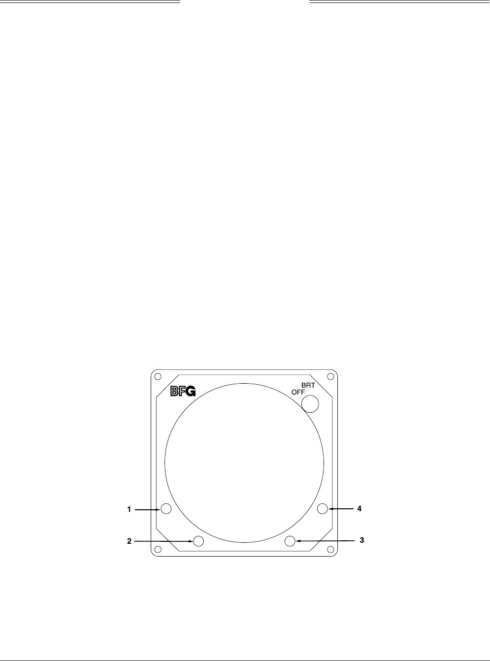
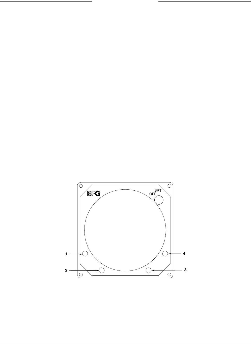
All operating controls are located on the front of the WX-1000/SKY497 display. Figure B-1 shows the
locations of the controls. Complete operating instructions for the SKY497 are provided in the SKY497
Pilot's Guide supplied with each system.
Figure B-1. Controls
OFF/BRT
Switch
Power is applied by rotating the knob clockwise past the detent. Continued
clockwise rotation increases display brightness.
1, 2, 3, & 4
Pushbuttons
Also referred to as soft-keys (1), (2), (3), and (4). In every operating mode a label
identifying the button function will be displayed next to the button.

SKY497
Installation Manual
B-2
Rev. C
B.3 CHECKOUT PROCEDURE
If the indications given in the following steps, except for the ramp test set, are not obtained, refer to the
troubleshooting procedures in Chapter 4. If indications given for the ramp test set are not obtained, refer
to the manual supplied with that equipment.
1. Enter and store the setup information identified in table B-1 (see next page) into the TCAS-201 Ramp
Test Set.
2.
Table B-1. IFR Systems TCAS-201 Ramp Test Set Setup Data
SCREEN STORAGE NUMBER 1
SETUP #1 INTRUDER TYPE: ATCRBS
UUT DIST: HORIZ = Distance (ft.) from aircraft
UUT DIST; VERT = Vertical height (ft.) difference between test
antenna and SKY497 antenna
ALT REPORTING: ON
STORE 0
RECALL 0
GAIN_1030 9.4 dB
LOSS 1.3 dB
SETUP #2 RANGE MAX: 20 NM
RANGE MIN: 0 NM
ALT MAX: 60,000 ft
ALT MIN: 0 ft
SCENARIO TEST RANGE: 5.0 NM
RANGE RATE: +200 kt
ALT: 51,000 ft
ALT: RATE: 0 FPM
REPLY TEST RANGE: 5.0 NM
ALTITUDE 50,500 ft
%REPLY: 100 %
3. Make sure the aircraft's transponder is in the STBY mode and the DME is turned OFF. At the
aircraft's instruments, verify all compass/HSI flags are valid.
NOTE
After power up, it may take a couple of minutes for the altitude encoder to
return a valid altitude to the transponder and SKY497.
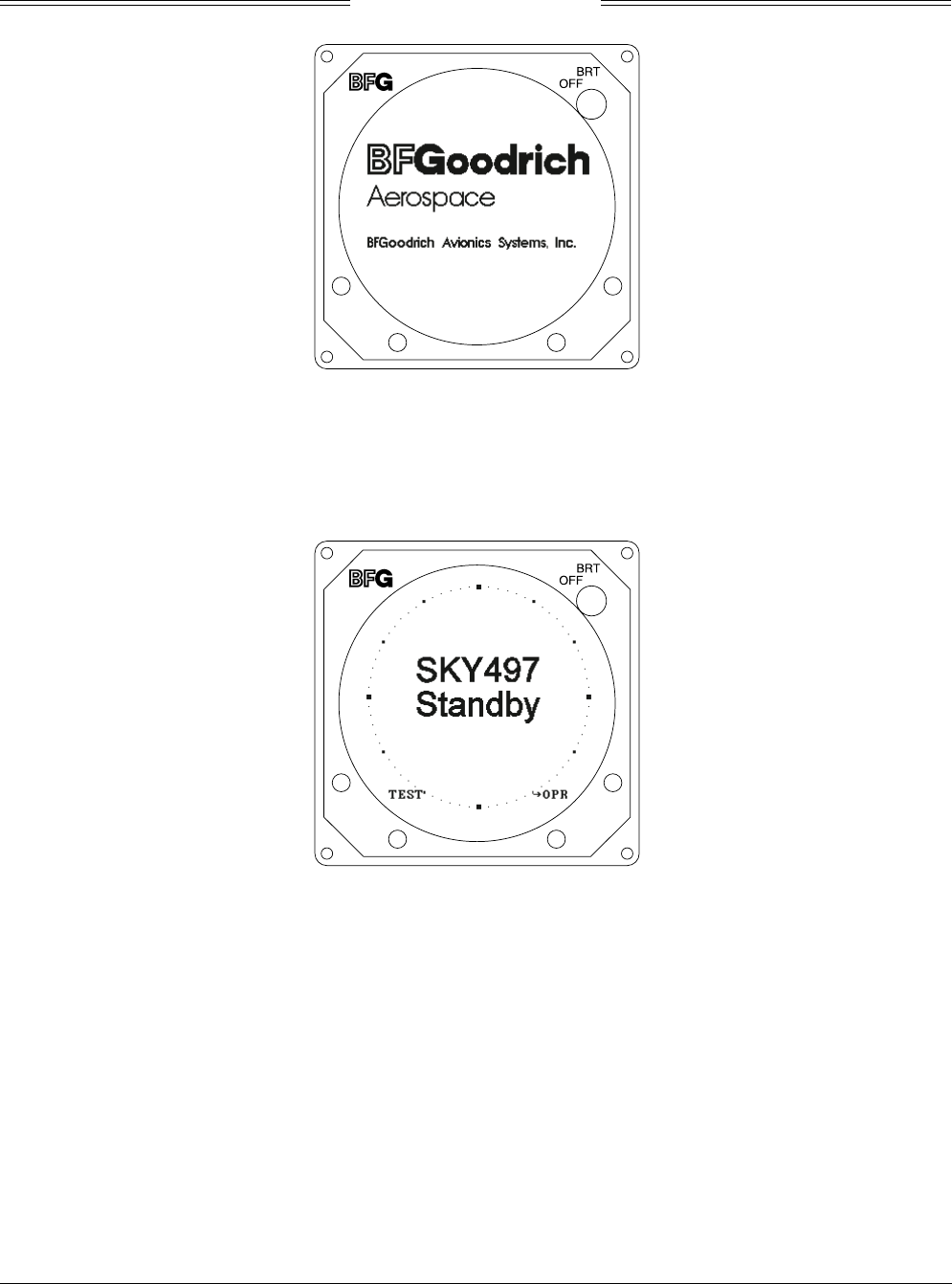
4. Turn SKY497 ON. The display will show a start-up screen similar to one shown in figure B-2. After
start-up screen appears, rotate the OFF/BRT switch. Verify that clockwise rotation increases display
brightness.
SKY497
Installation Manual
B-3
Rev. C
Figure B-2. Start-up Screen
After approximately thirty seconds the display will show the STANDBY screen (see figure B-3).
NOTE
If the TRC has not been calibrated to the directional antenna (see step 6
below), the display may show a “SKY497 FAILED” message.
Figure B-3. Standby Screen
5. Turn SKY497 OFF and then enter the Service Menu (see paragraph 4.4) by holding the left two
buttons (soft-keys 1 and 2) depressed as the system is turned ON.
6. From the Service Menu, calibrate the TRC to the directional antenna (see paragraph 4.4.1).
7. Return to the Service Menu and select System Data (see paragraph 4.4.3).
a. Verify status and save the configuration jumpers (see paragraph 4.4.3.2, Configuration).
b. Verify that the system has recognized and is responding to installed sensors (see paragraph
4.4.3.3, Data Monitor).
1) Sequence through each Data Monitor display page.
2) Verify that the sensor information displayed is correct.
3) If the information is not correct, the sensor has failed to communicate with the TRC.
Check operation of the sensor and cables between the TRC and sensor.

SKY497
Installation Manual
B-4
Rev. C
4) Change the status of the landing gear, squat switch, altitude, and heading sensors. Verify
that the display shows the correct input (i.e., sensing of these signals).
8. Exit the service menu and do the SKYWATCH self-test (see para 3.4).
9. Do the SKYWATCH self-test (see para 3.4).
10. Turn SKY497 OFF, return to the Service Menu and select Ground Test (see paragraph 4.4.4).
11. Verify operation of range function. Soft-key (3) is labeled to indicate the current range. Press soft-key
(3) to toggle the display range between 2 and 6 nm.
12. Select the 6 nautical mile range.
13. Verify that the system toggles through the altitude display modes. Soft-key (2) is labeled to indicate
the current mode. Press Soft-key (2) to select normal (NRM), below (BLW), and above (ABV).
14. Select the NRM (normal) mode.
15. Position the aircraft with the nose aligned on any 90 degree heading. Avoid areas within 250 ft of
obstructions (e.g., hangers, large aircraft, control towers, etc.) where there is a potential for multipath
problems. Locate and mark test points, every 30 degrees (i.e., at 000, 030, 060, 090, 120, 150, 180, 210,
240, 270, 300, and 330 degrees with respect to the SKY497 directional antenna). Mark these points at
the same distance, approximately 100 ft, from the aircraft.
16. Do the following static tests:
a. Connect the TCAS-201 Flat Antenna (facing towards the test aircraft) to the antenna connector.
b. At the TCAS-201 test set, press the REPLY TEST key.
c. Initiate the REPLY TEST by pressing the ANTENNA push button switch or the RUN/STOP
key.
NOTE
The TCAS-201 display will indicate “NO WHISPER-SHOUT SEQUENCE”.
d. Verify that the SKY497 display shows an other traffic symbol (open diamond) at the 12 O'clock
position (±30 degrees), approximately 5.0 nm, in level flight, and at an altitude of 500 ft above
own aircraft (i.e., "+05").
NOTES
If the display reflects a gross error in target bearing, check the directional
antenna cables at TRC connectors J9 (sum port) and J11 (difference port).
They may be reversed. A further indication of this condition would be a target
that moved in a counter-clockwise direction when the test set is moved in a
clockwise direction.
Multiple targets or a faulty bearing may result from multipath distortion
(see step 2).
During these tests, the SKY497 may detect and display other active targets.
e. Repeat a, b, c, and d from each of the test points (see step 2).
16. Do the following dynamic test.
a. Position the ramp test set on the test point directly in front of the test aircraft (i.e.,
approximately 100 ft in front of the aircraft, see step 2).
b. Connect the TCAS-201 Flat Antenna (facing towards the test aircraft) to the antenna connector.
c. At the TCAS-201 test set, press the SCEN key.
d. Initiate the SCENARIO TEST by pressing the ANTENNA push button switch or the
RUN/STOP key.

SKY497
Installation Manual
B-5
Rev. C
e. Verify that the display shows an "other traffic" symbol (open diamond) at the 12 o'clock position
(±30 degrees) approximately 5.0 nm and in level flight. The traffic symbol should be at an
altitude of 500 ft above own aircraft (i.e., "+05") and moving towards your aircraft.
f. When the target approaches closer than approximately 1 nm from own aircraft, verify that the
symbol changes from an other traffic symbol (open diamond) to a traffic advisory (solid circle).
NOTE
The voice message, “TRAFFIC, TRAFFIC,” will be enunciated over the
cockpit audio system.
g. The target, when it reaches 0.0 nm, will reverse direction and move outbound on the same
heading.
NOTE
The target may momentarily drop from the display and then reappear as an
other traffic symbol (open diamond).
17. Restart SKYWATCH by cycling power OFF and then ON.
18. This completes the post installation checkout procedure.

SKY497
Installation Manual
B-6
Rev. C
This page intentionally left blank.
SKY497
Installation Manual
C-1
Rev. C
APPENDIX C
INSTALLATION CHECKOUT
USING THE TIC T-49C FLIGHTLINE TESTER
C.1 INTRODUCTION
This section contains instructions for using the TIC T-49C Flightline Tester to do post-installation
checkout of the BFG Avionics Systems SKY497. Detailed setup, operation and maintenance information
for the T-49C Flightline Tester is provided in the T-49C Operating and Maintenance Instruction Manual.
NOTES
1. This procedure assumes familiarity with the set up and operation of the T-49C
Flightline Tester.
2. All test equipment used in completing these tests shall be calibrated in
accordance with the manufacturer's recommendations.
3. When the SKY497 is interfaced to an alternate display, reference Appendix E
while performing this checkout procedure.
This procedure will validate the installation and return to service of the BFGoodrich Avionics Systems
SKY497.
C.2 CONTROLS
All operating controls are located on the front of the WX-1000/SKY-497 display. Figure C-1 shows the
locations of the controls. Complete operating instructions for the SKY497 are provided in the SKY497
Pilot's Guide supplied with each system.
Figure C-1. Controls
OFF/BRT
Switch
Power is applied by rotating the knob clockwise past the detent. Continued
clockwise rotation increases display brightness.
1, 2, 3, & 4
Pushbuttons
Also referred to as soft-keys (1), (2), (3), and (4). In every operating mode a label
identifying the button function will be displayed next to the button.
SKY497
Installation Manual
C-2
Rev. C
C.3 CHECKOUT PROCEDURE
The T-49C Flightline Tester simulates a ground based secondary surveillance radar (SSR) when the TCAS
INTRUDER selector switch is in the ATCRBS/Mode-S XPDR TEST position. When the T-49C intruder
type switch is set to ATCRBS, the unit responds to ATCRBS Mode C interrogations. A varying delay time,
controlled from the microprocessor, delays the replies returned to the SKY497 from as far as 14 nautical
miles and as close as a few hundred feet. The apparent distance from the simulated intruder to the
SKY497 system under test decreases as if the intruder was converging on the aircraft under test. The test
set determines the altitude of the aircraft under test by interrogating the transponder using an ATCRBS
interrogation. By adding or subtracting the desired differential altitude, as selected by the front-panel
scenario switch, the initial altitude of the scenario is controlled by the microprocessor. This altitude, like
the distance, is varied so that the simulated intruder converges on the aircraft’s position.
1. Make sure the aircraft's transponder is in the STBY mode and the DME is turned OFF. At the
aircraft's instruments, verify all compass/HSI flags are valid.
NOTE
After power up, it may take a couple of minutes for the altitude encoder to
return a valid altitude to the transponder and SKY497.
2. Turn SKY497 ON. The display will show a start-up screen similar to one shown in figure C-2. After
start-up screen appears, rotate the OFF/BRT switch. Verify that clockwise rotation increases display
brightness.
Figure C-2. Start-up Screen
After approximately thirty seconds the display will show the STANDBY screen (see figure C-3).
NOTE
If the TRC has not been calibrated to the directional antenna (see step 4
below), the display may show a “SKY497 FAILED” message.
SKY497
Installation Manual
C-3
Rev. C
Figure C-3. Standby Screen
3. Turn SKY497 OFF and then enter the Service Menu (see paragraph 4.4) by holding the left two
buttons (soft-keys 1 and 2) depressed as the system is turned ON.
4. From the Service Menu, calibrate the TRC to the directional antenna (see paragraph 4.4.1).
5. Return to the Service Menu and select System Data (see paragraph 4.4.3).
a. Verify status and save the configuration jumpers (see paragraph 4.4.3.2, Configuration).
b. Verify that the system has recognized and is responding to installed sensors (see paragraph
4.4.3.3, Data Monitor).
1) Sequence through each Data Monitor display page.
2) Verify that the sensor information displayed is correct.
3) If the information is not correct, the sensor has failed to communicate with the TRC.
Check operation of the sensor and cables between the TRC and sensor.
4) Change the status of the landing gear, squat switch, altitude, and heading sensors. Verify
that the display shows the correct input (i.e., sensing of these signals).
6. Exit the Service Menu. Verify that the display shows the standby screen (figure C-3) and then press
Soft-key (4), labeled OPR.
7. Verify operation of range function. Soft-key (3) is labeled to indicate the current range. Press Soft-key
(3) to toggle the display range between 2 and 6 nm.
8. Select the 6 nautical mile range.
9. Verify that the system toggles through the altitude display modes. Soft-key (2) is labeled to indicate
the current mode. Press Soft-key (2) to select normal (NRM), below (BLW), and above (ABV).
10. Select the NRM (normal) mode.
11. If installed, turn the radio altimeter OFF.
12. Do the SKYWATCH self-test (see para 3.4).
13. Position the aircraft with the nose aligned on any 90 degree heading. Avoid areas within 250 ft of
obstructions (e.g., hangers, large aircraft, control towers, etc.) where there is a potential for multipath
problems. Locate and mark test points at 30 degree intervals (i.e., 000, 030, 060, 090, 120, 150, 180,
210, 240, 270, 300, and 330 degrees) with respect to the SKY497 directional antenna. Mark these
points at the same distance, between 100 and 150 ft, from the aircraft.

SKY497
Installation Manual
C-4
Rev. C
13a. Change the aircraft's transponder from STBY mode to the ON position.
14. Position the T-49C Flightline Tester on one of the test points identified in previous step.
CAUTION
The Flightline Tester is not weatherproof when the lid is open. Do not setup
or operate the Flightline Tester in conditions of rain, sleet, etc.
15. Setup and verify operation of the T-49C Flightline Tester with the HI/LOW power switch in the HI
position and then:
a. Set the TCAS INTRUDER selector switch of the T-49C to the ATCRBS/Mode-S XPDR TEST
position and press TEST and the INTERROGATE. This will store the aircraft’s barometric
altitude in the T-49C.
NOTE
The T49-C will display the pressure altitude of the aircraft under test.
b. Verify that the SKY497 display shows the standby screen (figure C-3) and then press soft-key
(4), labeled OPR. Select NRM mode and 6 nm range by pressing appropriate soft-key's.
c. Set the TCAS INTRUDER selector switch to the ATCRBS position and the SCENARIO selector
switch to the 0 altitude offset position. Press INTERROGATE, and when the range on the
display decreases to 5 NM, press TEST. This will freeze the scenario and represent a stationary
intruder aircraft 5 NM away at the same altitude as the UUT aircraft. Verify that the SKY497
displays, in the direction (±30 degrees) of the T-49C, a symbol for other traffic (i.e., open
diamond) at 5 NM. Target will be displayed in level flight at own aircraft altitude (i.e., “00”
displayed above the traffic symbol).
NOTES
1) If the display reflects a gross error in target bearing, check the SKY497
directional antenna cables at TRC connectors J9 (sum port) and J11
(difference port). They may be reversed. A further indication of this
condition would be a target that moved in a counter-clockwise direction
when the T-49C is moved in a clockwise direction.
2) Multiple targets or a faulty bearing may result from multipath distortion
(see step 1).
3) During these tests, the SKY497 may detect and display other active
targets.
4) To obtain a better line of sight, it may be necessary to elevate the
antenna.
d. Move the T-49C to each test point and verify that the display shows the corresponding bearing
displacement.
NOTE
It is necessary to wait a few seconds after moving to let the test target stabilize
in position.
16. This completes testing with the T-49C, reattach top lid of the T-49C.
17. If installed, TURN ON the radio altimeter.
18. This completes the post installation checkout procedure.

SKY497
Installation Manual
D-1
Rev. C
APPENDIX D
Using the Terminal Device
(e.g., Laptop Computer)
A terminal device can be used as an aid in installing, testing and troubleshooting the SKY497. The
terminal device must be connected to the RS-232 serial data TEST port (J7) located on the front of the
TRC497. TRC connector J7 is a female DB9 receptacle. A standard serial cable that has RXD (pin 2), TXD
(pin 3), and GND (pin 5) can be used. Any computer, with RS-232 terminal emulation software (e.g.,
Procomm, HyperTerminal, etc.), may be used as the terminal device. To communicate with the TRC, the
RS-232 terminal device must be setup as follows, with no hardware or software handshaking being used.
Baud Rate: 19200
Parity: None
Data Bits: 8
Stop Bits: 1
The SKY497 includes the following commands to help with installation, testing, and troubleshooting.
These commands are listed in the order they appear when the help menu is accessed and can be typed in
upper case or lower case letters. Ctrl+R repeats the last command once; Ctrl+L continually repeats the last
command (to stop continuously repeating the command press <Enter>). Help screens have been created for
your convenience, to access the command help screen type help or ? at the prompt. To access the help
screen for each command, type the command followed by help.
Commands Descriptions
? or Help The help or ? command displays a list of available commands. Executing the
Help command displays the following list.
stp>?
? .................... Command help
Arinc429 ............. Arinc 429 cmds
Arinc735 ............. Arinc 735 cmds
Bar .................. Displays barometric altitude
Cal .................. Executes antenna calibration
Config ............... SKY497 Config Options
Dump ................. Displays the List of Logged Errors
Ground ............... Turns ground test mode on or off
Head ................. Displays heading
Help ................. Command help
Rad .................. Displays Radio altitude
Save ................. Saves System Configuration
Say .................. Says Phrase from Speech Chip
Sensors .............. Displays sensor data
Version .............. SW Version information
For Information on any particular command, enter the command followed
by help.

SKY497
Installation Manual
D-2
Rev. C
Commands Descriptions
Arinc429 Displays the ARINC-429 sensor inputs and label status. Data shown is live
and will change as the sensor changes. To view changes re-type the
command.
stp>Arinc429
Arinc429 Operating,
Rx: Seeking, Low
Rx Parity Errors: 0
Lbl Functn Chn Ssm Value
164 RadAlt --- --- ------
203 BarAlt --- --- ------
320 MagHead --- --- ------
Arinc735 Displays the ARINC-735 alternate display type and status. Data shown is
latched during turn on, configuration changes will not take affect until
power is cycled.
stp>arinc735
Tx Selected: None Selected
stp>arinc735
Tx Selected: ARINC735 Type1
stp>arinc735
Tx Selected: Illegal Display
Bar (help) Displays the barometric altitude source, validity, and value. Data shown is
live and will change as the sensor changes. To view changes re-type the
command.
Bar help: Displays the command specific help message.
Bar: Displays barometric altitude data.
stp>bar
Barometric Altitude source: Encoded Inputs
Barometric Altitude: 1000 feet
Encoded Altitude Bits
d4 c4c2c1 b4b2b1 a4a2a1
0 0 1 0 0 1 1 0 0 0
Encoded Altitude: 1000 feet

SKY497
Installation Manual
D-3
Rev. C
Commands Descriptions
Cal (help) Calibrates the antenna to the system (includes cables, connectors, and
TRC497).
Cal: Performs system calibration.
stp>cal
Asking for current calibration value.
Starting calibration. Please Wait...
Re-Calibration Successful!
Old Cal Value: 283 degrees
New Cal Value: 273 degrees
Cal help: Displays the command specific help message.
Config Displays the state of the configuration pins, switches, barometric altitude
bits, and internal voltage and temperature readings. Checks the
input/output circuitry. Data shown is live and will change as the sensor or
configuration changes. To view changes re-type the config command.
stp>config
SKY497 Configuration Straps:
Hdg. (XYZ/STEP/429): XYZ
P1-70 : GND
P1-69 : OPEN
Heading Flag Sense : HIGH
P1-68 : GND
DR/Alt.422 (DR/422): DR
P1-67 : OPEN
Ant. Pos. (TOP/BOT): TOP
P1-100 : OPEN
Antenna NY(164/156): NY164
P1-99 : OPEN
Airframe (FIX/ROT): FIX
P1-98 : OPEN
Alternate Display Type: None Selected
P1-80 : OPEN
P1-79 : OPEN
P1-78 : OPEN
P1-77 : OPEN
IOP Soft Switches:
Squat (ON GND/FLY): ON GND
P1-88 : GND
Gear (UP/DOWN): DOWN
P1-87 : GND
GPWS (ACT/INACT): INACT
P1-32 : OPEN
Barometric Encoded Altitude:
d4 c4c2c1 b4b2b1 a4a2a1
0 0 1 0 0 1 1 0 0 0
Altitude: 1000 feet
a1=P1-40 b1=P1-51 c1=P1-58
a2=P1-41 b2=P1-56 c2=P1-59
a4=P1-50 b4=P1-57 c4=P1-71
d4=P1-72
IOP Internal Status:
Internal +5 VDC: +5.1 V
Internal +15 VDC: +15.0 V
Internal -15 VDC: -15.1 V
Internal Temp. : +34 C

SKY497
Installation Manual
D-4
Rev. C
Commands Descriptions
Dump (help) Displays the error messages stored in the error log. If no errors are stored in
the system log, the message NO FAULTS DETECTED is displayed.
Dump help: Displays command specific help message.
Dump: Displays system error log.
stp>dump
SKY497 SYSTEM LOG
System Time - 00704:14
Err# Time Description
019 - 00693:41 - RF Transmitter
018 - 00668:47 - RF Angle
020 - 00668:03 - Barometric Altitude Input
024 - 00647:52 - Processor Reset
153 - 00647:38 - HDG
Ground (help | test | off) SKY497 enters the ground test mode.
Ground help: Displays the command specific help message.
Ground (or Ground 0ff): Exits ground test mode (if active).
Ground Test: Enters ground test mode.
stp> ground help
Parameter:
TEST to enter ground test mode or OFF (or nothing) to exit mode
stp>ground
System no longer in Ground Test Mode
Returning to aircraft sensors and switch inputs
stp> ground test
System in Ground Test Mode
Simulating Barometric Altitude: 50,000 ft.
Simulating RADAR Altimeter: 2,500 ft.
Simulating Heading: 0 deg
Gear and Squat switch override in effect
Head (help) Displays the current heading source, degrees, and heading flag status (valid
or invalid). Heading source is latched during turn on and will not change
until power is cycled, all other data is live.
Head help: Displays the command specific help message.
Head: Displays heading data.
stp>head
Heading Source: Synchro XYZ
Heading: 0 degrees
Flag line: Valid

SKY497
Installation Manual
D-5
Rev. C
Commands Descriptions
Help or ? The help or ? command displays a list of available commands. Executing the
Help command displays the following list.
stp>?
? .................... Command help
Arinc429 ............. Arinc 429 cmds
Arinc735 ............. Arinc 735 cmds
Bar .................. Displays barometric altitude
Cal .................. Executes antenna calibration
Config ............... SKY497 Config Options
Dump ................. Displays the List of Logged Errors
Ground ............... Turns ground test mode on or off
Head ................. Displays heading
Help ................. Command help
Rad .................. Displays Radio altitude
Save ................. Saves System Configuration
Say .................. Says Phrase from Speech Chip
Sensors .............. Displays sensor data
Version .............. SW Version information
For Information on any particular command, enter the command followed
by help.
Save Saves all configuration jumper settings into system memory. Once the data
is written to memory the saved configuration data is displayed on the
terminal device. The system configuration is read on power up and compared
to the current jumpers. If the jumpers disagree with the saved memory, an
Error 30 will occur. Configuration jumpers can also be read by typing the
Config command.
stp>save
Saving SKY497 Config Straps:
Configuration P1-70, Heading. set to Ground.
Configuration P1-69, Heading. set to Open.
Configuration P1-68, HeadFlgSen set to High.
Configuration P1-67, DR/Alt.422 set to Data Rec.
Configuration P1-100, Ant.Pos. set to Top.
Configuration P1-99, Ant.Type set to NY-164.
Configuration P1-98, Airframe set to Fixed Wing.
Configuration P1-80, AltDispType set to Open.
Configuration P1-79, AltDispType set to Open.
Configuration P1-78, AltDispType set to Open.
Configuration P1-77, AltDispType set to Open.
Say (help | 1-4) Forces the TRC to announce one of four commands, depending on the
number (1 thru 4) entered after the command SAY. Can be used to help
troubleshoot audio output problems.
say help: Displays command specific help message.
say 1: Traffic Avoidance System Test
say 2: Passed
say 3: Failed
say 4: Traffic! Traffic!

SKY497
Installation Manual
D-6
Rev. C
Commands Descriptions
Sensors (help) Displays the current source and value for the heading, barometric altitude,
and radio altitude.
Sensors help: Displays command specific help message.
Sensors: Displays current sensor status.
stp>sensors
Heading source: Synchro XYZ
Heading is Valid, 0 degrees
Barometric Altitude source: Encoded Inputs
Barometric Altitude is Valid, 1000 feet
Radio Altitude source: ARINC 429
Radio Altitude is Invalid
Version Displays the versions for the IOP Code, IOP Boot, STP Code, and STP Boot
software. Contact customer service department for version information.
stp>version
IOP Code X.XX
IOP Boot X.XX
STP Code X.XX
STP Boot X.XX

SKY497
Installation Manual
E-1
Rev. C
APPENDIX E
Installation Checkout Using
an Alternate Display
E.1 INTRODUCTION
This section contains installation checkout procedures for the SKY497 that is interfaced to an alternate
display (e.g., BFGoodrich Avionics Systems RGC250).
NOTES
1. This section provides checkout information for the BFGoodrich Avionics
Systems SKY497 interfaced to an Alternate Display. When interfacing to an
alternate display the TRC497 must have software version 1.4 or above.
2. This procedure assumes familiarity with the set up and operation of the TT391
Flightline Tester and RS-232 terminal device (see Appendix D). If using
another approved tester refer to the appropriate appendices for test procedure.
3. All test equipment used in completing these tests shall be calibrated in
accordance with the manufacturer's recommendations.
This procedure will validate the installation and return to service of the BFGoodrich Avionics Systems
SKY497.
E.2 CONTROLS
Operating instructions for each alternate display are provided with the display manufacturers
documentation.
NOTE
When using an alternate display all SKY497 functions are controlled through
the alternate display. Each alternate display will show information consistent
with the capabilities of that particular display. Therefore, the text displayed
may be different from what is called out in this procedure. Reference the
alternate display documentation for appropriate screen text.
E.3 CHECKOUT PROCEDURE
The TT391 Flightline Tester simulates both a ground based secondary surveillance radar (SSR) and an
airborne transponder. With the SKY497 set to GROUND TEST (i.e., the barometric altimeter is simulated
to 50,000 ft, heading simulated to 0 degrees, and the radar altimeter simulated to 2,500 ft) the TT391 will
simulate two targets; a Traffic Advisory (i.e., a solid circle) at ¼ nm and Other Traffic (i.e., open diamond)
at 4.5 nm. Both targets will be displayed in level flight at own aircraft altitude (i.e., "00" displayed above
the traffic symbol).
If the indications given in the following procedure, except for the Flightline Tester, are not obtained, refer
to the troubleshooting procedures in Chapter 4. If indications given for the Flightline Tester are not
obtained, refer to the maintenance section of the TT391 Instruction Manual.
1. Connect the RS-232 terminal device to J7 TEST port on the TRC497. Setup and turn on the terminal
device. (See Appendix D for terminal device commands, setup, and operating instructions.)
2. Make sure the aircraft's transponder is in the STBY mode and the DME is turned OFF. At the
aircraft's instruments, verify all compass/HSI flags are valid.

SKY497
Installation Manual
E-2
Rev. C
NOTE
After power up, it may take a couple of minutes for the altitude encoder to
return a valid altitude to the transponder and SKY497.
3. Turn SKY497 ON. After approximately thirty seconds the display will show the standby screen.
NOTE
If the TRC has not been calibrated to the directional antenna, the display may show
a FAIL message. Calibrate the system (see step 4 below).
4. At the terminal device, type Cal <Enter>. Verify the Re-Calibration Successful! is displayed.
5. Type Config <Enter>. Verify status of the configuration jumpers displayed on the screen. (You may
need to page up in order to see all of the data. See Appendix D for example.) Once correct
configuration is verified type Save <Enter>.
Change the status of the landing gear, squat switch, and altitude sensors. Type Config <Enter> again
and verify that the displayed information changed correctly (i.e., sensing of these signals).
6. At the terminal device, type the commands listed below. For each command verify the sensor
information displayed is correct (see Appendix D for examples). If the information is not correct, the
configuration setting may be wrong or the sensor communication with the TRC may have failed.
Check operation of the sensor and cables between the TRC and sensor.
Arinc429 <Enter>
Arinc735 <Enter>
Bar <Enter>
Rad <Enter>
Head <Enter> (Change heading of aircraft and verify heading changes.)
7. At the alternate display, perform the SKYWATCH self-test (see paragraph E.3.1).
8. At the terminal device, type Ground Test <Enter>.
9. At the alternate display, change the display ranges (if applicable) and verify display patterns are
correct.
10. Select the 6 nautical mile range.
11. Change the altitude display modes from normal (NRM), below (BLW), and above (ABV). Verify that
the system toggles through the altitude display modes correctly.
12. Select the normal (NRM) mode.
13. Position the aircraft with the nose aligned on any 90 degree heading. Avoid areas within 250 ft of
obstructions (e.g., hangers, large aircraft, control towers, etc.) where there is a potential for multipath
problems. Locate and mark test points at 30 degree intervals (i.e., 000, 030, 060, 090, 120, 150, 180,
210, 240, 270, 300, and 330 degrees) with respect to the directional antenna. Mark these points at the
same distance, between 100 and 150 ft, from the aircraft.
14. Position the TT391 Flightline Tester on one of the test points identified above.
CAUTION
The Flightline Tester is not weatherproof when the lid is open. Do not setup
or operate the Flightline Tester in conditions of rain, sleet, etc.
15. Setup and verify operation of the TT391 Flightline Tester:
a. Open the chassis lid and remove the lid from the chassis by sliding the lid off of the hinge pins
(sliding it to the right). The lid "stay" must be removed from the lid before mounting. The stay
will pop off of the lid. (The stay is the hinged part that props the lid open on the chassis).
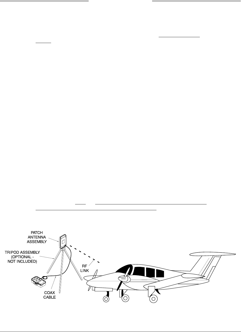
SKY497
Installation Manual
E-3
Rev. C
NOTE
The Patch Antenna may be used without a tripod. The Patch Antenna can be
held, or secured, and pointed towards the SKYWATCH aircraft under test
WITH THE MOUNTING STUD POINT TOWARD THE GROUND. This orientation is
critical.
b. Mount the chassis lid, with the Patch Antenna facing the aircraft, onto a tripod (not included).
The tripod must be capable of holding the antenna (approximately 2.5 lb) and must provide a
standard base mounting stud threaded 1/4"-20. A typical tripod mount is shown in figure E-1.
c. If the internal batteries are being utilized, proceed to sub-step f. If the Flightline Tester AC
Converter Power Supply is to be utilized, proceed to sub-step d.
d. Connect the AC Converter Power Supply cable connector to the chassis external connector.
e. Connect the AC Converter Power Supply input power cable connector to one of the following AC
sources:.
•115 Vac, 60 Hz
•115 Vac, 400 Hz
f. Set the Flightline Tester POWER switch to the ON position.
g. Verify that the LOW indicator is not steady on (it may flash). If the LOW indicator remains on
(i.e., lit), perform one of the following three options:.
•Use the AC Converter Power Supply to power the unit.
•Recharge the internal batteries.
•Replace the internal batteries.
h. Set the SELF-TEST switch to the 1030 position and verify that the 1030 indicator blinks on for
1/2 second every 5 seconds.
i. Set the SELF-TEST switch to the 1090 position and verify that the 1090 indicator blinks on for
1/2 second every 5 seconds.
j. Set SELF-TEST switch to center position (off). Set the POWER switch to the OFF position.
NOTE
Care should be taken to ensure that the Patch Antenna is connected to TT391
connector J1 and NOT J2. IF THE PATCH ANTENNA IS CONNECTED TO
J2 THE TT391 WILL NOT FUNCTION CORRECTLY.
k. Connect the Flightline Tester coax cable to J3 on the Patch Antenna and to connector J1 in the
chassis. (J2 should remain capped by the dust cover).
Figure E-1. Typical Patch Antenna Tripod Mount

SKY497
Installation Manual
E-4
Rev. C
16. From each test point (see step 13):
a. Position the TT391 Patch Antenna facing the SKYWATCH aircraft under test.
b. Set the TT391 POWER switch to the ON position.
c. Verify that the display shows, in the direction (± 30 degrees) of the TT391, two targets; a Traffic
Advisory (i.e., a solid circle) at ¼ nm and Other Traffic (i.e., open diamond ) at 4.5 nm. Both
targets will be displayed in level flight at own aircraft altitude (i.e., "00" displayed above the
traffic symbol).
NOTES
1. If the display reflects a gross error in target bearing, check the directional
antenna cables at TRC connectors J9 (sum port) and J11 (difference port).
They may be reversed. A further indication of this condition would be a
target that moved in a counter-clockwise direction when the TT391 is
moved in a clockwise direction.
2. Multiple targets or a faulty bearing may result from multipath distortion
(see step 1).
3. During these tests, the SKY497 may detect and display other active
targets.
4. To obtain a better line of sight, it may be necessary to elevate the patch
antenna.
d. Set the TT391 POWER switch to the OFF. Repeat procedure from each test point. Step 16 can
be done from the last test point.
NOTE
To prevent SKYWATCH from tracking the movement of the test-set, it is
necessary to set the TT391 POWER switch to OFF after completing each
bearing measurement.
17. Return the TT391 assemblies to their position in the aluminum carrying case.
18. Restart SKYWATCH by cycling power OFF and then ON.
19. Connect an oscilloscope to the suppression bus and verify that the SKY497 suppression pulse (100 µs
±5 µs) exceeds +15 Vdc. If less than +15 Vdc, the suppression bus is overloaded. Check all equipment
connected to the bus. Repair/replace the offending device.
20. This completes the post installation checkout procedure.

SKY497
Installation Manual
E-5
Rev. C
E.3.1 Self Test
1. Turn SKYWATCH OFF and then:
a. Make sure the aircraft's transponder is in the STANDBY, ON, or ALT mode.
NOTE
After power up, it may take a couple of minutes for the altitude encoder to
return a valid altitude to the transponder and SKY497.
b. If installed, power up the radio altimeter.
c. Make sure all compass/HSI flags are cleared from the aircraft's instruments.
2. Turn SKYWATCH ON.
3. After approximately thirty seconds, observe the standby screen and then perform the SKYWATCH
self test (see alternate display operating instructions on how to perform self test).
4. If SKYWATCH passes the self-test, the system will return to the standby screen and the voice
message, "TRAFFIC ADVISORY SYSTEM TEST PASSED," will be enunciated over the cockpit audio
system.
5. If you do not hear the voice message or if the voice message is of insufficient volume:
a. Check headphones/speaker and aircraft audio panel switch settings.
NOTE
Audio levels are adjusted at the aircraft audio panel. There is no internal
audio adjustment.
b. Check audio connection to the TRC:
1) 600-ohm audio systems should be connected to P1-92 (AUDIO_H).
2) 150-ohm audio systems should be connected to P1-91 (AUDIO_L).
3) Audio common is connected to P1-90 (AUDIO_C).
NOTE
Audio output from the TRC is transformer isolated.
6. If SKYWATCH fails the self-test:
a. The fail screen will be displayed.
b. The voice message, "TRAFFIC ADVISORY SYSTEM TEST FAILED", will be enunciated over the
cockpit audio system.
c. Refer to the fault isolation procedures and error messages in Chapter 4.

SKY497
Installation Manual
E-6
Rev. C
This page intentionally left blank.