L 3 Communications Avionics Systems TRC497 SkyWatch Traffic Advisory System User Manual Pilot s Guide for SKYWATCH SKY497
L-3 Communications, Avionics Systems SkyWatch Traffic Advisory System Pilot s Guide for SKYWATCH SKY497
Contents
Pilots guide part 2 of 2
Pilot’s Guide 2-1
SKY497
Operating Instructions
Chapter 2
Operating Instructions
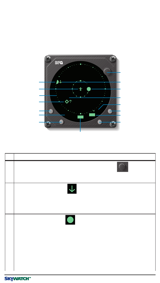
Controls & Indicators
Figure 2-1 identifies the major controls and on-screen indicators for the
SKY497
. Table
2-1 is the legend for figure 2-1 and lists other controls and indicators.
Table 2-1. SKY497 Controls and Indicators
ABV6nm
STB
+10
+02
+05
HDG
BRT
OFF
13
15
11
2
4
6 Operating Mode n
7 Button
8 Display Range
Button
16
5
3
10
14
Altitude Display
Mode Button
Test Button 12
Figure 2-1. SKY497 Controls and Indicators
1 Power/Brightness
Control Knob
9
SKY497 Pilot’s Guide
No Description
1 Power/BrightnessControlKnob(
OFF/BRT
)
Thepower/brightnesscontrolknobcontrolspowertothe
SKY497
and
WX-1000
(ifinstalled) andadjustsdisplay brightness.
2 VerticalTrendArrow
Averticaltrendarrowindicatesthattheintruderaircraftisascending
(uparrow)ordescending(downarrow)fasterthan500fpm. Noarrow
isshownforintruderaircraftin level flight, orforthosemovingvertically
slowerthan500fpm, orfornon-altitude-reportingintruderaircraft.
3 TrafficAdvisory(TA)
ATAconsistsofasymbolon-screen anda“traffic,traffic”messageon
thecockpit speakersorheadset.Whenanintruderaircraftthatmeets
theTAcriteriadescribedin chapter3iswithinthedisplayedrange
(insideoroutsideoftheselectedaltitudedisplay mode),the
correspondingsymbolisthiscirclelocatedataposition onthescreen
thatindicatestherelativebearingandrangeoftheintruderaircraft.
Ingeneral,The
SKY497
issuesaTAwhen it detectsanintruderaircraft
within30secondsofapossiblecollision,orwithina0.5nmi horizontal
radiusanda±800ftrelativealtituderangeofyouraircraft.
2-2 Pilot’s Guide
Operating Instructions
SKY497
Table 2-1. SKY497 Controls and Indicators (Continued)
No Description
4 Data Tag
These two digits indicate, in hundreds of feet, the relative altitude of the
intruder aircraft. For example, +10 means the intruder aircraft is
1,000 feet above you. A positive data tag is displayed above the traffic
symbol to emphasize that the intruder aircraft is above your aircraft.
Similarly, a negative data tag is displayed below the traffic symbol. If the
intruder is at the same altitude as your aircraft, 00 will be displayed
above the traffic symbol.
The data tag for a vertically out of range TA stays at the maximum or
minimum altitude number of the current altitude display mode until the
intruder aircraft comes within the altitude limits of the altitude display
mode. The
SKY497
only displays data tags for altitude reporting aircraft.
5 Operating Mode Button Label
This on-screen label identifies the function of the adjacent button. The
>
OPR
label appears on the standby screen and means
go to normal
operating mode
.The>
STB
label appears on the traffic screen and
means
go to standby
. If your aircraft has a squat switch, the >
STB
label only appears when your aircraft is on the ground.
6 Operating Mode Button
Pressing the operating mode button when it’s labeled >
STB
switches
the
SKY497
out of normal operating mode and into standby. Pressing
the button when it’s labeled >
OPR
switches the
SKY497
out of standby
and into normal operating mode.
7 Display Range Indicator
This indicator identifies the currently selected display range (6 or 2
nmi). The indicator does not appear when the
SKY497
is in standby.
8 Display Range Button
This button toggles the
SKY497
display range between 6 and 2 nmi as
reflected in the on-screen display range indicator. Pressing the button
when the
SKY497
is in standby has no effect.
9 Heading Flag
The heading flag appears when the heading input is invalid or missing.
The heading flag will disappear when a valid heading signal is supplied.
The
SKY497
will
operate with a heading flag, but you may experience
degraded performance, especially during high-rate-of-turn maneuvers.
10 Altitude Display Mode Button
This button changes the
SKY497
altitude display mode in the following
order: above, normal, below, normal, etc., as reflected in the on-screen
altitude display mode indicator. Pressing the button when the
SKY497
is
in standby has no effect.
6nm
HDG
+10
STB
Pilot’s Guide 2-3
SKY497
Operating Instructions
Table 2-1. SKY497 Controls and Indicators (Continued)
ABV
No Description
11 Altitude Display Mode Indicator
This indicator displays the name of the currently selected altitude display
mode:
ABV
(look up),
BLW
(look down), or
NRM
(normal). This indicator
does not appear when the
SKY497
is in standby.
12 Test Button
This button starts a
SKY497
self test when the
SKY497
is in standby.
13 Other Traffic
This symbol represents traffic detected within the selected display range
and altitude display mode that does not generate a TA.
14 Range Rings
The outer range ring represents a distance of 6 nmi from your aircraft
when the display is set on the 6 nmi range, or a distance of 2 nmi when
the display is set on the 2 nmi range. The inner range ring on the 6 nmi
range represents a distance of 2 nmi.
15 Own Aircraft
This symbol represents your aircraft.
16 Out-of-Range Traffic Advisory
An out-of-range TA is one in which the intruder aircraft is beyond the
displayed range. The corresponding symbol is this semicircle located at
a position along the outer range ring that indicates the relative bearing
of the intruder aircraft.
Controls Required with the
STORMSCOPE
Option:
–
SKYWATCH/STORMSCOPE
Mode Switch (not shown)
This remote toggle switch determines whether traffic information or
thunderstorm information is displayed on the screen.
Both the
SKY497
and the
WX-1000
continue their tracking functions even
if the switch is in the other position. If the
SKY497
detects a TA or
generates an error message when the switch is in the
STORMSCOPE
position, the display will switch to the traffic screen until the TA or error
message disappears.
–
WX-1000
Maintenance Switch (not shown)
This remote toggle switch (normally installed in the avionics bay) has a
Normal position and an Override (
WX-1000
maintenance) position. It
should only be moved to the Override position when the
WX-1000
processor is removed or powered down at the circuit breaker, and you
still want to use the
SKY497
.

2-4 Pilot’s Guide
Operating Instructions
SKY497
Table 2-1. SKY497 Controls and Indicators (Continued)
No Description
Aural Announcements:
–“Traffic Traffic”
This aural component of a traffic advisory is announced once over the
cockpit speakers or headset when a TA aircraft is first detected.
–“Traffic Advisory System Test Passed”
This message is announced once over the cockpit speakers or headset
after the
SKY497
has passed an operator-initiated self test.
–“Traffic Advisory System Test Failed”
This message is announced once over the cockpit speakers or headset
after the
SKY497
has failed an operator-initiated self test.
Turn On the SKY497
To avoid power surges that could damage the
SKY497
and the optional
WX-1000
, start your engines before turning on the
SKY497
.
1. Turn the
OFF/BRT
knob clockwise to the desired display brightness.
The
BFG
oodrich screen (figure 2-2) appears and stays on the display until the power-
on self test is complete.
If the
SKY497
passes the test, and your aircraft has a squat switch, and your aircraft is
on the ground, the standby screen appears (figure 2-3).
If the
SKY497
passes the test, and your aircraft has a squat switch, and your aircraft is
in the air, the traffic screen appears set on the 6 nmi display range and the normal
altitude display mode (figure 2-4).
If the
SKY497
passes the test and your aircraft does not have a squat switch, the
standby screen appears (figure 2-3).
If a Failed screen similar to figure 2-5 appears, refer to the Failure Response section
on page 2-9. (For installations with an
ARINC 429
barometric altitude input, turning
on the
SKY497
during flight causes a temporary Error 20 message while the system is
syncing up to the
429
data source.)
Run the Operator-Initiated Self Test
You should run the operator-initiated self test before the first flight of the day or as specified
in your Aircraft Operating Manual (
AOM
).
1. With the
SKY497
in standby, press the test button.
The
SKY497
begins its self test and the test screen (figure 2-6) appears. Upon
successful completion of the self test, you will hear “Traffic Advisory System Test
Passed” and the display will revert to the standby screen.
Pilot’s Guide 2-5
SKY497
Operating Instructions
OPRTEST
Standby
SKY497
BRT
OFF
BFGoodrichAvionicsSystems,Inc.
BRT
OFF
Figure 2-2. BFGoodrich Screen Figure 2-3. SKY497 Standby Screen
TEST
Failed
SKY497
Error
ProcessorComm.
145
BRT
OFF
NRM 6nm
-13
+01
+25
+10
+05
BRT
OFF
Figure 2-4. In-Flight Traffic Screen Figure 2-5. SKY497 Failed Screen
2.If you hear “Traffic Advisory Sys-
tem Test Failed” or see a
SKY497
Failed screen (figure 2-5), push
the test button again. If it contin-
ues to fail, refer to the Failure
Response section on page 2-9.
3.If you hear “Traffic Advisory Sys-
tem Test Passed” without seeing
the test screen, turn off the
SKY497
using the
OFF/BRT
knob
and contact your authorized
BFGoodrich Avionics Systems
dealer for troubleshooting help.
6nm
NRM
SYSTEMTEST
INPROGRESS
-10
+10
-02
BRT
OFF
Figure 2-6. Operator-Initiated Test Screen
2-6 Pilot’s Guide
Operating Instructions
SKY497
Switch Between Standby and Normal Operating Mode
You must switch out of standby if you want the
SKY497
to display traffic information. The
ability to switch out of standby on the ground in conjunction with the above display mode
is especially useful for scanning the airspace around the airport before takeoff.
1.To switch into normal operating mode from the standby screen (figure
2-3), press the button labeled
>>>>>OPR
.
The
SKY497
switches out of standby into the above display mode and 6 nmi range.
(See figure 2-7.)
If your aircraft has a squat switch and you don’t manually switch out of standby, the
SKY497
will automatically switch out of standby 8 to 10 seconds after takeoff.
2.To switch into standby from the traffic screen (figure 2-7), press the button
labeled
>>>>>STB
.
The
SKY497
goes into standby and the display switches back to the standby screen.
If your aircraft has a squat switch, the
>STB
button label is not displayed while you’re
airborne and the
SKY497
will not go into standby while airborne, but will automati-
cally go into standby 24 seconds after landing. (This delay allows the
SKY497
to
remain out of standby during a touch-and-go maneuver.)
Change the Display Range
You can change the display range anytime your aircraft is not in standby.
1.Press the display range button to toggle the display range between 6 & 2
nmi. (See figures 2-7 and 2-8.)
With each press of the button, the screen changes to display the traffic detected
within the chosen display range. The numerical value of the chosen display range (2
nm or 6 nm) is displayed next to the button.
The
SKY497
continues to track up to 30 intruder aircraft within its maximum
surveillance range regardless of the display range selected.
Figure 2-7. Traffic Screen Set on 6 nmi Range Figure 2-8. Traffic Screen Set on 2 nmi Range
ABV2nm
+01
BRT
OFF
STB
ABV6nm
+13
+01
+10
STB
+05
BRT
OFF
Pilot’s Guide 2-7
SKY497
Operating Instructions
Change the Altitude Display Mode
You can change the altitude display mode anytime your aircraft is not in standby.
1.Press the altitude display mode button to toggle the altitude display mode
between above, normal, and below.
With each press of the button, the screen changes to display the traffic detected
within the chosen altitude display range. (See figure 2-9.) The name of the chosen
altitude display mode (
ABV
,
NRM
, or
BLW
) is displayed next to the button.
The
SKY497
continues to track up to 30 intruder aircraft within its maximum
surveillance range regardless of the altitude display mode selected.
Own Aircraft
6 nmi
6 nmi
Below
Display Mode (Look Down) (BLW)
Above
Display Mode (Look Up) (ABV)
Normal (NRM)
+2700 ft
–2700 ft
+9000 ft
Intruder Aircraft
–9000 ft
Not To Scale
0 ft
Figure 2-9. Altitude Display Modes

2-8 Pilot’s Guide
Operating Instructions
SKY497
Switch Between SKYWATCH and STORMSCOPE Modes (Optional)
If you have a
STORMSCOPE WX-1000
installed with the
SKY497
, you can switch between
SKYWATCH
and
STORMSCOPE
screens (figures 1-2 and 1-3) using the remote
SKY-
WATCH/STORMSCOPE
mode switch. Once in
STORMSCOPE
mode, you can use the
buttons on the display bezel to control
STORMSCOPE
functions.
If the
SKY497
is in
SKYWATCH
mode, the display will not
automatically switch into
STORMSCOPE
mode to display thun-
derstorms
or STORMSCOPE
errors: You must use the remote
SKYWATCH/STORMSCOPE
mode switch to periodically check
for thunderstorms or
STORMSCOPE
errors.
The
SKY497
does not superimpose
SKYWATCH
data on top of
STORMSCOPE
data or vice
versa; however, if the
SKY497
is in
STORMSCOPE
mode and the
SKY497
detects a
TA
, the
display automatically switches back to
SKYWATCH
mode until the
TA
goes away. Also, if
the
SKY497
is in
STORMSCOPE
mode and the
SKY497
detects a failure, the
SKY497
Failed
screen appears with a message to “Press Any Key to Ack.” Pressing any key switches the
SKY497
back to
STORMSCOPE
mode.
Observe the Display
The
SKY497
relies on information obtained from transponders
in nearby aircraft. The
SKY497
does not detect or track aircraft
which are not equipped with an operating
ATCRBS
transponder.
The
SKY497
does not track intruder aircraft approaching at a
closure rate greater than 900 knots.
Some traffic within the chosen display range may not be displayed
due to traffic prioritizing or antenna shielding.
Optimum
SKY497
performance is realized when intruder aircraft
are reporting their altitude (via a mode C or other altitude
reporting transponder).

Pilot’s Guide 2-9
SKY497
Operating Instructions
Monitor the activity of any traffic displayed. Keep in mind the following points when
watching traffic on the display:
•Traffic Prioritizing – The
SKY497
can track up to 30 intruder aircraft simultaneously,
but to reduce clutter, it displays only the 8 most threatening aircraft of those tracked.
•Ground Target Filtering – If your aircraft has a compatible Arinc 429 radio altimeter
connected to the
SKY497
,
TA
s and other traffic symbols will not be issued for traffic
detected under 380 ft
AGL
when your aircraft is below 1,700 ft
AGL
.
•Refer to chapter 3 for a description of the
TA
criteria and other factors that affect the
display of traffic symbols.
Respond to Traffic Advisories
Do not attempt evasive maneuvers based solely on traffic informa-
tion shown on the
SKY497
display. Information on the display is
provided to the flight crew as an aid in visually acquiring traffic; it
is not a replacement for
ATC
and See & Avoid techniques.
When the
SKY497
issues a
TA
, look outside for the intruder aircraft. When you spot an
intruder aircraft, use normal right-of-way procedures to maintain separation.
Turn Off the SKY497 and the Optional WX-1000
1. Rotate the
OFF/BRT
knob on the display bezel counterclockwise until the
switch turns off.
Failure Response
All errors indicated by a
SKY497
Failed screen (figure 2-5) prevent continued operation of
the
SKY497
in
SKYWATCH
mode; however, error #20, Barometric Altitude Input, is a
recoverable error. For example, if you turn on the
SKY497
before you turn on the
barometric altitude source, a
SKY497
Failed screen will appear with error #20 and
continued operation of the
SKY497
in
SKYWATCH
mode is not possible; but when you
eventually turn on the barometric altitude source, the
SKY497
Failed screen will disappear
and operation will return to normal.
Respond to a
SKY497
Failed screen as follows:
1. If the Barometric Altitude Input error (#20) occurs, make sure the baromet-
ric altitude source has been turned on and given enough time to warm up.
Most #20 errors are due to the failure of equipment external to the
SKY497
.
2. If any other error occurs, or if error #20 remains after 5 minutes, write
down the error number and description.
3. If you have a
STORMSCOPE WX-1000
, you can still switch into
STORMSCOPE
mode using the remote
SKYWATCH/STORMSCOPE
mode switch.

2-10 Pilot’s Guide
Operating Instructions
SKY497
4. Remove power from the
SKY497
at the circuit breaker.
If you haven’t already manually switched into
STORMSCOPE
mode, the display will
automatically switch into
STORMSCOPE
mode once you disconnect power from the
SKY497
regardless of the position of the
SKYWATCH/STORMSCOPE
mode switch.
5. Contact your authorized BFGoodrich Avionics Systems dealer for trouble-
shooting help. Be sure to give the troubleshooting personnel the error
number and description that you wrote down in step 2.
Operate the Optional WX-1000 When the SKY497 is Removed
After removing the
SKY497
for maintenance, maintenance personnel will install a jumper
plug that will allow continued operation of the
WX-1000
.
Operate the SKY497 When the Optional WX-1000 is Removed
After removing the
WX-1000
for maintenance, maintenance personnel will move the
WX-
1000
maintenance switch to the
OVERRIDE
(
WX-1000
maintenance) position to allow
continued operation of the
SKY497
.
Pilot’s Guide 3-1
SKY497
Principles of Operation
Chapter 3
Principles of Operation
Introduction
This chapter describes Traffic Advisory (
TA
) criteria and other factors that affect the display
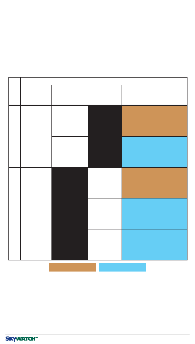
of traffic symbols. Table 3-1 summarizes the criteria necessary for the
SKY497
to display a
TA
. Figures 3-1 through 3-3 show the
TA
zones for various aircraft configurations.
SKY497 Pilot’s Guide
*Having a radio altimeter means having a compatible Arinc 429 radio altimeter wired to the
SKY497
and
providing valid altitude information.
**CPA means Closest Point of Approach.
Sensitivity Level A Sensitivity Level B
TheSKY497Will IssueaTrafficAdvisory…
No.
If Your
Aircraft…
AndYour
Aircraft’s
Altitude Is…
AndYour
Landing
GearIs…
AndAnIntruder
Aircraft IsDetected…
1has a radio
altimeter*
below 2000ft
AGL
withina 0.2nmihorizontal
radiusanda ±600ft relative
altitude
2within15–20sec.of
CPA**
3 above 2000ft
AGL
withina 0.55nmi
horizontalradiusanda
±800ft relative altitude
4within20–30sec.of
CPA**
5does not
have a radio
altimeter*
down withina 0.2nmihorizontal
radiusanda ±600ft relative
altitude
6within15–20sec.of
CPA**
7 up withina 0.55nmi
horizontalradiusanda
±800ft relative altitude
8within20–30sec.of
CPA**
9fixed withina 0.55nmi
horizontalradiusanda
±800ft relative altitude
10 within20–30sec.of
CPA**
Table 3-1. Ten Situations in Which a Traffic Advisory Will Occur
Sensitivity Levels
The
SKY497
uses one of two sensitivity levels, A or B, to determine when to display a
TA
.
Having two sensitivity levels allows the
SKY497
to reduce the number of nuisance
TAs
during takeoff and landing (sensitivity level A), and to maximize the detection of
TAs
during the cruise phase of your flight (sensitivity level B).

3-2 Pilot’s Guide
Principles of Operation
SKY497
Sensitivity Level A
Sensitivity level A consists of two criteria for displaying a
TA
:
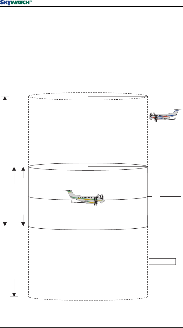
1.The intruder aircraft enters into a cylinder of airspace surrounding your aircraft
defined by a 0.2 nmi horizontal radius and a height of ±600 ft from your aircraft.
(See figures 3-1 and 3-2.)
OR…
2.The intruder aircraft approaches your aircraft on a course that will intercept your
course within 15 or 20 seconds (within 15 seconds for a non-altitude reporting
intruder aircraft; within 20 seconds for an altitude reporting intruder aircraft).
The
SKY497
uses sensitivity level A in the following situations:
1.Your aircraft has a radio altimeter and is below 2,000 ft
AGL
.
2.Your aircraft has no radio altimeter but its retractable landing gear is down. (Sensi-
tivity level A is not used if you have fixed landing gear and no radio altimeter.)
Sensitivity Level B
Sensitivity level B consists of two criteria for displaying a
TA
:
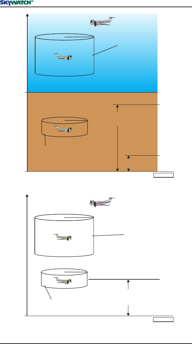
1.The intruder aircraft enters into a cylinder of airspace surrounding your aircraft
defined by a 0.55 nmi horizontal radius and a height of ±800 ft from your aircraft.
(See figures 3-1 through 3-3.)
OR…
2.The intruder aircraft approaches your aircraft on a course that will intercept your
course within 20 or 30 seconds (within 20 seconds for a non-altitude reporting
intruder aircraft; within 30 seconds for an altitude reporting intruder aircraft).
The
SKY497
uses sensitivity level B in the following situations:
1.Your aircraft has a radio altimeter and is above 2,000 ft
AGL
.
2.Your aircraft has no radio altimeter but its retractable landing gear is up.
3.Your aircraft has fixed landing gear and no radio altimeter.
Audio Inhibit, SKY497
This audio inhibit feature prevents the aural part of
TAs
, “traffic traffic,” from being
announced during takeoff and landing in order to minimize pilot distraction. The
corresponding
TA
symbols are still displayed.
The
SKY497
uses this audio inhibit feature in the following situations:
1.Your aircraft has a radio altimeter and you’re below 400 ft
AGL
. (See figure 3-1.)
2.Your aircraft has no radio altimeter but its retractable landing gear is down. (See figure
3-2.) (Audio is not inhibited if you have fixed landing gear and no radio altimeter.)
Pilot’s Guide 3-3
SKY497
Principles of Operation
Figure 3-1. TA Zones If Your Aircraft Has a Radio Altimeter
0.2 nmi
+600 ft
–600 ft
Thisarea or 20 seconds
*
0.55 nmi
+800 ft
–800 ft
This area or 30 seconds
*
*
**15 seconds for non-altitude reporting intruder aircraft
*20 seconds for non-altitude reporting intruder aircraft Not to Scale
Intruder Aircraft
GL
1,700
400
2,000
Feet
Feet
Feet
Ground
Targets
Filtered
TA Zone
Above 2,000 ft
(Sensitivity Level B)
TA Zone
Below 2,000 ft
(Sensitivity Level A) SKY497
Audio Inhibited
0.2 nmi
+600 ft
–600 ft
Thisarea or 20 seconds
*
0.55 nmi
+800 ft
–800 ft
This area or 30 seconds
*
*
**15 seconds for non-altitude reporting intruder aircraft
*20 seconds for non-altitude reporting intruder aircraft Not to Scale
Intruder Aircraft
GL
TA Zone
When Landing Gear is Up
(Sensitivity Level B)
TA Zone
When Landing Gear is Down
(Sensitivity Level A)
SKY497 Audio
Inhibited When
Landing Gear is Down
Figure 3-2. TA Zones If Your Aircraft Has No Radio Altimeter, But Does Have Retractable
Landing Gear
3-4 Pilot’s Guide
Principles of Operation
SKY497
0.55 nmi
+800 ft
–800 ft
Thisareaor 30 seconds*
*20 seconds for non-altitude reporting intruder aircraft Not to Scale
Intruder Aircraft
GL
TA Zone
(Sensitivity Level B)
Figure 3-3. TA Zones If Your Aircraft Has Fixed Landing Gear and No Radio Altimeter
Audio Inhibit, GPWS
If your aircraft has a Ground Proximity Warning System (
GPWS
) interfaced with the
SKY497
and a
GPWS
alarm occurs, the
SKY497
will sense the alarm and delay the aural
“traffic, traffic” component of any
TAs
issued during the
GPWS
alarm until the alarm clears.
TA Symbol Duration
The
TA
symbol remains on screen for a minimum of 8 seconds even if the intruder aircraft
no longer meets the
TA
criteria as long as the
SKY497
continues to track the aircraft.
Ground Target Filtering
Ground target filtering reduces the clutter of visual symbols and aural announcements that
would otherwise be generated for intruder aircraft that are typically present on or near the
ground near airports.
Ground target filtering prevents the issuing of
TAs
and other traffic symbols for intruder
aircraft determined to be below 380 ft
AGL
.
The
SKY497
uses ground target filtering only if your aircraft has a radio altimeter and you’re
below 1,700 ft
AGL
.
Pilot’s Guide 4-1
SKY497
Display Interpretation
Chapter 4
Display Interpretation
Introduction
This chapter explains the meaning of several sample screens. If you have a
STORMSCOPE
WX-1000
installed, refer to the
STORMSCOPE WX-1000
pilot’s guide for interpretation of the
STORMSCOPE
screens. The abbreviation
CPA
used in some of the figures means closest
point of approach.
SKY497 Pilot’s Guide
BLW 2nm
+05
BRT
OFF
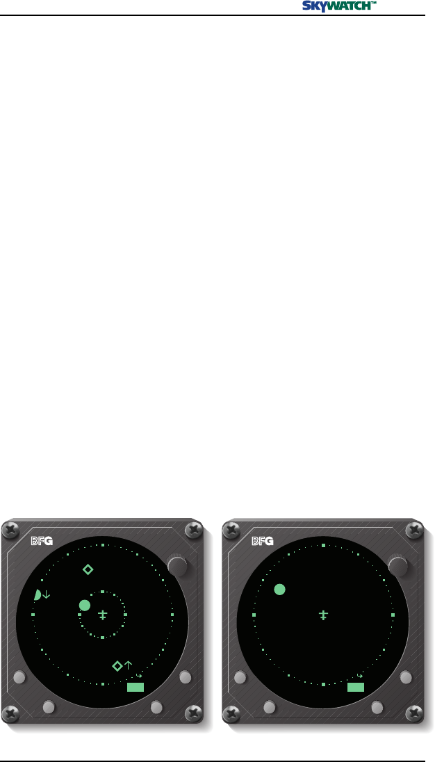
Figure 4-1. Traffic Advisory and Other Traffic
Figure 4-2. Out-of-Range Traffic Advisory
6nm
NRM
+10
-02
BRT
OFF
Other Traffic:
Intruder aircraft
at 11 o’clock,
5 nmi away,
1,000 ft above
you in level flight.
No immediate
threat.
Traffic Advisory:
Intruder aircraft
at 9 o’clock,
2 nmi away,
200 ft below
you, ascending
at a rate greater
than 500 fpm.
CPA within 20 to
30 seconds.
Out-of-Range
Traffic Advisory:
Intruder aircraft
at 9:30, more
than 2 nmi
away, 500 ft
above you,
descending at a
rate greater
than 500 fpm.
CPA within 20 to
30 seconds.
4-2 Pilot’s Guide
Display Interpretation
SKY497
ABV6nm
BRT
OFF
STB
TEST
Failed
SKY497
Error
Barometric Altitude Input
20
BRT
OFF
OPRTEST
Standby
SKY497
BRT
OFF
Figure 4-3. Non-Altitude-Reporting Traffic
Figure 4-4. SKY497 Standby Screen
Figure 4-5. SKY497 Failed Screen
Other Traffic:
Non-altitude-
reporting
intruder aircraft
at 7 o’clock,
5 nmi away.
No immediate
threat.
When in standby,
the SKY497 does
not transmit
interrogations or
track intruder
aircraft. Press
the button labeled
>OPR to begin
tracking intruder
aircraft.
Error 20 indicates
that the baro-
metric input is
missing or invalid.
Once valid baro-
metric input
returns, this
screen goes away
and normal oper-
ation resumes. All
other errors are
unrecoverable, in
which case you
can switch into
optional
STORMSCOPE
mode, or turn off
the SKY497.
This message
occurs any time
the SKY497
detects an error
that prohibits
further operation
of the SKY497 in
SKYWATCH mode
as long as the
message remains
on the screen.
The TEST label
only appears if the
failure occurred
during standby.

Pilot’s Guide 5-1
SKY497
Specifications
Chapter 5
Specifications
SKY497 Pilot’s Guide
Part Number:
805-10800-001
Size:
Not including mounting tray:
7.62 in (19.36 cm) high
3.56 in (9.04 cm) wide
12.52 in (31.90 cm) deep
Weight:
Not including mounting tray:
8.94 lb (4.06 kg)
Including mounting tray:
9.82 lb (4.45 kg)
Tracking Capability:
Up to 30 intruder aircraft (displays only the 8 highest priority aircraft)
Surveillance Range:
Horizontal tracking radius:
11 nmi maximum
Relative altitude tracking range:
±10,000 ft maximum
Display Ranges:
Horizontal display ranges:
2 and 6 nmi
Relative altitude display ranges:
±2,700 ft (normal mode)
+9,000 ft to -2,700 ft (above mode/look up)
+2,700 ft to -9,000 ft (below mode/look down)
Range Accuracy:
±0.05 nmi (typical)
Bearing Accuracy:
5° RMS (typical); 30° peak error
Altitude Accuracy:
±200 ft
Power Input Requirements:
11 to 34 V dc, 70 W (maximum)
Transmitter Power Output:
40 W peak (nominal)
Operating Temperature:
-55 to +70 °C (-67 to +158 °F)
Storage Temperature:
-55 to +85 °C (-67 to +185 °F)
Operating Altitude:
55,000 ft maximum
Cooling:
Conduction and forced air convection (internal fan)
Certification Compliance:
U.S. FAA TSO C147. Contact BFG for the latest foreign country certifications. Refer
to FSAW 98-04 for Flight Standards Service policy concerning follow-on field approvals.
RTCA Compliance:
DO-160C Category F2-BA(NBM)XXXXXXZBABAUAXXXXXX
Table 5-1. Transmitter Receiver Computer (TRC497) Specifications*
*Specifications subject to change without notice.

5-2 Pilot’s Guide
Specifications
SKY497
Table 5-2. WX-1000/SKY497 Display Specifications*
Part Number Definition:
78-8060-5900-8 – black bezel
78-8060-5900-9 – gray bezel
Size: (3ATI)
3.37 in (8.56 cm) high
3.37 in (8.56 cm) wide
8.24 in (20.92 cm) deep
Weight:
2.3 lb (1.0 kg)
Power Input Requirements:
+15 and -15 V dc, 0.7 A maximum
Operating Temperature:
-20 to +55 °C (-4 to +131 °F)
Storage Temperature:
-55 to +70 °C (-67 to +158 °F)
Operating Altitude:
55,000 ft maximum
TSO Compliance:
C110a and C113
RTCA Compliance:
DO-160C F1-CA(NBM)XXXXXXZXXXZUAXXXXXX
*Specifications subject to change without notice.
Part Number:
805-10890-001
Size:
1.30 in (3.25 cm) high
6.25 in (15.88 cm) wide
11.00 in (27.94 cm) deep
Weight:
2.3 lb (1.04 kg)
Speed:
Rated to 600 knots (0.9 Mach) @ 25,000 ft
Frequency:
1,030-1,090 MHz
TSO Category:
C118
Environmental Category:
DO-160C F2-AC(CLM)XSFDFSXXXXXXXL(2A)X
Finish:
Gloss white Skydrol resistant polyurethane paint
Table 5-3. NY164 Directional Antenna Specifications*
*Specifications subject to change without notice.

Pilot’s Guide 6-1
SKY497
Warranty Information
Chapter 6
Warranty Information
Introduction
The
SKY497
is warranted for 2 years from the date of installation (not to exceed 30 months
from the date of shipment from BFGoodrich Avionics Systems, Inc.) subject to the
following limitations.
Warranty Statement
BFGoodrich Avionics Systems, Inc. (hereinafter called
BFGAS
) warrants each item of new
equipment manufactured or sold by
BFGAS
to be free from defects in material and
workmanship, under normal use as intended, for a period of 30 months from date of
shipment by
BFGAS
to an authorized facility, or 24 months from date of installation by an
authorized facility, whichever occurs first. No claim for breach of warranties will be allowed
unless
BFGAS
is notified thereof, in writing, within thirty (30) days after the material or
workmanship defect is found.
The obligation of
BFGAS
shall be limited to replacing or repairing at its factory the
equipment found defective under terms of this warranty certificate; providing that such
equipment is returned in an approved shipping container, transportation charges prepaid,
to
BFGAS
, Grand Rapids, Michigan, or such other location as
BFGAS
may authorize.
BFGAS
reserves the right to have necessary repairs performed by an authorized agency.
This warranty shall not apply to any unit or part thereof which has not been installed or
maintained in accordance with
BFGAS
instructions, or has been repaired or altered in any
way so as to adversely affect its performance or reliability, or which has been subjected to
misuse, negligence or accident.
This warranty is exclusive and is accepted by buyer in lieu of all other guaranties or
warranties express or implied, including without limitation the implied warranties of
merchantability and fitness for a particular purpose. Buyer agrees that in no event will
BFGAS
liability for all losses from any cause, whether based in contract, negligence, strict
liability, other tort or otherwise, exceed buyer’s net purchase price, nor will
BFGAS
be liable
for any special, incidental, consequential, or exemplary damages.
BFGAS
reserves the right to make changes in design or additions to or improvements in its
equipment without the obligation to install such additions or improvement in equipment
theretofore manufactured.
A Subsidiary of The BFGoodrich Company
SKY497 Pilot’s Guide

6-2 Pilot’s Guide
Warranty Information
SKY497
Related Policies and Procedures
a.If the original registered owner of a
SKY497
sells the aircraft in which the
SKY497
is
installed during the warranty period, the remaining warranty may be transferred.
Written notification of the transaction must be submitted by the initial recipient of
the warranty to:
ATTENTION: WARRANTY ADMINISTRATOR
BFGoodrich Avionics Systems, Inc.
5353 52nd Street, S.E.
b.Equipment must be installed by a BFG Avionics Systems, Inc. authorized dealer or
installer. Installation of equipment by facilities not specifically authorized will void the
equipment warranty.
c.Notice of a claimed product defect must be given to BFG Avionics Systems, Inc. or a
designated BFG Avionics Systems, Inc. service agency within the specified warranty
period.
d.A product which is defective in workmanship and/or material shall be returned to
BFG Avionics Systems, Inc. via any authorized dealer with transportation charges
prepaid. After correction of such defects, the equipment will be returned to the dealer,
transportation prepaid by BFG Avionics Systems, Inc. via surface transportation.
Any other means of transportation must be paid by the customer.
The risk of loss or damage to all products in transit shall be assumed by the party
initiating the transportation of such products. All items repaired or replaced hereun-
der shall be warranted for the unexpired portion of the original warranty.
e.BFG Avionics Systems, Inc. is in no way obligated or responsible for supporting or
participating in the costs of the installation warranty. The entire responsibility lies
with the BFG Avionics Systems, Inc. authorized dealer making the installation. BFG
Avionics Systems, Inc. is only responsible for the product warranties outlined in the
warranty statement.
f.BFG Avionics Systems, Inc. cannot authorize warranty credit for troubleshooting of
other systems in the aircraft in order to reduce noise interference with the
SKY497
.
Grand Rapids, MI 49588-0873 U.S.A.
Record of Important Information
Dealer Information
Name ________________________________________________________
Address ______________________________________________________
City, State, Zip _________________________________________________
Telephone ____________________________________________________
Equipment Information
Date of Purchase _______________________________________________
Installation Date from FAA Form 337 ______________________________
TRC
Model Number ______________________________________________
Part Number ________________________________________________
Serial Number _______________________________________________
Firmware Version _____________________________________________
Display
Model Number ______________________________________________
Part Number ________________________________________________
Serial Number _______________________________________________
Directional Antenna
Model Number ______________________________________________
Part Number ________________________________________________
Serial Number _______________________________________________
Note
To ensure that a new or repaired SKY497 meets the TSO, gets
foreign government approval, and meets BFGoodrich Avionics
Systems, Inc. performance standards, your SKY497 must be in-
stalled and tested by a BFG-authorized SKY497 dealer.

009-10801-001 (Rev. B, 6/6/00)
BFGoodrich Avionics Systems, Inc.
5353 52nd Street, S.E.
P.O. Box 873
Grand Rapids, MI 49588-0873 USA
(800)253-9525
www.bfgavionics.com