L 3 Communications Avionics Systems TRC497 SkyWatch Traffic Advisory System User Manual COVER
L-3 Communications, Avionics Systems SkyWatch Traffic Advisory System COVER
Contents
- 1. Install Manual part 1 of 3
- 2. Install Manual part 2 of 3
- 3. Install Manual part 3 of 3
- 4. Pilots Guide part 1 of 2
- 5. Pilots guide part 2 of 2
Install Manual part 2 of 3
4. WHEN INTERFACING TO AN ALTERNATE DISPLAY THE SERVICE MENU CANNOT BE ACCESSED,
THEREFORE A TERMINAL DEVICE (I.e., LAPTOP) MUST BE USED FOR SETUP AND CHECKOUT
OF TRC497.
15. WHEN INTERFACING TO AN ALTERNATE DISPLAY THE SOFTKEY INPUTS MUST BE CONNECTED PER
DISPLAY MANUFACTURER INSTRUCTIONS.
SKY497
Installation Manual
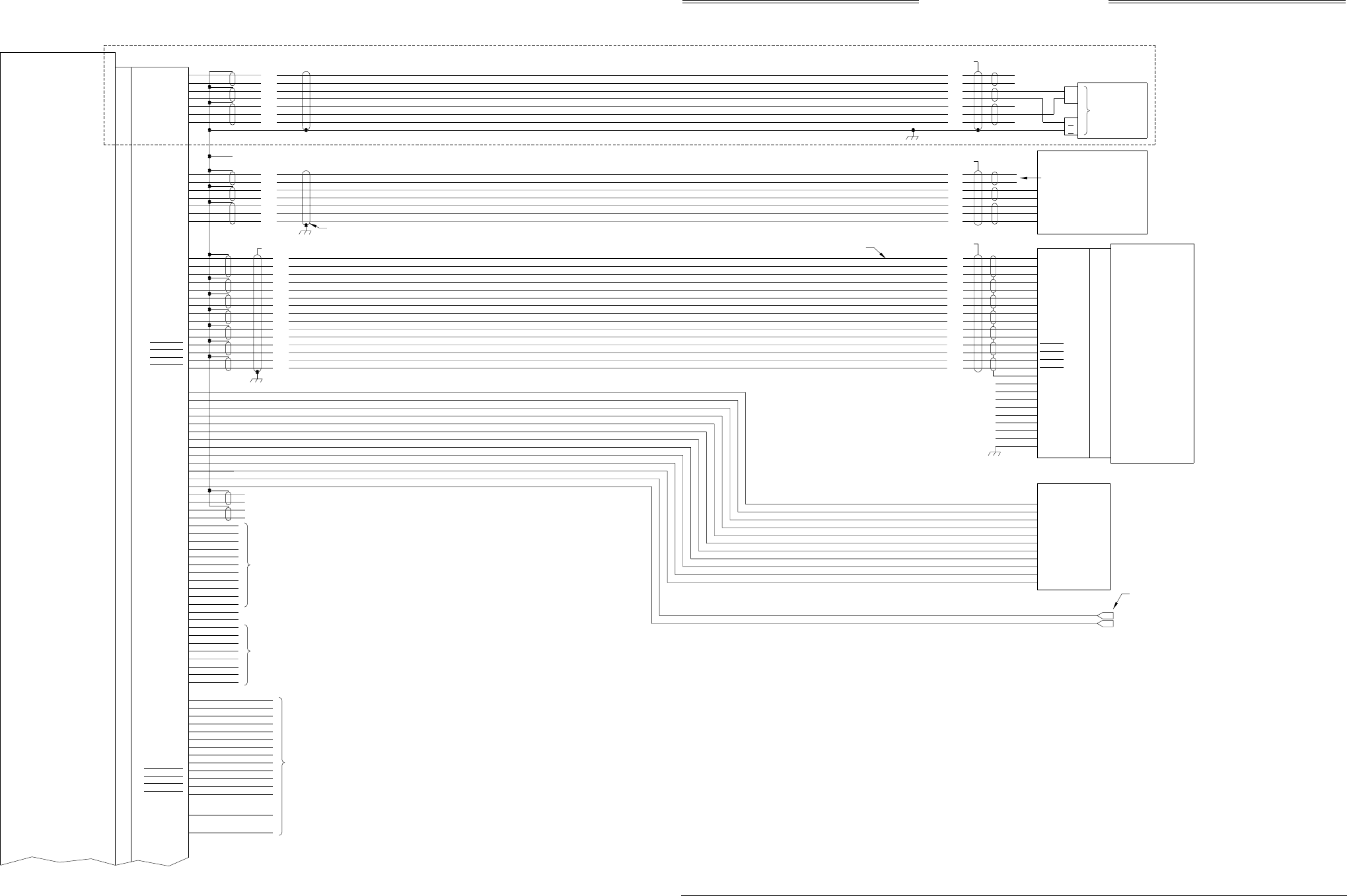
Figure 2-2. Interconnect Wiring Without WX-1000
(Sheet 1 of 2)
2-3 (page 2-4 blank)
Rev. C
HSYNCHI
HSYNCLO
VSYNCHI
VSYNCLO
VIDEOHI
VIDEOLO
PWRSWHI
PWRSWLO
DSPGND
-15
+15
SHIELD
NOTES:
1. ALL WIRES TO BE 22 AWG EXCEPT WHERE NOTED.
2. TP - USE TWISTED SHIELDED PAIR CABLE. TERMINATE SHIELD TO AIRFRAME
5. A RADIO ALTIMETER, AIRDATA COMPUTER, OR OTHER ARINC 429 OUTPUT
DEVICE MAY REPLACE ANALOG SENSORS FOR MAGNETIC HEADING, RADIO
ALTITUDE, OR BAROMETRIC ALTITUDE.
SQUAT SWITCH
LANDING GEAR POSITION
ALTITUDE
A1
A2
A4
B1
B2
B4
C1
C2
C4
D4
2
20
16
15
17
11
24
25
19
13
14
12
18
23
22
7
8
10
9
5
6
P101 J101
SEE NOTE #6
SEE NOTE #15
SEE NOTE #6
LOW
HIGH
Z
Y
X}}26 VAC REFERENCE
HEADING
DIRECTIONAL GYRO COMPASS
TRANSMITTER
RECEIVER
COMPUTER
UNIT
HDG_FLG+
HDG_FLG-
SYNC_X
SYNC_Y
SYNC_Z
SYNC_HI
SYNC_LO
52
53
66
65
64
55
54
J1 P1
100
DPWR+15_OUT
DPWR-15_OUT
7
DSPLY_GND
6
HSYNC_OUT_HI
14
HSYNC_OUT_LO
49
VSYNC_OUT_HI
48
VSYNC_OUT_LO
63
VIDEO_OUT_HI
62
VIDEO_OUT_LO
38
PWR_SW_HI
37
PWR_SW_LO
11
TOP_BOT
3
NY164_NY156 99
FIX_ROTOR 98
DR_RX+ 9
DR_RX- 8
DR_TX+ 2
DR_TX- 1
ALT_A1 40
ALT_A2 41
ALT_A4 50
ALT_B1 51
ALT_B2 56
ALT_B4 57
ALT_C1 58
ALT_C2 59
ALT_C4 71
ALT_D4 72
SQUAT 88
GEAR 87
10
39
93
SEE TABLE "A"
TP
TP
TP
TP
TP
TP
TP
ALT_COMMON
TRC497
WX-1000
3. THE SUM CABLE WILL HAVE A BLUE BAND AT EACH END. THE DIFFERENCE CABLE
WILL HAVE A RED BAND AT EACH END.
6. TIE THE OUTER SHIELD TO THE CONNECTOR BACKSHELL. CONNECTOR BACKSHELL IS CHASSIS GROUND.
7. FOR FUTURE EXPANSION. LEAVE UNCONNECTED.
HEADING INPUT CABLE
DISPLAY CABLE
SEE NOTE #6
8. DELETED
WHT
ORN
BLU
WHT
BLU
WHT
BLU
BLU
WHT
BLU
WHT
BLU
WHT
BLU
WHT
BLU
ORN
WHT
BLU
ORN
RED
GRN
WHT
BLU
WHT
BLU
WHT
BLU
WHT
BLU
BLU
ORN
WHT
BLU
WHT
BLU
ORN
WHT
BLU
ORN
RED
GRN
WHT
BLU
WHT WHT
SEE NOTE #12
BLU
WHT ORN
ORN
TP BLU
WHT
SEE NOTE #6
SFTKEY1
SFTKEY2
SFTKEY4
SFTKEY3
N/C
+15V
-15V
SPARE_1
SPARE_2
SPARE_3
GROUND AT SENSOR (OR POWER SOURCE).
9. USE AUDIO_H FOR 600 OHM AUDIO SYSTEMS. USE AUDIO_L FOR 150 OHM AUDIO
10. DO NOT INSTALL EXTERNAL ISOLATION DIODES.
SEE NOTE 10
SEE NOTE 10
SEE NOTE 10
DISPLAY
STP_CONFIG4
STP_CONFIG5
STP_CONFIG6 95
96
97
STP_CONFIG8
STP_CONFIG7 86
94
ALT_COMN 81
SFTKEY4_IN 82
SFTKEY3_IN 83
SFTKEY2_IN 84
SFTKEY1_IN 85
68
67
HEADING_FLG
DR_ALT422
77
70
69
STEPPER_IN
SYNCHRO_IN
ALT_DISP4
SEE NOTE #7
78
ALT_DISP3
79
ALT_DISP2
ALT_DISP1 80
BLK
YEL
BLU
WHT
BLU
WHT
WHT
BLU
WHT
BLU
YEL
BLKTP
TP
4
3
21 CHASSIS
GND
1
SYSTEMS.
11. SPARE PINS 16, 17, 18, 19, 20, 25, 26, 27, 28, 29, AND 30
ARE NOT SHOWN AND NOT USED.
HEADING VALID
12. HEADING FLAG CONNECTIONS NEED TO BE CONFIGURED PROPERLY FOR YOUR
AIRCRAFT.
DIGITIZER
P/O P/O
WHT
BLU
TP ORN ORN
WHT
BLU
BLU
WHT
WHT
ORN
BLU
WHT
BLU
BLU
WHT
BLU
WHT
BLU
ORN
WHT
GROUND
AIRFRAME
TP
54
55
64
65
66
53
52
SYNC_LO
SYNC_HI
SYNC_Z
SYNC_Y
SYNC_X
HDG_FLG-
HDG_FLG+
KI-525 INDICATOR
J
V
SEE NOTE #6
H
A
FLAG-
FLAG+
NC
NC
P1
P2
TOP
BOT
STEPPER
HEADING
ALTERNATE
INPUT
SEE NOTE #13
HDG FLAG +
UNREG +15
DRIVE MOTOR 1
DRIVE MOTOR 3
HDG FLAG -
13. STEPPER HEADING INPUT MAY BE USED IN PLACE OF SYNCHRO HEADING.
14. DELETED
13
12
CONFIG_GND
CONFIG_GND
SEE NOTE #6
VIDEO_IN_LO 35
SW_RET
CWS_SS
SFTKEY4_OUT
SFTKEY3_OUT
SFTKEY2_OUT
SFTKEY1_OUT
4
31
73
74
75
76
DPWR+15_IN
DPWR-15_IN
DSPLY_GND
HSYNC_IN_HI
HSYNC_IN_LO
VSYNC_IN_HI
VSYNC_IN_LO
VIDEO_IN_HI
46
60
36
61
15
47
24
5
N/C
N/C
N/C
N/C
N/C
N/C
N/C
N/C
N/C
GND
GND
GND
GND
SEE NOTE #12
SKY497
Installation Manual
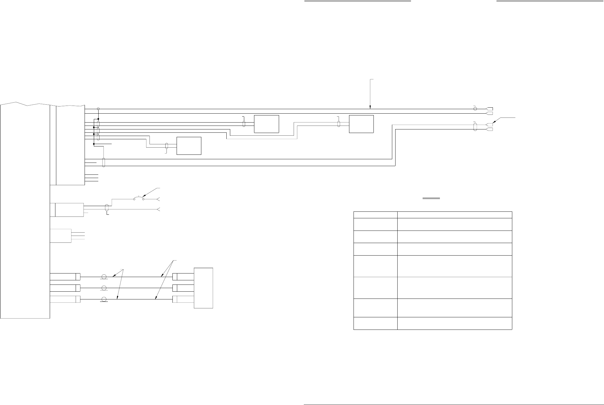
Figure 2-2. Interconnect Wiring Without WX-1000
(Sheet 2 of 2)
2-5 (page 2-6 blank)
Rev. C
F3
J11
J7
TYPE TNC
DIAG_GND
DIAG_RX
DIAG_TX
5
2
3}
TRANSMITTER
RECEIVER
COMPUTER
UNIT
J8 P8
+28V
SPARE
+28V_RET
AIRCRAFT POWER
A
B
C
16 AWG
CONNECTOR
TRC497
J10
DIFFERENCE
J9
SUM
CONNECTOR
TYPE TNC
CONNECTOR
TYPE BNC
TEST ONLY
SUM
DIFFERENCE
BLUE BAND
RED BAND
DIRECTIONAL
ANTENNA
SEE NOTE # 3
TNC
BNC
TNC
P9
P10
P11 P1
P2
P3
AIRCRAFT POWER RETURN
SEE NOTE #2
BIT_PROBE BIT_PROBE
SEE NOTE #3
16 AWG
(11 - 34VDC)
NY164/NY156
TEST ONLY
}
23
22
21
IOP_SERIAL_TX
IOP_SERIAL_GND
IOP_SERIAL_RX
NOTE: FOR 14V USE 7.5 A
FOR 28V USE 5.0 A
SUPPRESSION I/O
AUDIO COMMON
SEE NOTE #6
AUDIO HIGH
SEE NOTE #2
SEE NOTE #6
TP
TP
TP
32
33
34
42
43
44
45
89
GPWS
ARINC-429 TX 1B
ARINC-429 TX 1A
ARINC-429 RX 2B
ARINC-429 RX 2A
ARINC-429 RX 1B
ARINC-429 RX 1A
SUP_BUS
SEE NOTE #2
ARINC 429
DEVICE
(SEE NOTE #5)(SEE NOTE #5)
DEVICE
ARINC 429
GPWSFLAG
TP
90
AUDIO_C
91
AUDIO_L
92
AUDIO_H
J1 P1
P/O P/O
FUNCTION
AIRFRAME
FIXED WING
ROTOR CRAFT
CONFIGURATION JUMPER
P1-98
(OPEN)
(JUMPER TO CONFIG GROUND)
1
0
ANTENNA
NY-164
NY-156
P1-99
1
0
(OPEN)
(JUMPER TO CONFIG GROUND)
ANTENNA POSITION
TOP
BOTTOM
ARINC-429 ALTERNATE DISPLAY
NONE
ARINC735 TYPE1
P1-100
1
0
(OPEN)
(JUMPER TO CONFIG GROUND)
P1-77
1
1
(1 = OPEN)
(O = JUMPER TO CONFIG GROUND)
P1-78
1
1
P1-79
1
1
P1-80
1
0
HEADING INPUT SOURCE
NONE
SYNCHRO
P1-69 P1-70
1
01
1 (1 = OPEN)
(O = JUMPER TO CONFIG GROUND)
STEPPER 0 1
ARINC429 BUS 0 0
(JUMPER TO CONFIG GROUND)
(OPEN)
0
1
P1-67
ALTERNATE
DATA RECORDER
RS422 INTERFACE
*
(CONFIG GROUND IS AVAILABLE AT P1-12 AND P1-13)
TABLE "A"
*FUTURE OPTION
HDG_FLG+ (P1-53) INDICATES VALID HEADING.)
(1 = OPEN - IF LOW LEVEL INPUT ON HDG_FLG+ (P1-53)
HEADING FLAG SENSE
LOW
P1-68
1
INDICATES VALID HEADING OR NO VALID HEADING INPUT IS
AVAILABLE OR WHEN ARINC-429 INPUT IS HEADING SOURCE.)
HIGH 0 (O = JUMPER TO CONFIG GROUND - IF HIGH LEVEL INPUT ON
(RED)
(BLUE)
CAUTION: THE AIRCRAFT TRANSPONDER MUST
HAVE SHIELDED SUPPRESSION CIRCUITRY
TO ENSURE THAT SKYWATCH DOES NOT
DISPLAY ITSELF AS A TARGET (TA).
INSTALLATION CONFIGURATION
(OPTIONAL)
ALTERNATE
DISPLAY
(SEE NOTE #4)
SEE NOTE #2
SEE NOTE #6
SEE NOTE #9
SKY497
Installation Manual
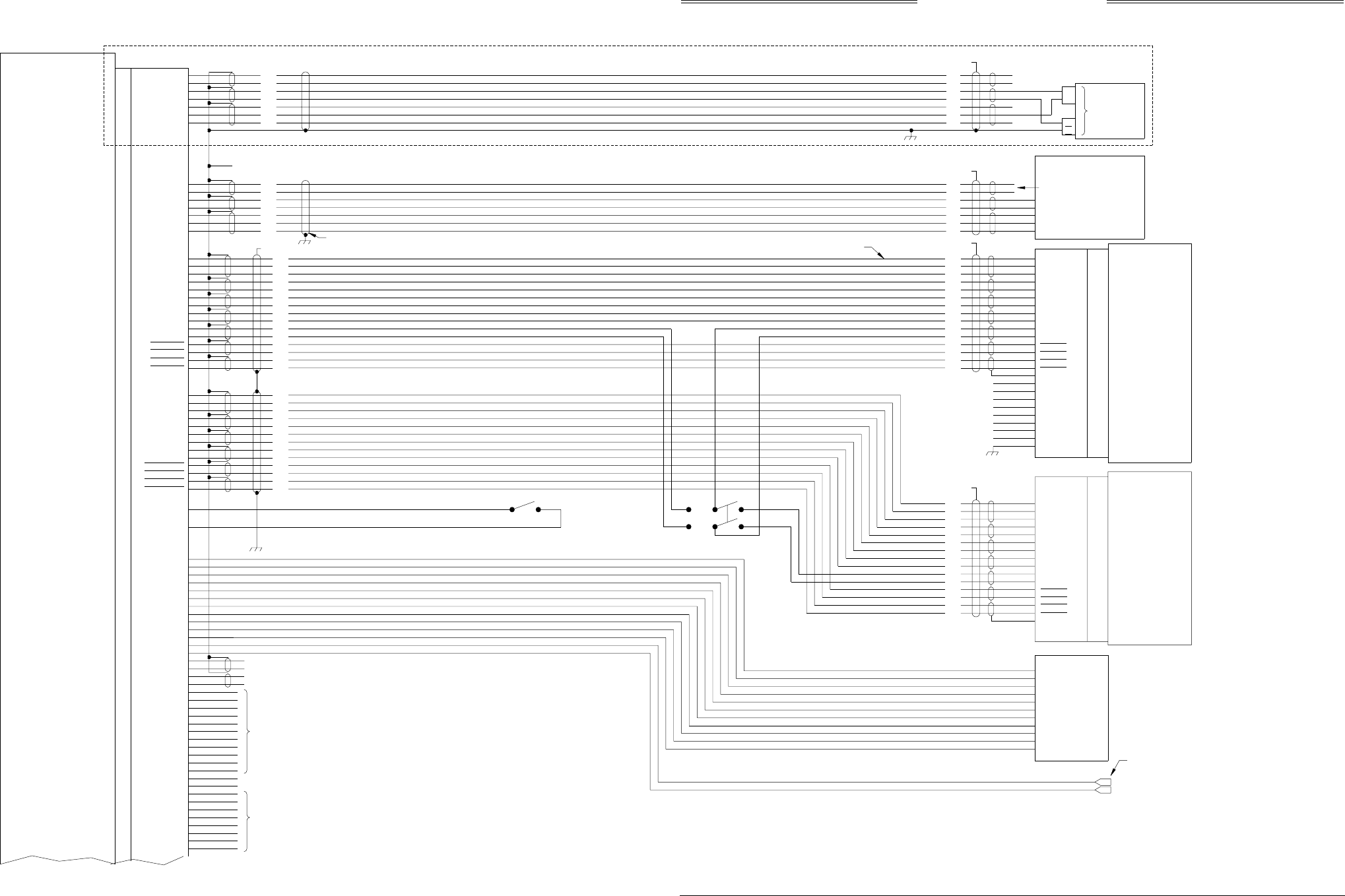
Figure 2-3. Interconnect Wiring With WX-1000
(Sheet 1 of 2)
2-7 (page 2-8 blank)
Rev. C
HSYNCHI
HSYNCLO
VSYNCHI
VSYNCLO
VIDEOHI
VIDEOLO
PWRSWHI
PWRSWLO
DSPGND
-15
+15
SHIELD
NOTES:
1. ALL WIRES TO BE 22 AWG EXCEPT WHERE NOTED.
2. TP - USE TWISTED SHIELDED PAIR CABLE. TERMINATE SHIELD TO AIRFRAME
4. FUTURE OPTION.
5. A RADIO ALTIMETER, AIRDATA COMPUTER, OR OTHER ARINC 429 OUTPUT
DEVICE MAY REPLACE ANALOG SENSORS FOR MAGNETIC HEADING, RADIO
ALTITUDE, OR BAROMETRIC ALTITUDE.
SQUAT SWITCH
LANDING GEAR POSITION
ALTITUDE
A1
A2
A4
B1
B2
B4
C1
C2
C4
D4
2
20
16
15
17
11
24
25
19
13
14
12
18
23
22
7
8
10
9
5
6
P101 J101
SEE NOTE #6
SEE NOTE #6
LOW
HIGH
Z
Y
X}
}26 VAC REFERENCE
HEADING
DIRECTIONAL GYRO COMPASS
TRANSMITTER
RECEIVER
COMPUTER
UNIT
HDG_FLG+
HDG_FLG-
SYNC_X
SYNC_Y
SYNC_Z
SYNC_HI
SYNC_LO
52
53
66
65
64
55
54
P1
100
DPWR+15_OUT
DPWR-15_OUT
7
DSPLY_GND
6
14
49
48
63
62
38
37
11
TOP_BOT
3
NY164_NY156 99
FIX_ROTOR 98
DR_RX+ 9
DR_RX- 8
DR_TX+ 2
DR_TX- 1
ALT_A1 40
ALT_A2 41
ALT_A4 50
ALT_B1 51
ALT_B2 56
ALT_B4 57
ALT_C1 58
ALT_C2 59
ALT_C4 71
ALT_D4 72
SQUAT 88
GEAR 87
10
39
93
SEE TABLE "A"
TP
TP
TP
TP
TP
TP
TP
ALT_COMMON
TRC497
WX-1000
3. THE SUM CABLE WILL HAVE A BLUE BAND AT EACH END. THE DIFFERENCE CABLE
WILL HAVE A RED BAND AT EACH END.
6. TIE THE OUTER SHIELD TO THE CONNECTOR BACKSHELL. CONNECTOR BACKSHELL
7. FOR FUTURE EXPANSION. LEAVE UNCONNECTED.
HEADING INPUT CABLE
DISPLAY CABLE
SEE NOTE #6
WHT
ORN
BLU
WHT
BLU
WHT
BLU
BLU
WHT
BLU
WHT
BLU
WHT
BLU
WHT
BLU
ORN
WHT
BLU
ORN
RED
GRN
WHT
BLU
WHT
BLU
WHT
BLU
WHT
BLU
BLU
ORN
WHT
BLU
WHT
BLU
ORN
WHT
BLU
ORN
RED
GRN
WHT
BLU
WHT WHT
SEE NOTE #12
BLU
WHT ORN
ORN
TP BLU
WHT
SEE NOTE #6
SFTKEY1
SFTKEY2
SFTKEY4
SFTKEY3
SPARE_1
SPARE_2
SPARE_3
GROUND AT SENSOR (OR POWER SOURCE).
SEE NOTE 10
SEE NOTE 10
SEE NOTE 10
DISPLAY
STP_CONFIG4
STP_CONFIG5
STP_CONFIG6 95
96
97
STP_CONFIG8
STP_CONFIG7 86
94
ALT_COMN 81
82
83
84
85
68
67
HEADING_FLG
DR_ALT422
77
70
69
STEPPER_IN
SYNCHRO_IN
ALT_DISP4
SEE NOTE #7
78
ALT_DISP3
79
ALT_DISP2
ALT_DISP1 80
BLK
YEL
BLU
WHT
BLU
WHT
WHT
BLU
WHT
BLU
YEL
BLKTP
TP
4
3
21 CHASSIS
1
WX-1000
PROCESSOR
TP
TP BLK
YEL
76
SFTKEY1_OUT 75
SFTKEY2_OUT 74
SFTKEY3_OUT 73
SFTKEY4_OUT
WHT
RED
ORN
BLUTP
TP
TP
35
36
VIDEO_IN_LO
60
VIDEO_IN_HI
61
VSYNC_IN_LO
46
VSYNC_IN_HI
47
HSYNC_IN_LO
15
HSYNC_IN_HI
5
DSPLY_GND
24
DPWR-15_IN
DPWR+15_IN
BLU
WHT
BLU
WHT
WHT
ORN
BLU
WHT
BLU
WHT
BLU
WHT
BLU
WHT
BLU
WHT
BLU
WHT
ORN
BLU
BLU
WHT
BLU
WHT
BLU
WHT
BLU
WHT
YEL
BLK
SFTKEY3
SFTKEY4
SFTKEY2
SFTKEY1
WHT
GRN
RED
ORN
BLU
6
23
40
7
39
22
21
20
38
26
36
9
3
43
44
+15
-15
DSPGND
PWRSWLO
PWRSWHI
VIDEOLO
VIDEOHI
VSYNCLO
VSYNCHI
HSYNCLO
HSYNCHI
5SHIELD
31
CWS_SS SW1
P301 J301
HEADING VALID
DIGITIZER
4
SW_RET
SW2
P/O
WHT
BLU
TP ORN ORN
WHT
BLU
BLU
WHT
WHT
ORN
BLU
WHT
BLU
BLU
WHT
BLU
WHT
BLU
ORN
WHT
GROUND
AIRFRAME
TP
54
55
64
65
66
53
52
SYNC_LO
SYNC_HI
SYNC_Z
SYNC_Y
SYNC_X
HDG_FLG-
HDG_FLG+
KI-525 INDICATOR
J
V
SEE NOTE #6
H
A
FLAG-
FLAG+
NC
NC
P1
P2
TOP
BOT
STEPPER
HEADING
ALTERNATE
INPUT
SEE NOTE #13
HDG FLAG +
UNREG +15
DRIVE MOTOR 1
DRIVE MOTOR 3
HDG FLAG -
13
12
CONFIG_GND
CONFIG_GND
OVER-RIDE NORMAL
STORMSCOPE
SKYWATCH
SEE NOTE #6
PWR_SW_LO
PWR_SW_HI
VIDEO_OUT_LO
VIDEO_OUT_HI
VSYNC_OUT_LO
VSYNC_OUT_HI
HSYNC_OUT_LO
HSYNC_OUT_HI
SFTKEY4_IN
SFTKEY3_IN
SFTKEY2_IN
SFTKEY1_IN
J1
P/O
AND NOTE #8
SEE NOTE #6
AND NOTE #8
GND
GND
+15V
GND
-15V
GND
N/C
GND
N/C
N/C
N/C
N/C
N/C
N/C
N/C
N/C
SEE NOTE 14
8. IF THE SKYWATCH IS BEING INSTALLED TO AN EXISTING WX-1000 SYSTEM, THE
CABLE GROUND AT THE WX-1000 DISPLAY AND THE WX-1000 PROCESSOR MUST
BE CHANGED FROM AS SHOWN IN THE WX-1000 MANUAL TO BE AS SHOWN HERE.
9. USE AUDIO_H FOR 600 OHM AUDIO SYSTEMS. USE AUDIO_L FOR 150 OHM AUDIO
SYSTEMS.
10. DO NOT INSTALL EXTERNAL ISOLATION DIODES.
11. SPARE PINS 16, 17, 18, 19, 20, 25, 26, 27, 28, 29, AND 30
ARE NOT SHOWN AND NOT USED.
12. HEADING FLAG CONNECTIONS NEED TO BE CONFIGURED PROPERLY FOR YOUR
AIRCRAFT.
13. STEPPER HEADING INPUT MAY BE USED IN PLACE OF SYNCHRO HEADING.
14. INSTALLATION INSTRUCTIONS FOR THE WX-1000 ARE DETAILED IN THE
WX-1000 INSTALLATION MANUAL.
SEE NOTE #12
IS CHASSIS GROUND.
SKY497
Installation Manual
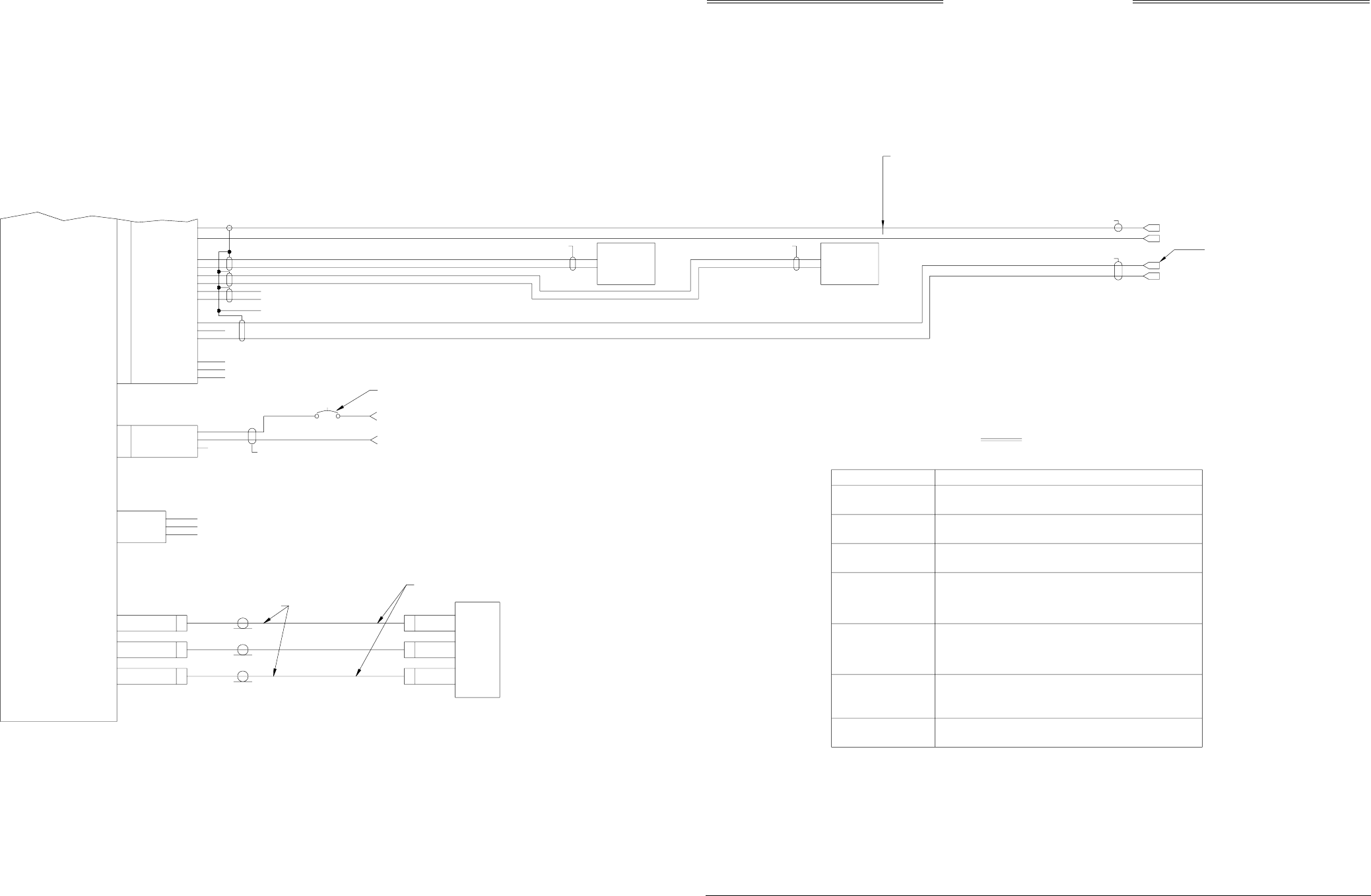
Figure 2-3. Interconnect Wiring With WX-1000
(Sheet 2 of 2)
2-9 (page 2-10 blank)
Rev. C
F3
J11
J7
TYPE TNC
DIAG_GND
DIAG_RX
DIAG_TX
5
2
3}
TRANSMITTER
RECEIVER
COMPUTER
UNIT
P8
+28V
SPARE
+28V_RET
AIRCRAFT POWER
A
B
C
16 AWG
CONNECTOR
TRC497
J10
DIFFERENCE
J9
SUM
CONNECTOR
TYPE TNC
CONNECTOR
TYPE BNC
TEST ONLY
SUM
DIFFERENCE
BLUE BAND
RED BAND
DIRECTIONAL
ANTENNA
SEE NOTE # 3
TNC
BNC
TNC
P9
P10
P11 P1
P2
P3
AIRCRAFT POWER RETURN
SEE NOTE #2
BIT_PROBE BIT_PROBE
SEE NOTE #3
16 AWG
(11 - 34VDC)
NY164/NY156
TEST ONLY
}
23
22
21
IOP_SERIAL_TX
IOP_SERIAL_GND
IOP_SERIAL_RX
NOTE: FOR 14V USE 7.5 A
FOR 28V USE 5.0 A
SEE NOTE #4
SUPPRESSION I/O
AUDIO COMMON
SEE NOTE #6
AUDIO HIGH
SEE NOTE #2
SEE NOTE #6
TP
TP
TP
32
33
34
42
43
44
45
89
GPWS
SUP_BUS
SEE NOTE #2
ARINC 429
DEVICE
(SEE NOTE #5)(SEE NOTE #5)
DEVICE
ARINC 429
GPWSFLAG
TP
90
AUDIO_C
91
AUDIO_L
92
AUDIO_H
P1
P/O
FUNCTION
AIRFRAME
FIXED WING
ROTOR CRAFT
CONFIGURATION JUMPER
P1-98
(OPEN)
(JUMPER TO CONFIG GROUND)
1
0
ANTENNA
NY-164
NY-156
P1-99
1
0
(OPEN)
(JUMPER TO CONFIG GROUND)
ANTENNA POSITION
TOP
BOTTOM
ARINC-429 ALTERNATE DISPLAY
NONE
P1-100
1
0
(OPEN)
(JUMPER TO CONFIG GROUND)
P1-77
1 (1 = OPEN)
(O = JUMPER TO CONFIG GROUND)
P1-78
1
P1-79
1
P1-80
1
HEADING INPUT SOURCE
NONE
SYNCHRO
P1-69 P1-70
1
01
1(1 = OPEN)
(O = JUMPER TO CONFIG GROUND)
STEPPER 0 1
ARINC429 BUS 0 0
(JUMPER TO CONFIG GROUND)
(OPEN)
0
1
P1-67
ALTERNATE
DATA RECORDER
RS422 INTERFACE
*
TABLE "A"
FUTURE OPTION
*
HDG_FLG+ (P1-53) INDICATES VALID HEADING.)
(1 = OPEN - IF LOW LEVEL INPUT ON HDG_FLG+ (P1-53)
HEADING FLAG SENSE
LOW
P1-68
1
INDICATES VALID HEADING OR NO VALID HEADING INPUT IS
AVAILABLE OR WHEN ARINC-429 INPUT IS HEADING SOURCE.)
HIGH 0 (O = JUMPER TO CONFIG GROUND - IF HIGH LEVEL INPUT ON
(RED)
(BLUE)
(CONFIG GROUND IS AVAILABLE AT P1-12 AND P1-13)
INSTALLATION CONFIGURATION
SHIELDED SUPPRESSION CIRCUITRY TO ENSURE
THAT SKYWATCH DOES NOT DISPLAY ITSELF AS
ATARGET (TA).
THE AIRCRAFT TRANSPONDER MUST HAVECAUTION:
J8
J1
P/O
ARINC-429 RX 1A
ARINC-429 RX 1B
ARINC-429 RX 2A
ARINC-429 RX 2B
ARINC-429 TX 1A
ARINC-429 TX 1B
SEE NOTE #6
SEE NOTE #9

SKY497
Installation Manual
2-11
Rev. C
2.5 DISPLAY LOCATION
The display should be mounted in a location easily accessible and clearly visible to the pilot. In selecting a
location, consider the following:
Magnetic Effect Where possible to avoid it, the display should not be mounted within
3 inches (8 cm) of an electric turn and bank indicator, as the magnetic
effect of the turn and bank motor may affect the display presentation. (a
common symptom of magnetic interference is a wobbling or vibrating
display raster.)
NOTE
If it is necessary to mount the display unit next to a device that may affect
the CRT display, magnetic shielding material can be placed around the
display unit. Shielding material is available from BFG Avionics Systems.
Specify P/N 78-8060-5882-8 when ordering.
Panel Depth Adequate depth must be available behind the instrument panel to allow for
the display, the display connector, and excess display cable. Remember, a
service loop is necessary to allow access to the display connector when
removing the display or inserting it into the instrument panel.
Cooling While the display has no special cooling requirements, it should be
mounted to permit adequate ventilation.
Viewing Angle The viewing angle for the CRT display is not a critical factor. The most
favorable mounting position would be near eye level and no more than
arms length from the principle user of the instrument.
2.6 CABLE REQUIREMENTS AND FABRICATION
NOTE
All wiring must be in accordance with industry accepted methods,
techniques and practices.
The installer will supply and fabricate all system cables. Appendix A defines the electrical characteristics
of all input and output signals and identifies the cable requirements for each signal. Refer to figure 2-2
(without WX-1000) or 2-3 (with WX-1000) for interconnect wiring information. Required connectors and
contact pins are supplied in the installation kits.
The length and routing of the external cables must be carefully studied and planned before attempting
installation of the equipment. Observe the following precautions:
• Note the signal characteristics of flag lines and discrete signal inputs; an external relay may be
required to provide proper polarity or "sense" of the signals.
• All cable routing should be kept as short and direct as possible.
• Avoid sharp bends (do not exceed the minimum bend radius detailed in table 2-1).
• Avoid routing the cables too close to aircraft control cables.
• Avoid routing cable near the ADF, comm radio, or transponder antenna cables (allow at least a 12
inch separation).
• Avoid routing cable near power sources (e.g., 400 Hertz generators, trim motors, etc.) and near
power for fluorescent lighting.
• To limit the possibility of wire chafing, it is recommended that heat shrink sleeving be installed
over the wire bundle between the shield termination’s (inside the connector backshell) and the
connector cable clamp.
• Observe all wiring notes on interconnect wiring diagram.

SKY497
Installation Manual
2-12
Rev. C
After fabricating the cables and before installing the equipment, use the interconnect diagram to verify
continuity between each pin and its opposite end termination. Check resistance to ground between each
connector pin. When a path to ground is detected, verify its validity.
2.6.1 Antenna Cables
NOTES
1. Use of any cable not meeting BFG Avionics Systems specifications voids all
system warranties.
2. If you fabricate your own cables, you must verify that the attenuation and
VSWR does not exceed the specified values.
3. To add strain relief and alleviate stress caused by aircraft vibration, place 4-
6 inches of heat shrink tubing over each antenna connector and cable.
The directional antenna requires three cable assemblies; sum (Sigma Port), bit probe (Probe Port) and
difference (Delta Port). Cable attenuation for the sum and difference ports must not exceed 2.5 dB. Table
2-1 identifies U. S. vendors who sell approved cables by the foot. Table 2-2 provides a cable to connector
cross reference. RG142B or equivalent may be used for the bit probe cable. Attenuation for the bit probe
cable must not exceed 6 dB. VSWR, on cables attached to the sum, bit probe, and difference ports, must not
exceed 1.5:1.
Table 2-1. Directional Antenna SIGMA and DELTA Port Cable Vendors
Electrical & Mechanical Technologies (EMTEQ)
1-888-879-6170
262-679-6170
FAX 262-679-6175
Part Number
Attenuation
(dB/100 ft 1.0 gHz)
Weight (lb)
(per 100 ft)
Maximum Length
(ft)
Minimum Bend
Radius (in)
PFLX195-100 10.81 2.7 21.8 0.50
PFLX240-100 9.76 4.5 25.0 0.75
PFLX340-100 6.3 7.2 38.2 0.88
Electronic Cable Specialists
1-800-327-9473
414-421-5300
FAX 414-421-5301
Part Number
Attenuation
(dB/100 ft 1.0 gHz)
Weight (lb)
(per 100 ft)
Maximum Length
(ft)
Minimum Bend
Radius (in)
352001 12.2 2.7 15 0.81
311601 8.7 5.5 26 1.15
311201 5.56 8.5 41 1.59
310801 3.63 16.1 63 2.26
PIC Wire and Cable
1-800-742-3191
262-246-0500
FAX 262-246-0450
Part Number
Attenuation
(dB/100 ft 1.0 gHz)
Weight (lb)
(per 100 ft)
Maximum Length
(ft)
Minimum Bend
Radius (in)
S33141 7.2 6.5 32 1.5
S55122 5.7 8.2 40 1.6
S22089 3.8 18 61 2.5
If cable weight is not a consideration, select lowest loss cable. Contact cable vendors before installation.
New low-loss light-weight cables may be available.
SKY497
Installation Manual
2-13
Rev. C
At the antenna, each connector has an identifying color band. To ensure the cables are connected to the
correct port, affix the following marking at the termination points of each cable:
Sum (Sigma) Port The Sum (Sigma) port is the forward antenna connector. It is marked with
a blue band. Fabricate the sum antenna cable with a TNC connector at
each end. Affix a blue marking band on each connector. At the TRC, the
sum port (J9) is identified with blue marking.
Probe (Bit) Port The Probe (Bit) port is the center antenna connector. Fabricate the probe
cable with a BNC connector at each end.
Difference (Delta) Port The Difference (Delta) port is the rear antenna connector. It is marked with
a red band. Fabricate the difference antenna cable with a TNC connector at
each end. Affix red marking band on each connector. At the TRC, the
difference port (J11) is identified with red marking.
When routing antenna cables, observe the following precautions:
• All cable routing should be kept as short (do not exceed maximum cable length detailed in table
2-1) and direct as possible.
• Avoid sharp bends (do not exceed maximum bend radius detailed in table 2-1).
• Avoid routing cable near power sources (e.g., 400 Hertz generators, trim motors, etc.) and near
power for fluorescent lighting.
• Avoid routing cable near ADF antenna cable (allow at least a 12-inch separation).
• Observe all wiring notes on interconnect wiring diagram (figure 2-2 or 2-3).
• Use pressurized bulkhead connectors certified to 30 psi or greater where needed.
Table 2-2. Cable to Connector Reference
Electrical & Mechanical Technologies (EMTEQ)
1-888-879-6170
262-679-6170
FAX 262-679-6175
Cable Part Number TNC Straight TNC Right Angle BNC Straight BNC Right Angle
PFLX195-100 TMS195-1 TMR195-1 BMS195-1 BMR195-1
PFLX240-100 TMS240-1 TMR240-1 BMS240-1 BMR240-1
PFLX340-100 TMS340-1 TMR340-1 BMS340-1 BMR340-1
Electronic Cable Specialists
1-800-327-9473
414-421-5300
FAX 414-421-5301
Cable Part Number TNC Straight TNC Right Angle BNC Straight BNC Right Angle
311601 CTS922 CTR922 CBS922 CBR922
311201 CTS122 CTR122 CBS122 CBR122
310801 CTS022 CTR022 CBS022 CBR022
352001 CTS3522 CTR3522 CBS3522 CBR3522
PIC Wire and Cable
1-800-742-3191
262-246-0500
FAX 262-246-0450
Cable Part Number TNC Straight TNC Right Angle BNC Straight BNC Right Angle
S33141 190308 190309 190312 190313
S55122 190608 190609 190612 190613
S22089 190408 190409 190412 190413
SKY497
Installation Manual
2-14
Rev. C
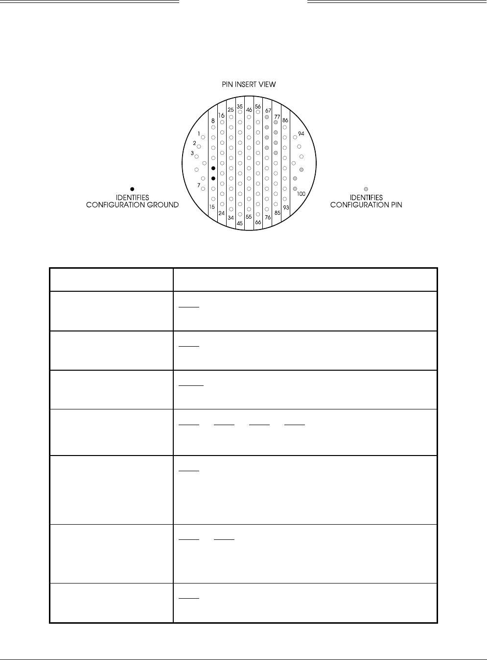
2.6.2 Configuration Jumpers
All installation dependent selections are defined via configuration jumpers. The configuration jumpers, as
detailed in table 2-3, are installed on the TRC mating connector (P1). Figure 2-4 shows the contact
arrangement for connector P1. Configuration ground is available at P1-12 and P1-13.
Figure 2-4. Connector P1 Contact Arrangement
Table 2-3. Configuration Jumpers
FUNCTION CONFIGURATION JUMPER
Airframe P1-98
Fixed Wing 1 (Open)
Rotor Craft 0 (Jumper to Configuration Ground)
Antenna P1-99
NY-164 1 (Open)
NY-156 0 (Jumper to Configuration Ground)
Antenna Position P1-100
Top 1 (Open)
Bottom* 0 (Jumper to Configuration Ground)
ARINC-429 Alternate Display P1-77 P1-78 P1-79 P1-80
None 1 1 1 1 (1 = Open)
ARINC 735 Type 1 Device** 1 1 1 0 (0 = Jumper to
Configuration Ground)
Heading Flag Sense P1-68
LOW 1 (1 = Open - If LOW level input on HDG_FLG+ (P1-53)
indicates valid heading or no valid heading input is
available or when ARINC 429 input is heading source.)
HIGH 0 (0 = Jumper to Configuration Ground - If HIGH level input on
HDG_FLG+ (P1-53) indicates valid heading.)
Heading Input Source P1-69 P1-70
None 1 1 (1 = Open)
Synchro 1 0 (0 = Jumper to Configuration Ground)
Stepper 0 1
ARINC 429 Bus 0 0
RS422 Interface P1-67
Data Recorder 1 (Open)
Alternate*** 0 (Jumper to Configuration Ground)
* See paragraph 2.3 Antenna Position
** ARINC-735 Type 1 device is a BFGAS designation that identifies the current display driver
*** Future Option

SKY497
Installation Manual
2-15
Rev. C
Heading flag logic, as detailed in table 2-4, is programmed with a jumper between P1-68 (Heading Flag
Sense) and configuration ground.
NOTE
If the heading system has a low level flag between 1.5 VDC and 2.7 VDC
(when valid), P1-68 (HEADING FLAG SENSE) should not be jumpered to
ground and P1-53 (HDG_FLG+) must remain unconnected.
Table 2-4. Heading Flag Action
Heading Flag Logic FLAG SENSE LOW
(P1-68 Open)
FLAG SENSE HIGH
(P1-68 Jumpered to ground.)
Heading Status VALID FLAGGED VALID FLAGGED
P1-53 Relative to P1-52
(HDG_FLG+ - HDG_FLG-) <1 V >5 V >5V <1V
2.6.3 Display Cable
The display cable connects the TRC to the WX-1000/SKY497 Display. If a WX-1000 Stormscope® Weather
Mapping System is installed, the same type cable is used to connect the TRC to a WX-1000 processor.
Refer to figure 2-2 (without WX-1000) or 2-3 (with WX-1000) for interconnect wiring information. Pinout
information relating to the WX-1000 processor and display is also provided in tables 2-5 and 2-6.
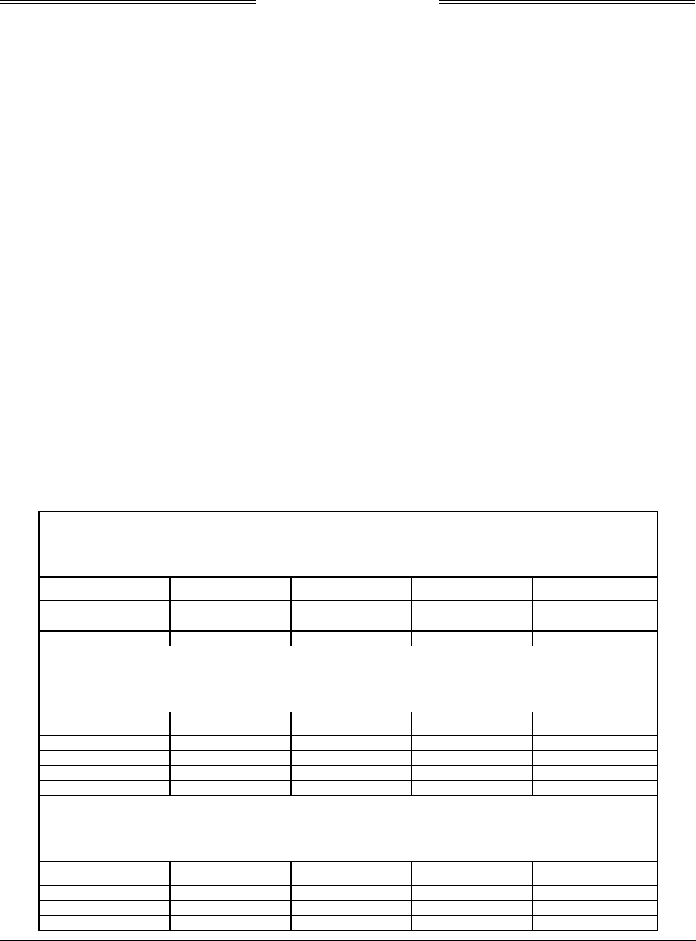
Table 2-5. WX-1000/SKY497 Display Connection
Display WIRE COLOR TRC
FUNCTION P101 SUB-CABLE WIRE P1
(Inner Jackets) 2
DPWR+15_OUT 19 WHITE WHITE P1-7
DPWR-15_OUT 14 WHITE ORANGE P1-6
DSPLY_GND 18 WHITE BLUE P1-14
HSYNC_OUT_HI 6 BLUE BLUE P1-49
HSYNC_OUT_LO 5 BLUE WHITE P1-48
VSYNC_OUT_HI 9 ORANGE WHITE P1-63
VSYNC_OUT_LO 10 ORANGE BLUE P1-62
VIDEO_OUT_HI 8 RED WHITE P1-38
VIDEOOUT_LO 7 RED BLUE P1-37
PWR_SW_HI 22 (SW2*) GREEN WHITE P1-11
PWR_SW-LO 23 (SW2*) GREEN BLUE P1-3
SFTKEY1_IN 13 BLACK WHITE P1-85
SFTKEY2_IN 12 BLACK BLUE P1-84
SFTKEY3_IN 25 YELLOW WHITE P1-83
SFTKEY4_IN 24 YELLOW BLUE P1-82
*SW2 required if WX-1000 Processor installed (see figure 2-2).

SKY497
Installation Manual
2-16
Rev. C
Table 2-6. WX -1000 Processor Connection
WIRE COLOR
FUNCTION WX-1000 Processor SUB-CABLE WIRE TRC497
SHIELD P301-5
PWRSWHI P301-21 GREEN WHITE SW2*
PWRSWLO P301-20 GREEN BLUE SW2*
+15 P301-3 WHITE WHITE P1-24
-15 P301-36 WHITE ORANGE P1-5
DSPGND P301-38 WHITE BLUE P1-15
HSYNCHI P301-6 WHITE BLUE P1-47
HSYNCLO P301-23 BLUE WHITE P1-46
VSYNCHI P301-40 ORANGE WHITE P1-61
VSYNCLO P301-7 ORANGE BLUE P1-60
VIDEOHI P301-22 RED BLUE P1-36
VIDEOLO P301-39 RED WHITE P1-35
SFTKEY1 P301-9 BLACK WHITE P1-76
SFTKEY2 P301-26 BLACK BLUE P1-75
SFTKEY3 P301-43 YELLOW WHITE P1-74
SFTKEY4 P301-44 YELLOW BLUE P1-73
*SW2 required if WX-1000 Processor installed (see figure 2-2).
Table 2-7 identifies U.S. vendors who sell approved display cables by the foot.
NOTE
Use of any cable not meeting BFG Avionics Systems specifications voids all
system warranties.
Table 2-7. Display Cable Vendors
U.S.
COMPANY
DISPLAY CABLE
P/N
WEIGHT
(LB PER 100 FT)
Dallas Avionics
1-800-527-2581
214-320-9776
FAX 214-320-1057
WX-3 10.5
Electronic Cable Specialists
414-421-5300
FAX 414-421-5301
3N6715 16
A.E. Petsche
817-461-9473
FAX 817 277 2887
TZDIS 13.1
PIC Wire and Cable
1-800-742-3191
414-246-0500
FAX 414-246-0450
WM25815 14.5
EDMO Distributors
1-800-235-3300
509-535-8280
FAX 1-800-828-0623
FAX 509-535-8266
WX-1000 Display ---
Required connectors and contact pins are supplied in the installation kit.
SKY497
Installation Manual
2-17
Rev. C
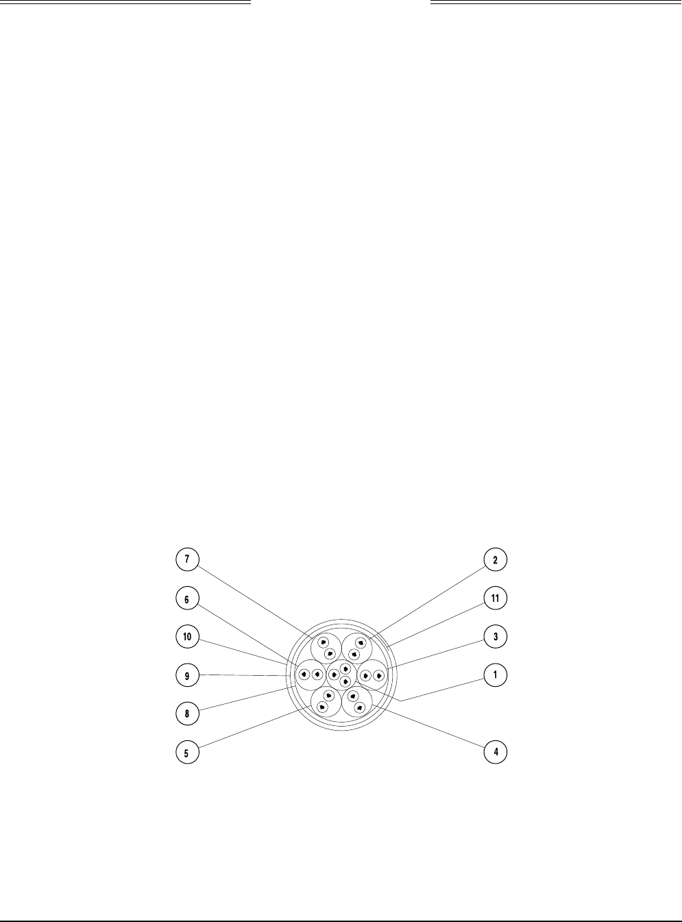
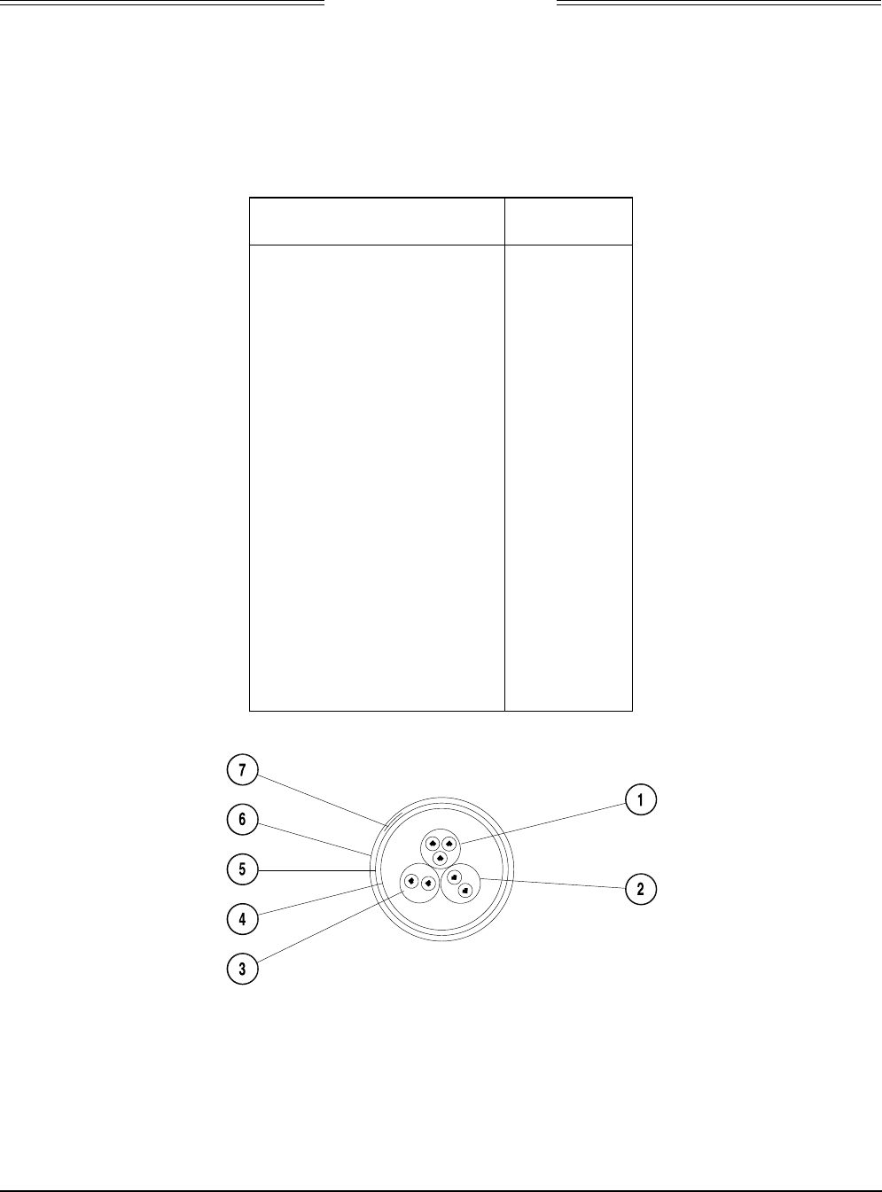
The display cable consists of the following (refer to figure 2-5).
1. Twisted, shielded, jacketed triad #22 AWG
Colors: White, Blue, Orange
Shield: Tin plated copper braid, 90% min.
Jacket: FEP .007 in. min., White jacket
2. Twisted, shielded, jacketed pair #24 AWG
Colors: White, Blue
Shield: Tin plated copper braid, 90% min.
Jacket: FEP .007 in. min., Blue jacket
3. Same as 2 except Orange jacket.
4. Same as 2 except Green jacket.
5. Same as 2 except Red jacket.
6. Same as 2 except Black jacket.
7. Same as 2 except Yellow jacket.
8. Aluminized Mylar® wrap.
9. #34 AWG braided shield.
10. FEP Teflon® jacket .013 in. - .023 in., Red tint.
11. Marker tape with Vendor P/N.
Figure 2-5. Display Cable
The sub-cable color-coded jackets and shields should be left on the sub-cables as close to the connectors as
practical to provide the required shielding and to identify the sub-cables.
SKY497
Installation Manual
2-18
Rev. C
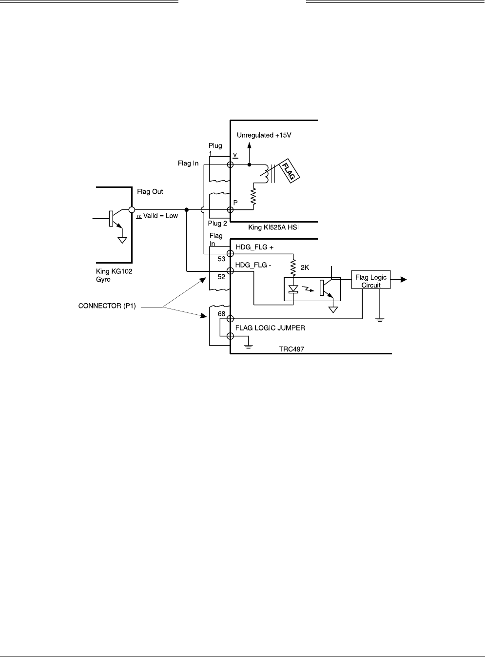
2.6.4 Heading Input Cable
The heading input cable connects the TRC497 to the aircraft heading system (refer to the Interconnect
Wiring Diagram, figure 2-2 or 2-3). This cable provides XYZ and HC aircraft heading information (or King
KCS55 stepper signals) to the TRC497. FLAG lines are also included in the heading input cable to provide
the TRC497 processor with flag status (or heading valid) information.
Figure 2-6 shows the TRC497 heading validation circuit of the King KCS55 that provides a heading valid
signal to the TRC497.
Figure 2-6. KCS55 Heading Flag Connection
If the heading source does not have a FLAG LO (-), the heading source FLAG HI(+) input is connected to
P1-53 (HDG_FLG+) and P1-52 (HDG_FLG-) is connected to ground.
If the heading system has a low level flag between 1.5 VDC and 2.7 VDC (when valid), P1-68 (HEADING
FLAG SENSE) should not be jumpered to ground and P1-53 (HDG_FLG+) must remain unconnected.
Table 2-8 lists some U.S. vendors who sell the required cable by the foot.
NOTE
Use of any cable not meeting BFG Avionics Systems specifications voids all system
warranties.
The synchro cable consists of the following (refer to figure 2-7):
1. Twisted, Shielded, Jacketed Triad #24 AWG
Colors: White, Blue, Orange
Shield: Tin Plated Copper Braid, 90% min.
Jacket: FEP .007 in. min., White
2. Twisted, Shielded, Jacketed Pair #24 AWG
Colors: White, Blue
Shield: Tin Plated Copper Braid, 90% min.
Jacket: FEP .007 in. min., Blue
3. Same as Item 2, except Orange jacket.
4. Aluminized Mylar® Wrap.
5. #34 AWG braided shield.
SKY497
Installation Manual
2-19
Rev. C
6. FEP Teflon® jacket .013 in. - .023 in., clear (translucent).
7. Marker tape with vendor P/N.
The sub-cable color-coded jackets and shields should be left on the sub-cables as close to the connector as
practical to provide the required shielding and to identify the sub-cables.
Table 2-8. Heading Input Cable Vendors
US
COMPANY
CABLE
P/N
Dallas Avionics
1-800-527-2581
214-320-9776
FAX 214-320-1057
Electronic Cable
Specialists
414-421-5300
FAX 414-521-5301
A.E. Petsche
817-461-9473
FAX 817-277-2887
EDMO Distributors
1-800-235-3300
805-295-6689
FAX 1-800-828-0623
FAX 805-295-6703
PIC Wire and Cable
1-800-742-3191
414-246-0500
FAX 414-246-0450
WX-5
(6.84 lb/
100 ft)
3N6607
(7.5 lb/
100 ft)
TZGYR
(6.84 lb/
100 ft)
WX-1000
SYNCHRO
WM25807
(7.2 lb/
100 ft)
Figure 2-7. Heading Input Cable

SKY497
Installation Manual
2-20
Rev. C
2.6.5 ARINC 429 Data Cables
ARINC 429 Data Input Cable. The two ARINC 429 receivers can be used to input data from other avionics
systems. The following labels are supported:
LABEL FUNCTION
164 Radio Altimeter (see note)
203 Barometric Altitude (Uncorrected)
320 Magnetic Heading
NOTE
The radio altimeter must provide full range output between 0 and 2500 feet. Not all
altimeters provide this full range output. The full range output can sometimes be
obtained as a mod to the radio altimeter. Check with the specific altimeter
manufacturer for compatibility and availability of modification, if necessary.
Data can be input at either low speed (12.5 kHz) or high speed (100 kHz). Both transmitters (data sources)
must be set to the same speed. The TRC will automatically adjust both receivers to the speed of the first
detected incoming data.
The TRC can only accept Radio Altimeter input from ARINC 429 source. The Barometric Altitude can be
ARINC 429 or Gilham Code. The Magnetic Heading can be ARINC 429, Synchro (XYZ) or Stepper
depending on the configuration pins and interconnect wiring. (See figure 2-2 or 2-3.)
NOTE
If 429 barometric altitude is used, it should be from the same source that is interfaced
with the transponder or it must be at least as accurate as that source, i.e., ± 125 ft.
Once the TRC detects valid ARINC 429 barometric altitude (Label 203) input, it will only use 429 data as a
source. ARINC 429 data cables are #22 AWG (minimum) twisted, shielded cables. Cable runs should be as
short as practicable.
Receiver “1” connection:
ARINC-429 RX 1A -to- P1-45
ARINC-429 RX 1B -to- P1-44
Receiver “2” connection:
ARINC-429 RX 2A -to- P1-43
ARINC-429 RX 2B -to- P1-42
Refer to figure 2-2 or 2-3 for detailed interconnect wiring information. Ground overall shields to the
airframe at the processor end only.
ARINC 429 Output Cable. The ARINC 429 transmitter can be used to output data to an external alternate
display (e.g., weather radar via BFGoodrich Avionics Systems RGC250). The output speed is 100 kHz.
ARINC 429 data cables are #22 AWG (minimum) twisted, shielded cables. Cable runs should be as short as
practicable.
Transmitter connection:
ARINC-429 TX 1A -to- P1-34
ARINC-429 TX 1B -to- P1-33
Refer to figure 2-2 for detailed interconnect wiring information.

SKY497
Installation Manual
2-21
Rev. C
2.6.6 Altimeter Input Cable
NOTE
Only one altimeter input source (Gray Code or ARINC 429, not both) should be
connected. The altimeter input should be from the same source that is interfaced with
the transponder or it must be at least as accurate as that source, i.e., ± 125 ft.
These signals are Gilham Code inputs coming from an airdata computer or altitude digitizer. These 10
lines may be connected in parallel with the aircraft transponder. If the aircraft is equipped with selectable
altitude encoders, connect the altitude inputs so that SKY497 is always connected to the selected encoder.
(Reference ARINC 572-1.)
Altitude encoder connection:
A1 -to- P1-40 B1 -to- P1-51 C1 -to- P1-58 D4 -to- P1-72
A2 -to- P1-41 B2 -to- P1-56 C2 -to- P1-59
A4 -to- P1-50 B4 -to- P1-57 C4 -to- P1-71
ALTITUDE COMMON - to P1-81
NOTE
If the aircraft has switched encoders that uses 28V RETURN or AIRCRAFT GROUND
as reference for encoder selection, then ALTITUDE COMMON should be left
unconnected.
For each connection use #22 AWG (minimum). Cable runs should be as short as practicable. Refer to figure
2-2 or 2-3 for detailed interconnect wiring information.
2.6.7 Audio Alert Output Cable
Audio output from the TRC is directly compatible with industry standard aircraft audio panels. There is no
internal audio adjustment. Audio levels are adjusted at the aircraft audio panel. This output is disabled
when a GPWS alarm is detected and remains disabled until the warning clears.
Use #22 AWG (minimum) twisted shielded pair cable for lengths up to 30 ft. . Cable runs should be as
short as practicable.
• Connect 600-ohm audio systems to P1-92 (AUDIO_H).
• Connect 150-ohm audio systems to P1-91 (AUIDO_L).
• Audio common is connected to P1-90 (AUDIO_C)
Refer to figure 2-2 or 2-3 for detailed interconnect wiring information.
2.6.8 Suppression Bus I/O
The TRC497 outputs (P1-89) a 100 µs (± 5 µs) suppression pulse on the aircraft suppression bus. In
addition, the TRC497 receives suppression signals from all other devices on the suppression bus (e.g.,
transponder, DME). (Reference ARINC 735-2 and DO-197.)
CAUTION
The aircraft transponder must have suppression circuitry to ensure that
SKYWATCH does not paint itself as a target (e.g., TA).
Any size low capacitance shielded cable may be used. Cable runs should be as short as practicable and the
shields should be grounded at both ends of the cable. Refer to figure 2-2 or 2-3 for detailed interconnect
wiring information.

SKY497
Installation Manual
2-22
Rev. C
2.6.9 Ground Proximity Warning System (GPWS) Input
This input senses a GPWS alarm and temporarily disables the audio alert output until the warning clears.
The input can be either a constant flag signal or an alternating flag output. The flag must be cleared for
five (5) seconds before the TRC accepts a “NO ALARM” condition and restores audible alerts.
NOTES
1. If the aircraft is equipped with GPWS, it must be connected to the TRC.
2. If the aircraft is not equipped with GPWS, leave this input unconnected..
For the GPWS input (P1-32) line, use #22 AWG (minimum) unshielded cable. Routing and length are not
critical to system operation.
2.6.10 SKYWATCH/
Stormscope
Mode Switch
The SKYWATCH/Stormscope mode switch (SW1) is required only if a WX-1000 Stormscope Weather
Mapping System is installed. This switch permits the flight crew to switch the display between the
SKY497 and WX-1000. If a TA (Traffic Advisory) is detected in the Stormscope mode, the display will
switch to the SKYWATCH mode. Refer to figure 2-3 for interconnect wiring information. Any general
purpose SPST toggle switch (3 Amp @ 28 VDC) may be used. Display mode switch cable routing and length
are not critical to system operation. Mount the switch at a location easily accessible to the pilot.
2.6.11 WX-1000 Maintenance Switch
ON/OFF control and display brightness is controlled through the OFF/BRT switch located on the WX-1000
display. An external NORMAL/OVERRIDE control over-ride switch (SW2) is required only if a WX-1000
Stormscope Weather Mapping System is installed. The override switch enables the SKYWATCH to be
powered-up if the WX-1000 processor has been removed for maintenance. During normal operation the
switch should remain in the NORMAL position and moved to OVERRIDE only if the WX-1000 processor
has been removed for service or if it is necessary to access the WX-1000 service menu. Refer to figure 2-3
for interconnect wiring information. Any general purpose DPDT toggle switch (3 Amp @ 28 VDC) may be
used. The maintenance switch cable routing and length are not critical to system operation. The switch can
be located in the avionics bay near the WX-1000 processor.
2.6.12 Squat Switch Input
This signal line is to be connected to the squat switch to sense when the aircraft is on the ground. If the
aircraft is not equipped with a squat switch, it is recommended that a squat switch be installed.
For the SQUAT input (P1-88) line, use #22 AWG (minimum) unshielded cable. Routing and length are not
critical to system operation.
If a squat switch is not available, this input could be tied to an airspeed switch inline with the pitot system
as an alternate input for the squat switch. In this configuration care should be taken to ensure the switch
is set to trigger at a speed consistent with take-off and landing.
On helicopter installations with skids, and a squat switch is not available, this input can be tied to the
collective switch. In this configuration care should be taken to ensure the switch is connected to provide a
ground when the aircraft is on the ground and open when the aircraft is airborne.
If it is not possible to install a squat switch, airspeed switch, or collective switch ground this input. With
this configuration the pilot must press soft-key (4), labeled →
→→
→OPR or →
→→
→STB, to toggle the system in and
out of standby. To display traffic, the pilot will have to switch out of standby by pressing the →
→→
→OPR
button.
With a squat switch installed, SKYWATCH will automatically switch out of standby (i.e, ABV/6nm) 8 to 10
seconds after takeoff and switch back to standby 24 seconds after landing. A squat switch would also
prevent the pilot from placing SKYWATCH in standby (i.e., pressing the →
→→
→STB button) while the aircraft
is in-flight.

SKY497
Installation Manual
2-23
Rev. C
2.6.13 Landing Gear Switch Input
This signal line is to be connected to the landing gear switch to sense the position of the landing gear.
For the GEAR input (P1-87) line, use #22 AWG (minimum) unshielded cable. Routing and length are not
critical to system operation.
If the aircraft does not have a landing gear switch input (e.g., fixed-gear aircraft), leave this input
unconnected. With this configuration, if no ARINC 429 compatible radio altimeter is installed, the system
will default to the highest TA sensitivity level (level B) and audio TA announcements (i.e., “traffic, traffic”)
will not be inhibited during takeoff and landing.
2.6.14 Power Cable
The power cable (not supplied) runs from the aircraft circuit breaker panel to the TRC. The power cable is
connected to the TRC using the MS3126F12-3S connector included in the TRC installation kit. For the
power cable, use #16 AWG (minimum) twisted shielded pair cable (Beldon 83322, Alpha 2826/2, or
equivalent).
NOTE
For 14 V aircraft systems a 7.5 A circuit breaker is required and for 28 V
systems a 5 A circuit breaker is required. The circuit breaker may be selected
to match components of the individual aircraft.
The positive wire (P8-A) connects to the circuit breaker. The negative wire (P8-B) connects to the aircraft
power return. Terminate the shield to airframe ground at the power source. Power cable routing and
length are not critical to system operation.
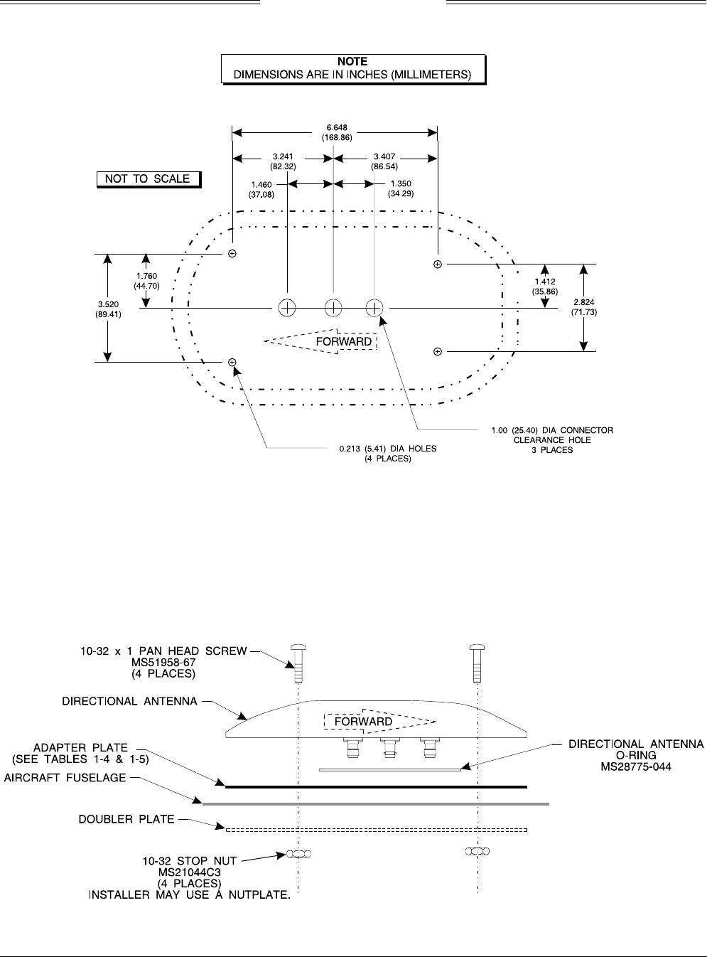
2.7 ANTENNA INSTALLATION
The following paragraphs provide installation details for directional antenna. The installer must ensure
the immediate antenna installation area is clean and prepared so that the antenna is electrically bonded
(metal-to-metal contact) to the aircraft. To provide optimum bonding through the mounting holes, prepare
the surfaces with Alodine No. 1001.
To facilitate mounting to the airframe, the dimensions shown in figure 2-8 can be used to locate and drill
mounting and connector access holes. Connection to the antenna should be made in accordance with the
system interconnect diagram (figure 2-2 or 2-3).
NOTE
A doubler plate (not supplied) is required to reinforce the aircraft skin.
1. Connect each of the three antenna cables. Check to ensure that each cable is connected to the correct
antenna connector. Each connector/cable has a matching color band (see note para 2.6.1).
2. Attach the antenna to the aircraft, with the special adapter plate and o-ring, using 10-32 hardware
provided. See figure 2-9.
NOTES
1. When mounting the antenna remove the O-ring from the bag and install it
in the O-ring groove on the bottom of the antenna.
2. The antenna must be sealed to the airframe. For pressurized aircraft, use
a sealant that meets the requirements of SAE AMS-S-8802 such as
Flamemaster® CS3204 class B. For non-pressurized aircraft, use a non-
corrosive sealant that meets the physical requirements of MIL-A-46146
such as General Electric RTV162.
SKY497
Installation Manual
2-24
Rev. C
Figure 2-8. Antenna Mounting Holes
Figure 2-9. Directional Antenna Installation
SKY497
Installation Manual
2-25
Rev. C
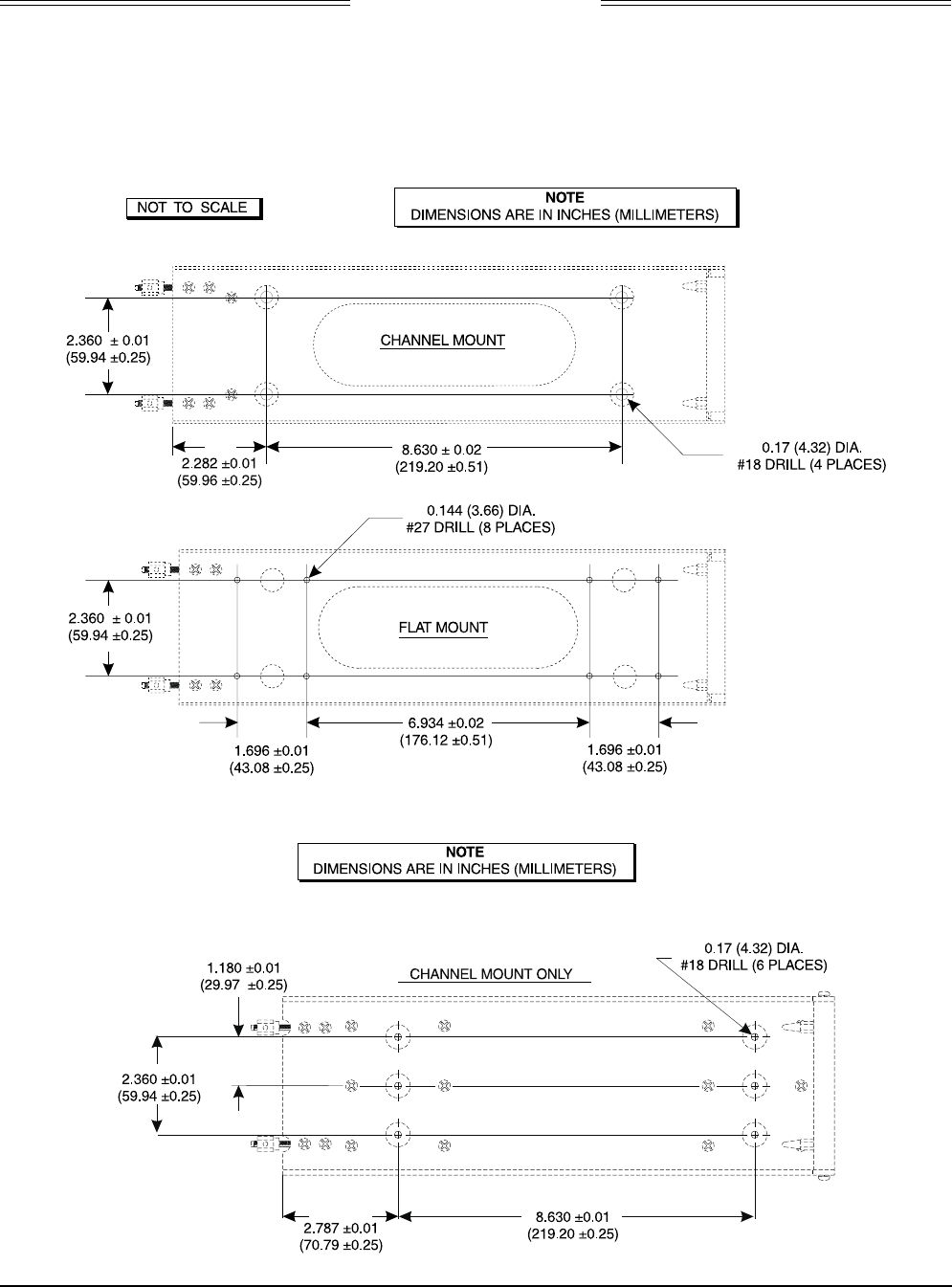
2.8 TRC MOUNTING TRAY INSTALLATION
To accommodate different space limitations, the standard TRC mounting tray (P/N 805-10870-001) can be
channel or flat mounted. To flat mount the tray, simply remove the eight 6-32 (Phillps) screws that secure
the channel to the tray. The ruggedized TRC mounting tray (P/N 805-10870-003), required for rotorcraft
installations, must be channel mounted.
Figure 2-10. Mounting Holes for Standard Mounting Tray, P/N 805-10870-001
Figure 2-11. Mounting Holes for Ruggedized Mounting Tray, P/N 805-10870-003

SKY497
Installation Manual
2-26
Rev. C
1. Position tray at the installation location.
2. Determine centers for mounting holes, and drill for required fasteners. See figure 2-10 (standard tray)
or 2-11 (ruggedized tray).
3. Secure tray in place using suitable 8-32 (channel mount) or 6-32 (flat mount) hardware.
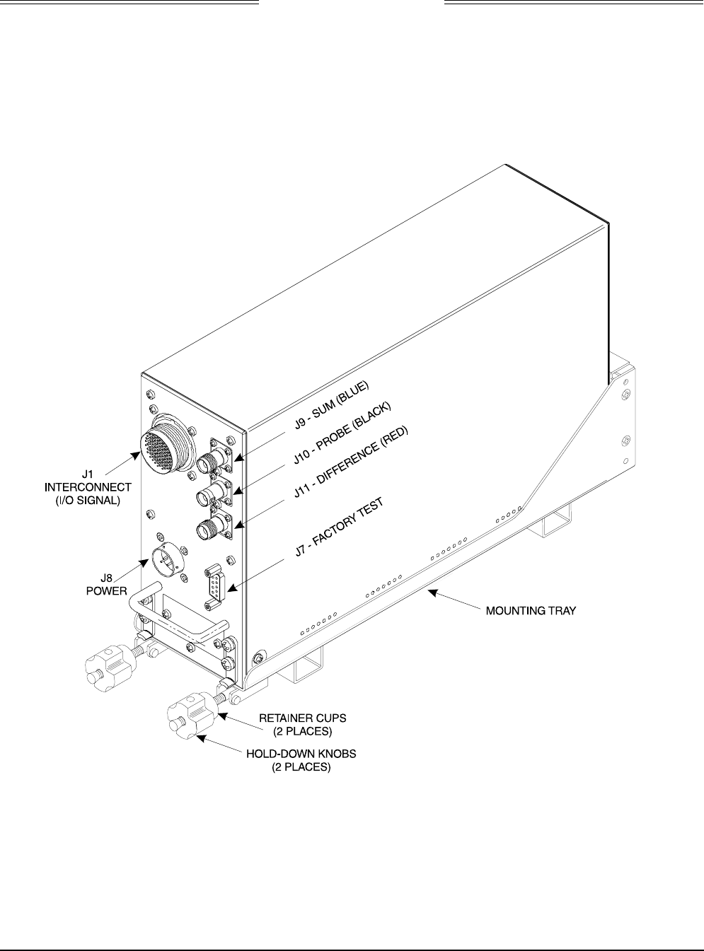
2.9 TRC INSTALLATION
CAUTION
Before placing the TRC into its mounting tray, de-energize or disconnect all
power and signal sources and loads used with the SKY497 system.
1. Slide the TRC into the mounting tray (see figure 2-12). Ensure that the rear hold-down pins on the
mounting tray are properly inserted into receptacles on the TRC.
2. Place the retainer cups over the TRC J-hooks. Secure the TRC to the mounting tray by tightening the
self-locking hold-down knobs.
3. Connect the three antenna inputs to the connectors on the front panel.
a. Connect the Sum port antenna connector (P9 - a TNC connector identified with a blue band) to
connector J9 (identified with blue marking).
b. Connect the Probe (Bit) port antenna connector (P10 - a BNC connector identified with a black
band) to connector J10.
c. Connect the Difference (Delta) port antenna connector (P11 - a TNC connector identified with a
red band) to connector J11 (identified with red marking).
4. Connect I/O Signal Cable (P1 - a 100-pin connector) to connector J1.
5. Connect the power cable (P8 - a three pin connector) to connector J8.
SKY497
Installation Manual
2-27
Rev. C
Figure 2-12. TRC497 Installation
SKY497
Installation Manual
2-28
Rev. C
2.10 MOUNTING THE WX-1000/SKY497 DISPLAY
The display mounts in a standard 3ATI panel cutout (figure 2-13). The unit may be mounted from the front
or rear. The following paragraphs describe the installation procedure.
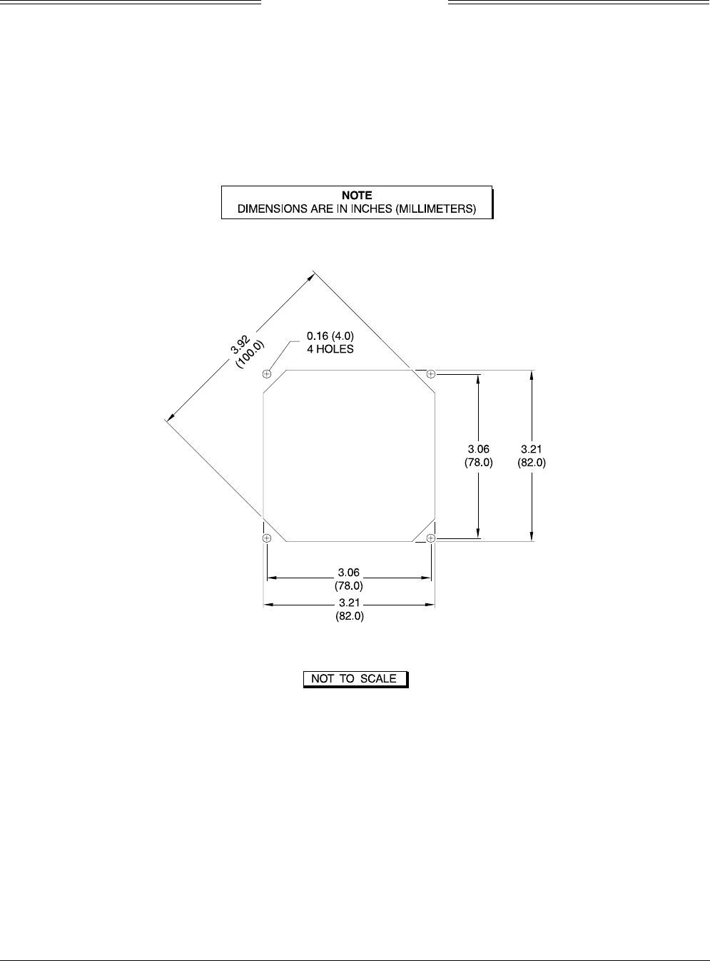
2.10.1 Panel Cutout.
Refer to figure 2-13 for the panel cutout and mounting hole dimensions. Drill and punch the required
holes. The instrument panel cutout is a standard 3ATI.
Figure 2-13. Instrument Panel Cutout and Mounting Holes
SKY497
Installation Manual
2-29
Rev. C
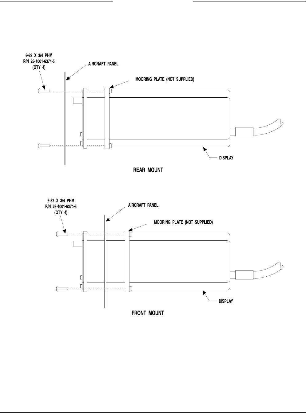
2.10.2 Display Installation
Figure 2-14 shows a typical display installation. The display can be mounted to the instrument panel from
the front or from the rear. An optional mooring clamp is available for increased stability in high-vibration
environments.
Figure 2-14. Display Installation
Use rivnuts® or a mooring clamp to secure the display to the instrument panel.
NOTE
1. The mooring clamp is not furnished with the display.
2. A mooring clamp (P/N 78-8060-5856-2) can be ordered when the order for the
display is placed.
3. A 3ATI mooring clamp is also available from:
MSP, Incorporated
R.R. 4, Box 383A
Nashville, Indiana 47448
Tel. (812) 988-6623 or FAX (812) 988-6181

SKY497
Installation Manual
2-30
Rev. C
This page intentionally left blank.
SKY497
Installation Manual
3-1
Rev. C
CHAPTER 3
INSTALLATION CHECKOUT
3.1 INTRODUCTION
This section contains instructions for using the BFGoodrich Avionics Systems TT391 Flightline Tester to
do post-installation checkout of the BFG Avionics Systems SKY497. Detailed setup, operation and
maintenance information for the TT391 Flightline Tester is provided in the TT391 Instruction Manual.
NOTES
1. This procedure assumes familiarity with the set up and operation of the TT391
Flightline Tester.
2. All test equipment used in completing these tests shall be calibrated in
accordance with the manufacturer's recommendations.
3. This section provides checkout information for the BFGoodrich Avionics
Systems SKY497 using the WX-1000 Display. If using an alternate display use
Appendix E for installation checkout.
4. Checkout of the WX-1000 processor should be done in accordance with the
procedures detailed in the WX-1000 Installation Manual.
This procedure will validate the installation and return to service of the BFGoodrich Avionics Systems
SKY497.
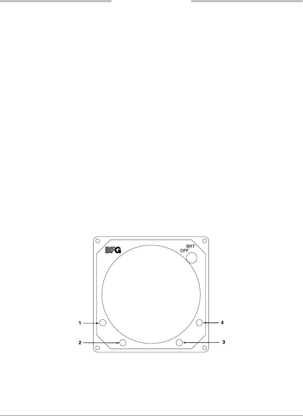
3.2 CONTROLS
All operating controls are located on the front of the indictor. Figure 3-1 shows the locations of the controls.
Complete operating instructions for the SKY497 are provided in the SKY497 Pilot's Guide supplied with
each system.
Figure 3-1. Controls
OFF/BRT
Switch
Power is applied by rotating the knob clockwise past the detent. Continued
clockwise rotation increases display brightness.
1, 2, 3, & 4
Pushbuttons
Also referred to as soft-keys (1), (2), (3), and (4). In every operating mode a label
identifying the button function will be displayed next to the button.
SKY497
Installation Manual
3-2
Rev. C
3.3. CHECKOUT PROCEDURE
The TT391 Flightline Tester simulates both a ground based secondary surveillance radar (SSR) and an
airborne transponder. With the SKY497 set to GROUND TEST (i.e., the barometric altimeter is simulated
to 50,000 ft, heading simulated to 0 degrees, and the radar altimeter simulated to 2,500 ft) the TT391 will
simulate two targets; a Traffic Advisory (i.e., a solid circle) at ¼ nm and Other Traffic (i.e., open diamond)
at 4.5 nm. Both targets will be displayed in level flight at own aircraft altitude (i.e., "00" displayed above
the traffic symbol).
If the indications given in the following procedure, except for the Flightline Tester, are not obtained, refer
to the troubleshooting procedures in Chapter 4. If indications given for the Flightline Tester are not
obtained, refer to the maintenance section of the TT391 Instruction Manual.
1. Make sure the aircraft's transponder is in the STBY mode and the DME is turned OFF. At the
aircraft's instruments, verify all compass/HSI flags are valid.
NOTE
After power up, it may take a couple of minutes for the altitude encoder to
return a valid altitude to the transponder and SKY497.
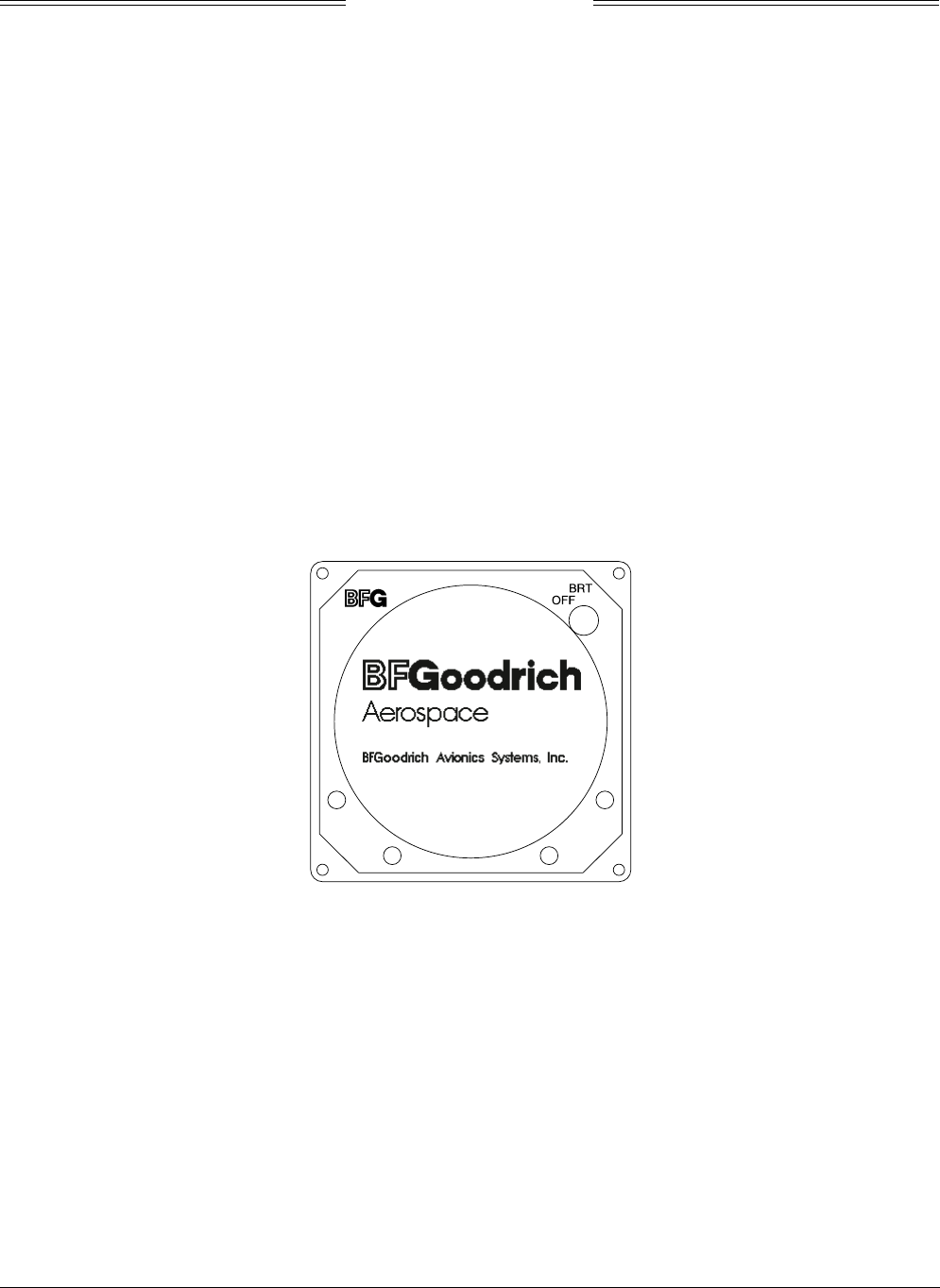
2. Turn SKY497 ON. The display will show a start-up screen similar to one shown in figure 3-2. After
start-up screen appears, rotate the OFF/BRT switch. Verify that clockwise rotation increases display
brightness.
Figure 3-2. Start-up Screen
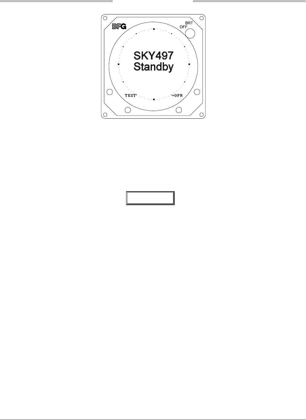
After approximately thirty seconds the display will show the STANDBY screen (see figure 3-3).
NOTE
If the TRC has not been calibrated to the directional antenna (see step 3)
the display may show a “SKY497 FAILED” message.
SKY497
Installation Manual
3-3
Rev. C
Figure 3-3. Standby Screen
3. Turn SKY497 OFF and then enter the Service Menu (see paragraph 4.4) by holding the left two
buttons (soft-keys 1 and 2) depressed as the system is turned ON.
4. From the Service Menu, calibrate the TRC to the directional antenna (see paragraph 4.4.1).
5. Return to the Service Menu and select System Data (see paragraph 4.4.3).
a. Verify status and save the configuration jumpers (see paragraph 4.4.3.2, Configuration).
WARNING
Verify displayed antenna position matches antenna location on the aircraft
(top or bottom). Failure to do so could give incorrect traffic bearing.
b. Verify that the system has recognized and is responding to installed sensors (see paragraph
4.4.3.3, Data Monitor).
1) Sequence through each Data Monitor display page.
2) Verify that the sensor information displayed is correct.
3) If the information is not correct, the sensor has failed to communicate with the TRC.
Check operation of the sensor and cables between the TRC and sensor.
4) Change the status of the landing gear, squat switch, altitude, and heading sensors. Verify
that the display shows the correct input (i.e., sensing of these signals).
6. Exit the service menu and do the SKYWATCH self-test (see para 3.4).
7. Turn SKY497 OFF, return to the Service Menu and select Ground Test (see paragraph 4.4.4).
8. Verify operation of range function. Soft-key (3) is labeled to indicate the current range. Press soft-key
(3) to toggle the display range between 2 and 6 nm.
9. Select the 6 nautical mile range.
10. Verify that the system toggles through the altitude display modes. Soft-key (2) is labeled to indicate
the current mode. Press Soft-key (2) to select normal (NRM), below (BLW), and above (ABV).
11. Select the NRM (normal) mode.

SKY497
Installation Manual
3-4
Rev. C
12. Position the aircraft with the nose aligned on any 90 degree heading. Avoid areas within 250 ft of
obstructions (e.g., hangers, large aircraft, control towers, etc.) where there is a potential for multipath
problems. Locate and mark test points at 30 degree intervals (i.e., 000, 030, 060, 090, 120, 150, 180,
210, 240, 270, 300, and 330 degrees) with respect to the directional antenna. Mark these points at the
same distance, between 100 and 150 ft, from the aircraft.
13. Position the TT391 Flightline Tester on one of the test points identified in previous step.
CAUTION
The Flightline Tester is not weatherproof when the lid is open. Do not setup
or operate the Flightline Tester in conditions of rain, sleet, etc.
14. Setup and verify operation of the TT391 Flightline Tester:
a. Open the chassis lid and remove the lid from the chassis by sliding the lid off of the hinge pins
(sliding it to the right). The lid "stay" must be removed from the lid before mounting. The stay
will pop off of the lid. (The stay is the hinged part that props the lid open on the chassis).
NOTE
The Patch Antenna may be used without a tripod. The Patch Antenna can be
held, or secured, and pointed towards the SKYWATCH aircraft under test
WITH THE MOUNTING STUD POINT TOWARD THE GROUND. This orientation is
critical.
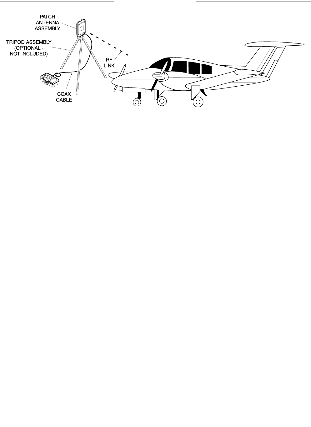
b. Mount the chassis lid, with the Patch Antenna facing the aircraft, onto a tripod (not included).
The tripod must be capable of holding the antenna (approximately 2.5 lb) and must provide a
standard base mounting stud threaded 1/4"-20. A typical tripod mount is shown in figure 3-4.
c. If the internal batteries are being utilized, proceed to sub-step f. If the Flightline Tester AC
Converter Power Supply is to be utilized, proceed to sub-step d.
d. Connect the AC Converter Power Supply cable connector to the chassis external connector.
e. Connect the AC Converter Power Supply input power cable connector to one of the following AC
sources:.
•115 Vac, 60 Hz
•115 Vac, 400 Hz
f. Set the Flightline Tester POWER switches to the ON position.
g. Verify that the LOW indicator is not steady on (it may flash). If the LOW indicator remains on
(i.e., lit), perform one of the following three options.
•Use the AC Converter Power Supply to power the unit.
•Recharge the internal batteries.
•Replace the internal batteries.
h. Set the SELF-TEST switch to the 1030 position and verify that the 1030 indicator blinks on for
1/2 second every 5 seconds.
i. Set the SELF-TEST switch to the 1090 position and verify that the 1090 indicator blinks on for
1/2 second every 5 seconds.
j. Set SELF-TEST switch to center position (off). Set the POWER switch to the OFF position.
NOTE
Care should be taken to ensure that the Patch Antenna is connected to TT391
connector J1 and NOT J2. IF THE PATCH ANTENNA IS CONNECTED TO
J2 THE TT391 WILL NOT FUNCTION CORRECTLY.
k. Connect the Flightline Tester coax cable to J3 on the Patch Antenna and to connector J1 in the
chassis. (J2 should remain capped by the dust cover).
SKY497
Installation Manual
3-5
Rev. C
Figure 3-4. Typical Patch Antenna Tripod Mount
15. From each test point (see step 12):
a. Position the TT391 Patch Antenna facing the SKYWATCH aircraft under test.
b. Set the TT391 POWER switch to the ON position.
c. Verify that the display shows, in the direction (± 30 degrees) of the TT391, two targets; a Traffic
Advisory (i.e., a solid circle) at ¼ nm and Other Traffic (i.e., open diamond) at 4.5 nm. Both
targets will be displayed in level flight at own aircraft altitude (i.e., "00" displayed above the
traffic symbol).
NOTES
1. If the display reflects a gross error in target bearing, check the directional
antenna cables at TRC connectors J9 (sum port) and J11 (difference port).
They may be reversed. A further indication of this condition would be a
target that moved in a counter-clockwise direction when the TT391 is
moved in a clockwise direction.
2. Multiple targets or a faulty bearing may result from multipath distortion
(see step 1).
3. During these tests, the SKY497 may detect and display other active
targets.
4. To obtain a better line of sight, it may be necessary to elevate the patch
antenna.
d. Set the TT391 POWER switch to the OFF. Repeat procedure from each test point. Step 15 can
be done from the last test point.
NOTE
To prevent SKYWATCH from tracking the movement of the test-set, it is
necessary to set the TT391 POWER switch to OFF after completing each
bearing measurement.
16. Return the TT391 assemblies to their position in the aluminum carrying case.
17. Restart SKYWATCH by cycling power OFF and then ON.
18. Connect an oscilloscope to the suppression bus and verify that the SKY497 suppression pulse (100 µs
±5 µs) exceeds +15 V dc. If less than +15 V dc the suppression bus is overloaded. Check all equipment
connected to the bus. Repair/replace the offending device.
19. This completes the post installation checkout procedure.
SKY497
Installation Manual
3-6
Rev. C
3.4 SELF TEST
1. Turn SKYWATCH OFF and then:
a. Make sure the aircraft's transponder is in the STANDBY, ON, or ALT mode.
NOTE
After power up, it may take a couple of minutes for the altitude encoder to
return a valid altitude to the transponder and SKY497.
b. If installed, power up the radio altimeter.
c. Make sure all compass/HSI flags are cleared from the aircraft's instruments.
2. Turn SKYWATCH ON. The display should show a start-up screen similar to one shown in figure 3-2.
3. After approximately thirty seconds, observe the STANDBY screen and then press the TEST button
(soft-key (1)).
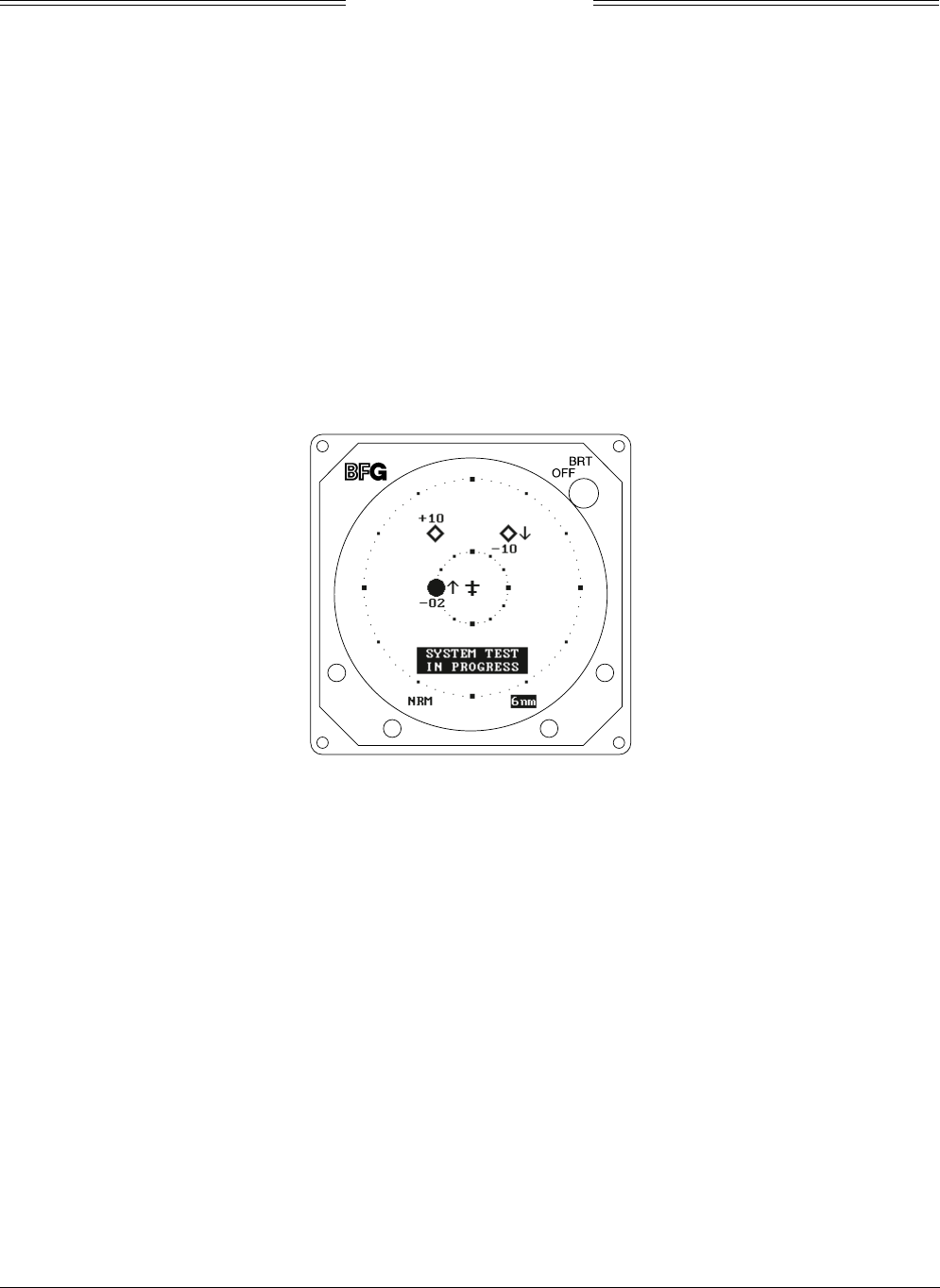
4. The display should present a screen similar to that shown in figure 3-5.
Figure 3-5. Self Test Screen
5. If SKYWATCH passes the self-test, the system will return to the STANDBY screen (see figure 3-3)
and the voice message, "TRAFFIC ADVISORY SYSTEM TEST PASSED," will be enunciated over the
cockpit audio system.
6. If you do not hear the voice message or if the voice message is of insufficient volume:
a. Check headphones/speaker and aircraft audio panel switch settings.
NOTE
Audio levels are adjusted at the aircraft audio panel. There is no internal
audio adjustment.
SKY497
Installation Manual
3-7
Rev. C
b. Check audio connection to the TRC:
1) 600-ohm audio systems should be connected to P1-92 (AUDIO_H).
2) 150-ohm audio systems should be connected to P1-91 (AUDIO_L).
3) Audio common is connected to P1-90 (AUDIO_C).
NOTE
Audio output from the TRC is transformer isolated.
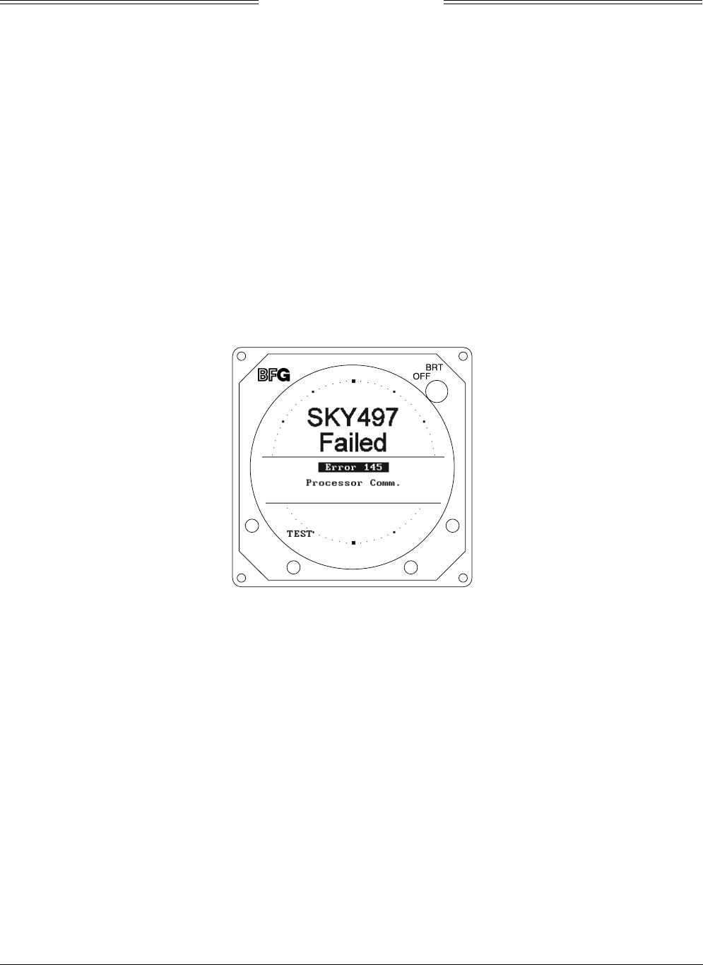
7. If SKYWATCH fails the self-test:
a. The "SKY497 Failed" screen (see figure 3-6) with an error message indicating the type of failure
will be displayed.
b. The voice message, "TRAFFIC ADVISORY SYSTEM TEST FAILED", will be enunciated over the
cockpit audio system.
c. Soft-key (1) will be labeled TEST. To re-test, press soft-key (1).
d. Soft-keys (2), (3), and (4) are not used.
Figure 3-6. Self Test Failed Screen
e. Refer to the fault isolation procedures in Chapter 4.

SKY497
Installation Manual
3-8
Rev. C
This page intentionally left blank.