LG Electronics USA 55LV555HUA LCD TV/Monitor User Manual SAC34134301 Edit1
LG Electronics USA LCD TV/Monitor SAC34134301 Edit1
Contents
- 1. User manual 1 of 5
- 2. User manual 2 of 5
- 3. User manual 3 of 5
- 4. User manual 4 of 5
- 5. User manual 5 of 5
User manual 2 of 5
PREPARATION
32
ANTENNA IN
PREPARATION
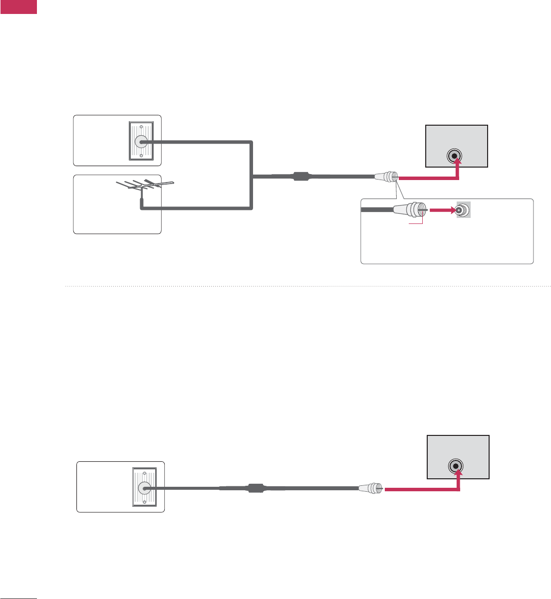
ANTENNA OR CABLE CONNECTION
1. Antenna (Analog or Digital)
This image refers to using a Wall Antenna Socket or Outdoor
Antenna without a Cable Box Connection.
2. Cable
Wall
Antenna
Socket
Outdoor
Antenna
(VHF, UHF)
Cable TV
Wall Jack
Multi-family Dwellings/Apartments
(Connect to wall antenna socket)
RF Coaxial Wire (75 Ω)
RF Coaxial Wire (75 Ω)
Single-family Dwellings /Houses
(Connect to wall jack for outdoor antenna)
Be careful not to bend the copper wire
when connecting the antenna.
Copper Wire
- For optimum picture quality, adjust the antenna direction if needed.
■To improve the picture quality in a poor signal area, please purchase a signal amplifier and install properly.
■If the antenna needs to be split for two TV’s, install a 2-Way Signal Splitter.
■If the antenna is not installed properly, contact your dealer for assistance.
■To prevent damage, do not connect to the power outlet until all connections are made between the devices.
ANTENNA IN
This image refers to using a cable connection without a cable box.
- If you experience a poor signal when using cable, make sure the RF cable is screwed in completely.
Contact your cable company is a poor signal persists.
PREPARATION
33
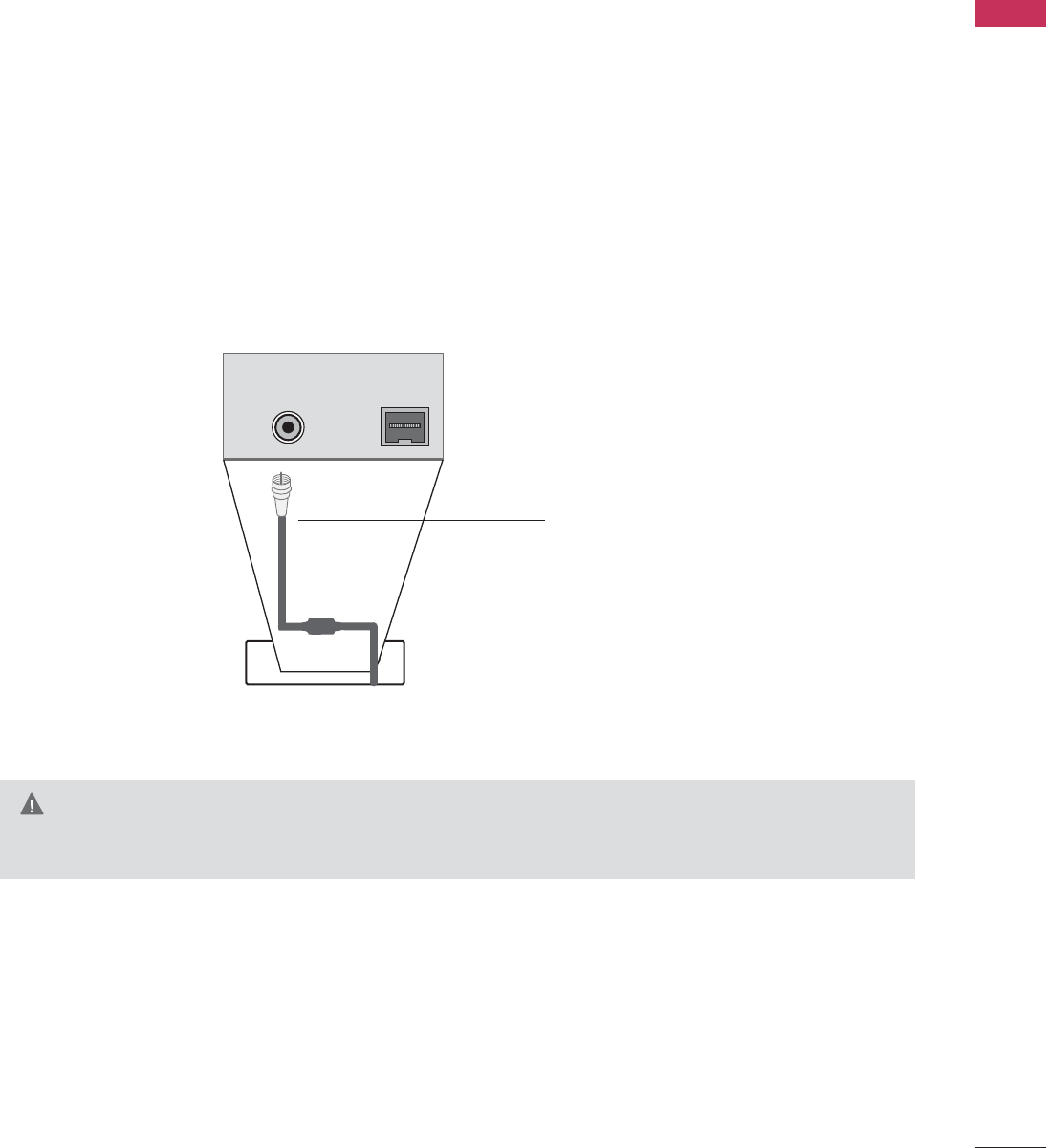
MPI CARD SLOT / PPV CARD INSTALLATION
(Except 47/55LD650H, 32/37/42/47/55LV555H)
1. Remove the two MPI card retainer screws.
2. Pull out current MPI card far enough so that the RF cable can be detached from the old card.
3. Detach RF cable.
4. Place new PPV card into slot and slide it in far enough to reconnect RF cable.
5. Insert card all the way into the slot making sure it is fully seated into back plane connector.
6. Replace the two card retainer screws.
The MPI card is equipped with an RF jack for antenna/cable signal source connection.
This card can be removed and replaced with a third-party PPV (Pay-Per-View) card.
MPI Card Removal / PPV Card Installation
RF CABLE
ANTENNA IN M.P.I.
M.P. I.
Card Slot
G
There is an RF cable connected to the back of the card. Remove the card slowly.
WARNING
EXTERNAL EQUIPMENT SETUP
34
HD RECEIVER SETUP
EXTERNAL EQUIPMENT SETUP
This TV can receive Digital Over-the-air or Digital Cable signals without an external digital set-top box. However,
if you do receive digital signals from a digital set-top box or other digital external device, refer to the figure as
shown below.
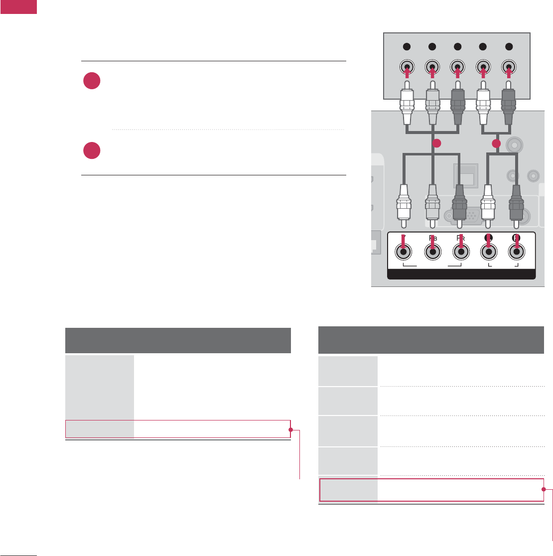
Component Connection
1. How to connect
Connect the video outputs (Y, PB, PR)of the digital set-
top box to the
COMPONENT IN VIDEO
jacks on
the TV. Match the jack colors (Y = green, PB= blue, and
PR= red).
Connect the audio output of the digital set-top box to
the
COMPONENT IN AUDIO
jacks on the TV.
2
1
2. How to use
■Turn on the digital set-top box.
(Refer to the owner’s manual for the digital set-top box.)
■Select
Component
input source using the
INPUT
button
on the remote control.
■To prevent the equipment damage, never plug in any power cords until you have finished connecting all equipment.
■Image shown may differ from your TV.
U
RESET
LAN
(SERVICE ONLY)
COMPONENT IN
VIDEO
AUDIO
R
(
S
VIDEO
AUDIO
COMPONENT IN
RGB(PC) AUDIO
(RGB/DVI)
RGB IN
TV-LINK
CFG
Y L RP
B
P
R
12
Y, CB/PB, CR/PR
Supported Resolutions
Horizontal Vertical
Frequency(kHz)Frequency(Hz)
15.73 59.94
15.73 60.00
31.47 59.94
31.47 60.00
44.96 59.94
45.00 60.00
33.72 59.94
33.75 60.00
67.50 60.00
Resolution
720x480i
720x480p
1280x720p
1920x1080i
Signal
480i
480p
720p
108 0 i
108 0 p
Component
Yes
Yes
Yes
Yes
Yes
HDMI
No
Yes
Yes
Yes
Yes
1920x1080p
For 37/42/47/55LD650H, 37/42LD655H,
37/42LD660H, 37/42LD665H,
37/42/47/55LV555H
For 37/42/47/55LD650H, 37/42LD655H,
37/42LD660H, 37/42LD665H,
37/42/47/55LV555H
EXTERNAL EQUIPMENT SETUP
35
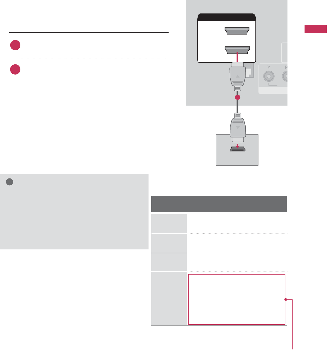
HDMI Connection
Connect the digital set-top box to
HDMI/DVI IN 1
(DVI)
or
2*
jack on the TV.
No separate audio connection is necessary.
HDMI supports both audio and video.
1. How to connect
2. How to use
■Turn on the digital set-top box.
(Refer to the owner’s manual for the digital set-top box.)
■Select
HDMI1
or
HDMI2
input source with using the
INPUT
button on the remote control.
2
1
HDMI-DTV
HDMI/DVI IN
2
1(DVI)
RJP
INTERFACE
VI
D
RGB
HDMI/DVI IN
2
1(DVI)
HDMI-DTV OUTPUT
1
Horizontal Vertical
Frequency(kHz)Frequency(Hz)
31.47 59.94
31.47 60.00
44.96 59.94
45.00 60.00
33.72 59.94
33.75 60.00
26.97 23.94
27.00 24.00
33.71 29.97
33.75 30.00
67.432 59.939
67.50 60.00
Resolution
720x480p
1280x720p
1920x1080i
G
If the HDMI cables don’t support High Speed
HDMI, it can cause flickers or no screen display. In
this case use the latest cables that support High
Speed HDMI.
G
HDMI mode supports PCM, Dolby Digital audio
format.
NOTE
!
1920x1080p
For 37/42/47/55LD650H, 37/42LD655H,
37/42LD660H, 37/42LD665H,
37/42/47/55LV555H
*HDMI2: Except 32/37/42/47/55LV555H
EXTERNAL EQUIPMENT SETUP
36
EXTERNAL EQUIPMENT SETUP
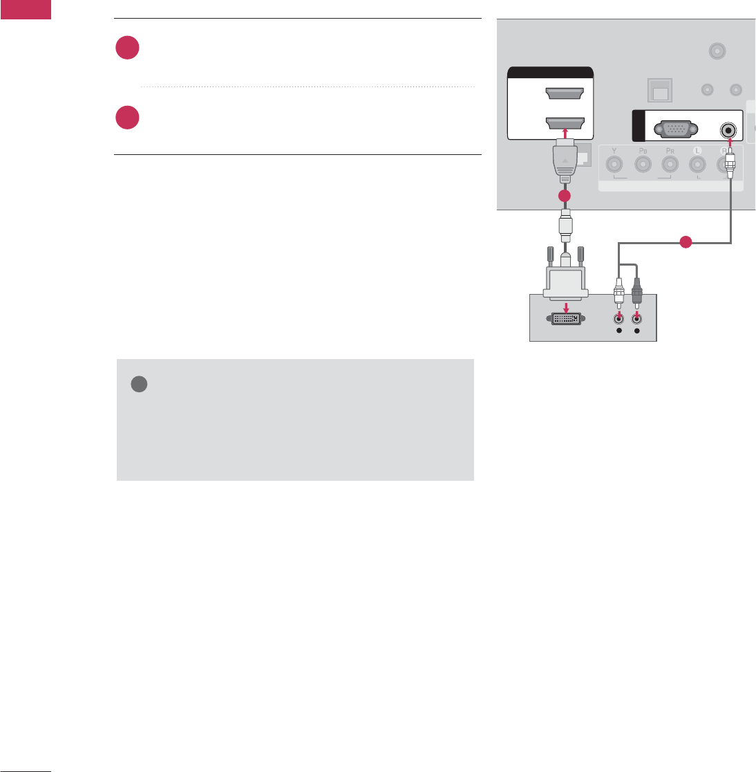
DVI to HDMI Connection
RGB(PC)
AUDIO
(RGB/DVI)
RGB IN
UPD
A
RESET
LAN
(SERVICE ONLY)
RJP
INTERFACE
COMPONENT IN
VIDEO
AUDIO
R
(
S
HDMI/DVI IN
2
1(DVI)
LR
DVI-DTV OUTPUT
LR
TV-LINK
CFG
C
O
1
2
G
G
A DVI to HDMI cable or adapter is required for this
connection. DVI doesn't support audio, so a separate
audio connection is necessary.
NOTE
!
Connect the DVI output of the digital set-top box to
the
HDMI/DVI IN 1 (DVI)
jack on the TV.
Connect the audio output of the digital set-top box to
the
AUDIO (RGB/DVI)
jack on the TV.
1. How to connect
2. How to use
■Turn on the digital set-top box. (Refer to the owner’s man-
ual for the digital set-top box.)
■Select the
HDMI1
input source on the TV using the
INPUT
button on the remote control.
2
1
EXTERNAL EQUIPMENT SETUP
37
DVD SETUP
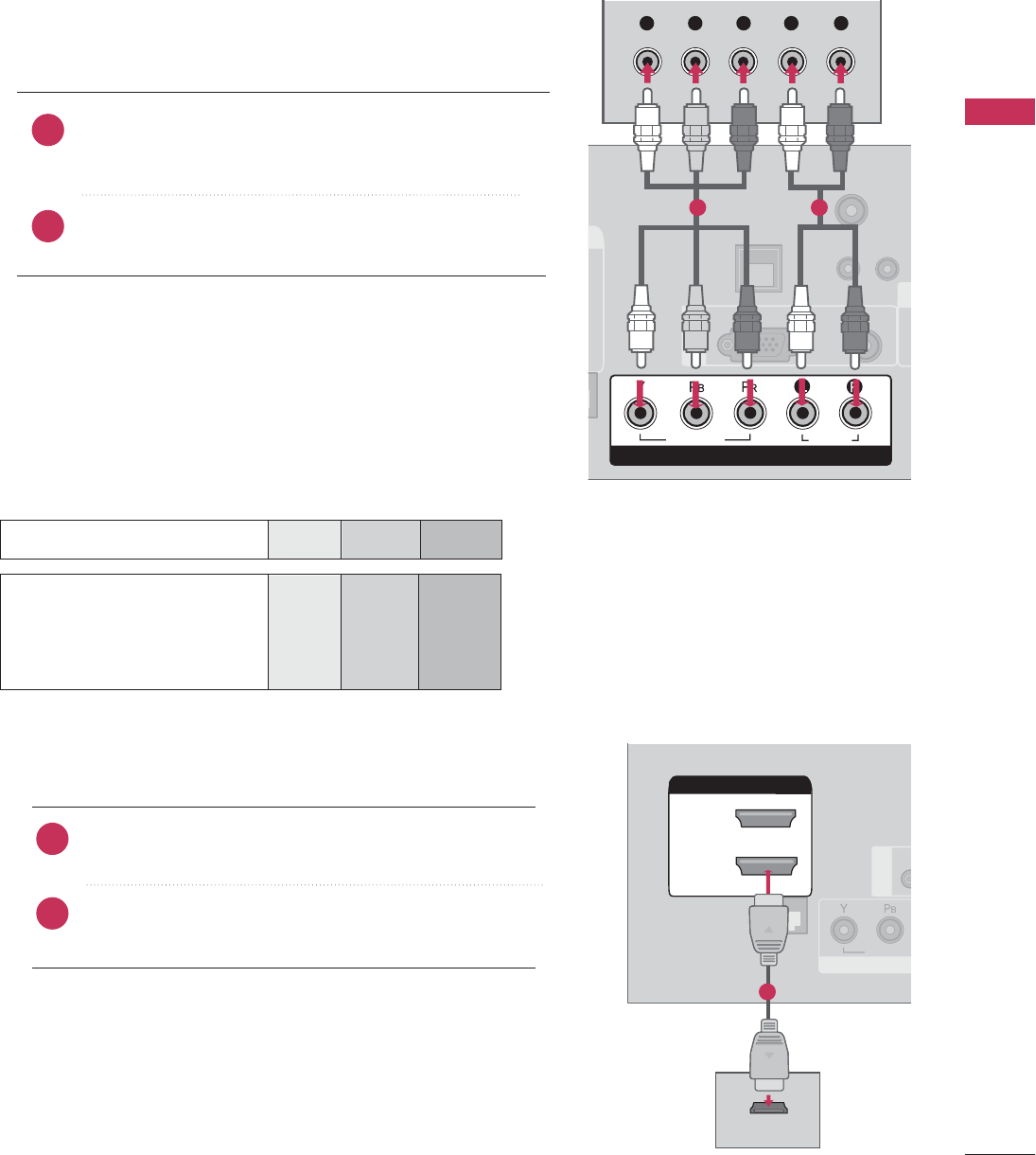
Component Connection
Component Input ports
To get better picture quality, connect a DVD player to the component input ports as shown below.
Component ports on the TV
YPBPR
Video output ports
on DVD player
Y
Y
Y
Y
PB
B-Y
Cb
Pb
PR
R-Y
Cr
Pr
Connect the video outputs (Y, PB, PR)of the DVD to the
COMPONENT IN VIDEO
jacks on the TV.
Match the jack colors (Y = green, PB = blue, and PR = red).
Connect the audio outputs of the DVD to the
COMPONENT IN AUDIO
jacks on the TV.
1. How to connect
2. How to use
■Turn on the DVD player, insert a DVD.
■Select the
Component
input source on the TV using the
INPUT
button on the remote control.
■Refer to the DVD player's manual for operating instructions.
2
1
U
RESET
LAN
(SERVICE ONLY)
COMPONENT IN
VIDEO
AUDIO
R
(S
VIDEO
AUDIO
COMPONENT IN
RGB(PC) AUDIO
(RGB/DVI)
RGB IN
TV-LINK
CFG
Y L RP
B
P
R
1 2
HDMI Connection
Connect the HDMI output of the DVD to the
H
HDMI/DVI IN 1 (DVI)
or
2 *
jack on the TV.
No separate audio connection is necessary.
HDMI supports both audio and video.
1. How to connect
2. How to use
■Select the
HDMI1
or
HDMI2
input source on the TV
using the
INPUT
button on the remote control.
■Refer to the DVD player's manual for operating instructions.
2
1
(
S
HDMI/DVI IN
2
1(DVI)
RJP
INTERFACE
CO
M
VIDEO
HDMI/DVI IN
2
1(DVI)
HDMI OUTPUT
RGB IN
1
EXTERNAL EQUIPMENT SETUP
38
EXTERNAL EQUIPMENT SETUP
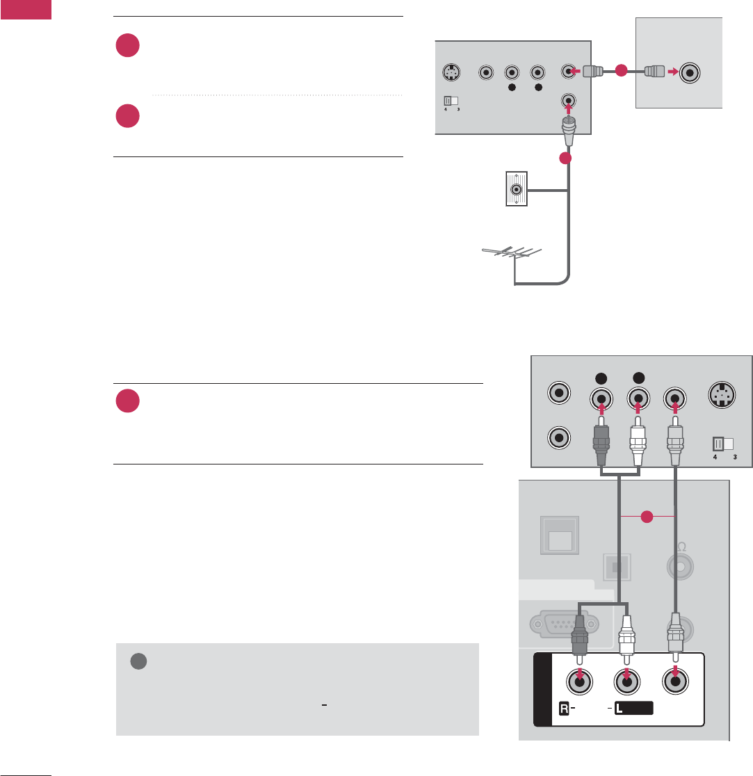
VCR SETUP
Antenna Connection
■To avoid picture noise (interference), leave an adequate distance between the VCR and TV.
L R
S-VIDEO VIDEO
OUTPUT
SWITCH
ANT IN
ANT OUT
ANTENNA IN
Wall Jack
Antenna
1
2
Connect the RF antenna out socket of the
VCR to the A
ANTENNA IN
socket on the
TV.
Connect the antenna cable to the RF
antenna in socket of the VCR.
1. How to connect
2. How to use
■Set VCR output switch to 3 or 4 and then
tune TV to the same channel number.
■Insert a video tape into the VCR and press
PLAY on the VCR. (Refer to the VCR owner’s
manual.)
2
1
Composite (RCA) Connection
Connect the
AUDIO
/
VIDEO
jacks between TV and
VCR. Match the jack colors (Video = yellow, Audio Left
= white, and Audio Right = red)
1. How to connect
2. How to use
■Insert a video tape into the VCR and press PLAY on the
VCR. (Refer to the VCR owner’s manual.)
■Select the
AV1
input source on the TV using the
INPUT
button on the remote control.
■If connected to
AV IN 2
, select
AV2
input source on the TV.
1
G
If you have a mono VCR, connect the audio cable
from the VCR to the
AUDIO L/MONO
jack of the
TV.
NOTE
!
L
R
S-VIDEO
VIDEO
OUTPUT
SWITCH
ANT IN
ANT OUT
OPTICAL
DIGITAL
AUDIO OUT
UPDATE
AV IN 1
AUDIO
VIDEO
/
REMOTE
CONTROL
OUT
SPEAKER
OUT
8
RS-232C IN
(SERVICE ONLY)
MONO
/
AV IN 1
AUDIO
VIDEO
MONO
/
GAME
CONTROL
1
EXTERNAL EQUIPMENT SETUP
39
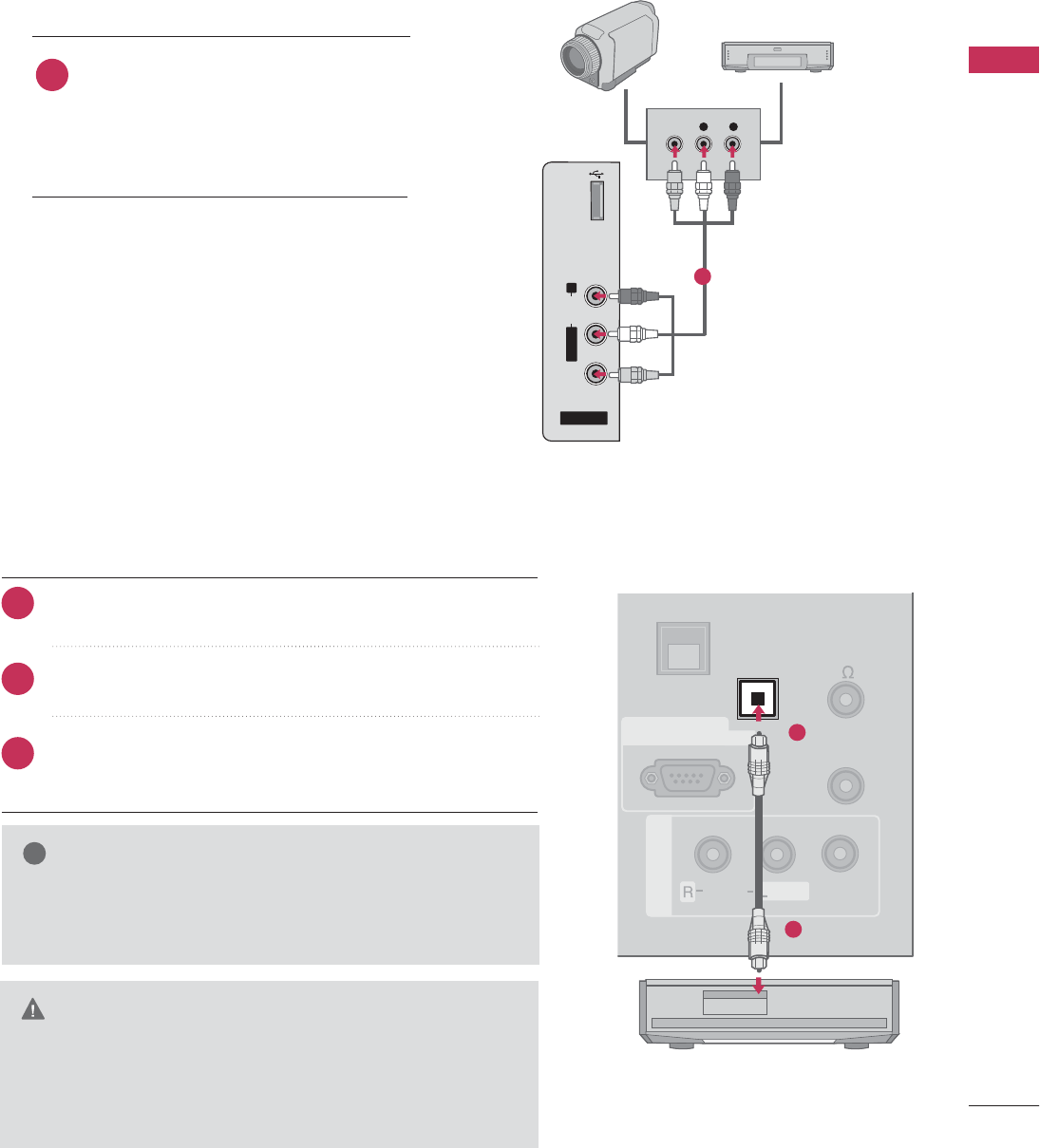
OTHER A/V SOURCE SETUP
AV IN 2
L/MONO
R
AUDIO
VIDEO
USB IN
L R
VIDEO
Camcorder
Video Game Set
Connect the A
AUDIO
/
VIDEO
jacks
between TV and external equipment.
Match the jack colors
.
(Video = yellow, Audio Left = white, and
Audio Right = red)
1. How to connect
2. How to use
■Select the
AV2
input source on the TV using the
INPUT
button on the remote control.
■If connected to
AV IN 1
input, select the
AV1
input source on the TV.
■Operate the corresponding external equipment.
1
1
Connect one end of the optical cable to the TV’s
OPTI-
CAL DIGITAL AUDIO OUT
.
Connect the other end of the optical cable to the digital
audio input on the audio equipment.
Set the “TV Speaker option - Off” in the AUDIO menu. (
G
p.83
). See the external audio equipment instruction manu-
al for operation.
AUDIO OUT CONNECTION
Send the TV’s audio to external audio equipment via the Audio Output port.
UPDATE
AV IN 1
AUDIO
VIDEO
/
REMOTE
CONTROL
OUT
SPEAKER
OUT
8
RS-232C IN
(SERVICE ONLY)
MONO
/
OPTICAL
DIGITAL
AUDIO OUT
GAME
CONTROL
1
2
G
G
When connecting with external audio equipment, such as
amplifiers or speakers, you can turn the TV speakers off in
the menu. (
G p.83
)
NOTE
!
GDo not look into the optical output port. Looking at the
laser beam may damage your vision.
G
Audio with ACP(Audio Copy Protection) function my
block digital audio output.
CAUTION
1. How to connect
2
3
1
EXTERNAL EQUIPMENT SETUP
40
EXTERNAL EQUIPMENT SETUP
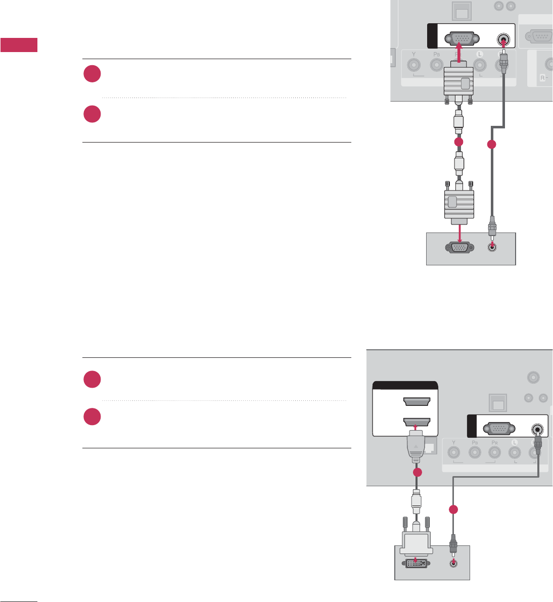
PC SETUP
This TV provides Plug and Play capability, meaning that the PC adjusts automatically to the TV's settings.
VGA (D-Sub 15 pin) Connection
UPDATE
RESET
()
COMPONENT IN
VIDEO
AUDIO
AV IN 1
A
U
RS-232C I
N
(SERVICE ONL
Y
AUDIO
RGB OUTPUT
RGB(PC)
AUDIO
(RGB/DVI)
RGB IN
12
2. How to use
■Turn on the PC and the TV.
■Select the R
RGB-PC
input source on the TV using the
INPUT
button on the remote control.
Connect the VGA output of the PC to the
RGB (P C)
jack on the TV.
Connect the PC audio output to the
AUDIO (RGB/DVI)
jack on the TV.
1. How to connect
2
1
DVI to HDMI Connection
U
P
RESET
LAN
(SERVICE ONLY)
RJP
INTERFACE
COMPONENT IN
VIDEO
AUDIO
(
S
HDMI/DVI IN
2
1(DVI)
DVI-PC OUTPUT AUDIO
RGB(PC)
AUDIO
(RGB/DVI)
RGB IN
TV-LINK
CFG
1
2
2. How to use
■Turn on the PC and the TV.
■Select the H
HDMI1
input source on the TV using the
INPUT
button on the remote control.
Connect the DVI output of the PC to the
HDMI/DVI IN
1 (DVI)
jack on the TV.
Connect the PC audio output to the
AUDIO (RGB/DVI)
jack on the TV.
1. How to connect
2
1
EXTERNAL EQUIPMENT SETUP
41
G
To get the best picture quality, adjust the PC
graphics card to
1360x768
(32/37/42LG710H, 32LD650H, 32LD655H,
32LD660H, 32LD665H, 32LV555H) or
1920x1080
(37/42/47/55LD650H,
37/42LD655H, 37/42LD660H, 37/42LD665H,
37/42/47/55LV555H).
G
Depending on the graphics card, DOS mode may
not work if a HDMI to DVI Cable is in use.
G
In PC mode, there may be noise associated with
the resolution, vertical pattern, contrast or bright-
ness. If noise is present, change the PC output to
another resolution, change the refresh rate to
another rate or adjust the brightness and contrast
on the PICTURE menu until the picture is clear.
When you use too long RGB-PC cable, there might
be a noise on the screen.
G
Avoid keeping a fixed image on the screen for a
long period of time. The fixed image could become
permanently imprinted on the screen.
G
The synchronization input form for Horizontal and
Vertical frequencies is separate.
G
Depending on the graphics card, some resolution
settings may not allow the image to be positioned
on the screen properly.
NOTES
!
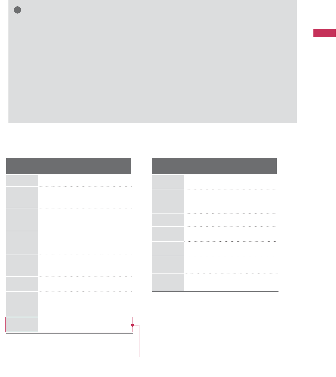
Supported Display Specifications
Resolution
720x400
1360x768
640x480
800x600
1024x768
1280x768
1280x1024
1920x1080
Horizontal Vertical
Frequency(kHz)Frequency(Hz)
31.469 70.08
31.469 59.94
37.861 72.80
37.879 60.31
48.077 72.18
48.363 60.00
56.476 70.06
47.776 59.870
60.289 74.893
47.712 60.015
63.981 60.020
79.976 75.025
66.587 59.934
HDMI-PCRGB-PC
Resolution
720x400
1360x768
800x600
1024x768
1280x768
1280x1024
Horizontal Vertical
Frequency(kHz)Frequency(Hz)
31.469 70.08
35.156 56.25
37.879 60.31
48.363 60.00
47.776 59.87
47.712 60.015
63.981 60.02
67.500 60.000
1920x1080
For 37/42/47/55LD650H, 37/42LD655H,
37/42LD660H, 37/42LD665H,
37/42/47/55LV555H
EXTERNAL EQUIPMENT SETUP
42
EXTERNAL EQUIPMENT SETUP
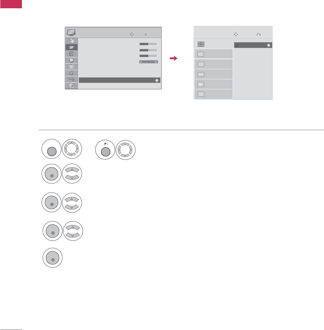
Screen Setup for PC mode
Selecting Resolution
When using RGB-PC input, change the resolution in the menus to match the PC’s.
The
Position
,
Phase
, and
Size
can also be adjusted.
Select
PICTURE
.
Select
Resolution
.
1
MENU
3
ENTER
4
Select
Screen (RGB-PC)
.
2
ENTER
5
Select the desired resolution.
ENTER
ENTER
Auto Config.
Resolution
Position
Size
Phase
Reset
SCREEN
Move
Prev.
Enter
Move
PICTURE
E
RG
• Brightness 50
• Sharpness 50
• Color 50
• Tint 0
• Advanced Control
• Picture Reset
Screen (RGB-PC)
1024 x 768
1280 x 768
1360 x 768
Home
or
EXTERNAL EQUIPMENT SETUP
43
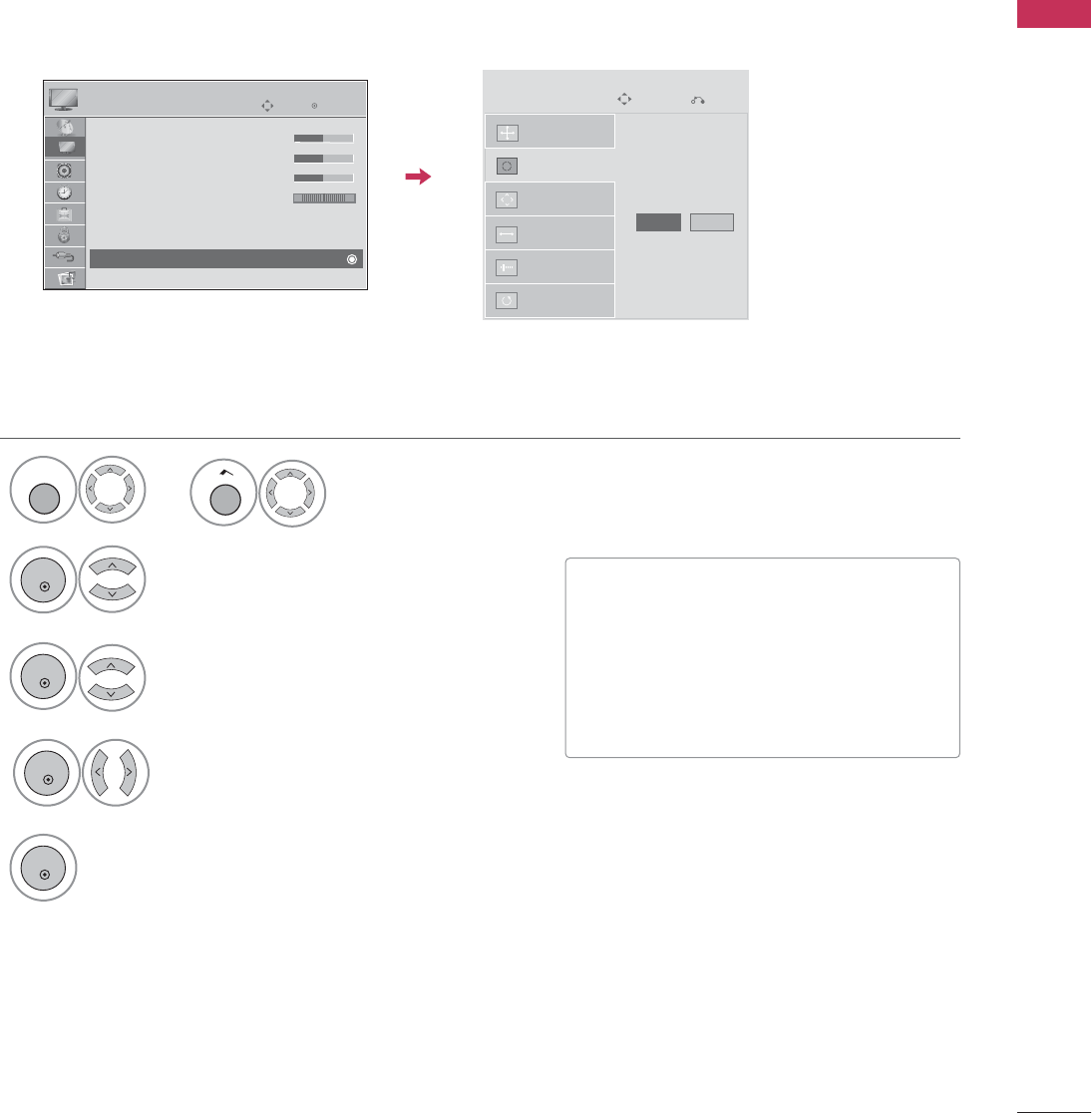
Auto Configure
Automatically adjusts picture position and minimizes image instability. After adjustment, if the image is still
not correct, try using the manual settings or a different resolution or refresh rate on the PC.
• If the position of the image is still not
correct, try Auto adjustment again.
• If picture needs to be adjusted again
after Auto adjustment in RGB-PC, you
can adjust the
Po si t i o n
,
Si z e
or
Phase
.
Select
Auto config.
.
3
ENTER
4
Select
Screen (RGB-PC)
.
2
ENTER
5
ENTER
Start Auto Configuration.
Select
Yes
.
ENTER
Auto Config.
Resolution
Position
Size
Phase
Reset
SCREEN
Move
Prev.
To Set
Yes No
Enter
Move
PICTURE
E
RG
• Brightness 50
• Sharpness 50
• Color 50
• Tint 0
• Advanced Control
• Picture Reset
Screen (RGB-PC)
Select
PICTURE
.
1
MENU
Home
or
44
EXTERNAL EQUIPMENT SETUP
EXTERNAL EQUIPMENT SETUP
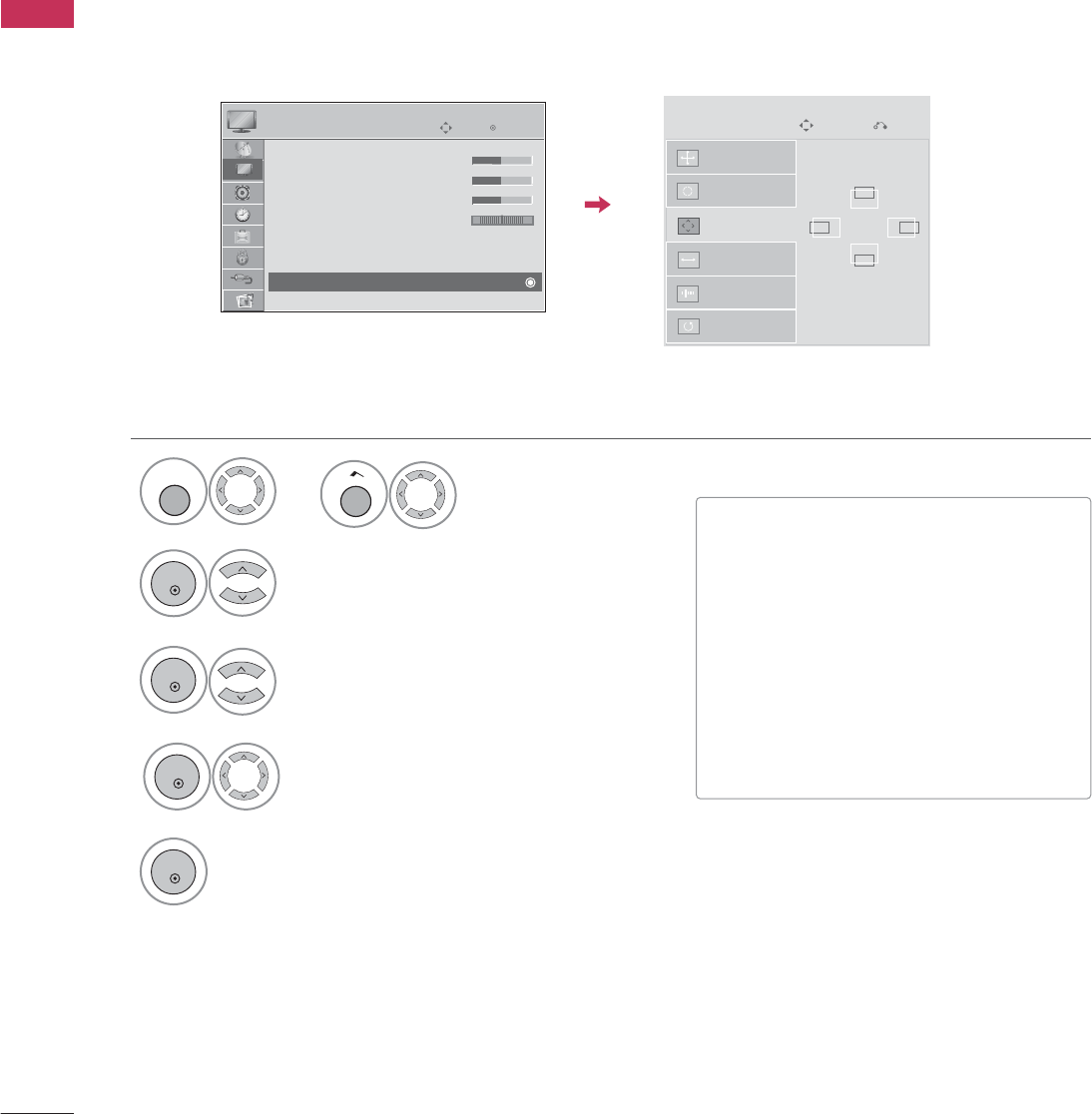
Adjustment for screen Position, Size, and Phase
If the picture is not clear after auto adjustment and especially if characters are still trembling, adjust the picture
phase manually.
This feature operates only in RGB-PC mode.
■
Position
: This function is to adjust pic-
ture to left/right and up/down as you
prefer.
■
Size
: This function is to minimize any
vertical bars or stripes visible on the
screen background. And the horizontal
screen size will also change.
■
Phase
: This function allows you to
remove any horizontal noise and clear or
sharpen the image of characters.
Select
Position
,
Size
, or
Phase
.
3
ENTER
4
Select
Screen (RGB-PC)
.
2
ENTER
5
ENTER
Make appropriate adjustments.
ENTER
Auto Config.
Resolution
Position
Size
Phase
Reset
GF
D
E
SCREEN
Move
Prev.
Enter
Move
PICTURE
E
RG
• Brightness 50
• Sharpness 50
• Color 50
• Tint 0
• Advanced Control
• Picture Reset
Screen (RGB-PC)
Select
PICTURE
.
1
MENU
Home
or
EXTERNAL EQUIPMENT SETUP
45
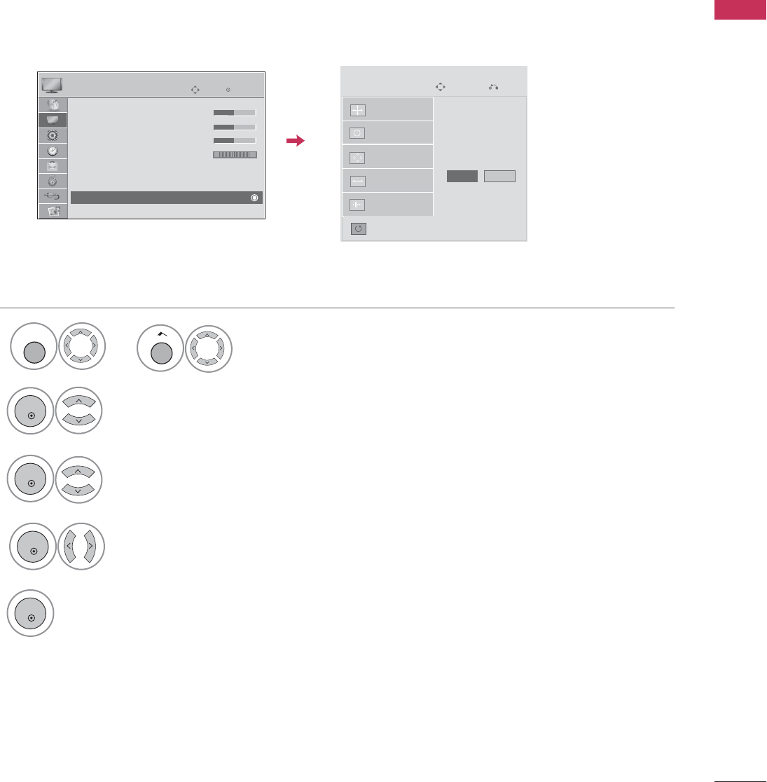
Screen Reset (Reset to original factory values)
Returns
Position
,
Size
, and
Phase
to the default factory settings.
This feature operates only in RGB-PC mode.
Select
Reset
.
3
ENTER
4
Select
Screen (RGB-PC)
.
2
ENTER
5
ENTER
Select
Yes
.
ENTER
Auto config.
Position
Resolution
Size
Phase
Reset
SCREEN
Move
Prev.
To Set
Yes No
Enter
Move
PICTURE
E
RG
• Brightness 50
• Sharpness 50
• Color 50
• Tint 0
• Advanced Control
• Picture Reset
Screen (RGB-PC)
Select
PICTURE
.
1
MENU
Home
or
WATCHING TV / CHANNEL CONTROL
46
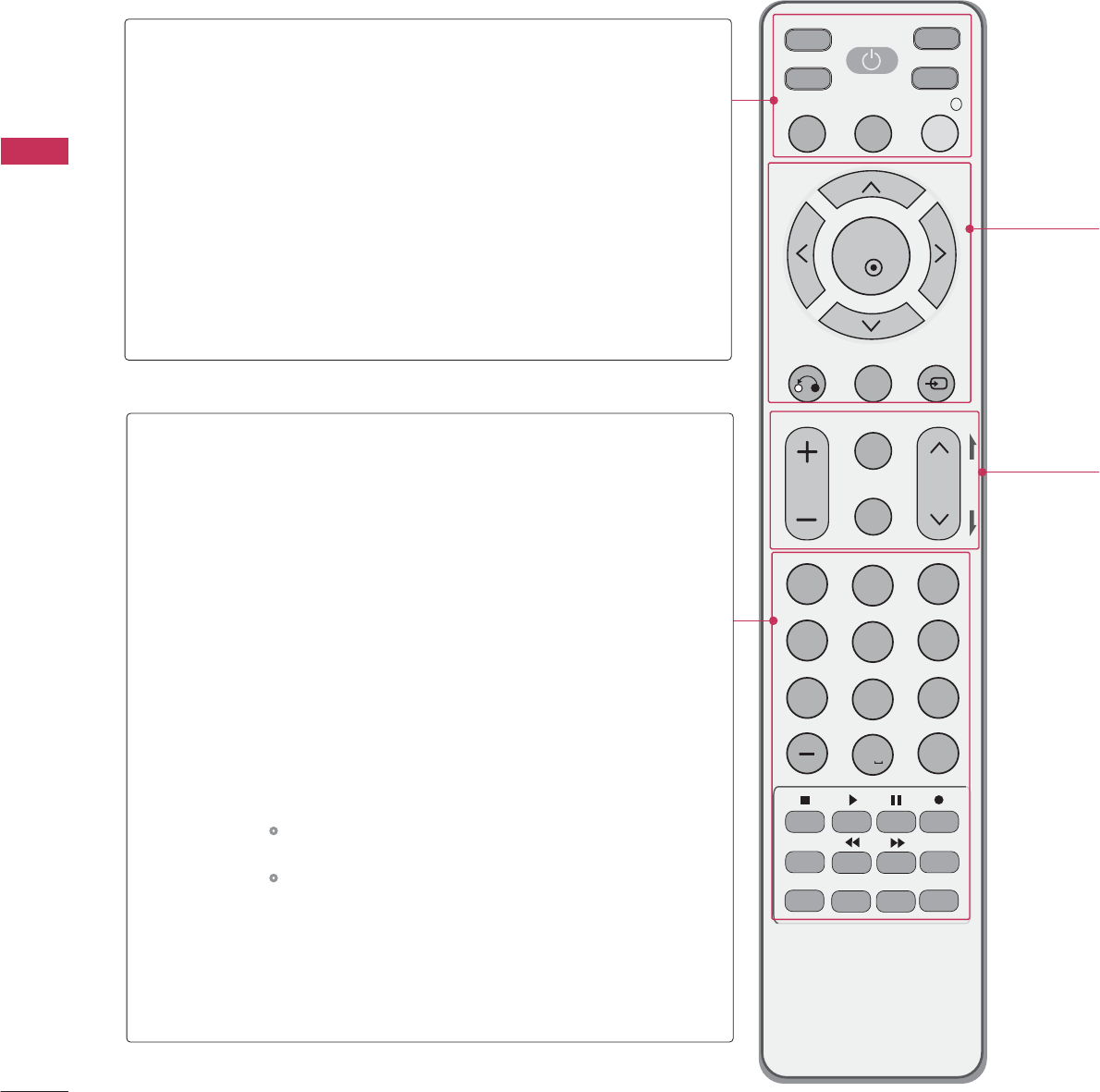
REMOTE CONTROL FUNCTIONS
When using the remote control, aim it at the remote control sensor on the TV.
MUTE
RETURN
CC
TV
POWER
GUIDE
PORTAL
ENTER
VOL CH
123
456
78
0
9
FLASHBK
VCR
DVD
INPUT
MENU
INFO
i
STB
P
A
G
E
PIP SAP
PIP CH- PIP CH+
PIP SWAP
PIP INPUT
ALPHA/NUM
REMOVE
RATIO
TIMER
ABC DEF
GHI
WXYZ
TUV
PQRS
MNO
JKL
&@
.:/,
POWER
TV/STB/DVD/VCR
GUIDE
PORTAL
INFO
Turns your TV or any other programmed equipment on
or off, depending on mode.
Selects the remote’s operating mode: TV, STB, DVD, or
VCR.
Displays and removes the electronic channel guide.
This key works only in GEM or Flash environment.
Displays and removes the hotel interactive menu.
This key works only in GEM or Flash environment.
Displays information about the selected or current events.
This key works only in GEM or Flash environment.
NUMBER
button
— (DASH)
FLASHBK
VCR/DVD/USB
control buttons
PIP
RATIO
TIMER
SAP
PIP CH +/-
PIP SWAP
PIP INPUT
Enters channel numbers or other numbers required. Also
supports characters.
Selects a program number for multiple program channels
such as 2-1, 2-2, etc.
Tunes to the last channel or input viewed.
Controls video cassette recorders or DVD players or USB.
Toggles through picture-in-picture options.
Changes the aspect ratio.
Gp.68
Turns the TV off in a set amount o f time.
Gp.94
Analog mode: Selects MTS sound (Mono, Stereo, or a
SAP)
Gp.85
DTV mode: Changes the audio language.
Changes the PIP channel.
Exchanges the main/sub images.
Selects the connected input source for the sub-picture.
WATCHING TV / CHANNEL CONTROL
WATCHING TV / CHANNEL CONTROL
47
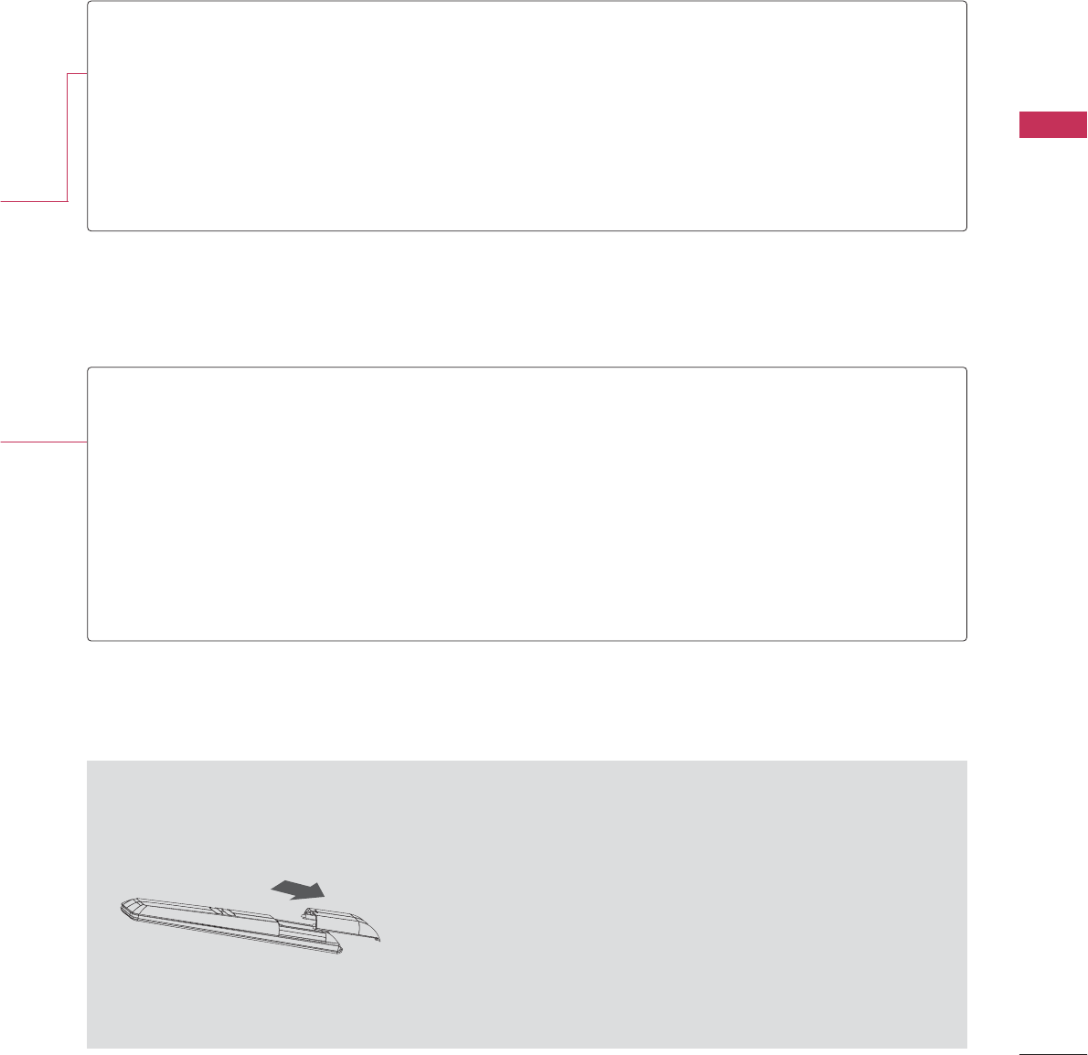
Installing Batteries
■
Open the battery compartment cover on the back side and install
the batteries with the correct polarity (+with +,-with -).
■
Install two 1.5V AAA batteries. Don’t mix old or used batteries with
new ones.
■
Close cover.
THUMBSTICK
(Up/Down/Left
Right/ENTER)
RETURN
MENU
INPUT
Navigates the on-screen menus and adjusts the system settings to your preference.
Clears all on-screen displays and returns to TV viewing from any menu.
Displays the main menu.
Rotates through inputs.
Also switches the TV on from standby.
VOLUME UP
/DOWN
CC
MUTE
CHANNEL
UP/DOWN
PAGE
UP/DOWN
Adjusts the volume.
Selects a closed caption.
Gp.88
Switches the sound on or off.
Gp.50
Selects available channels.
Moves from one full set of screen information to the next one.
WATCHING TV / CHANNEL CONTROL
48
WATCHING TV / CHANNEL CONTROL
NOTE
!
G
If you intend to be away on vacation, disconnect the power plug from the wall power outlet.
Press the
CH(
or
)
or
NUMBER
buttons to select a channel number.
1
VOLUME ADJUSTMENT
CHANNEL SELECTION
Press the
VOL (+
or
-)
button to adjust the volume.
If you want to switch the sound off, press the
MUTE
button.
You can cancel the Mute function by pressing the
MUTE
or
VOL (+
or
-)
button.
Adjust the volume to suit your personal preference.
1
2
3
TURNING ON THE TV
First, connect the power cord correctly.
At this moment, the TV switches to standby mode.
■In standby mode to turn TV on, press the button on the TV or press
the
POWER
button on the remote control.
Select the viewing source by using the
INPUT
button on the remote control.
When finished using the TV, press the
POWER
button on the remote control.
The TV reverts to standby mode.
1
2
3
WATCHING TV / CHANNEL CONTROL
49
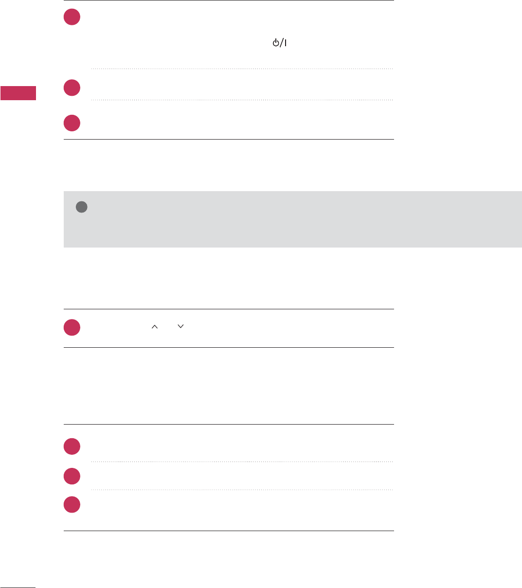
ON-SCREEN MENUS SELECTION
Your TV's OSD (On Screen Display) may differ slightly from that shown in this manual.
Display each menu.
Select a menu item.
Accept the current selection.
1
MENU
3
2
ENTER
ENTER
Return to TV viewing.
4
MENU
NOTE
!
GInfinite Sound
: For 32/37/42/47/55LD650H,
32/37/42LD655H, 32/37/42LD660H,
32/37/42LD665H, 32/37/42/47/55LV555H
G
Data Broadcasting: For 32/37/42LG710H,
32/37/42/47/55LD650H, 32/37/42LD655H
G
Zone: For 32/37/42LD660H,
32/37/42LD665H, 32/37/42/47/55LV555H
Home
or
Home
or
Enter
Move
Auto Tuning
Manual Tuning
Channel Edit
Channel Label
CHANNEL
CHANNEL
OPTION
PICTURE
LOCK
AUDIO
INPUT
TIME
USB
Enter
Move
Auto Volume : On
Clear Voice II : On
• Level 3
Balance 0
Sound Mode : Standard
•
SRS TruSurround XT:
Off
• Treble 50
• Bass 50
AUDIO
E
Enter
Move
Clock
Off Time : Off
On Time : Off
Sleep Timer : Off
Auto Off : On
TIME
Enter
Move
Photo List
Music List
Extra Contents
Eject
USB
Enter
Move
TV
AV1
AV2
Component
RGB-PC
HDMI1
HDMI2
INPUT
Enter
Move
Lock System : Off
Set Password
Block Channel
Movie Rating
TV Rating-Children
TV Rating-General
Downloadable Rating
Input Block
LOCK
Enter
Move
Menu Language : English
Audio Language : English
Caption : Off
Set ID : 1
Demo Mode : Off
Data Broadcasting
Zone
OPTION
LR
-+
Enter
Move
Aspect Ratio : 16:9
Picture Mode : Standard
• BackLight 90
• Contrast 90
• Brightness 50
• Sharpness 60
• Color 60
• Tint 0
PICTURE
E
For USA For CANADA
Lock System : Off
Set Password
Block Channel
TV Rating-English
TV Rating-French
Downloadable Rating
Input Block
WATCHING TV / CHANNEL CONTROL
50
WATCHING TV / CHANNEL CONTROL
Enter
Move
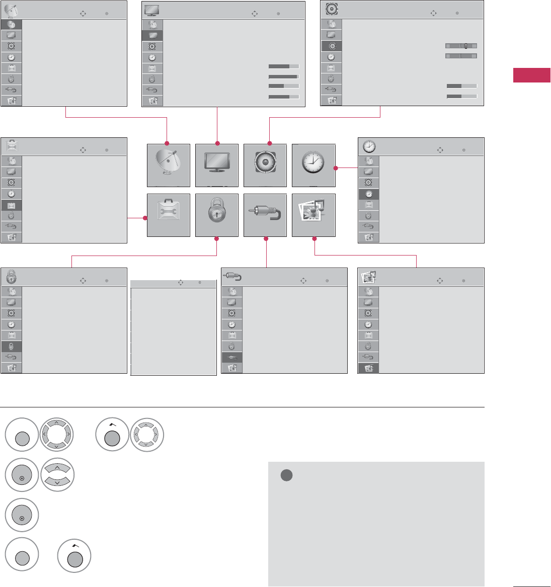
CHANNEL
Auto Scan (Auto Tuning)
Automatically finds all channels available through antenna or cable inputs and stores them in memory on the
channel list.
Run Auto Tuning again after any Antenna/Cable connection changes.
Select C
CHANNEL
.
Select
Auto Tuning
.
Select
Yes
.
Run
Auto tuning
.
1
MENU
3
2
ENTER
ENTER
4
ENTER
■A password is required to gain access to
Auto Tuning menu if the Lock System is
turned on.
5
RETURN
Return to the previous menu.
MENU
Return to TV viewing.
CHANNEL SETUP
Auto Tuning
Manual Tuning
Channel Edit
Channel Label
Enter
Move
CHANNEL
Auto Tuning
Manual Tuning
Channel Edit
Channel Label
Check your antenna connection.
The previous channel information
will be updated during Auto
Tuning.
Yes
No
Home
or
Home
or
WATCHING TV / CHANNEL CONTROL
51
2
ENTER
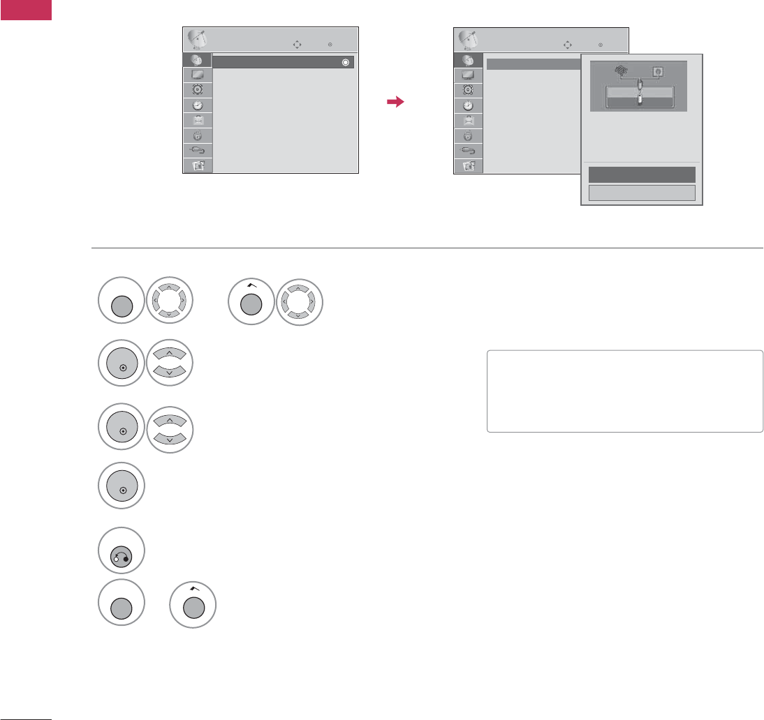
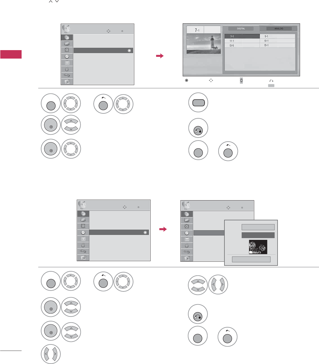
If selecting DIGITAL input signal, you can view the on-screen signal strength monitor to see the quality of the
signal being received.
Add/Delete Channel (Manual Tuning)
Select
Manual Tuning
.
Select
DIGITAL
or
ANALOG
.
Select channel you want to add
or delete.
3
ENTER
4
Select
Add
or
Delete
.
5
ENTER
■A password is required to gain access to
Manual Tuning menu if the Lock System
is turned on.
6
RETURN
Return to the previous menu.
Enter
Move
CHANNEL
Enter
Move
CHANNEL
Channel
Select channel type and
RF-channel number.
F
DIGITAL
G
2
Close
Delete
DIGITAL 2-1
Bad Normal Good
Auto Tuning
Manual Tuning
Channel Edit
Channel Label
Auto Tuning
Manual Tuning
Channel Edit
Channel Label
Select
CHANNEL
.
1
MENU
Home
or
MENU
Return to TV viewing.
Home
or
WATCHING TV / CHANNEL CONTROL
52
WATCHING TV / CHANNEL CONTROL
CHANNEL LABEL
Select a channel.
Select channel you want to add or delete.
3
ENTER
4
The channels in the Channel Edit List are displayed in black and the channels deleted from the Channel Edit
List are displayed in blue. When a channel number is deleted, it means that you will be unable to select it using
CH
button during TV viewing.
If you wish to select the deleted channel, directly enter the channel number with the NUMBER buttons or select
it in the
Channel Edit
menu.
Channel Editing
2
ENTER
Select
Channel Edit
.Return to the previous menu.
5
RETURN
Choose preset labels for your channels.
If a channel label is provided on the signal from the broadcasting station, the TV displays a short name for a
channel even if you didn't preset a label for the channel.
Select
Channel Label
.
Select a Channel.
3
2
ENTER
ENTER
Select the appropriate logo for the
channel.
5
Select a channel to set logo.
4
6
RETURN
Return to the previous menu.
Enter
Move
CHANNEL
Auto Tuning
Manual Tuning
Channel Edit
Channel Label
Ch. Change Page Change
CH
Navigation Previous
Add/Delete
Enter
Move
CHANNEL
Auto Tuning
Manual Tuning
Channel Edit
Channel Label
Enter
Move
CHANNEL
Auto Tuning
Manual Tuning
Channel Edit
Channel Label Logo
F
Disney
G
Channel ANALOG 2-0
Close
Select
CHANNEL
.
1
MENU
Home
or
Select
CHANNEL
.
1
MENU
Home
or
MENU
Return to TV viewing.
Home
or
MENU
Return to TV viewing.
Home
or
WATCHING TV / CHANNEL CONTROL
53
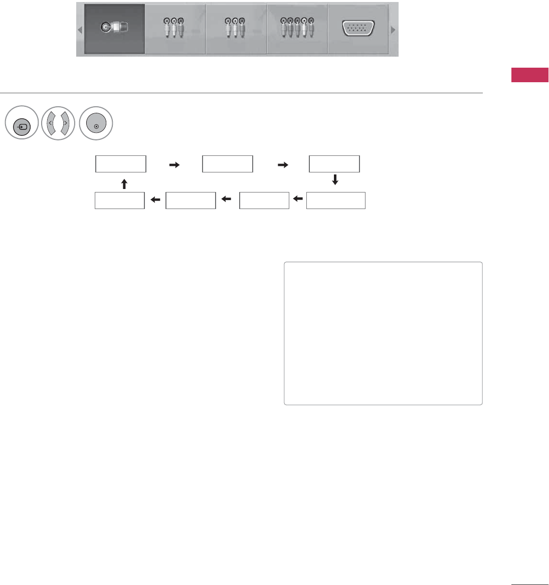
INPUT LIST
Select the desired input source.
1
INPUT
TV AV1 AV2
ComponentHDMI1 RGB-PC
TV AV1 AV2 Component RGB-PC
ENTER
■
T V
: Select it to watch over-the-air, cable
and digital cable broadcasts.
■
AV1-2
: Select them to watch a VCR or
other external equipment.
■
Component
: Select them to watch
DVD or a Digital set-top box.
■
RGB-PC
: Select it to view PC input.
■
HDMI1-2
: Select them to watch high
definition devices.
HDMI2
WATCHING TV / CHANNEL CONTROL
54
WATCHING TV / CHANNEL CONTROL
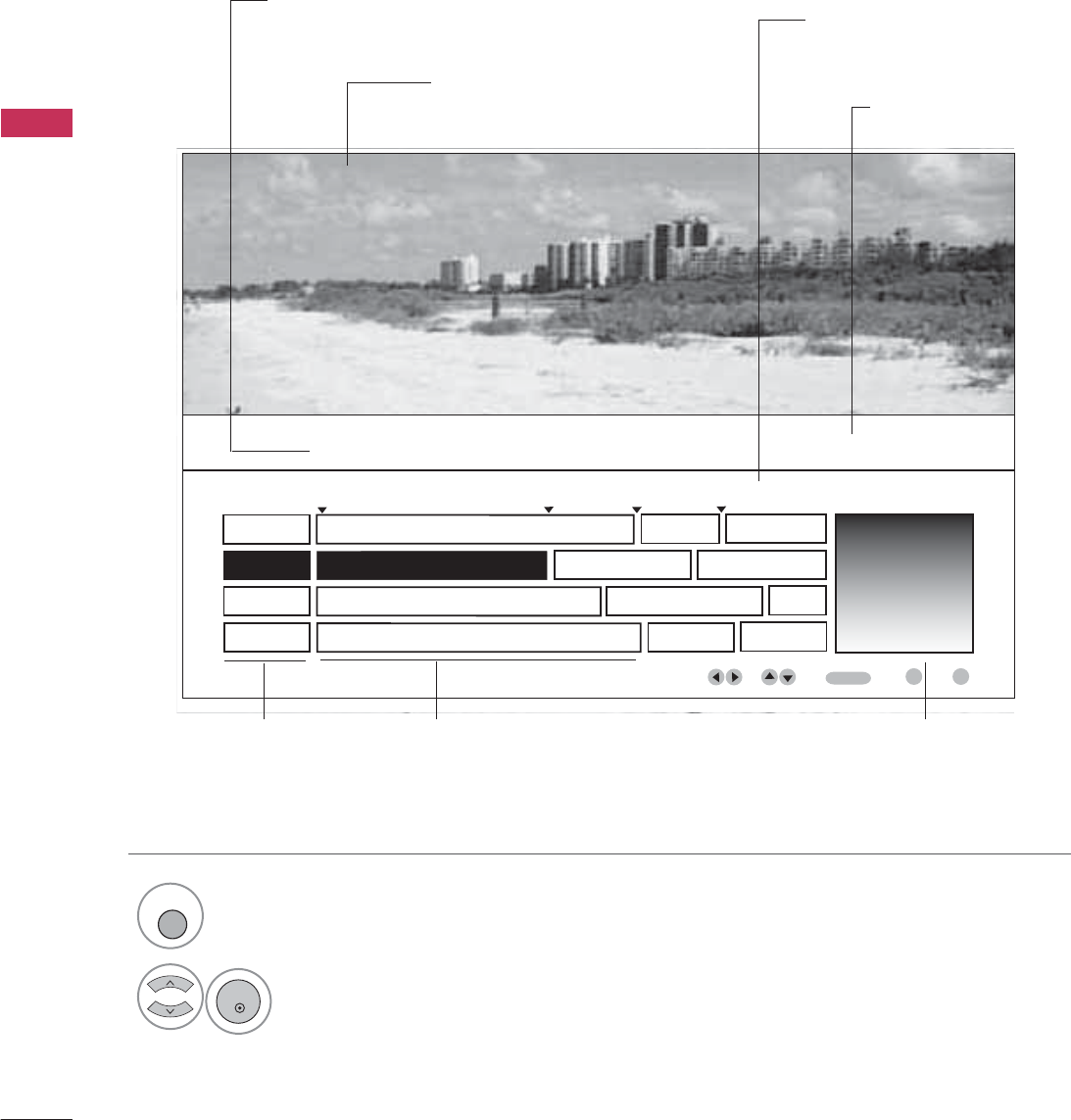
EXAMPLE ELECTRONIC PROGRAM GUIDE
This is an example of a typical TV electronic program guide showing available programming.
On The Political Scene
Kids Movies
Top Fashions
World Events Today
Channel 01:30 AM 2:30 AM 2:45 AM 3:00 AM
Kids ... Kids ...
Kids Movies
K&M
17 XYZ
18 K&M
19 PQX
20 WBD
Mon. 29 May 2009 11:07
New Release
Greatest Hits
Kids
EVENT
CHANNEL
SELECTION
PORTAL
INFO
ENTER
PROGRAMMING GRID
Program listings arranged in
time slots.
CHANNEL LIST
Shows available
channels in numerical
order.
DATE/TIME OSD
Shows current Date/Time.
CHANNEL INDICATOR
Currently tuned channel
and program.
PROGRAM TITLES
Highlight a title and press
Enter to display additional
program information.
FEATURED ATTRACTION
Highlight and click to get
expanded information.
TV PROGRAM
Current program on select-
ed channel.
Select
GUIDE
button to shows available TV programs.
1
GUIDE
Select a Channel.
2
ENTER
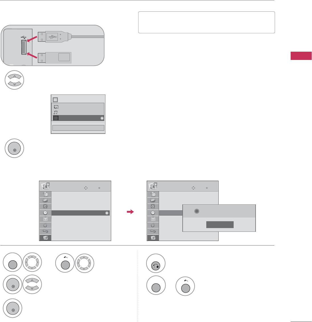
USB
55
USB IN
R
Memory Key
Connect the USB device to the
USB IN
jack
on the side of TV.
3
Select
PHOTO LIST
or
MUSIC LIST
or
EXTRA CONTENTS
.
1
2
■This TV supports playback of JPG pictures and MP3
audio.
When you connect a USB device, this pop-up menu is displayed automatically.
When the Pop-Up menu does not appear, you can select Photo List or Music List on Extra contents.
On a USB device, you can not add a new folder or delete an existing folder.
or
ENTRY MODES
ENTER
■
Image shown may differ from your TV.
Close
Choose the media you want.
Fl
i
Photo List
Music List
Extra Contents
USB
Enter
Move
USB
Select U
USB
.
Select
Eject
.
1
MENU
3
2
ENTER
ENTER
4
RETURN
Return to the previous menu.
When removing the USB device
Photo List
Music List
Extra Contents
Eject
Enter
Move
USB
Photo List
Music List
Extra Contents
Eject
Close
Now you can eject USB.
i
MENU
Return to TV viewing.
Home
or
Home
or

USB
56
USB
Precautions with USB devices.
G
Only a USB storage device is recognizable.
G
If the USB storage device is connected through a USB hub, the device is not recognizable.
G
A USB storage device using an automatic recognition program may not be recognized.
G
A USB storage device which uses its own driver may not be recognized.
G
The recognition speed of a USB storage device may depend on each device.
G
In case of a card reader, up to four memory cards are concurrently recognizable.
G
Please do not turn off the TV or unplug the USB device when the connected USB storage device is working.
When such device is suddenly separated or unplugged, the stored files or the USB storage device may be dam-
aged.
G
Only use a USB storage device which has normal music, image or movie files.
G
Please connect power to a USB storage device (over 0.4A) which requires an external power supply. If not, the
device may not be recognized.
G
Please connect a USB storage device with cable is offered by USB maker. If connected with cable is not offered
by USB maker or an excessively long cable, the device may not be recognized.
G
Some USB storage devices may not be supported or operate properly.
G
File alignment method of USB storage device is similar to Window XP and filename can recognize up to 100
English characters.
G
Please backup important files because data on the USB device may be damaged. Data management is the con-
sumer's responsibility and as a result, the manufacturer does not cover data damage.
G
Please use only a USB storage device which was formatted as a FAT32, NTFS file system provided with the Windows
operating system. In case of a storage device formatted as a different utility programme which is not supported by
Windows, it may not be recognized.
G
Data in a USB storage device cannot be deleted in the NTFS file system.
G
If your USB memory device has multiple partitions, or if you use a USB multi-card reader, you can use up to 4
partitions or USB memory devices.
G
The recommended capacity is 1TB or less for a USB external hard disk and 32GB or less for USB memory.
G
Any device with more than the recommended capacity may not work properly.
G
When using a USB HDD via the USB extensing cable, connect a support electric power source.
USB
57
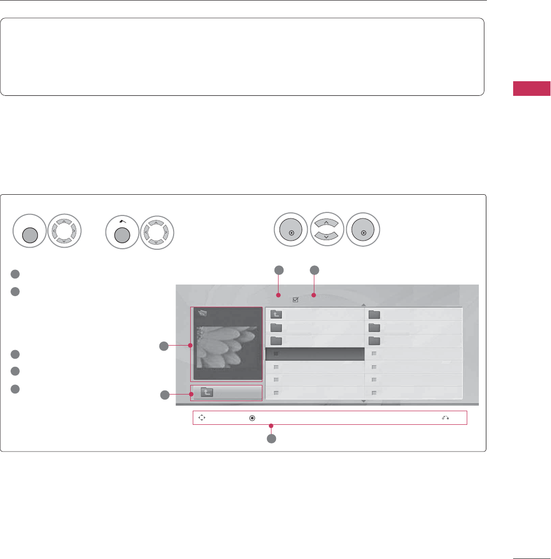
PHOTO LIST
This TV only supports picture in JPEG(.jpg) format.
The On-Screen Display on your model may be slightly different.
Screen Components
Moves to upper level folder
Preview: Displays the
thumbnail/folder name of
the photo in the selected
folder
Current page/Total pages
Total number of marked photos
Corresponding buttons on
the remote control
Select
Photo List
.
2
1
2
3
4
5
Navigation Popup Menu Exit
5
Page 2/3 No Marked
Photo List
Up Folder
1366x768, 125KB
KY101 06/10/2008
KY102 04/03/2008
JMJ001 01/01/2000
JMJ002 06/15/2008
JMJ003 04/03/2008
JMJ004 02/18/2008
KY103 03/30/2008
KY104 06/19/2008
KY105 01/31/2008
JMJ005 05/13/2008
JMJ006 05/26/2008
JMJ007 02/18/2008
JMJ008 02/18/2008
Up Folder
Drive1
JMJ001
3 4
2
1
Supported photo file: *.JPG
• You can view JPG files only.
• Only baseline scan is supported among JPG.
• Supported JPG size: 64 pixel (width) x 64 pixel (height) to 15360 pixel (width) x 8640 pixel (height)
ENTER
ENTER
Select
USB
.
1
MENU
Home
or
USB
58
USB
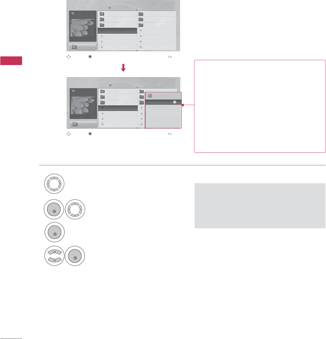
Photo Selection and Pop-up Menu
Select the target folder or drive.
Select the desired photos.
2
Show the Pop-up menu.
3
1
■When one or more photos are marked, you can
view individual photos or a slide show of the
marked photos. If no photos are marked, you
can view all photos individually or all photos in
the folder in a slide show.
4Select the desired Popup menu.
Page 2/3
No Marked
Photo List
Up Folder
1366x768, 125KB
KY101 06/10/2008
KY102 04/03/2008
JMJ001 01/01/2000
JMJ002 06/15/2008
JMJ003 04/03/2008
JMJ004 02/18/2008
KY103 03/30/2008
KY104 06/19/2008
KY105 01/31/2008
JMJ005 05/13/2008
JMJ006 05/26/2008
JMJ007 02/18/2008
JMJ008 02/18/2008
Up Folder
Page 2/3
No Marked
Photo List
Up Folder
1366x768, 125KB
KY101 06/10/2008
KY102 04/03/2008
JMJ001 01/01/2000
JMJ002 06/15/2008
JMJ003 04/03/2008
JMJ004 02/18/2008
KY103 03/30/2008
KY104 06/19/2008
KY105 01/31/2008
JMJ005 05/13/2008
JMJ006 05/26/2008
JMJ007 02/18/2008
JMJ008 02/18/2008
Up Folder
Drive1
Drive1
JMJ001
JMJ001 1366x768, 125KB
View
Mark
Mark All
Delete
Close
Navigation Exit
Popup Menu
Navigation Exit
Popup Menu
When you select a file (not folder), this Pop-Up
menu is displayed.
GView
: Display the selected item.
GMark
: Use to mark a photo.
GUnmark
: Use to unmark a photo.
GMark All
: Mark all photos on the screen.
GUnmark All
: Deselect all marked photos.
GDelete
or
Delete Marked
: Delete the selected
photo item.
GClose
: Close the pop-up menu.
ENTER
ENTER
ENTER
USB
59
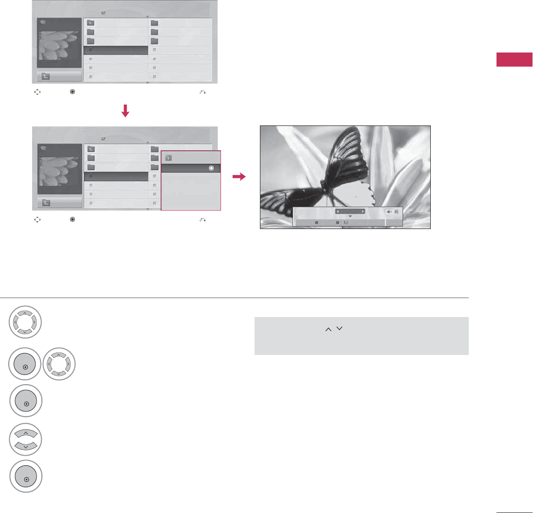
Full Screen Menu
You can change the Photo List view so that it fills the screen. More operations are available in full
screen mode.
■Use the
CH
button to navigate in the
photo page.
Select the target folder or drive.
Select the desired photos.
Show the Pop-up menu.
5
Select
View
.
The selected photo is displayed in
full size.
2
3
1
4
Page 2/3
No Marked
Photo List
Up Folder
1366x768, 125KB
KY101 06/10/2008
KY102 04/03/2008
JMJ001 01/01/2000
JMJ002 06/15/2008
JMJ003 04/03/2008
JMJ004 02/18/2008
KY103 03/30/2008
KY104 06/19/2008
KY105 01/31/2008
JMJ005 05/13/2008
JMJ006 05/26/2008
JMJ007 02/18/2008
JMJ008 02/18/2008
Up Folder
Page 2/3
No Marked
Photo List
Up Folder
1366x768, 125KB
KY101 06/10/2008
KY102 04/03/2008
JMJ001 01/01/2000
JMJ002 06/15/2008
JMJ003 04/03/2008
JMJ004 02/18/2008
KY103 03/30/2008
KY104 06/19/2008
KY105 01/31/2008
JMJ005 05/13/2008
JMJ006 05/26/2008
JMJ007 02/18/2008
JMJ008 02/18/2008
Up Folder
Drive1
Drive1
JMJ001
JMJ001
Navigation Exit
Popup Menu
Navigation Exit
Popup Menu
The aspect ratio of a photo may change the size of the
photo displayed on the screen in full size.
Press the
RETURN
button to move to the previous menu
screen.
1/17
Slideshow BGM Delete Option Hide
1366x768, 125KB
View
Mark
Mark All
Delete
Close
ENTER
ENTER
ENTER
USB
60
USB
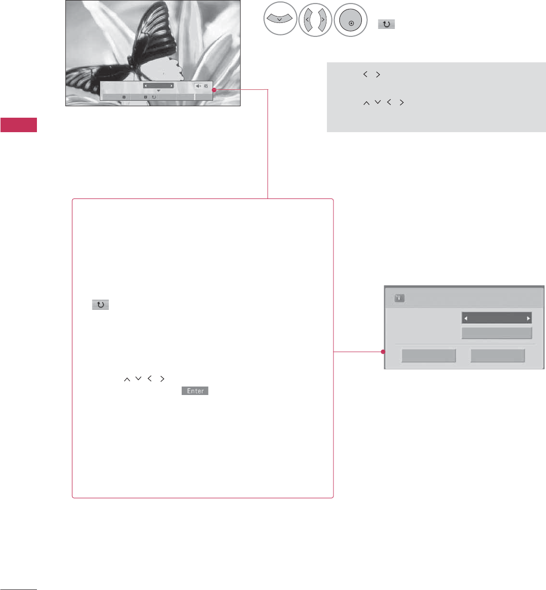
Press
F G
to set the time interval between slides.
Slide Speed Fast
Cancel
...
Music Album
Enter
Select the
Slideshow
,
BGM
,
(Rotate)
,
Delete
,
Option
,
or
Hide.
■Use button to select the previous or
next photo.
■Use button to select and control
the menu on the full-sized screen.
6
1/17
Slideshow BGM Delete Option Hide
GSlideshow
: Selected photos are displayed during the
slide show. If no photo is selected, all photos in the cur-
rent folder are displayed during slide show.
■Set the time interval of the slide show in
Option
.
GBGM
: Listen to music while viewing photos in full size.
■Set the BGM device and album in
Option
.
G(Rotate)
: Rotate photos.
■Rotates the photo 90°, 18 0 °, 270°, 360°clockwise.
GDelete
: Delete photos.
GOption
: Set values for
Slide Speed
and
Music
Album
.
■Use button and
ENTER
button to set
values. Then go to and press
ENTER
to save
the settings.
■You cannot change
Music Album
while BGM is
playing.
GHide
: Hide the menu on the full-sized screen.
■To see the menu again on the full-sized screen, press
ENTER
button to display.
ENTER
USB
61
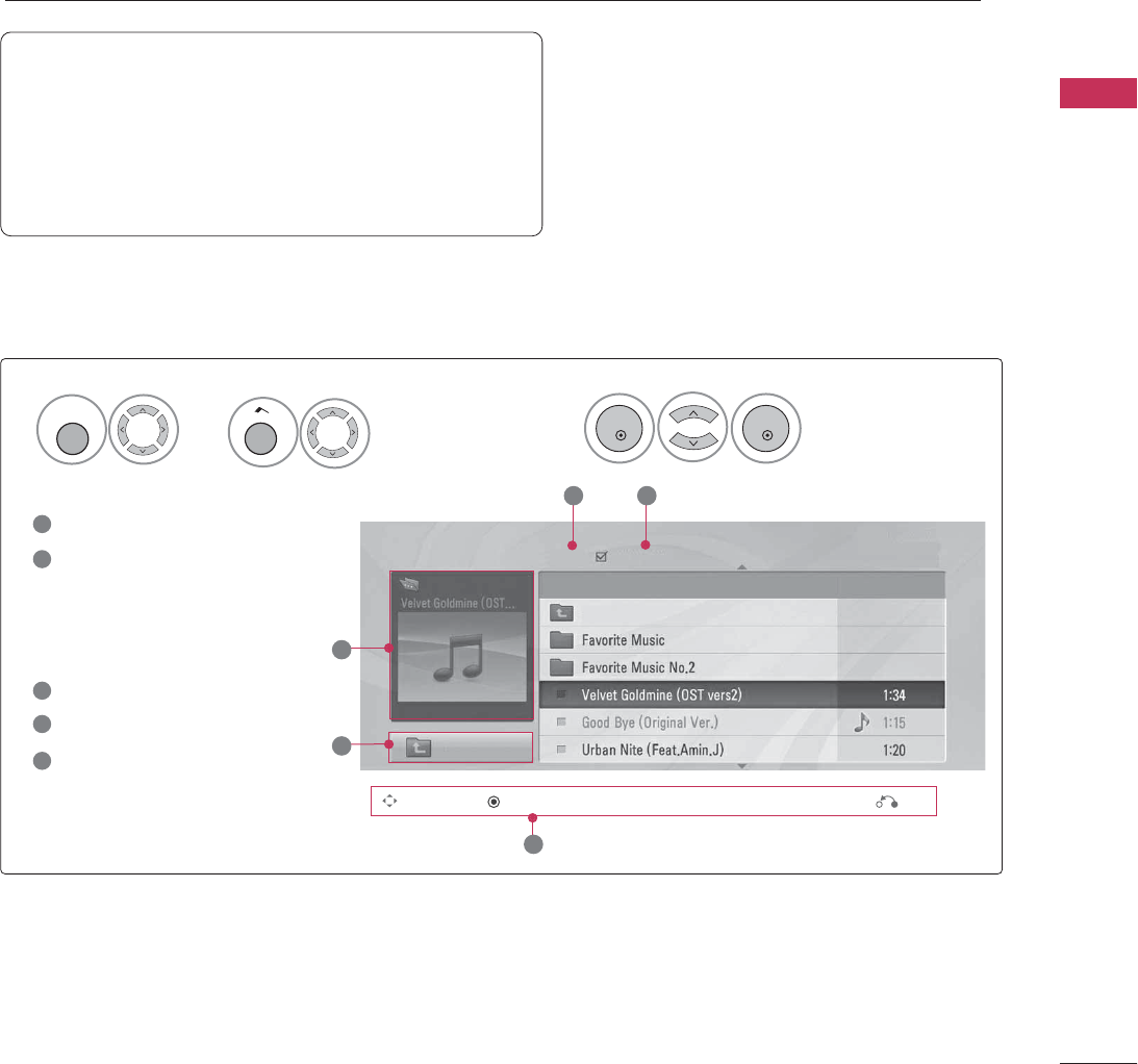
MUSIC LIST
You can use the Music List menu to play MP3 files from a USB storage device.
This TV cannot play back copy-protected files.
The On-Screen Display on your model may be slightly different.
Screen Components
Moves to upper level folder
Preview: If a supported pic-
ture of the album jacket is
in the file, it will be dis-
played here.
Current page/Total pages
Total number of marked files
Corresponding buttons on
the remote control
1
3
4
5
2
Select
Music List
.
2
Music List
Up Folder
Title Duration
3 4
2
1
Page 2/3 No Marked
Drive1
Navigation Popup Menu Exit
5
A
00:00 / 04:16
Up Folder
Supported music file: *.MP3
Bit rate range 32 Kbps - 320 Kbps
• Sampling rate (Sampling Frequency)
MPEG1 layer 3: 32 kHz, 44.1 kHz, 48 kHz
MPEG2 layer 3: 16 kHz, 22.05 kHz, 24 kHz
MPEG2.5 layer 3: 8 kHz, 11.025 kHz, 12 kHz
ENTER
ENTER
Select
USB
.
1
MENU
Home
or
USB
62
USB
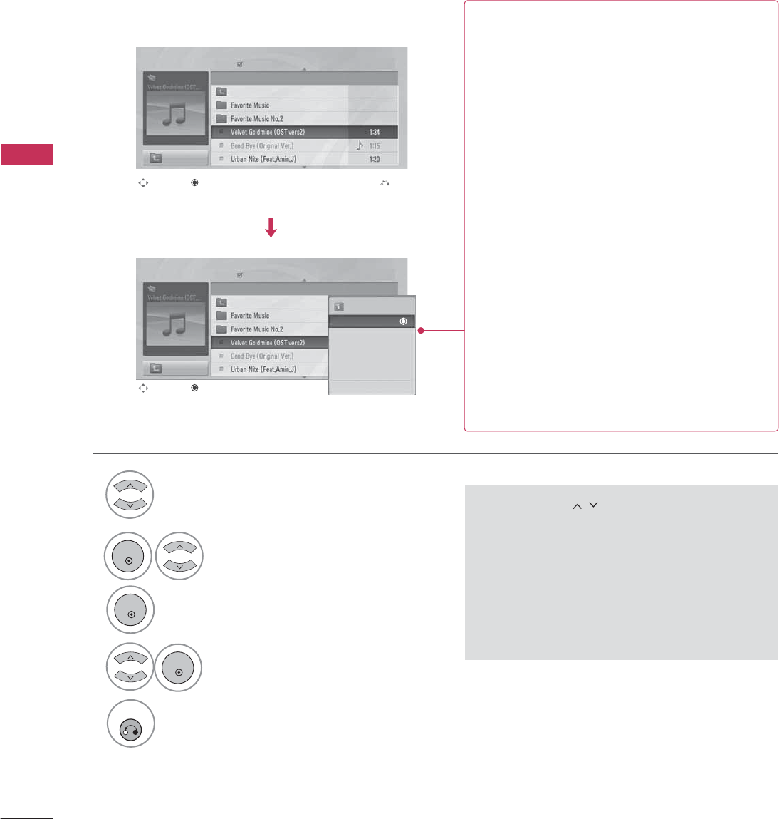
Music Selection and Pop-up Menu
■Use the
CH
button to navigate in the
music page.
■If no music is marked, all the music in the fold-
er will be played in sequence. When one or
more music files are marked, the marked music
files will be played in sequence. If you want to
listen to only one song repeatedly, just mark
that one file and play.
Select the target folder or drive.
Select the desired musics.
Show the Pop-up menu.
Select the desired Pop-up menu.
2
3
1
4
5
RETURN
Return to TV viewing.
Navigation Exit
Popup Menu
Navigation Popup Menu
Page 2/3
No Marked
Music List
Up Folder
A
00:00 / 04:16
Up Folder
Drive1 Title
Duration
Page 2/3
No Marked
Music List
Up Folder
A
00:00 / 04:16
Up Folder
Drive1 Title
Duration
3945 KB
128 Kbps
Play
Play with Photo
Mark
Mark All
Delete
Close
GPlay
(During stop): Play the selected file.
Once a song finishes playing, the next selected
one will be played. When there are no selected
files to play, the next one in the current folder
will be played. If you go to a different folder and
press the
ENTER
button, the current song in
playback will stop.
GPlay Marked
: Play the selected files. Once a
file finishes playing, the next selected one will
be played automatically.
GStop Play
(During playback): Stop the play-
ing files.
GPlay with Photo
: Start playing the selected
files and then move to the Photo List.
GMark:
Use to mark a file.
GUnmark:
Use to unmark a file.
GMark All
: Mark all files in the folder.
GUnmark All
: Deselect all marked files.
GDelete
or
Delete Marked
: Delete the selected
files.
GClose
: Close the pop-up menu.
ENTER
ENTER
ENTER
USB
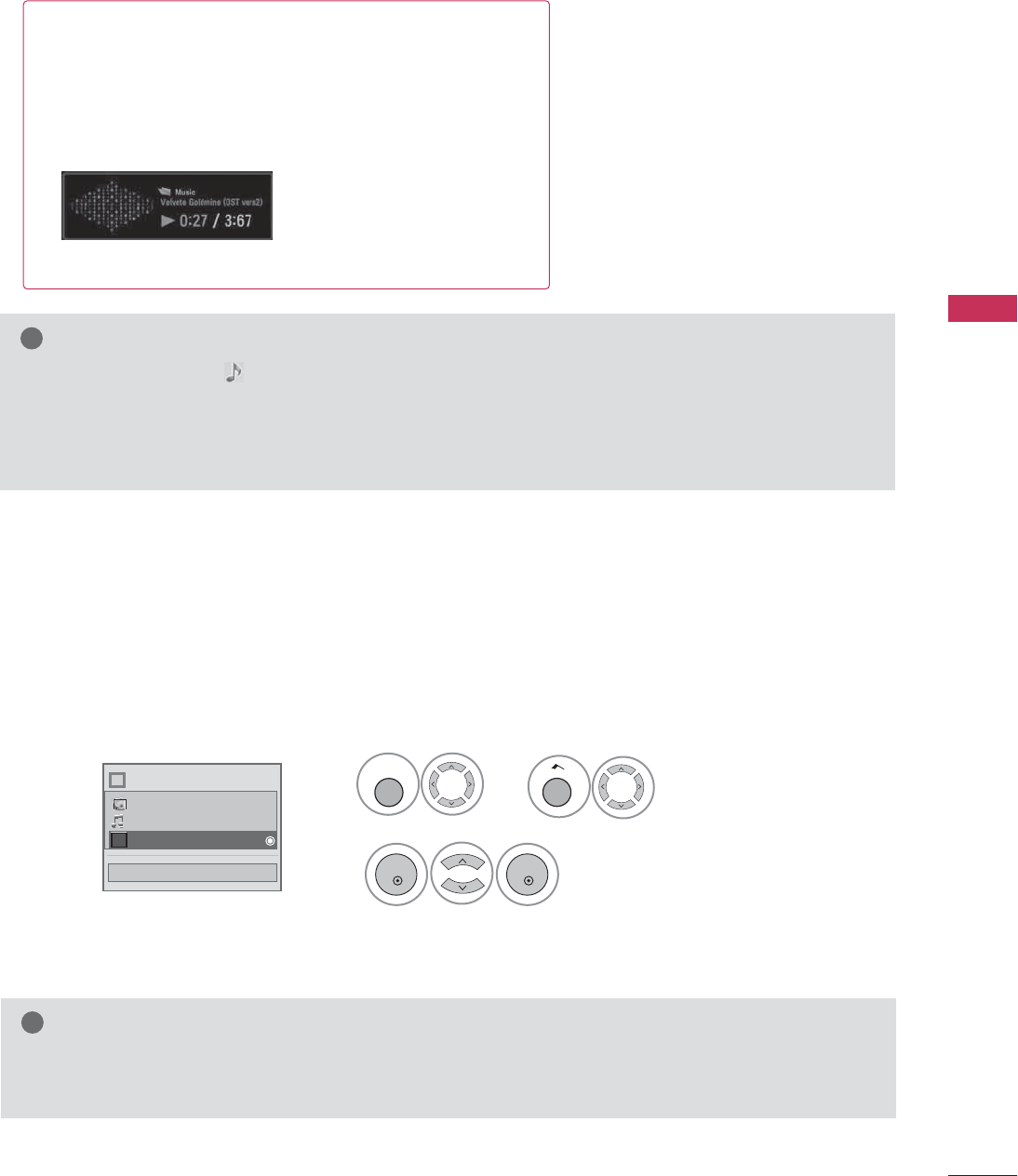
63
■The play information box (as shown below) will automatically
move across the screen when there is no user input to pre-
vent a fixed image remaining on the screen for a extended
period of time.
NOTE
!
G
When music is playing, is displayed in front of the music play time.
G
A damaged or corrupted music file that does not play displays 00:00 as the play time.
G
Files downloaded from a paid service with copyright protection are not supported and will not play.
G
Press
ENTER
,
A
or
RETURN
button to stop the screen saver.
EXTRA CONTENTS
Extra Contents will be activated when Data Channel service is available.
Select
Extra Contents
.
2
ENTER
ENTER
NOTE
!
G
Pro:Centric contents in USB memory stick can be played.
G
For more information. contact to Customer Support.(www.lgcommercial.com)
Close
Choose the media you want.
Fl
i
Photo List
Music List
Extra Contents
Select
USB
.
1
MENU
Home
or

PICTURE CONTROL
64
PICTURE CONTROL
PIP (PICTURE-IN-PICTURE)
PIP enables the end user to view two sources on the screen at the same time. The end user can switch
between the Main and Sub picture sizes.
789
0
PQRS TUV WXYZ
PIP CH- PIP CH+ PIP SWAP PIP INPUT
PIP SAP
FLASHBK
TIMER
&@
RATIO
PIP INPUT
Selects viewing source for PIP
window.
PIP SWAP
Switches Main screen and
PIP window sources.
PIP CH+
Selects next higher channel
for PIP window.
PIP CH-
Selects next lower channel
for PIP window.
PIP Operation
1. Connect auxiliary source(s) to TV
connections panel.
2. Enter Installer menu to be sure
source(s) is enabled.
3. Use the interactive remote provided
in the room to operate PIP.
4. Press PIP on remote.
Use the PIP function keys to
operate the available PIP features.
5. To exit PIP mode, simply press PIP.
PIP
Turns PIP mode on and off.
■Note: Actual size of Main screen and PIP inset may be different than
shown above.