LG Electronics USA 55LV555HUA LCD TV/Monitor User Manual SAC34134301 Edit1
LG Electronics USA LCD TV/Monitor SAC34134301 Edit1
Contents
- 1. User manual 1 of 5
- 2. User manual 2 of 5
- 3. User manual 3 of 5
- 4. User manual 4 of 5
- 5. User manual 5 of 5
User manual 1 of 5

OWNER’S MANUAL
LED LCD TV / LCD TV
Please read this manual carefully before operating
your set and retain it for future reference.
P/NO : SAC34134301 (1107-REV05) www.lg.com
32LG710H
37LG710H
42LG710H
32LD650H
37LD650H
42LD650H
47LD650H
55LD650H
32LD655H
37LD655H
42LD655H
32LD660H
37LD660H
42LD660H
32LD665H
37LD665H
42LD665H
32LV555H
37LV555H
42LV555H
47LV555H
55LV555H
2
WARNING / CAUTION
WARNING / CAUTION
To prevent fire or shock hazards, do not expose
this product to rain or moisture.
FCC NOTICE
Class B digital device
This equipment has been tested and found to comply
with the limits for a Class B digital device, pursuant to
Part 15 of the FCC Rules. These limits are designed
to provide reasonable protection against harmful
interference in a residential installation. This equipment
generates, uses and can radiate radio frequency energy
and, if not installed and used in accordance with the
instructions, may cause harmful interference to radio
communications. However, there is no guarantee that
interference will not occur in a particular installation.
If this equipment does cause harmful interference to
radio or television reception, which can be determined
by turning the equipment off and on, the user is
encouraged to try to correct the interference by one
or more of the following measures:
- Reorient or relocate the receiving antenna.
- Increase the separation between the equipment and
receiver.
- Connect the equipment to an outlet on a circuit
different from that to which the receiver is connected.
- Consult the dealer or an experienced radio/TV
technician for help.
This device complies with part 15 of the FCC Rules.
Operation is subject to the following two condi-
tions: (1) This device may not cause (harmful)
interference, and (2) this device must accept any
interference received, including interference that
may cause undesired operation (of the device).
Any changes or modifications in construction of this
device which are not expressly approved by the party
responsible for compliance could void the user’s
authority to operate the equipment.
CAUTION
Do not attempt to modify this product in any way
without written authorization from LG Electronics.
Unauthorized modification could void the user’s
authority to operate this product
WARNING
RISK OF ELECTRIC SHOCK
DO NOT OPEN
The lightning flash with arrowhead
symbol, within an equilateral triangle, is
intended to alert the user to the presence
of uninsulated “dangerous voltage” within the
product’s enclosure that may be of sufficient
magnitude to constitute a risk of electric shock to
persons.
The exclamation point within an equilateral
triangle is intended to alert the user to
the presence of important operating
and maintenance (servicing) instructions in the
literature accompanying the appliance.
TO REDUCE THE RISK OF ELECTRIC SHOCK
DO NOT REMOVE COVER (OR BACK). NO
USER SERVICEABLE PARTS INSIDE. REFER TO
QUALIFIED SERVICE PERSONNEL.
WARNING/CAUTION
TO REDUCE THE RISK OF FIRE AND ELECTRIC
SHOCK, DO NOT EXPOSE THIS PRODUCT TO
RAIN OR MOISTURE.
NOTE TO CABLE/TV INSTALLER
This reminder is provided to call the CATV system
installer’s attention to Article 820-40 of the National
Electric Code (U.S.A.). The code provides guidelines for
proper grounding and, in particular, specifies that the
cable ground shall be connected to the grounding system
of the building, as close to the point of the cable entry
as practical.
3
SAFETY INSTRUCTIONS
Read these instructions.
Keep these instructions.
Heed all warnings.
Follow all instructions.
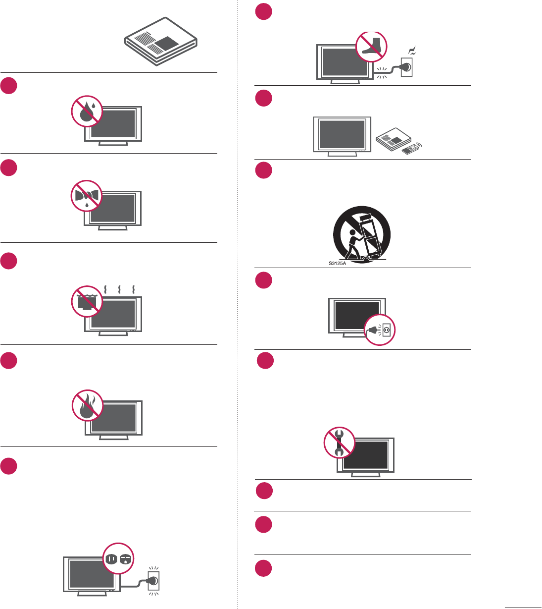
Do not use this apparatus near water.
Clean only with a dry cloth.
Do not block any ventilation openings. Install in
accordance with the manufacturer’s instructions.
Do not install near any heat sources such as radia-
tors, heat registers, stoves, or other apparatus
(including amplifiers)that produce heat.
Do not defeat the safety purpose of the polarized or
grounding-type plug. A polarized plug has two blades
with one wider than the other. A grounding type plug
has two blades and a third grounding prong, The
wide blade or the third prong are provided for your
safety. If the provided plug does not fit into your out-
let, consult an electrician for replacement of the
obsolete outlet.
Protect the power cord from being walked on or
pinched particularly at plugs, convenience recepta-
cles, and the point where they exit from the appara-
tus.
Only use attachments/accessories specified by the
manufacturer.
Use only with the cart, stand, tripod, bracket, or table
specified by the manufacturer, or sold with the appa-
ratus. When a cart is used, use caution when moving
the cart/apparatus combination to avoid injury from
tip-over.
Unplug this apparatus during lighting storms or
when unused for long periods of time.
Refer all servicing to qualified service personnel.
Servicing is required when the apparatus has been
damaged in any way, such as power-supply cord or
plug is damaged, liquid has been spilled or objects
have fallen into the apparatus, the apparatus has
been exposed to rain or moisture, does not operate
normally, or has been dropped.
Never touch this apparatus or antenna during a
thunder or lighting storm.
When mounting a TV on the wall, make sure not to
install the TV by the hanging power and signal cables
on the back of the TV.
Do not allow an impact shock or any objects to fall
into the product, and do not drop onto the screen
with something.
IMPORTANT SAFETY INSTRUCTIONS
1
2
3
4
5
7
8
9
10
11
12
13
6
4
CAUTION concerning the Power Cord :
It is recommend that appliances be placed upon a
dedicated circuit; that is, a single outlet circuit which
powers only that appliance and has no additional
outlets or branch circuits. Check the specification
page of this owner's manual to be certain.
Do not connect too many appliances to the same
AC power outlet as this could result in fire or elec-
tric shock.
Do not overload wall outlets. Overloaded wall out-
lets, loose or damaged wall outlets, extension cords,
frayed power cords, or damaged or cracked wire
insulation are dangerous. Any of these conditions
could result in electric shock or fire. Periodically
examine the cord of your appliance, and if its
appearance indicates damage or deterioration,
unplug it, discontinue use of the appliance, and
have the cord replaced with an exact replacement
part by an authorized servicer. Protect the power
cord from physical or mechanical abuse, such as
being twisted, kinked, pinched, closed in a door, or
walked upon. Pay particular attention to plugs, wall
outlets, and the point where the cord exits the
appliance.
Do not make the TV with the power cord plugged
in. Do not use a damaged or loose power cord. Be
sure do grasp the plug when unplugging the power
cord. Do not pull on the power cord to unplug the
TV.
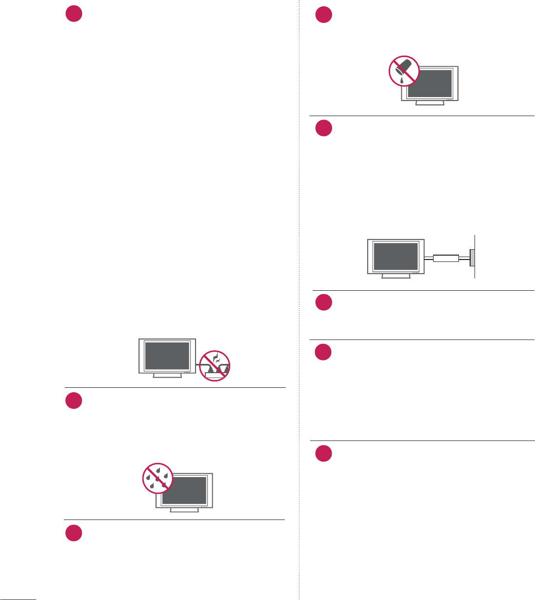
WARNING - To reduce the risk of fire or electrical
shock, do not expose this product to rain, moisture
or other liquids. Do not touch the TV with wet
hands. Do not install this product near flammable
objects such as gasoline or candles or expose the
TV to direct air conditioning.
As long as this unit is connected to the AC wall out-
let, it is not disconnected from the AC power
source even if you turn off this unit by SWITCH.
Do not expose to dripping or splashing and do not
place objects filled with liquids, such as vases, cups,
etc. on or over the apparatus (e.g. on shelves above
the unit).
GROUNDING
Ensure that you connect the earth ground wire to
prevent possible electric shock. (i.e. a TV with a
three-prong grounded AC plug must be connected
to a three-prong grouned AC outlet) If grounding
methods are not possible, have a qualified electri-
cian install a separate circuit breaker.
Do not try to ground the unit by connecting it to
telephone wires, lightening rods, or gas pipes.
DISCONNECTING DEVICE FROM MAINS
Mains plug is the disconnecting device. The plug
must remain readily operable.
Dot Defect
The Plasma or LCD panel is a high technology
product with resolution of two million to six million
pixels. In a very few cases, you could see fine dots
on the screen while you’re viewing the TV. Those
dots are deactivated pixels and do not affect the
performance and reliability of the TV.
Generated Sound
“Cracking” noise: A cracking noise that occurs
when watching or turning off the TV is generated
by plastic thermal contraction due to tempera-
ture and humidity. This noise is common for prod-
ucts where thermal deformation is required.
Electrical circuit humming/panel buzzing: A low
level noise is generated from a high-speed switch-
ing circuit, which supplies a large amount of cur-
rent to operate a product. It varies depending
on the product.
This generated sound does not affect the per-
formance and reliability of the product.
14 17
18
19
Power
Supply
Short-circuit
Breaker
20
15
16
21
5
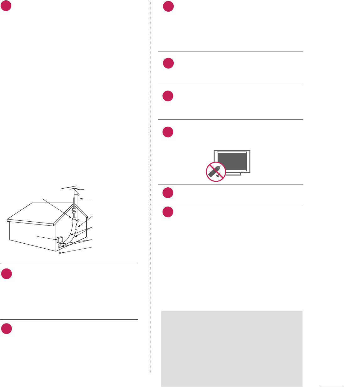
ANTENNAS
Outdoor antenna grounding
If an outdoor antenna is installed, follow the precau-
tions below. An outdoor antenna system should not
be located in the vicinity of overhead power lines or
other electric light or power circuits, or where it can
come in contact with such power lines or circuits as
death or serious injury can occur.
Be sure the antenna system is grounded so as to pro-
vide some protection against voltage surges and
built-up static charges.
Section 810 of the National Electrical Code (NEC) in
the U.S.A. provides information with respect to prop-
er grounding of the mast and supporting structure,
grounding of the lead-in wire to an antenna dis-
charge unit, size of grounding conductors, location of
antenna discharge unit, connection to grounding
electrodes and requirements for the grounding elec-
trode.
Antenna grounding according to the
National Electrical Code, ANSI/NFPA 70
Cleaning
When cleaning, unplug the power cord and scrub
gently with a soft cloth to prevent scratching. Do not
spray water or other liquids directly on the TV as
electric shock may occur. Do not clean with chemi-
cals such as alcohol, thinners or benzene.
Moving
Make sure the product is turned off, unplugged
and all cables have been removed. It may take 2 or
more people to carry larger TVs. Do not press
against or put stress on the front panel of the TV.
Ventilation
Install your TV where there is proper ventilation. Do
not install in a confined space such as a bookcase.
Do not cover the product with cloth or other mate-
rials (e.g.) plastic while plugged in. Do not install in
excessively dusty places.
Take care not to touch the ventilation openings.
When watching the TV for a long period, the venti-
lation openings may become hot.
If you smell smoke or other odors coming from the
TV, unplug the power cord contact and authorized
service center.
Do not press strongly upon the panel with a hand or
sharp object such as nail, pencil or pen, or make a
scratch on it.
Keep the product away from direct sunlight.
For LCD TV
If the TV feels cold to the touch, there may be
a small “flicker” when it is turned on. This is
normal, there is nothing wrong with TV.
Some minute dot defects may be visible on the
screen, appearing as tiny red, green, or blue
spots. However, they have no adverse effect on
the monitor's performance.
Avoid touching the LCD screen or holding your
finger(s) against it for long periods of time.
Doing so may produce some temporary dis-
tortion effects on the screen.
24
22
Antenna Lead in Wire
Antenna Discharge Unit
(NEC Section 810-20)
Grounding Conductor
(NEC Section 810-21)
Ground Clamps
Power Service Grounding
Electrode System (NEC
Art 250, Part H)
Ground Clamp
Electric Service
Equipment
NEC: National Electrical Code
25
26
27
28
23
ON DISPOSAL
(Only Hg lamp used LCD TV)
The fluorescent lamp used in this product contains
a small amount of mercury. Do not dispose of
this product with general household waste.
Disposal of this product must be carried out in
accordance to the regulations of your local authority.
29
30

6
CONTENTS
WARNING / CAUTION
. . . . . . . . . . . . . . . . . . . . . . . . . . . . 2
SAFETY INSTRUCTIONS
. . . . . . . . . . . . . . . . . . . . . . . . . . 3
FEATURES OF THIS TV
. . . . . . . . . . . . . . . . . . . . . . . . . . . . . 8
PREPARATION
Accessories . . . . . . . . . . . . . . . . . . . . . . . . . . . . . . . . . . . . . . . . . . . . . . . . . . . . . . 9
Front Panel Information . . . . . . . . . . . . . . . . . . . . . . . . . . . . . . . . . . . . 12
Back Panel Information . . . . . . . . . . . . . . . . . . . . . . . . . . . . . . . . . . . . 15
Stand Instructions . . . . . . . . . . . . . . . . . . . . . . . . . . . . . . . . . . . . . . . . . . . 19
Cable Management . . . . . . . . . . . . . . . . . . . . . . . . . . . . . . . . . . . . . . . . . 23
Desktop Pedestal Installation . . . . . . . . . . . . . . . . . . . . . . . . . . . 26
Swivel Stand . . . . . . . . . . . . . . . . . . . . . . . . . . . . . . . . . . . . . . . . . . . . . . . . . . . 26
Attaching the TV to a desk . . . . . . . . . . . . . . . . . . . . . . . . . . . . . . 27
VESA Wall Mounting . . . . . . . . . . . . . . . . . . . . . . . . . . . . . . . . . . . . . . . . 29
Securing the TV to the wall to prevent falling
When the TV is used on a stand
. . . . . . . . . . . . . . . . . . . . . . . . . . 31
Antenna or Cable Connection . . . . . . . . . . . . . . . . . . . . . . . . . . 32
MPI Card Slot / PPV Card Installation . . . . . . . . . . . . . . 33
EXTERNAL EQUIPMENT SETUP
HD Receiver Setup . . . . . . . . . . . . . . . . . . . . . . . . . . . . . . . . . . . . . . . . . . 34
DVD Setup . . . . . . . . . . . . . . . . . . . . . . . . . . . . . . . . . . . . . . . . . . . . . . . . . . . . . 37
VCR Setup . . . . . . . . . . . . . . . . . . . . . . . . . . . . . . . . . . . . . . . . . . . . . . . . . . . . . 38
Other A/V Source Setup . . . . . . . . . . . . . . . . . . . . . . . . . . . . . . . . . 39
Audio Out Connection . . . . . . . . . . . . . . . . . . . . . . . . . . . . . . . . . . . . 39
PC Setup . . . . . . . . . . . . . . . . . . . . . . . . . . . . . . . . . . . . . . . . . . . . . . . . . . . . . . . . 40
WATCHING TV / CHANNEL CONTROL
Remote Control Functions . . . . . . . . . . . . . . . . . . . . . . . . . . . . . . . 46
Turning On The TV . . . . . . . . . . . . . . . . . . . . . . . . . . . . . . . . . . . . . . . . . 50
Channel Selection . . . . . . . . . . . . . . . . . . . . . . . . . . . . . . . . . . . . . . . . . . . 50
Volume Adjustment . . . . . . . . . . . . . . . . . . . . . . . . . . . . . . . . . . . . . . . . . 50
On-Screen Menus Selection . . . . . . . . . . . . . . . . . . . . . . . . . . . . . 51
Channel Setup
- Auto Scan (Auto Tuning) . . . . . . . . . . . . . . . . . . . . . . . . . . . 52
- Add / Delete Channel (Manual Tuning) . . . . . . 53
- Channel Editing . . . . . . . . . . . . . . . . . . . . . . . . . . . . . . . . . . . . . . . . 54
Channel Label . . . . . . . . . . . . . . . . . . . . . . . . . . . . . . . . . . . . . . . . . . . . . . . . . 54
Input List . . . . . . . . . . . . . . . . . . . . . . . . . . . . . . . . . . . . . . . . . . . . . . . . . . . . . . . . 55
Example Electronic Program Guide . . . . . . . . . . . . . . . . . . . 56
USB
Entry Modes . . . . . . . . . . . . . . . . . . . . . . . . . . . . . . . . . . . . . . . . . . . . . . . . . . . 57
Photo List . . . . . . . . . . . . . . . . . . . . . . . . . . . . . . . . . . . . . . . . . . . . . . . . . . . . . . . 59
Music List . . . . . . . . . . . . . . . . . . . . . . . . . . . . . . . . . . . . . . . . . . . . . . . . . . . . . . . 63
Extra Contents . . . . . . . . . . . . . . . . . . . . . . . . . . . . . . . . . . . . . . . . . . . . . . . . 65
PICTURE CONTROL
PIP (Picture-In-Picture) . . . . . . . . . . . . . . . . . . . . . . . . . . . . . . . . . . . . 66
Picture Size (Aspect Ratio) Control . . . . . . . . . . . . . . . . . . 68
Preset Picture Settings (Picture Mode) . . . . . . . . . . . . . 71
Manual Picture Adjustment - User Mode . . . . . . . . . . 72
Picture Improvement Technology . . . . . . . . . . . . . . . . . . . . . 73
Picture Reset . . . . . . . . . . . . . . . . . . . . . . . . . . . . . . . . . . . . . . . . . . . . . . . . . . 75
Demo mode . . . . . . . . . . . . . . . . . . . . . . . . . . . . . . . . . . . . . . . . . . . . . . . . . . . . 76
SOUND & LANGUAGE CONTROL
Auto Volume Leveler (Auto Volume) . . . . . . . . . . . . . . . . . 77
Preset Sound Settings (Sound Mode) . . . . . . . . . . . . . . . 78
Sound Setting Adjustment - User Mode . . . . . . . . . . . 79
- SRS TruSurround XT . . . . . . . . . . . . . . . . . . . . . . . . . . . . . . . . . 80
- Infinite Sound . . . . . . . . . . . . . . . . . . . . . . . . . . . . . . . . . . . . . . . . . . . 80
Clear Voice ll . . . . . . . . . . . . . . . . . . . . . . . . . . . . . . . . . . . . . . . . . . . . . . . . . . . 81
Balance . . . . . . . . . . . . . . . . . . . . . . . . . . . . . . . . . . . . . . . . . . . . . . . . . . . . . . . . . . 82
TV Speakers On/Off Setup . . . . . . . . . . . . . . . . . . . . . . . . . . . . . . 83
Audio Reset . . . . . . . . . . . . . . . . . . . . . . . . . . . . . . . . . . . . . . . . . . . . . . . . . . . 84
Stereo/SAP Broadcast Setup . . . . . . . . . . . . . . . . . . . . . . . . . . . 85
Audio Language . . . . . . . . . . . . . . . . . . . . . . . . . . . . . . . . . . . . . . . . . . . . . . 86
On-Screen Menus Language Selection . . . . . . . . . . . . . . 87
Caption Mode
- Analog Broadcasting System Captions . . . . . . . 88
- Digital Broadcasting System Captions . . . . . . . . 89
- Caption Option . . . . . . . . . . . . . . . . . . . . . . . . . . . . . . . . . . . . . . . 90

7
TIME SETTING
Clock Setting
- Auto Clock Setup . . . . . . . . . . . . . . . . . . . . . . . . . . . . . . . . . . . . . 91
- Manual Clock Setup . . . . . . . . . . . . . . . . . . . . . . . . . . . . . . . . . 92
Auto On/Off Time Setting . . . . . . . . . . . . . . . . . . . . . . . . . . . . . . 93
Sleep Timer Setting . . . . . . . . . . . . . . . . . . . . . . . . . . . . . . . . . . . . . . . . . 94
Auto Shut-Off Setting . . . . . . . . . . . . . . . . . . . . . . . . . . . . . . . . . . . . . . 94
PARENTAL CONTROL / RATINGS
Set Password & Lock System . . . . . . . . . . . . . . . . . . . . . . . . . . . 95
Channel Blocking . . . . . . . . . . . . . . . . . . . . . . . . . . . . . . . . . . . . . . . . . . . . 98
Movie & TV Rating . . . . . . . . . . . . . . . . . . . . . . . . . . . . . . . . . . . . . . . . . 99
Downloadable Rating . . . . . . . . . . . . . . . . . . . . . . . . . . . . . . . . . . . . . 10 4
External Input Blocking . . . . . . . . . . . . . . . . . . . . . . . . . . . . . . . . . . 105
APPENDIX
Troubleshooting . . . . . . . . . . . . . . . . . . . . . . . . . . . . . . . . . . . . . . . . . . . . 10 6
Maintenance . . . . . . . . . . . . . . . . . . . . . . . . . . . . . . . . . . . . . . . . . . . . . . . . . 108
Product Specifications . . . . . . . . . . . . . . . . . . . . . . . . . . . . . . . . . . . 109
Programming the Remote Control . . . . . . . . . . . . . . . . . . . 112
IR Codes . . . . . . . . . . . . . . . . . . . . . . . . . . . . . . . . . . . . . . . . . . . . . . . . . . . . . . . 115
Open Source License . . . . . . . . . . . . . . . . . . . . . . . . . . . . . . . . . . . . . . 117
8
FEATURES OF THIS TV
■
When a fixed image (e.g. logos, screen menus, video game, and computer display) is displayed on the TV
for an extended period, it can become permanently imprinted on the screen. This phenomenon is known
as “image burn” or “burn-in.” Image burn is not covered under the manufacturer’s warranty.
■
In order to prevent image burn, avoid displaying a fixed image on your TV screen for a prolonged period
(2 or more hours for LCD, 1 or more hours for Plasma).
■
Image burn can also occur on the letterboxed
areas of your TV if you use the 4:3 aspect
ratio setting for an extended period.
IMPORTANT INFORMATION TO PREVENT “IMAGE BURN
/ BURN-IN” ON YOUR TV SCREEN
Automatically enhances and amplifies the sound of
human voice frequency range to help keep dialogue
audible when background noise swells.
LG TV include a unique invisible speaker system,
tuned by renowned audio expert, Mr. Mark Levinson.
Speakers are embedded in strategic spots behind the
front cabinet and use minute vibrations to turn the
entire front bezel into the speaker system. The result
is a clean, polished look, and enhanced audio by
increasing the “sweet spot”, giving a wider and richer
sound field.
HDMI, the HDMI logo and High-Definition
Multimedia Interface are trademarks or registered
trademarks of HDMI Licensing LLC."
is a trademark of SRS Labs, Inc.
TruSurround XT technology is incorporated under
license from SRS Labs, Inc.
Manufactured under license from Dolby Laboratories.
“
Dolby
“and the double-D symbol are trademarks of
Dolby Laboratories.
High-definition television. High-resolution digital
television broadcast and playback system composed
of roughly a million or more pixels, 16:9 aspect-ratio
screens, and AC3 digital audio. A subset of digital
television, HDTV formats include 1080i and 720p
resolutions.
Unlike other sensors which can only sense brightness
of ambient light, LG’s “Intelligent Sensor” uses 4,096
sensing steps to evaluate its surroundings. Using a
sophisticated algorithm, the LG processes picture
quality elements including brightness, contrast, color,
sharpness and white balance. The result is a picture
optimized for it’s surroundings, more pleasing to
watch and which can also save up to 50% in power
consumption.
Matches the original frame rate of the film for a more
film-like experience
View videos and photos and listen to music on your
TV through USB 2.0 (‘videos’ dependent on model).
■This feature is not available for all models.
PREPARATION
9
PREPARATION
ACCESSORIES
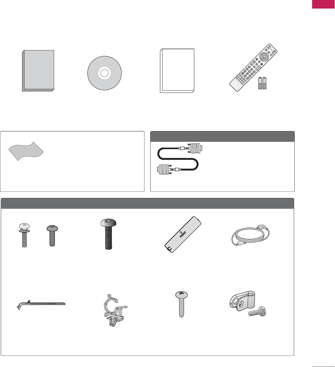
Ensure that the following accessories are included with your TV. If an accessory is missing, please contact the
dealer where you purchased the TV.
The accessories included may differ from the images below.
Quick Reference Guide
Protective bracket and
screw for power cord
(Refer to P.23)
Cable holder
(Refer to P.23)
* Wipe spots on the exterior only with
the polishing cloth.
* Do not wipe roughly when removing
stains. Excessive pressure may cause
scratches or discoloration.
Polishing Cloth
(Not included with all
models.)
Optional Extras
When using the VGA (D-sub 15-
pin signal cable) PC connection,
the user must use shielded signal
interface cables with ferrite
cores to maintain standards
compliance.
x 2
Torx plus
Star-head screw
(Refer to P.19)
Screw for
stand fixing
(Refer to P.27)
Screws for
stand assembly
(Refer to P.19)
x 4 x 4
MUTE
RETURN
CC
TV
POWER
GUIDE
PORTAL
ENTER
VOL CH
123
456
78
0
9
FLASHBK
VCR
DVD
INPUT
MENU
INFO
i
STB
P
A
G
E
PIPSAP
PIP CH- PIP CH+
PIP SWAP
PIP INPUT
ALPHA/NUM
REMOVE
RATIO
TIMER
ABC DEF
GHI
WXYZ
TUV
PQRS
MNO
JKL
&@
.:/,
1.5V 1.5V
Remote control,
batteries (AAA)
Protection cover
(Refer to P.19)
Plug-in type holder
(Refer to P.23)
F
For 32/37/42LG710H
(For 32LG710H)
Power cord
Owner’s Manual CD Manual
(For 32/37/42LG710H,
32/37/42/47/55LD650H,
32/37/42LD655H) (For 32/37/42/47/55LV555H)
D-sub 15-pin
signal cable
PREPARATION
10
PREPARATION
Power cord
Screws for
stand fixing
(Refer to P.27)
Washers for
stand fixing
(Refer to P.27)
x 2
Cable holder
(Refer to P.24)
Plug-in type holder
(Refer to P.24)
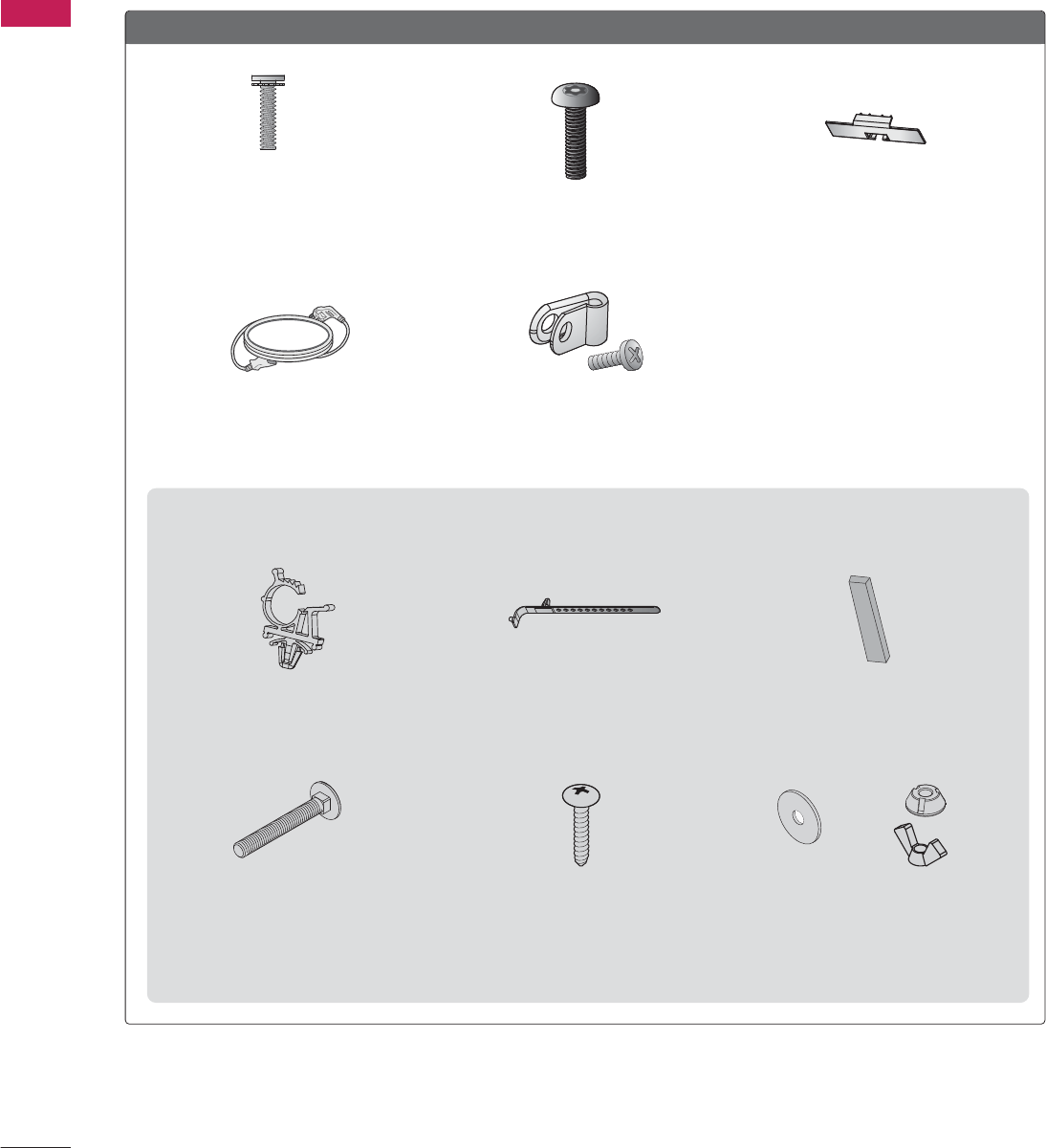
(For 32/37/42LD650H, 32/37/42LD655H, 32/37/42LD660H, 32/37/42LD665H)
Screw for
stand fixing
(Refer to P.27)
Screws for
stand assembly
(Refer to P.20)
x 8
(M4 x 20)
F
For 32/37/42/47/55LD650H, 32/37/42LD655H, 32/37/42LD660H, 32/37/42LD665H
Nuts for
stand fixing
(Refer to P.27)
x 2 x 2
Rubbers for
stand fixing
(Refer to P.27)
x 4
x 2
Protection Cover
(Refer to P.20)
x 2
Torx plus
Star-head screw
(Refer to P.20)
Protective bracket and
screw for power cord
(Refer to P.24)
PREPARATION
11
Screws for
stand fixing
(Refer to P.27)
Washers for
stand fixing
(Refer to P.27)
x 2
Screw for stand fixing
(Refer to P.27)
F
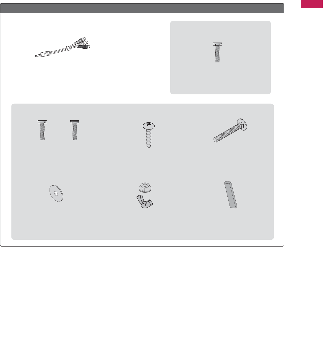
For 32/37/42/47/55LV555H
Nuts for
stand fixing
(Refer to P.27)
x 2 x 2
Rubbers for
stand fixing
(Refer to P.27)
x 4
x 2
(For 32/37/42LV555H)
Composite gender cable
Screws for stand assembly
(Refer to P.21)
x 4
(M4 x 14)
x 4
(M4 x 20)
Screws for stand assembly
(Refer to P.22)
x 8
(M4 x 12)
(For 47/55LV555H)
PREPARATION
12
PREPARATION
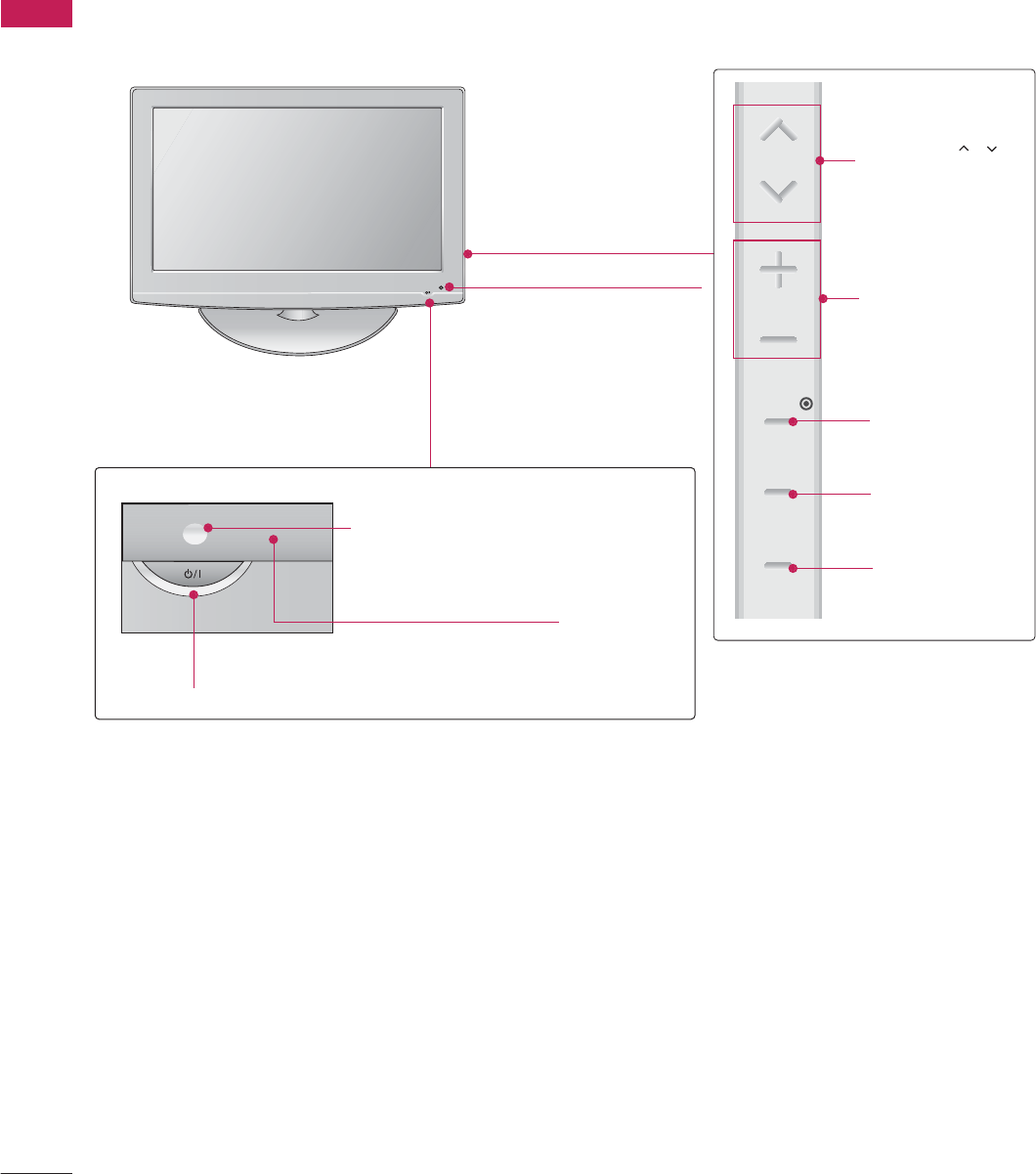
FRONT PANEL INFORMATION
■
Image shown may differ from your TV.
POWER Button
Power/Standby Indicator
Illuminates red in standby mode.
Illuminates blue when the set is
switched on.
CH
VOL
MENU
INPUT
ENTER
VOLUME (+, -)
Buttons
ENTER Button
MENU Button
INPUT Button
Remote Control Sensor
CHANNEL( , )
Buttons
Intelligent Sensor
Adjusts picture according to
the surrounding conditions.
32/37/42LG710H
PREPARATION
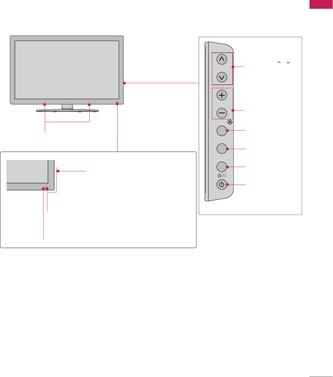
13
Intelligent Sensor
Adjusts picture according to the surrounding condi-
tions.
Power/Standby Indicator
Illuminates red in standby mode.
Illuminates blue when the set is
switched on.
Remote Control Sensor
SPEAKER
CH
VOL
ENTER
INPUT
MENU
VOLUME (+, -)
Buttons
ENTER Button
MENU Button
INPUT Button
POWER Button
CHANNEL( , )
Buttons
32/37/42/47/55LD650H, 32/37/42LD655H, 32/37/42LD660H, 32/37/42LD665H
PREPARATION
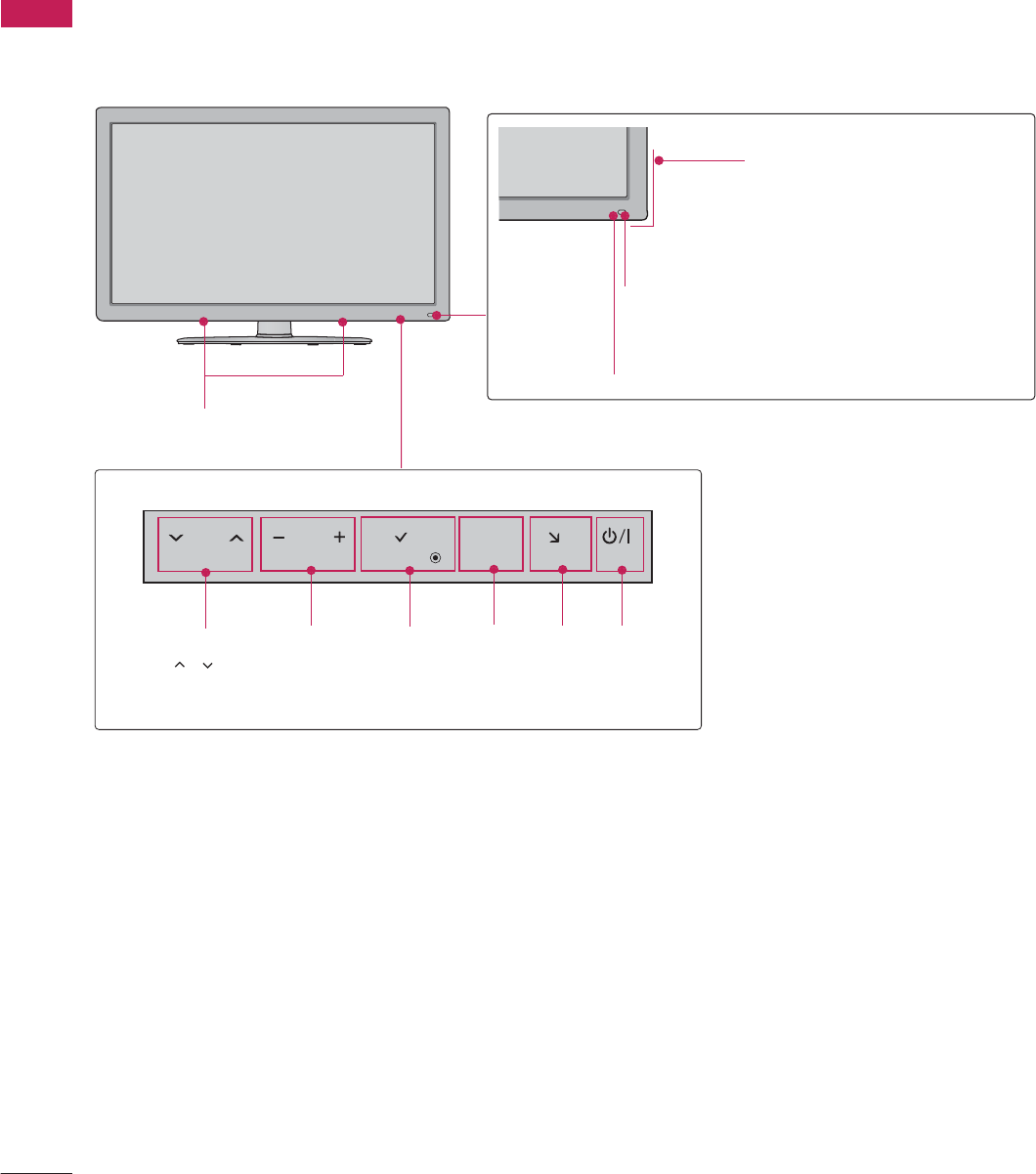
14
PREPARATION
Intelligent Sensor
Adjusts picture according to the surrounding
conditions.
Power/Standby Indicator
Illuminates red in standby mode.
Illuminates blue when the set is
switched on.
Remote Control Sensor
SPEAKER
32/37/42/47/55LV555H
ENTER
CH VOL HOME
H
INPUT
CHANNEL
( , )
Buttons
VOLUME
(+, -)
Buttons
ENTER
Button
MENU
Button
INPUT
Button
POWER
Button
PREPARATION
15
SERVICE
ONLY
OPTICAL
DIGITAL
UPDATE
RESET
LAN2
1
HDMI/DVI IN
2
1
RJP
INTERFACE
SPEAKER
OUT
8
RGB IN (PC) AUDIO IN
(RGB/DVI)
TV-LINK CFG
GAME
CONTROL/MPI
RS-232C IN
(SERVICE ONLY)
AUDIO OUT
AV IN 1
AUDIO
VIDEO
MONO
/
COMPONENT
IN
LR
LAN
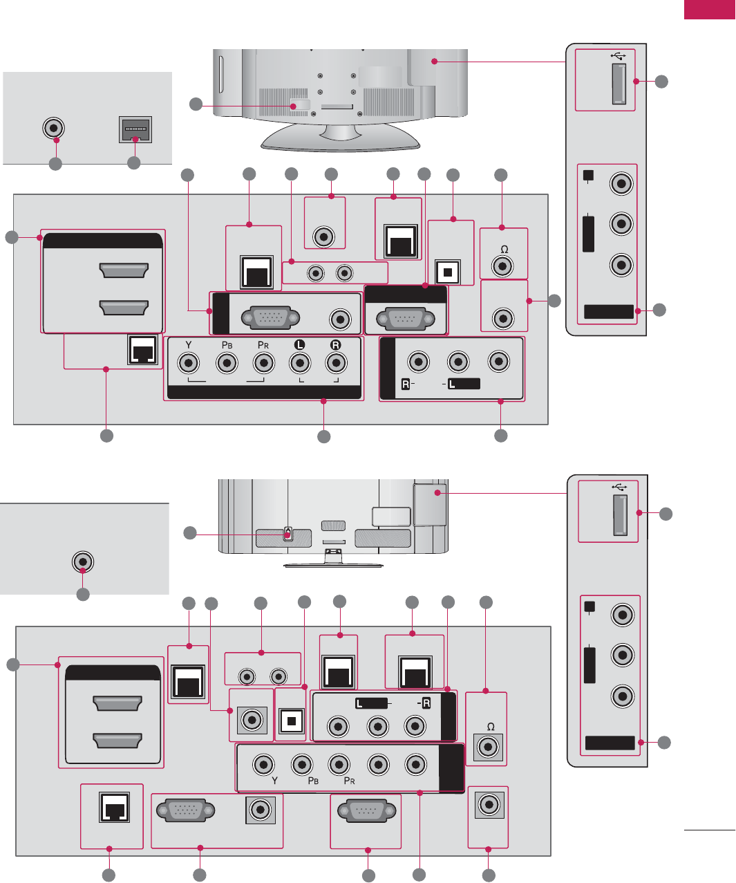
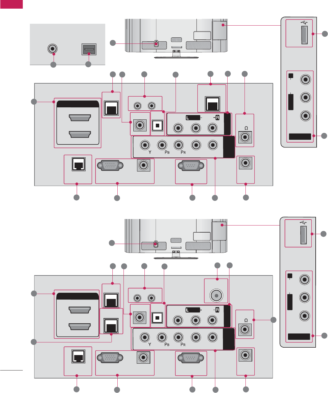
■
Image shown may differ from your TV.
BACK PANEL INFORMATION
AV IN 2
L/MONO
R
AUDIO
VIDEO
USB IN
REMOTE
CONTROL OUT
OPTICAL
DIGITAL
AUDIO OUT
AV IN 1
AUDIO
VIDEO
MONO
/
UPDATE
RESET
LAN
(SERVICE ONLY)
COMPONENT IN
VIDEO
AUDIO
HDMI/DVI IN
2
1(DVI)
RJP
INTERFACE
SPEAKER OUT
8
RGB(PC)
AUDIO
(RGB/DVI)
RGB IN
RS-232C IN
(SERVICE ONLY)
TV-LINK
CFG
GAME
CONTROL
10
38
ANTENNA IN
ANTENNA IN
M.P.I.
M.P.I.
7
1
492
13
14
15
6
6
5
32/37/42LG710H
12 11
11
16
32/37/42LD660H, 32/37/42LD665H
AC IN
1
13
17 4
218
9
6
58
AV IN 2
L/MONO
R
AUDIO
VIDEO
USB IN
15
7
11
12
11
16
17
ANTENNA IN
14
PREPARATION
16
PREPARATION
ANTENNA IN M.P.I.
14 6
32/37/42LD650H, 32/37/42LD655H
REMOTE
CONTROL
OUT
OPTICAL
DIGITAL
UPDATE
RESET
LAN
HDMI/DVI IN
2
1
RJP
INTERFACE
SPEAKER
OUT
8
RGB IN (PC) AUDIO IN
(RGB/DVI)
TV-LINK CFG
GAME
CONTROL
RS-232C IN
(SERVICE ONLY)
AUDIO OUT
AV IN 1
AUDIO
VIDEO
MONO
/
COMPONENT
IN
LR
AC IN
1
13
34
210
9
6
58
AV IN 2
L/MONO
R
AUDIO
VIDEO
USB IN
15
7
47/55LD650H
REMOTE
CONTROL
OUT
OPTICAL
DIGITAL
UPDATE
RESET
LAN
HDMI/DVI IN
2
1
RJP
INTERFACE
SPEAKER
OUT
8
RGB IN (PC) AUDIO IN
(RGB/DVI)
TV-LINK CFG
GAME CONTROL
/ M.P.I.
RS-232C IN
(SERVICE ONLY)
AUDIO OUT
AV IN 1
AUDIO
VIDEO
MONO
/
COMPONENT
IN
LR
ANTENNA IN
1
13
34
210
6
58
7
9
14 11
11
AC IN
AV IN 2
L/MONO
R
AUDIO
VIDEO
USB IN
15
12
12
11
16
16
11
PREPARATION
17
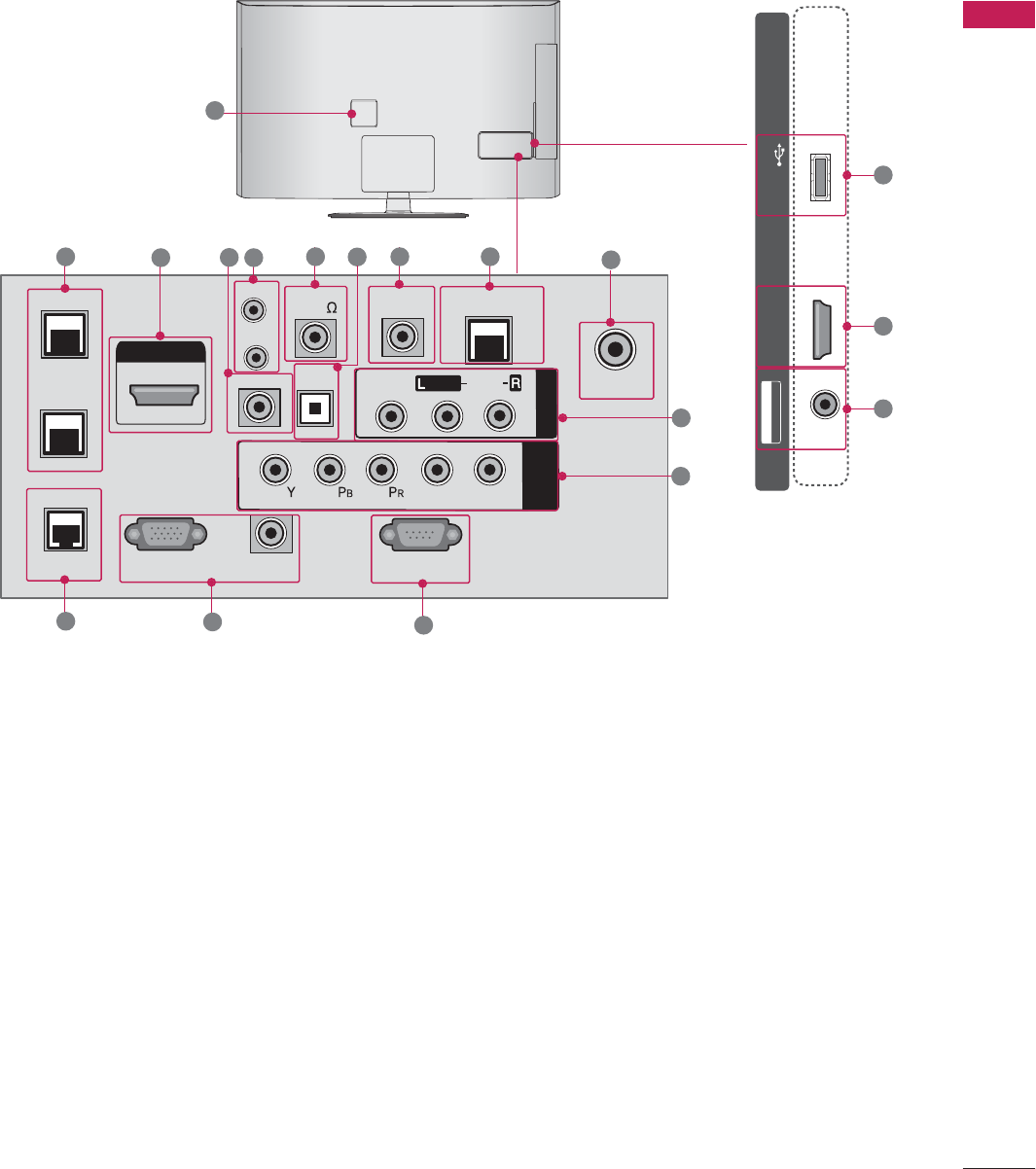
32/37/42/47/55LV555H
SERVICE
ONLY
OPTICAL
DIGITAL
UPDATE
RESET
LAN 2
HDMI/DVI IN
1
INTERFACE
SPEAKER
OUT
(8 )
RGB IN (PC) AUDIO IN
(RGB/DVI)
TV-LINK CFG
GAME CONTROL
/ MPI
RS-232C IN
(SERVICE ONLY)
AUDIO OUT
A1 NI V
AUDIO
VIDEO
MONO
/
T
N
E
NOPM
O
C
NI
LR
LAN 1
RJP
ANTENNA IN
17 1 4 918 6
13 7
14
11
12
58
15
2
USB IN
AV IN 2
VIDEO / AUDIO
USB IN
HDMI/DVI
IN 2
16
1
11

PREPARATION
18
PREPARATION
HDMI/DVI IN
Digital Connection. Supports HD video and Digital
audio.
Accepts DVI video using an adapter or HDMI to DVI
cable (not included)
RGB IN (PC)
Analog PC Connection. Uses a D-sub 15 pin cable
(VGA cable).
AUDIO IN (RGB/DVI)
1/8” headphone jack for analog PC audio input.
LAN (SERVICE ONLY)
For connecting to a control network.
RESET
Performs a hardware reset.
UPDATE
Enables/disables software downloads and debug mode.
TV - LINK CFG
Computer input for programming Free To Guest ser-
vices.
GAME CONTROL
Input port for third party game Controllers.
M.P. I.
Allows VOD/PPV devices or set-top boxes to control
the TV.
RS-232C IN (SERVICE ONLY)
Used for software updates.
OPTICAL DIGITAL AUDIO OUT
Optical digital audio output for use with amps and
home theater systems.
Note: In standby mode, this port doesn’t work.
SPEAKER OUT 8Ω
For use with external speakers.
REMOTE CONTROL OUT
IR output for controlling an auxiliary device.
AV (Audio/Video) IN 1/2
Analog composite connection. Supports standard
definition video only (480i).
COMPONENT IN
Analog Connection. Supports HD.
Uses a red, green, and blue cable for video & a red
and white cable for audio.
RJP INTERFACE (REMOTE JACK PACK PORT)
Connect this to an LG remote jack pack system.
ANTENNA IN
Connect an antenna to receive over-the-air (OTA)
signals.
Power Cord Socket
AC power input.
Caution: Never attempt to operate the TV on DC
power.
USB IN
Used for viewing multimedia files.
LAN
For connecting to a control network.
SERVICE ONLY
Used for software updates.
1
2
3
4
5
6
8
7
9
11
12
13
14
15
10
16
17
18
PREPARATION
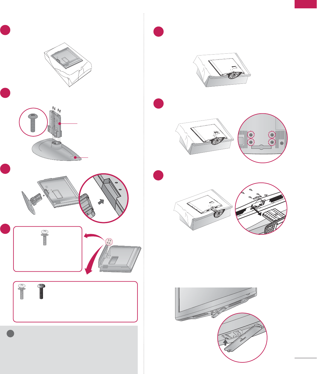
19
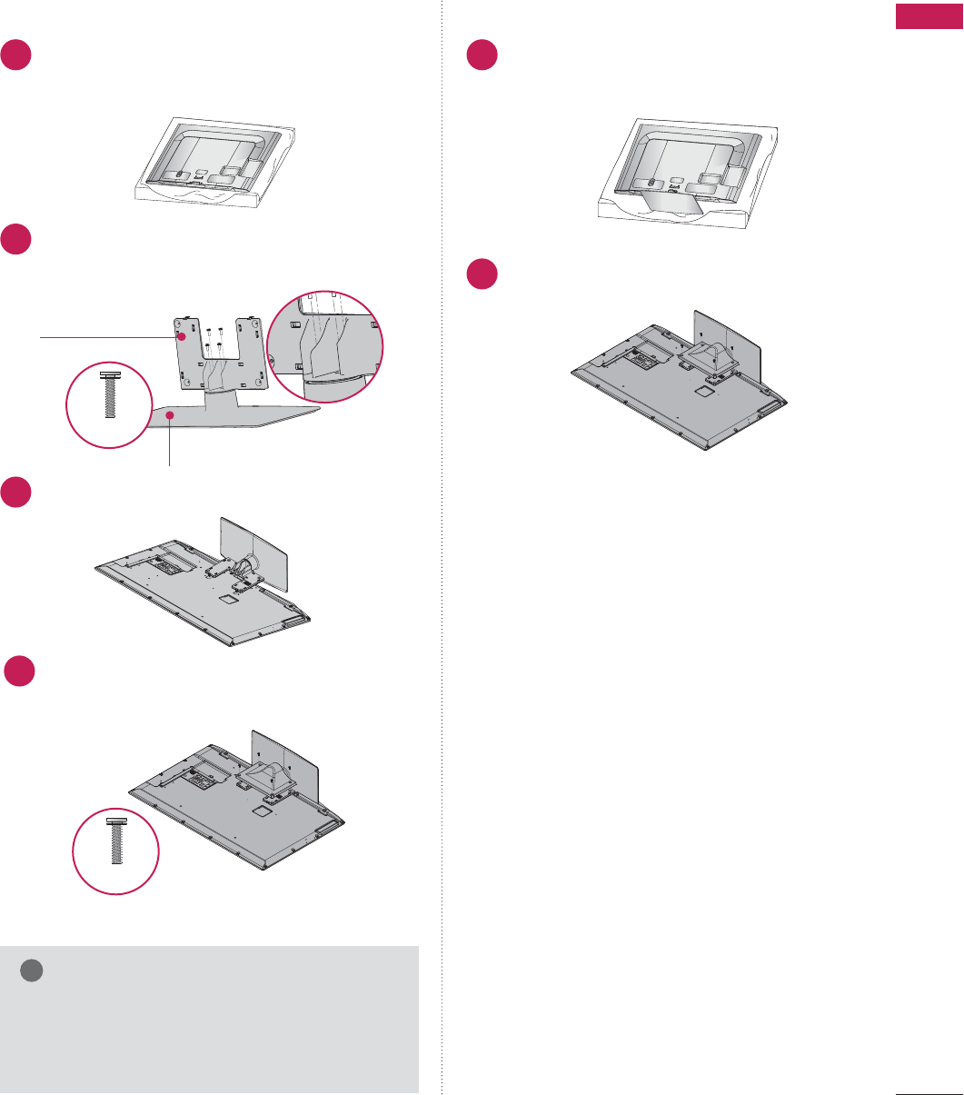
STAND INSTRUCTIONS
Carefully place the TV screen side down on a
cushioned surface to protect the screen from
damage.
Assemble the parts of the S
STAND BODY
with the
STAND BASE
of the TV.
1
2
Insert the stand as shown.
3
STAND BODY
STAND BASE
■
Image shown may differ from your TV.
G
When assembling the desk type stand, make sure
the screws are fully tightened (If not tightened
fully, the TV can tilt forward after the protuct
installation). Do not over tighten.
NOTE
!
DETACHMENT
Carefully place the TV screen side down on a
cushioned surface to protect the screen from
damage.
1
Remove the four screws that hold the base on.
2
Detach the stand from the TV.
3
INSTALLATION
4
or
x 4
Tighten the stand with the
four screws (provided as parts
of the TV).
Tighten the two of these four screws
and the two Torx plus star head screws
(provided as parts of the TV) to secure the TV. Tighten
the two Torx plus star head screws with a star head dri-
ver bit (not provided as parts of the TV).
x 2 x 2
After removing the stand, install the included
p
protection cover
over the hole for the stand.
Press the
PROTECTION COVER
into the TV
until you hear it click.
PROTECTION COVER
32/37/42LG710H
PREPARATION
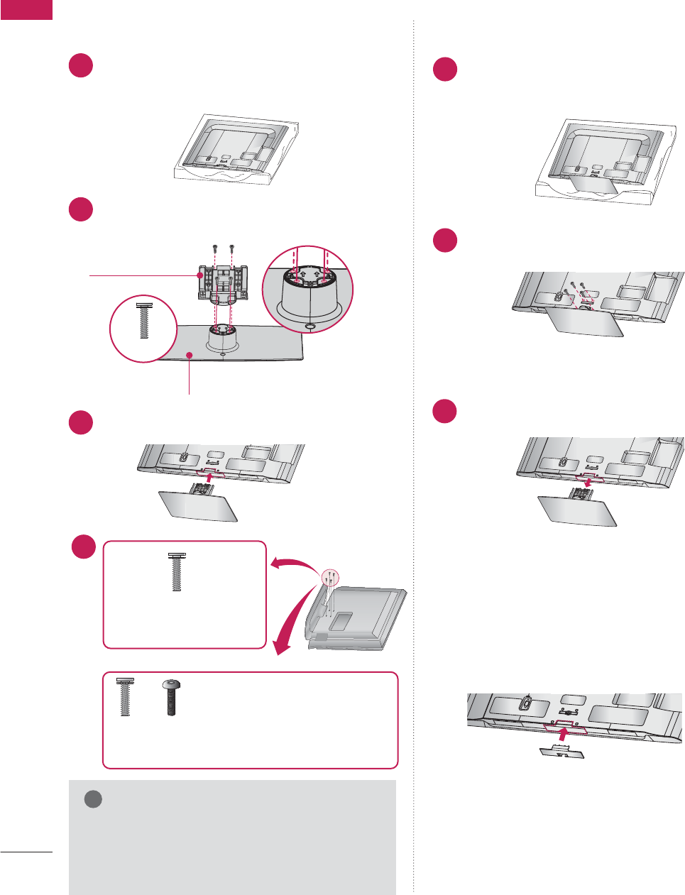
20
PREPARATION
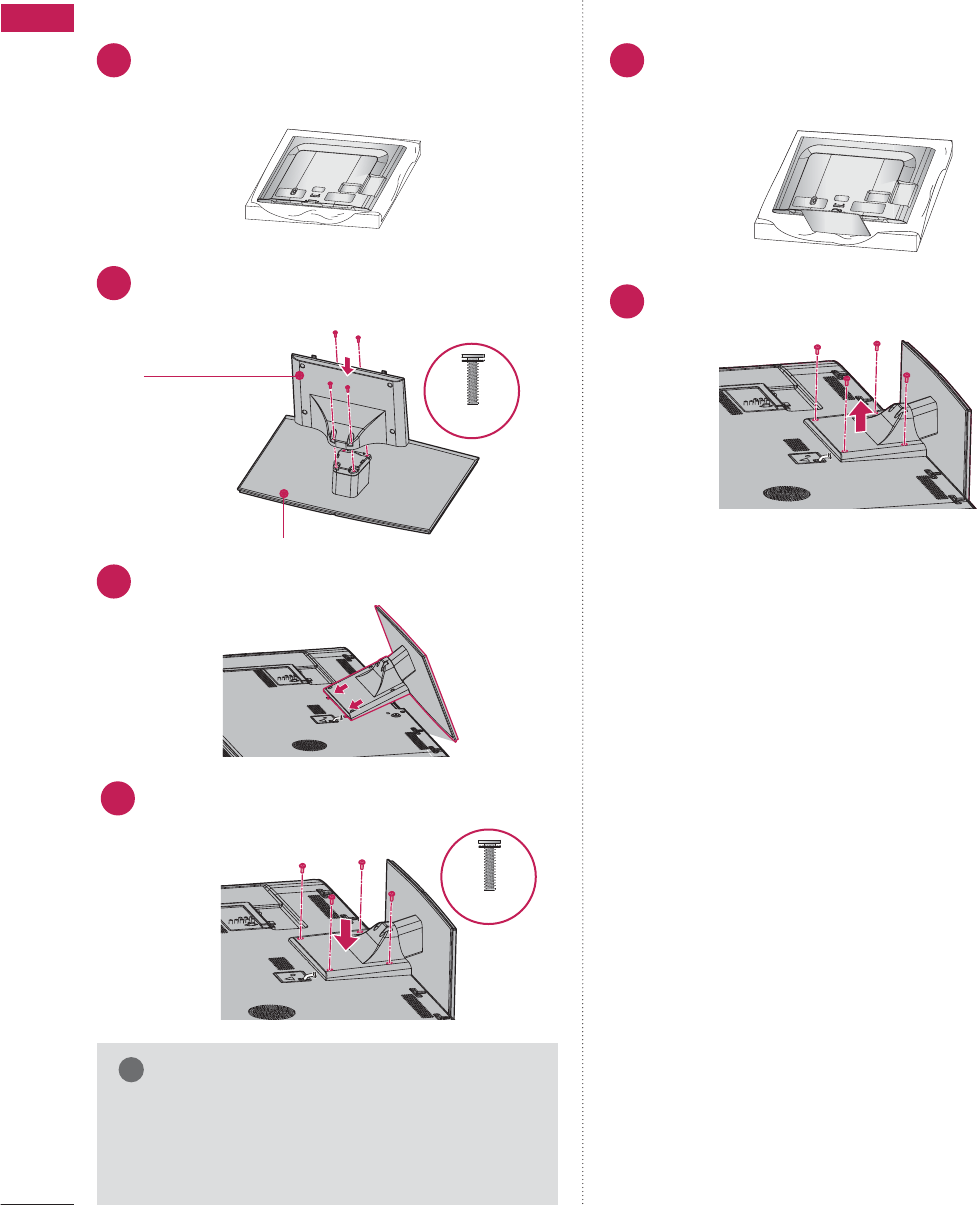
32/37/42/47/55LD650H, 32/37/42LD655H, 32/37/42LD660H, 32/37/42LD665H
ACIN
CABLEMANAGEMENT
Carefully place the TV screen side down on a
cushioned surface to protect the screen from
damage.
Assemble the parts of the S
STAND BODY
with the
STAND BASE
of the TV.
1
2
Assemble the TV as shown.
3
AC IN
CABLE M
ANAGEMENT
STAND BODY
STAND BASE
G
When assembling the desk type stand, make sure
the screws are fully tightened (If not tightened
fully, the TV can tilt forward after the protuct
installation). Do not over tighten.
NOTE
!
DETACHMENT
ACIN
CABLEMANAGEMENT
Carefully place the TV screen side down on a
cushioned surface to protect the screen from
damage.
1
Remove the screws that hold the stand on.
2
Detach the stand from TV.
3
AC IN
CABLE M
ANAGEMENT
INSTALLATION
After removing the stand, install the included
p
protection cover
over the hole for the stand.
Press the
PROTECTION COVER
into the TV
until you hear it click.
PROTECTION COVER
AC IN
CABLEMANAGEMENT
M4 x 20
4
or
x 4
Tighten the stand with the
four screws (provided as parts
of the TV).
Tighten the two of these four screws
and the two Torx plus star head screws
(provided as parts of the TV) to secure the TV. Tighten
the two Torx plus star head screws with a star head dri-
ver bit (not provided as parts of the TV).
x 2 x 2
PREPARATION
21
32/37/42LV555H
ACIN
CABLEMANAGEMENT
Carefully place the TV screen side down on a
cushioned surface to protect the screen from
damage.
Assemble the parts of the S
STAND BODY
with the
STAND BASE
of the TV.
1
2
Assemble the TV as shown.
3
G
When assembling the desk type stand, make sure
the screws are fully tightened (If not tightened
fully, the TV can tilt forward after the protuct
installation). Do not over tighten.
NOTE
!
DETACHMENT
ACIN
CABLEMANAGEMENT
Carefully place the TV screen side down on a
cushioned surface to protect the screen from
damage.
1
Remove the screws that hold the stand on.
2
INSTALLATION
4Install the 4 screws into the holes shown.
STAND BODY
STAND BASE
M4 x 20
M4 x 14
PREPARATION
22
PREPARATION
47/55LV555H
ACIN
CABLEMANAGEMENT
Carefully place the TV screen side down on a
cushioned surface to protect the screen from
damage.
Assemble the parts of the S
STAND BODY
with the
STAND BASE
of the TV.
1
2
Assemble the TV as shown.
3
G
When assembling the desk type stand, make sure
the screws are fully tightened (If not tightened
fully, the TV can tilt forward after the protuct
installation). Do not over tighten.
NOTE
!
DETACHMENT
ACIN
CABLEMANAGEMENT
Carefully place the TV screen side down on a
cushioned surface to protect the screen from
damage.
1
Remove the screws that hold the stand on.
2
INSTALLATION
4
STAND BODY
STAND BASE
M4 x 12
Install the 4 screws into the holes shown.
M4 x 12
PREPARATION
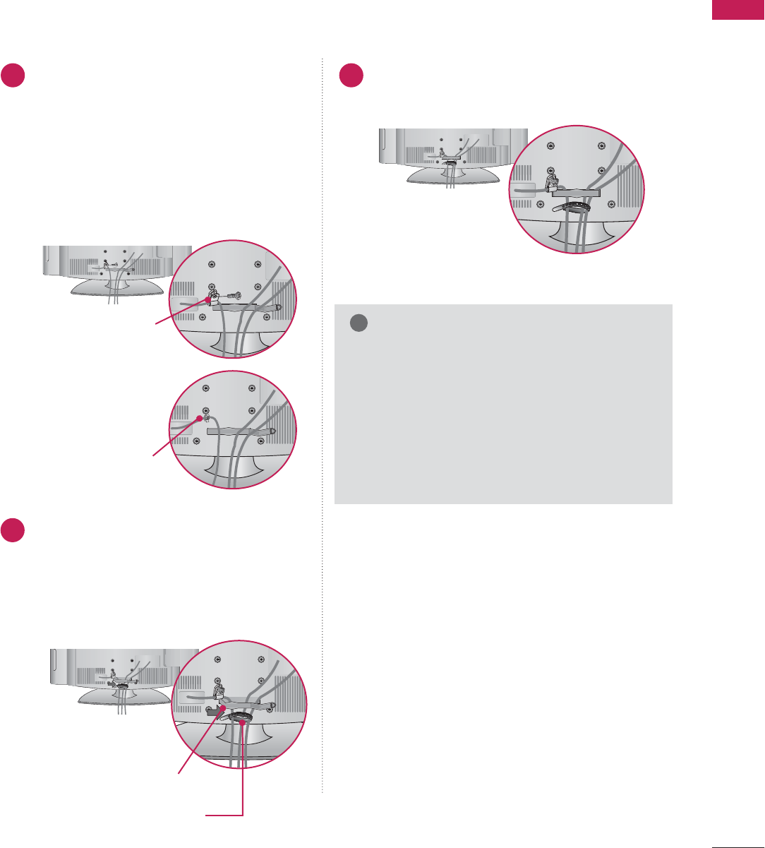
23
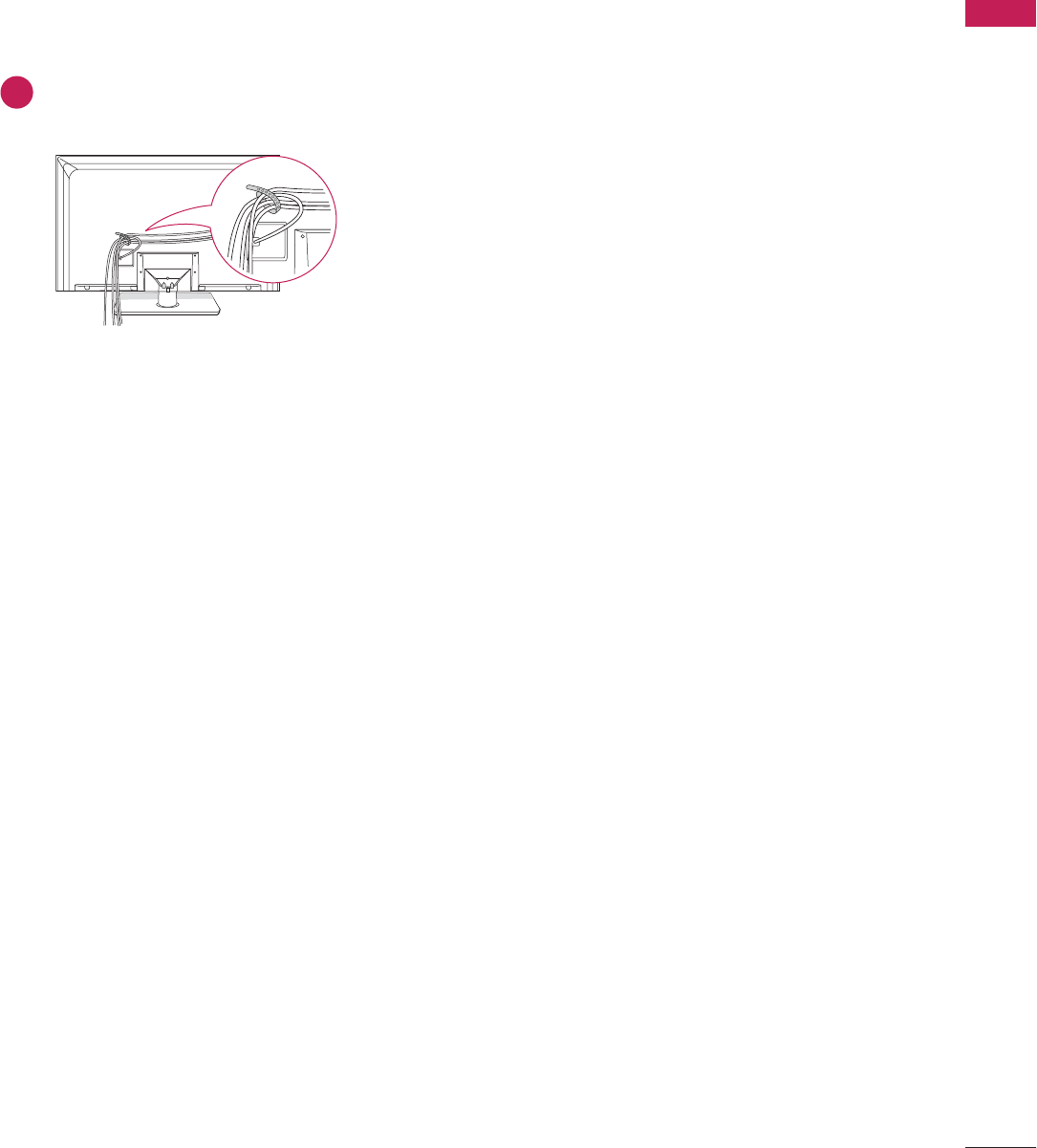
CABLE MANAGEMENT
■
Image shown may differ from your TV.
Connect the cables as necessary.
To connect additional equipment, see the
EXTERNAL EQUIPMENT SETUP section.
To help prevent the power cable from being
removed by accident, secure the power
cable with the included P
P
ROTECTIVE
BRACKET /SCREW. The 32LG710H use a
Plug-in type Holder instead of using a
screw.
Open the CABLE MANAGEMENT CLIP as
shown.
If a CABLE HOLDER was included with your
TV, install it as shown.
1
2
Put the cables inside the CABLE MANAGEMENT
CLIP and snap it closed.
3
G
Do not hold the CABLE MANAGEMENT CLIP
when moving the TV.
- If the TV is dropped, you may be injured or the
product may be broken.
G
With some TVs, the PLUG-IN TYPE HOLDER
and the CABLE HOLDER are included. If these
holders are inserted into the hole provided on
back of the TV, they cannot be removed.
NOTE
!
CABLE MANAGEMENT CLIP
CABLE HOLDER
PROTECTIVE BRACKET/SCREW
PLUG-IN TYPE HOLDER
(For 32LG710H model)
Or
32/37/42LG710H
PREPARATION
24
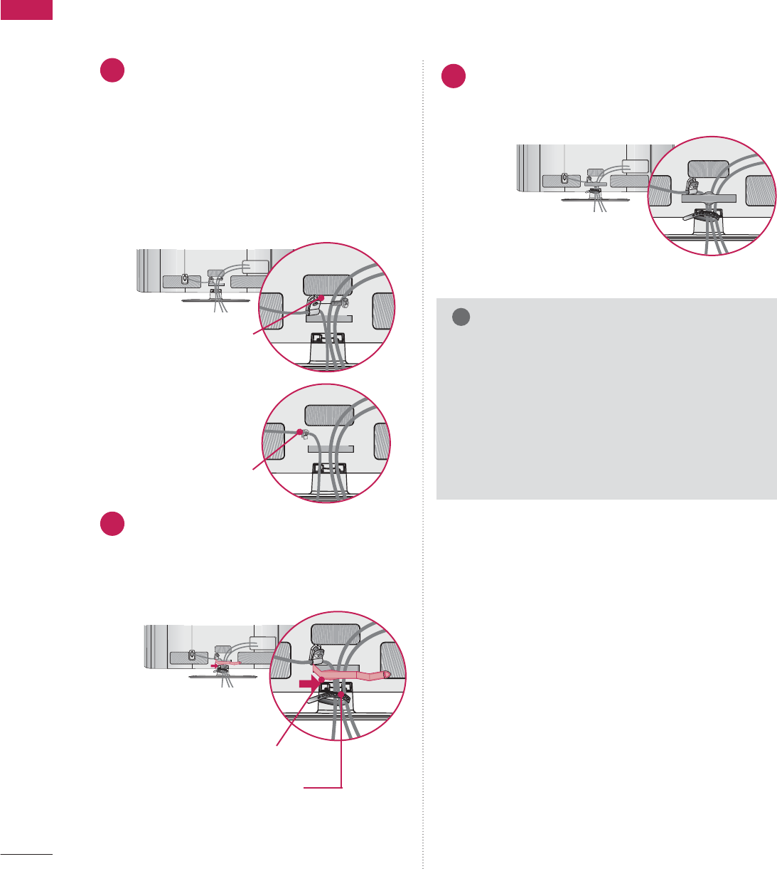
PREPARATION
32/37/42/47/55LD650H, 32/37/42LD655H, 32/37/42LD660H, 32/37/42LD665H
Connect the cables as necessary.
To connect additional equipment, see the
EXTERNAL EQUIPMENT SETUP section.
To help prevent the power cable from being
removed by accident, secure the power cable
with the included
P
ROTECTIVE BRACKET
/SCREW. The 32/37/42LD650H,
32/37/42LD655H, 32/37/42LD660H,
32/37/42LD665H use a Plug-in type
Holder instead of using a screw.
1
AC IN
Open the CABLE MANAGEMENT CLIP as
shown.
If a CABLE HOLDER was included with your
TV, install it as shown.
2
AC IN
AC IN
PROTECTIVE BRACKET/SCREW
PLUG-IN TYPE HOLDER
(For 32/37/42LD650H,
32/37/42LD655H,
32/37/42LD660H,
32/37/42LD665H
model)
Or
G
Do not hold the CABLE MANAGEMENT CLIP
when moving the TV.
- If the TV is dropped, you may be injured or the
product may be broken.
G
With some TVs, the PLUG-IN TYPE HOLDER
and the CABLE HOLDER are included. If these
holders are inserted into the hole provided on
back of the TV, they cannot be removed.
NOTE
!
CABLE MANAGEMENT CLIP
CABLE HOLDER
(For 32/37/42LD650H,
32/37/42LD655H,
32/37/42LD660H,
32/37/42LD665H
model)
Put the cables inside the CABLE MANAGEMENT
CLIP and snap it closed.
3
PREPARATION
25
32/37/42/47/55LV555H
Gether and bind the cables with the cable
holder on the TV back cover.
1
PREPARATION
26
PREPARATION
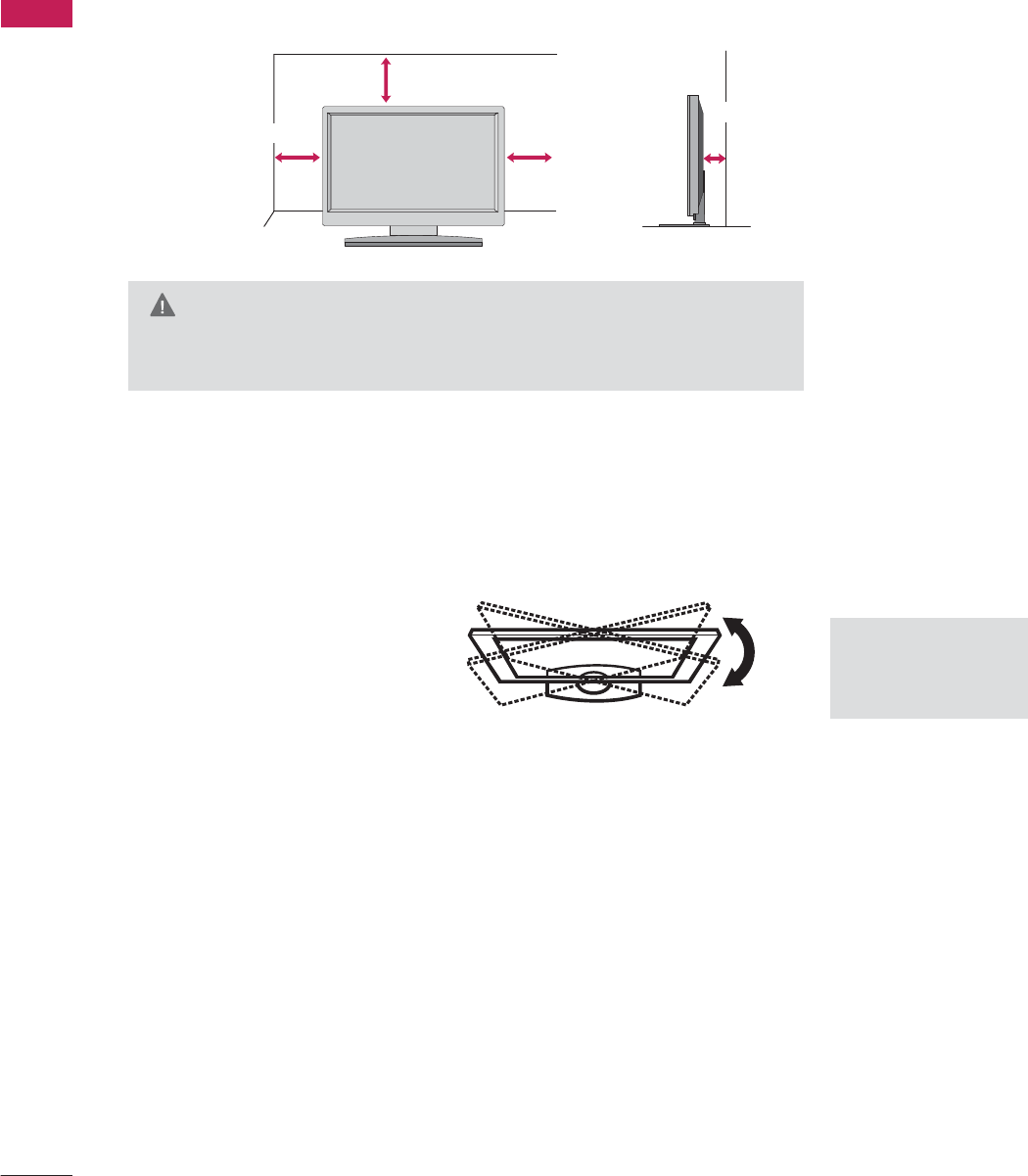
DESKTOP PEDESTAL INSTALLATION
For proper ventilation, allow a clearance of 4 inches on all four sides from the wall.
■
Image shown may differ from your TV.
4 inches
4 inches
4 inches
4 inches
SWIVEL STAND
After installing the TV, you can adjust the TV set manually to the left or right direction to suit your viewing posi-
tion.
20°: 47/55LD650H,
47/55LV555H
90°: Other Models
G
G
Ensure adequate ventilation by following the clearance recommendations.
G
Do not mount near or above any type of heat source.
CAUTION
PREPARATION
27
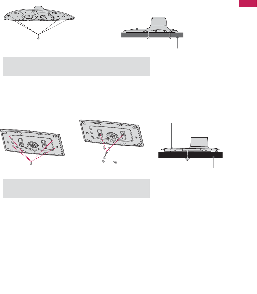
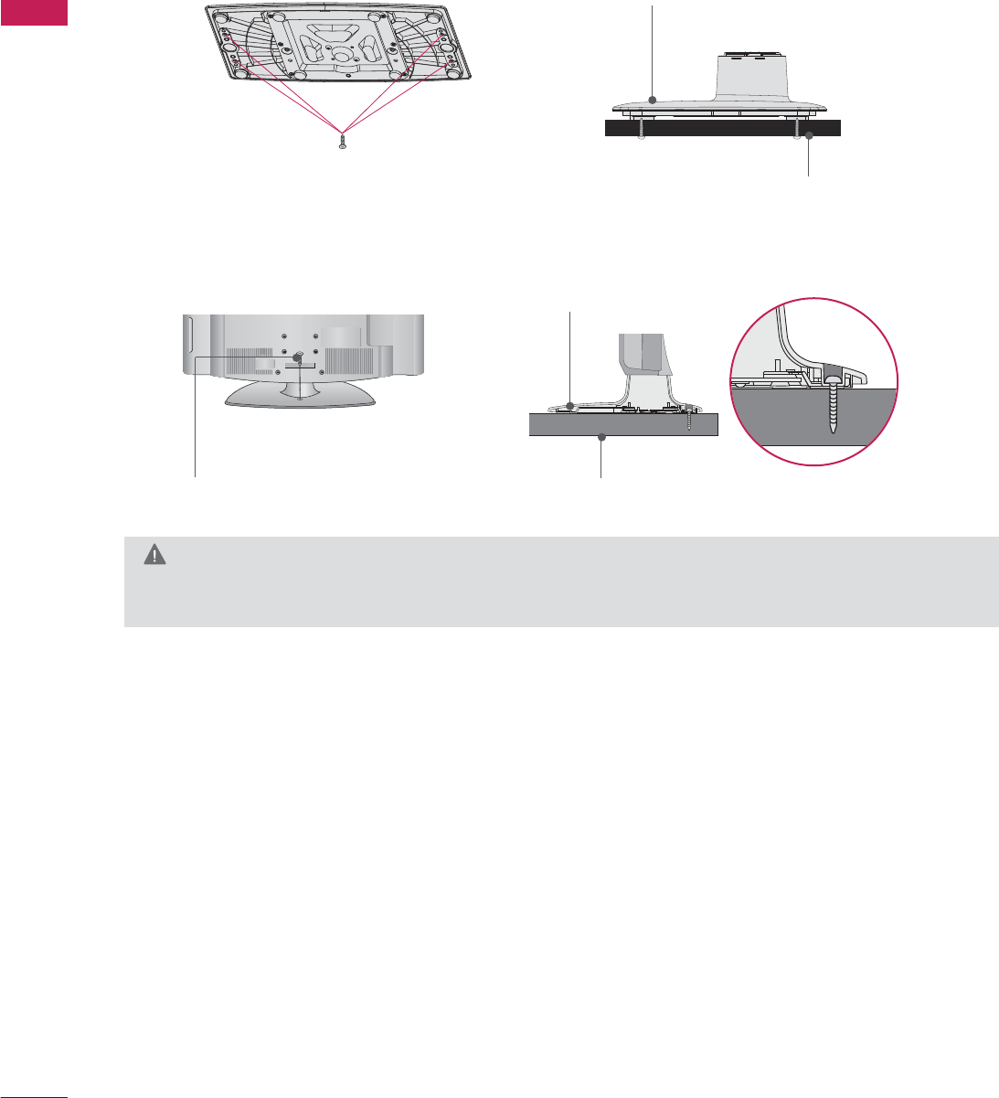
ATTACHING THE TV TO A DESK
The TV should be attached to a desk so it cannot be pulled in a forward/backward direction, potentially causing
injury or damaging the product.
4-Screws
(not provided as parts of the product)
G
Recommended screw size: M5 x L (
*L: Table depth + 8
~
10mm
)
ex) Table depth: 15mm, Screw: M5 x 25
Desk
Stand
32/37/42LD650H, 32/37/42LD655H, 32/37/42LD660H, 32/37/42LD665H, 32/37/42LV555H
Stand
Desk
32/37/42LG710H
2-Screws, 2-Washers, 2-Nuts, 4-Rubbers
(provided as parts of the product)
G
G
You can select any type of attachment (Type 1 or Type 2)
G
Do not over tighten.
Type 1 Type 2
4-Screws
(not provided as parts of the product)
or
PREPARATION
28
PREPARATION
G
G
To prevent TV from falling over, the TV should be securely attached to the floor/wall per installation
instructions. Tipping, shaking, or rocking the TV may cause injury.
WARNING
1-Screw
(provided as parts of the product) Desk
Stand
47/55LD650H, 47/55LV555H
Stand
Desk
4-Screws
(not provided as parts of the product)
EXCEPT 47/55LD650H, 47/55LV555H
PREPARATION
29
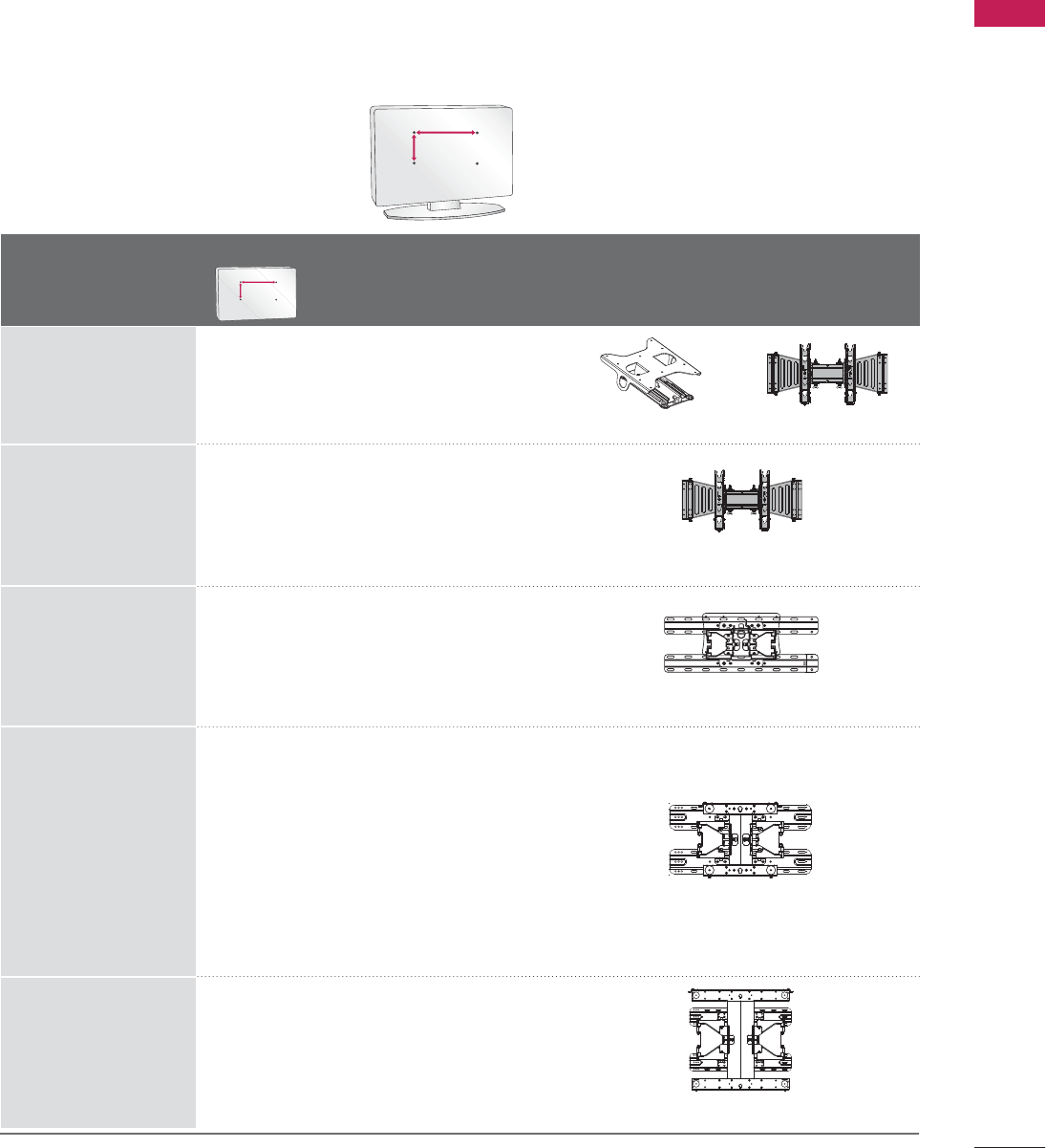
VESA WALL MOUNTING
Install your wall mount on a solid wall perpendicular to the floor. When attaching to other building materials, please
contact an installer. If installed on a ceiling or slanted wall, it may fall and result in severe personal injury.
We recommend that you use an LG brand wall mount when mounting the TV to a wall.
LG recommends that wall mounting be performed by a qualified professional installer.
AA
BB
Model
VESA (A *B)
Standard Screw Quantity Wall Mounting Bracket
(sold separately)
32LG710H
37LG710H,
42LG710H
32LD650H,
32LD655H,
32LD660H,
32LD665H,
32LV555H
37LD650H,
37LD655H,
37LD660H,
37LD665H,
37LV555H,
42LD650H,
42LD655H,
42LD660H,
42LD665H,
47LD650H
42LV555H,
47LV555H
55LD650H,
55LV555H
200 * 10 0 M 4 4
200 * 10 0 M 4 4
200 * 200 M6 4
400 * 400 M6 4
200 * 200 M6 4
AA
BB
AW-47LG30M
LSW100B, LSW100BG
LSW200B, LSW200BG
LSW400B, LSW400BG
RW230 AW-47LG30M
PREPARATION
30
PREPARATION
G
Do not install your wall mount kit while your TV is turned on. It may result in personal injury due to electric shock.
CAUTION
G
Screw length needed depends on the wall mount
used. For further information, refer to the instruc-
tions included with the mount.
G
Standard dimensions for wall mount kits are shown
in the table.
G
When purchasing our wall mount kit, a detailed
installation manual and all parts necessary for
assembly are provided.
G
Do not use screws longer then the standard dimen-
sion, as they may cause damage to the inside of
the TV.
G
For wall mounts that do not comply with the VESA
standard screw specifications, the length of the
screws may differ depending on their specifica-
tions.
G
Do not use screws that do not comply with the
VESA standard screw specifications.
Do not use fasten the screws too strongly, this may
damage the TV or cause the TV to a fall, leading to
personal injury. LG is not liable for these kinds of
accidents.
G
LG is not liable for TV damage or personal injury
when a non-VESA or non specified wall mount is
used or the consumer fails to follow the TV installa-
tion instructions.
NOTE
!
PREPARATION
31
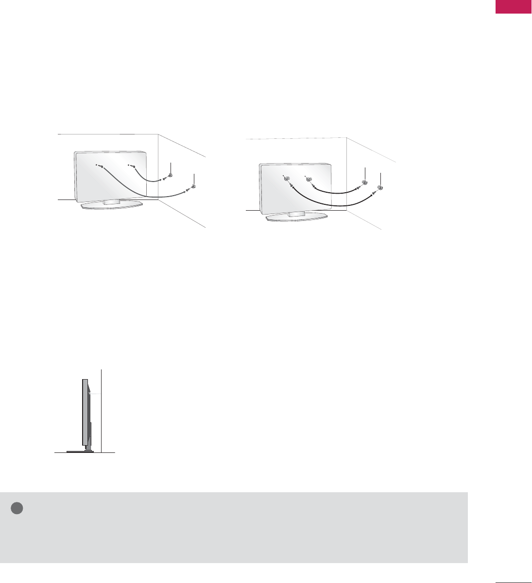
SECURING THE TV TO THE WALL TO PREVENT FALLING
WHEN THE TV IS USED ON A STAND
We recommend that you set up the TV close to a wall so it cannot fall over if pushed backwards.
Additionally, we recommend that the TV be attached to a wall so it cannot be pulled in a forward direction,
potentially causing injury or damaging the product.
Caution: Please make sure that children don’t climb on or hang from the TV.
■Insert the eye-bolts (or TV brackets and bolts) to tighten the product to the wall as shown in the pic-
ture.
*If your product has the bolts in the eye-bolts position before inserting the eye-bolts, loosen the
bolts.
* Insert the eye-bolts or TV brackets/bolts and tighten them securely in the upper holes.
Secure the wall brackets with the bolts (sold separately) to the wall. Match the height of the bracket
that is mounted on the wall to the holes in the product.
Ensure the eye-bolts or brackets are tightened securely.
■Use a sturdy rope (sold separately) to tie the product. It is safer to
tie the rope so it becomes horizontal between the wall and the prod-
uct.
■
You should purchase necessary components to prevent the TV from tipping over (when not using a wall mount).
■
Image shown may differ from your TV.
G
G
Use a platform or cabinet strong enough and large enough to support the size and weight of the TV.
G
To use the TV safely make sure that the height of the bracket on the wall and the one on the TV are the same.
NOTE
!