LG Electronics USA DT-FG Personal Computer User Manual 46475FC7A5C1F62E717864
LG Electronics USA Personal Computer 46475FC7A5C1F62E717864
Contents
- 1. users manual A
- 2. users manual B
- 3. users manual C
- 4. users manual D
users manual C
System Recovery 55
If Windows XP is already installed on your computer, simply install Widows XP
for upgrade purpose without formatting hard disk.
If you have Windows Operating system running on your computer, follow the
instructions to install Windows XP upgrade.
ⓟ
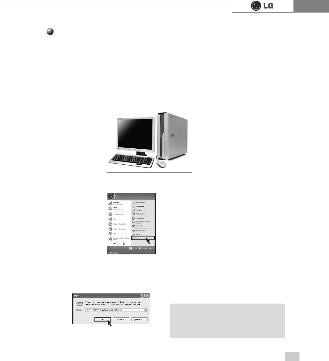
Click [Start] and then select [Run].
ⓠ
Insert Recovery CD on your computer, and then type D:ƃi386ƃwinnt32.exe/unat-
tend on the [Run] dialogue box and press [OK].
(In case CD-ROM drive is located at (D:)
ⓞTurn on the computer that has Windows XP installed.
To install Windows XP upgrade
ãIf winnt32.exe is applied without "unat
tend"option, Input Product key number,
written on the computer.You should
register Windows XP OS in 30days.
Note
5.Reinstallation of Drivers
56 Reinstallation of Drivers
After connecting a printer, you should istall the printer driver. Windows XP auto-
matically recognize the printer driver. If the printer driver does not function correct-
ly, re install the printer driver by following instructions.
5-1.Reinstalling the print driver
ⓟDouble-click
[Printer&Fax]
icon.
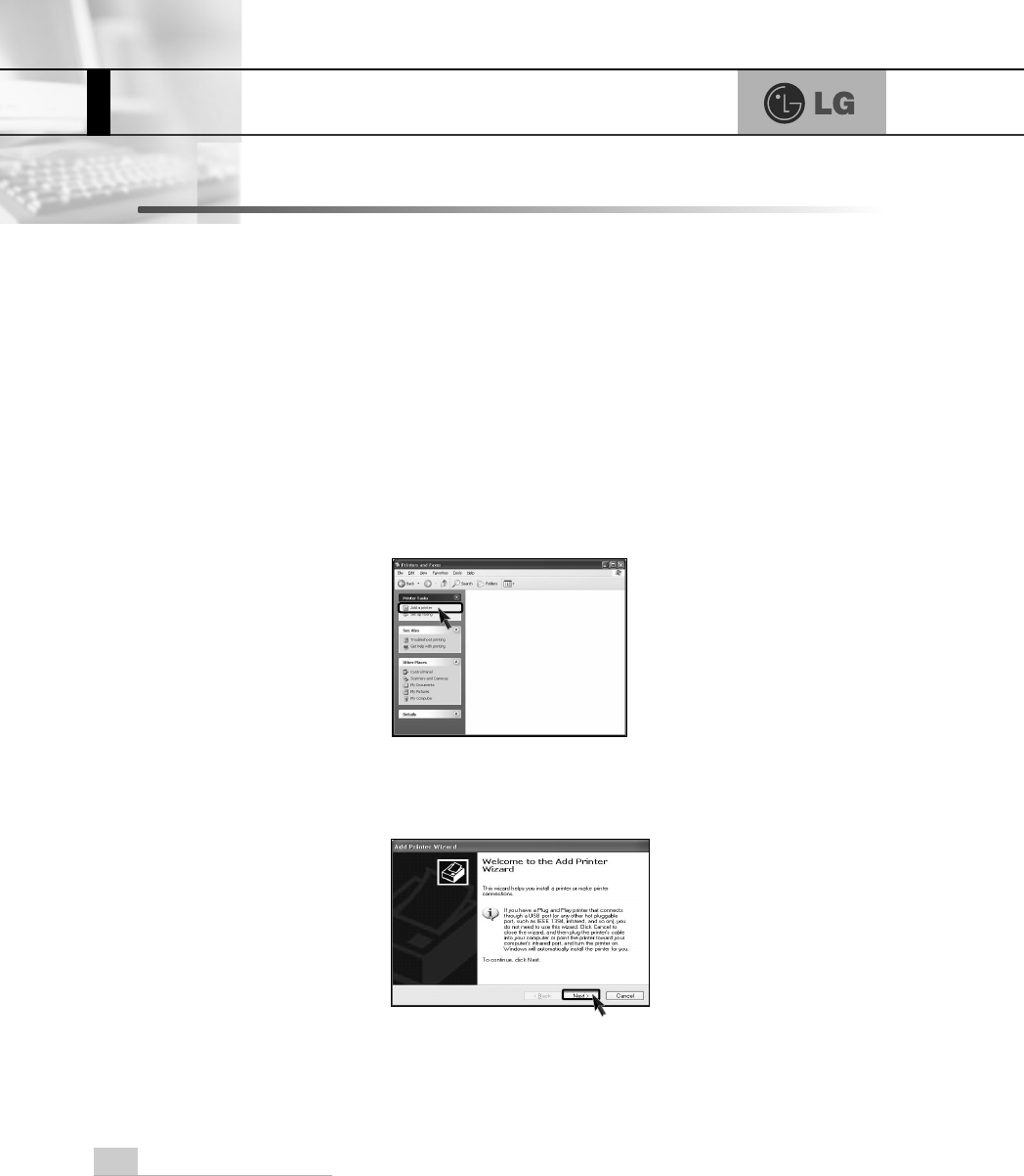
ⓠIf the following dialogue box appears, select [Add a printer].
ⓞ[Start]⍛[Control panel]⍛[Switch to classic view].
ⓡAfter "Welcome to the add printer Wizard" dialogue box appears,click
[Next]
57Reinstallation of Drivers
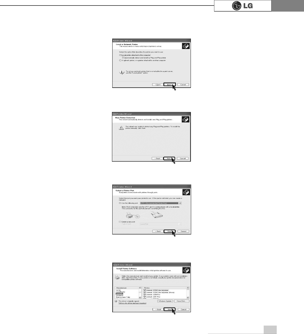
ⓢSelect [Local or Network Printer]and then click [Next].
ⓣ[New Printer Detection] dialogue box appears, click [Next].
ⓤSelect LPT1 or LPT2 and then click [Next].
ⓥSelect Manufacturer and printer, and then click [Next]. If your computer came
with an installation disk, click [Have Disk].
58 Reinstallation of Drivers
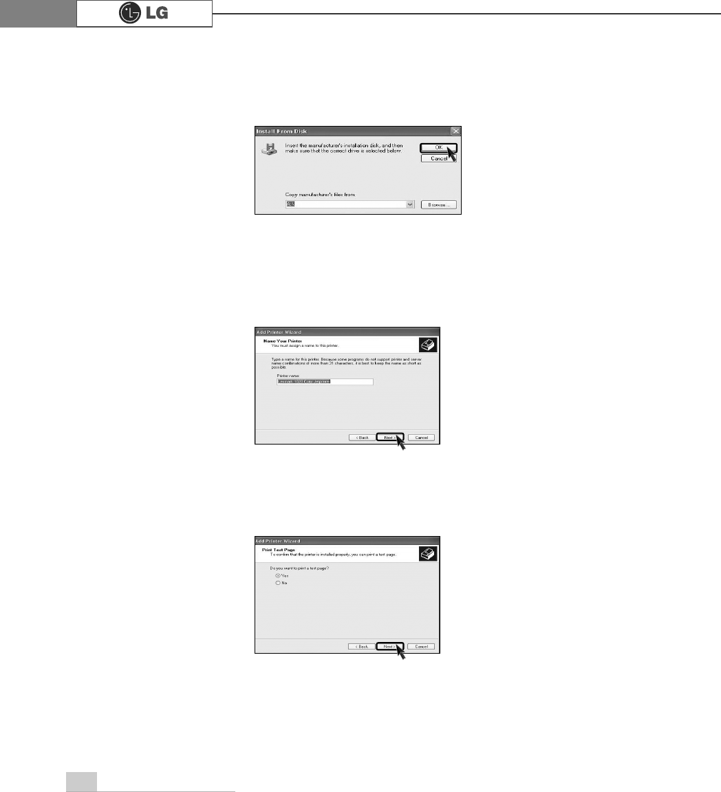
ⓧPrint Test Page appears, click [Yes] and then press [Next].
ⓦInsert the manufacturer's installation disk, and then make sure that the correct
drive is selected below.
ⓦYou must assign a Printer name, and then click [Next].
[Have disk] button was selected.
[Next] button was selected.
59Reinstallation of Drivers
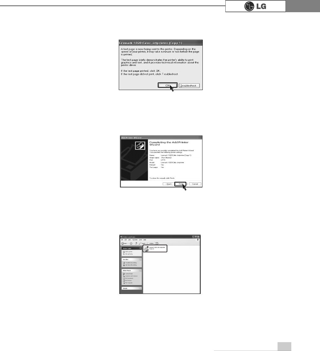
ⓨTest page is now printing, click [OK].
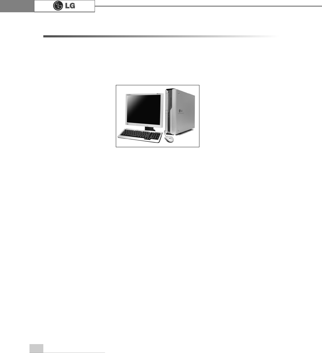
ⓩIf followig dialogue box appears, click [Finish].
⓪Adding the new printer process is now completed.
60 Reinstallation of Drivers
Sound driver enables you to listen music files and CD from your computer. Sound
driver is came with your computer. But if the computer does not recognize the
sound driver, you should re-install the sound driver.
5-2.Reinstalling the sound driver
ⓞTurn on the computer and the monitor.
ⓟInsert LG Giljabi CD into the CD-ROM drive, and then select the sound driver.
ⓠSound driver installation starts. complete the process by the instructions on the
screen.
61Reinstallation of Drivers
Video driver is came with your computer. But if the computer does not recognize
the sound driver, you should re-install the sound driver.
5-3.Reinstalling the video driver
ⓞTurn on the computer and the monitor.
ⓟInsert LG Giljabi CD into the CD-ROM drive, and then select the video driver.
ⓠVideo driver installation starts. Complete the process by the instructions on the
screen.
System Expansion
62
6-1. Opening the computer case
Always consult with your service representatives before opening the computer
case.
Follow the guidelines below when opening the case.
Opening and closing the computer case
ãQuit all running programs.
ãTurn off the computer and monitor, and unplug and remove the power cords.
ãKeep magnetic objects such as screw driver away from the parts inside the com-
puter.
ãOpen the computer case in a safe, clean area.
ãThe static electricity can damage the parts inside the computer. Touch a bare,
unpainted metal part of the computer for 2~3 seconds to remove the static elec-
tricity before opening the computer case.
ãAlways wear gloves to avoid injury when disassembling the computer.
6.System Expansion
Make sure that there is no metallic object left inside the computer before closing the case.
There is the risk of electric shock or fire.
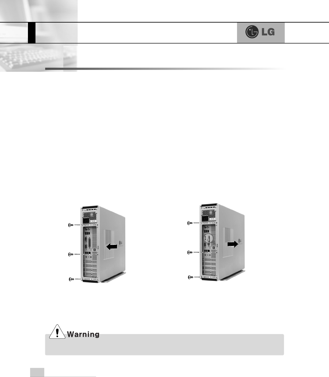
Remove 3 screws from the cover
and then push the cover as the
direction of the arrow
Push the cover in the direction of
arrow as it aligns the groove of
computer cover with body shown
on the picture and fasten 3 screws.
System Expansion 63
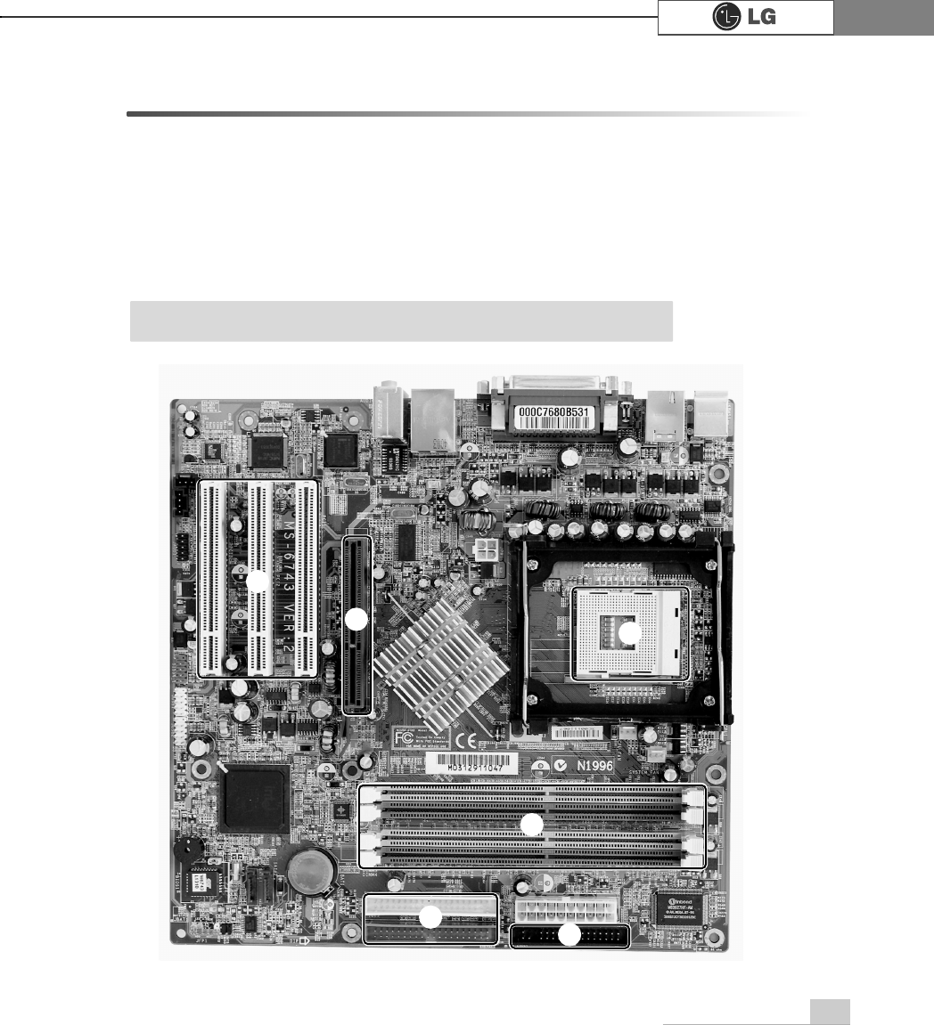
6-2. Main board
The main board determines the model name of your computer. Check the model
name on a label located at the rear of your computer before system expansion.
℘PCI slot
ℙ
ℙAGP slot
ℚCPU socket
ℛ
ℛMemory socket (DIMM)
ℜFloopy disk connector
ℝ
ℝHard disk/CD-ROM connector
ก
ข
ฃ
ฅค
ãThe main board in your computer may look different from the picture.
Note
System Expansion64
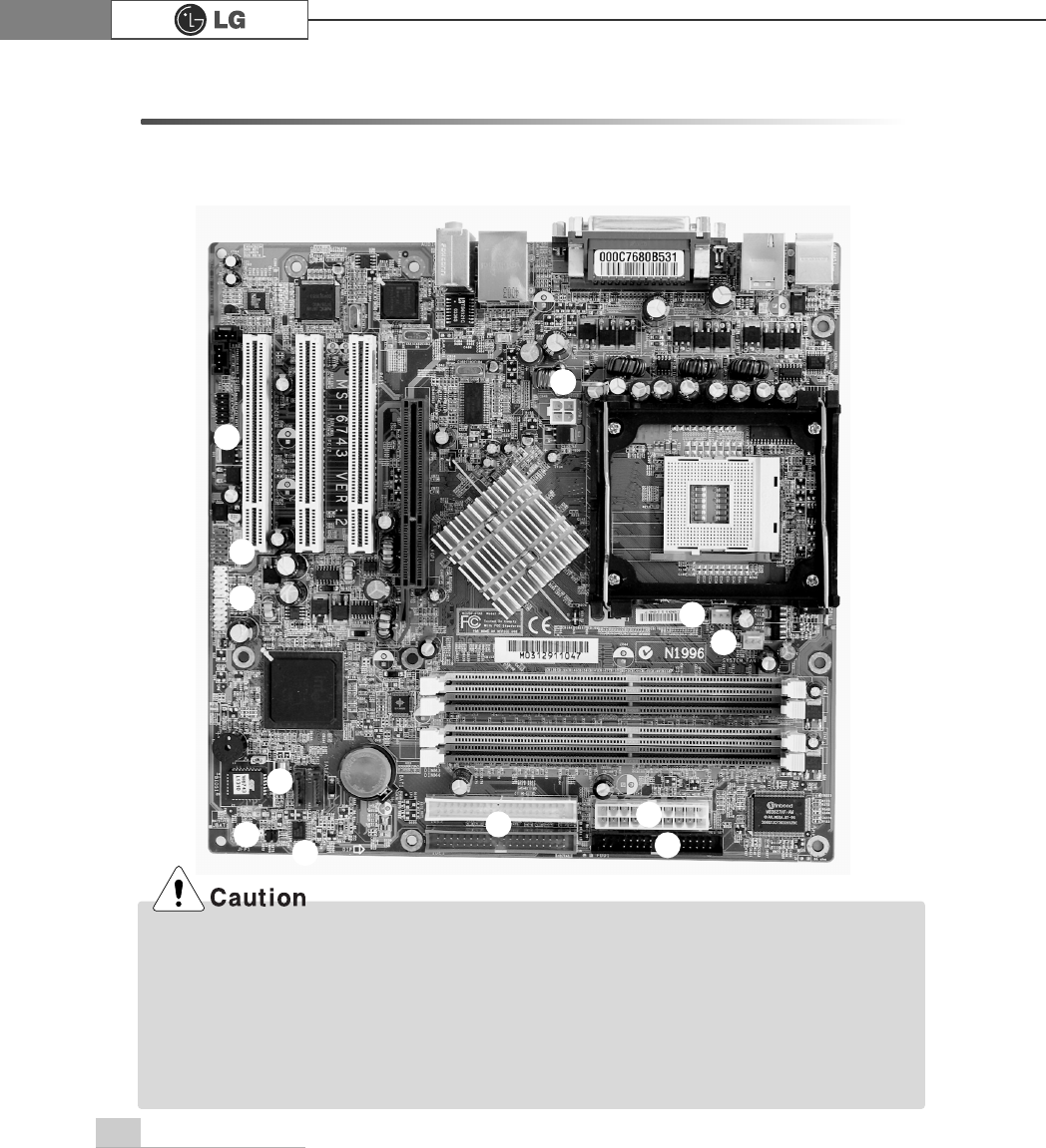
6-3. Connectors
The peripheral devices are connected to the main board through the connectors
shown below. (The main board in your computer may look different from the pic-
ture below)
ก
ข
ค
ฃ
ฆ
ฉ
จ
ง
ฅ
ãBefore removing the connector, check the status of connection and make a note.
ãAline the groove to the right direction when connecting floppy disk drive connector, hard
disk/CD-ROM connector.
ãMatch the pin number with the color of cable. There is a risk of disfunction to the computer.
ãThere is a risk of explosion if battery is replaced by an incorrect type. Dispose of used batter-
ies according to the instructions.
ãThere is a risk of explosion if the backup(standby) RTC battery is replaced by an incorrect type.
ãDispose of used backup(stadby) RTC battery according to your local ordinances or regulation.
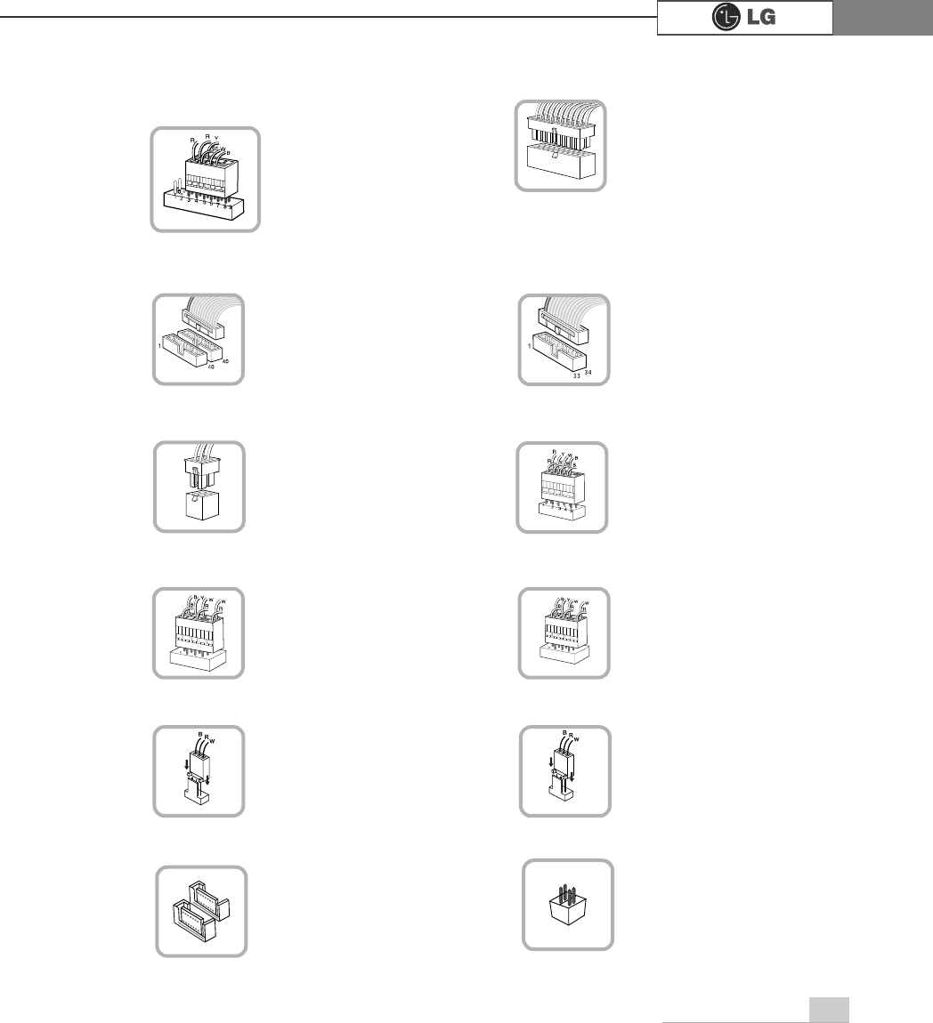
System Expansion 65
connects to the power
supply.
ℜPower connector(JPW1: 4 pins)
connects to the USB on
the front of the comput-
er.
ℝUSB connector(JUSB1: 10 pins)
JPW1 JUSB 1
,
connects to the IEEE
1394(6 pins) on the
front of the computer.
℞
IEEE
1394 connector
J1394
connects to the head-
phone and microphone
jacks on the front of the
computer.
℟Audio connector(JAUD1: 7 pins)
JAUD1
connects and supplies
power to the CPU fan.
℠CPU fan(CPU_FAN1: 3 pins)
CPU_FAN
If you are attaching only
one hard disk drive, be
sure to connect it to IDE1.
connects to the floppy
disk drive.
ℚHard disk/CD-ROM drive connectors
(IDE1, IDE2: 40 pins)
ℛFloppy disk drive connector
(FDD1: 34 pins)
IDE1 IDE2 FDD1
connects and supplies
power to the system
fan at the bottom of the
computer.
℡System fan (System_FAN1: 3 pins)
SYSTEM_FAN
connects
6$7$GHYLFH
⌅SATA connector
SATA
connects VFD.
⌆VFD connector
VFD
℘Power switch, power/ hard disk activity
LED connector (JFP1) connects to the power.
ℙPower connector (CONN1: 20 pins)
connects power switch
and hard disk activity
LED .
JFP1
ATX1
System Expansion66
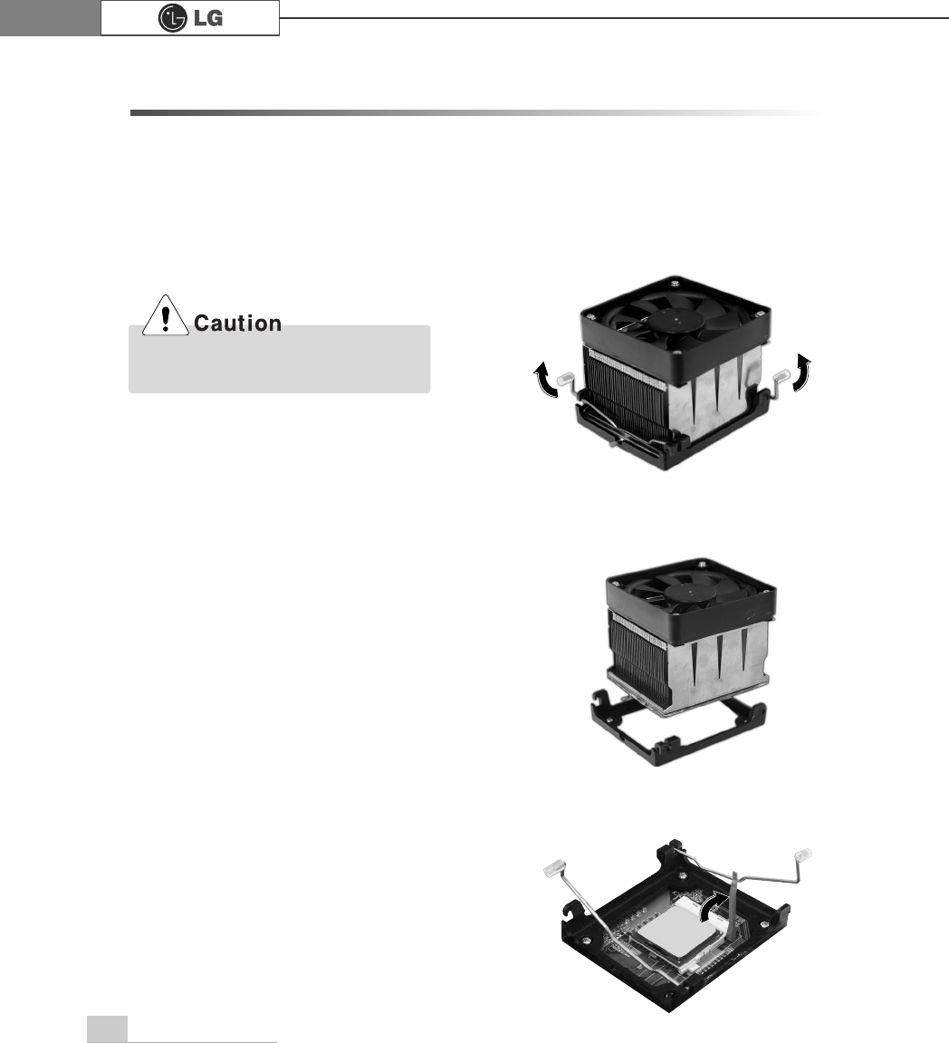
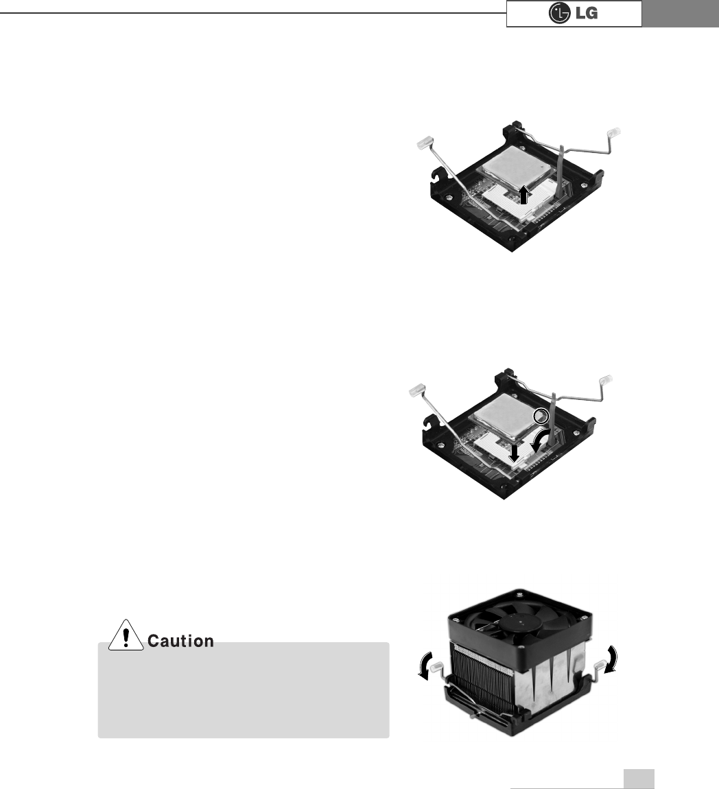
6-4 Replacing the CPU
You can replace and upgrade the CPU in your computer. Check the location and
type of the CPU on the main board.
*The shape and replacement method of the CPU fan may be different on the model.
ⓞ
Release the each latch by lifting it as the direction of the arrows.
ⓟ
Raise the handle on the socket to unlock the CPU.
ⓠLift the CPU straight up. Be careful not to damage the pins at the bottom of the CPU.
Consult your service representatives
before replacing the CPU
System Expansion 67
ⓡ
Align the identifying marks at the corners of the new CPU and socket, and care-
fully install the CPU in the socket.
ⓢ
Lower the handle on the socket to lock the CPU.
ⓣFasten the each latch by pushing it as the direction of the arrows.
In some models, you can not lower one of the
handles of the clamps all the way down. For
removing CPUs in these models, release the
clamp on the other side first. For installing CPUs
in these models, lock this clamp first.
System Expansion68
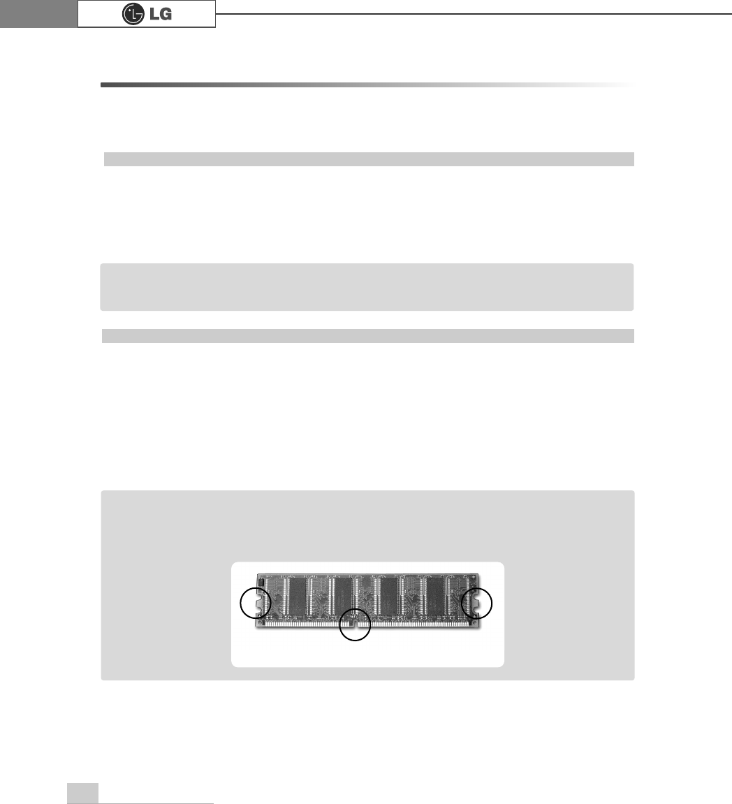
6-5. Increasing the memory
If you run out of memory while using the computer, you may want to increase the
amount of memory in your computer.
About memory
Your computer uses DDR(Double Data Rate) SDRAM DIMM(Dual In-Line Memory
Module) with 184 pins. Your computer supports Unbuffered DDR SDRAM DIMM of
256MB up to 512MB in size in each socket, and 2GB total.
Before increasing the memory
ãAlways wear gloves to avoid injury when disassembling the computer
ãStatic electricity can damage memory modules be sure to minimize the static
electricity when replacing memory.
ãMake sure to replace the memory of the same type as the installed memory.
ãDIMM is different from SIMM in that it is configured for 64 bit operation; therefore,
your computer can operate with only one DIMM installed.
ãWindows 95, 98SE, ME supports memory up to 512MB total. Increasing the memory
beyond 512MB in these systems may cause errors while using the computer.
Note
ãUse a 2.5V DDR SDRAM DIMM.(The shape of the memory may be different depending
on the model) DDR SDRAM enhances the rate of data transmission of the SDRAM and
looks different from SDRAM.
Note
DDR
System Expansion 69
Refer to the Memory configuration chart to increase the memory.
ãYour computer supports PC2700/3200 DDR memory.
ãUse Unbuffered DDR SDRAM DIMM only to increase the memory.
ãDual channel mode operates when each identical memory is installed in the same color
of DIMM slot.
FSB Frequency
533/800MHz
Supported memory type
PC2700/3200-DDR SDRAM 333/400MHz
Purchasing a memory
Check the type of memory installed in your computer and refer to the memory con-
figuration chart before purchasing a memory.
Specification: PC2700/3200(184 pin DDR SDRAM DIMM)
Speed: 333MHz(166MHz X 2), 400MHz(200MHz X 2)
Size: 256MB, 512MB
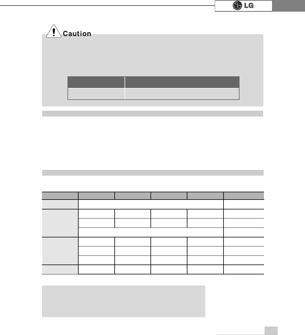
Memory configuration chart
Total memory DIMM 1 DIMM 2 DIMM 3 DIMM 4
DUAL/SINGLE
SINGLE
DUAL
DUAL
SINGLE
DUAL
DUAL
DUAL
DUAL
512MB
256MB 256MB
256MB 256MB
256MB
1024MB
256MB 256MB 256MB 256MB
512MB 512MB
512MB 512MB
2048MB 512MB 512MB 512MB 512MB
512 (One of 4 slots)
256 (One of 4 slots)
ãDual channel improves the efficiency of the system.
ãEach identical memory should be used for dual channel setting.
ãDual channel setting is recommended.
Note