LG Electronics USA DT-FG Personal Computer User Manual 46475FC7A5C1F62E717864
LG Electronics USA Personal Computer 46475FC7A5C1F62E717864
Contents
- 1. users manual A
- 2. users manual B
- 3. users manual C
- 4. users manual D
users manual D
System Expansion70
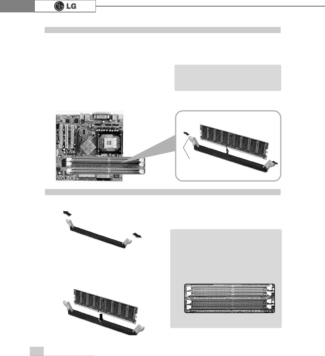
The main board configuration, memory socket, and the shape of memory may be
different depending on the model.
ⓞRemove the screws on the rear of the
computer, and open the computer case.
ⓟPull the latch on each side of a memory socket to release the memory.
Replacing the memory
latch
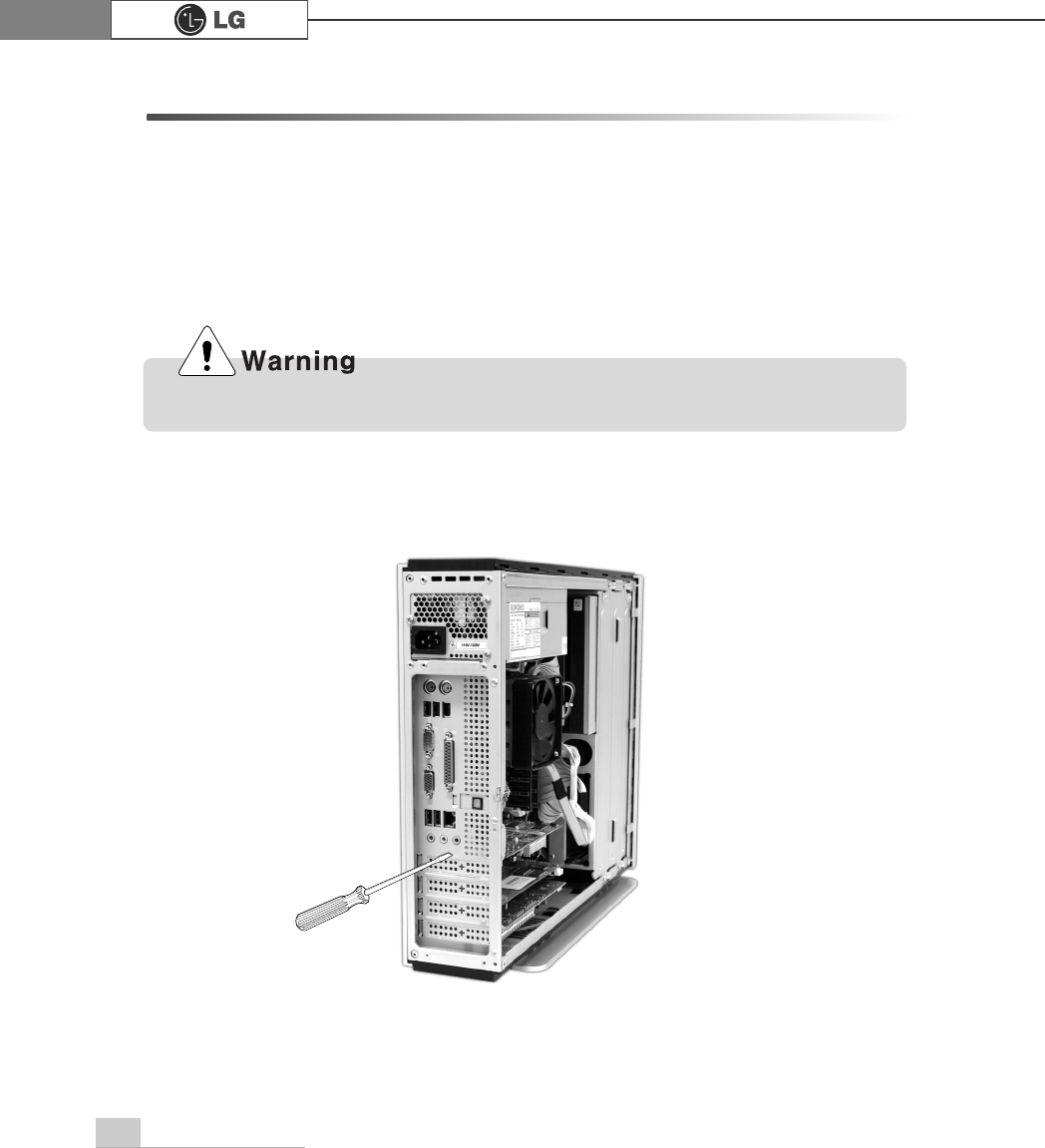
ãBefore opening the case, turn off the
computer and peripheral devices,
and remove the power cords.
Note
ⓞ
Pull the latch on each side of a memory socket.
ⓟ
Align the notch at the bottom of the
memory with a protrusion in the middle
of the socket, and then insert the
memory straight down.
Installing a memory
ãFor dual channel system, each mem
ory should be installed in independent
slot(1&3 slot or 2&4 slot) when using
DDR Memory
It is recognized as a single channel if
there is a difference between dual
channel 1 and 3, 2 and 4.
Note
℘
ℙ
ℚ
ℛ
Firmly push the latch to lock the memory.
System Expansion 71
Checking the size of the installed memory
The computer automatically recognizes the newly installed memory; therefore,
you do not need to change the system setup. Follow the instruction below to
check the size of the installed memory.
ⓞConnect the power cord and other devices, and turn on the computer and monitor.
The following screen appears to inspect the status of the computer.
ⓟIf the following screen appears, press [Esc]. POST screen appears.
ⓡAfter check the memory, press [Esc]. Windows screen appears.
ⓠIf the following screen appears, press [Pause] key to pause the screen. Make
sure [Memory Testing : XXXXXX OK] appears.
Award Modular BIOS vX.XXXX, An Energy Star Ally
Copyright(C) 1984-2004, Award Software, Inc.
Build ID : LG XXXX XX.XX XX:XX:XX
Main Processor : Intel(R) Pentium(R) X Processor XXXMHz
Memory Test : XXXXXX OK
Press DEL to enter SETUP
XX/XX/XX-XXXX-XXXX-XXXXXXXXX-XX
0HPRU\7HVWLQJ;;;;;;2.
ã
To stop the logo screen for a moment,
press [Delete] key ⎀Advanced BIOS
Features ⎀Full Screen Logo Show
Selectable, and then select Disable.
Note
System Expansion72
6-6. Adding a hard disk drive
Your computer supports up to 4 E-IDE controllers and 2 hard disk drives.
The following instruction describes the most typical configuration where your comput-
er already has a master hard disk drive and you are adding a slave hard disk drive.
ãAlways wear gloves to avoid injury when disassembling the computer.
ãIf the master hard drive is set to CS(Cable Select), the slave drive must also be set to
CS(Cable Select).
ãUsing screws other than the ones provided with the hard disk drive can damage the drive.
Using longer or thicker screws can be fatal to the disk drive. A hard disk drive must be
mounted securely in order to provide reliable performance.
Before adding a hard disk drive
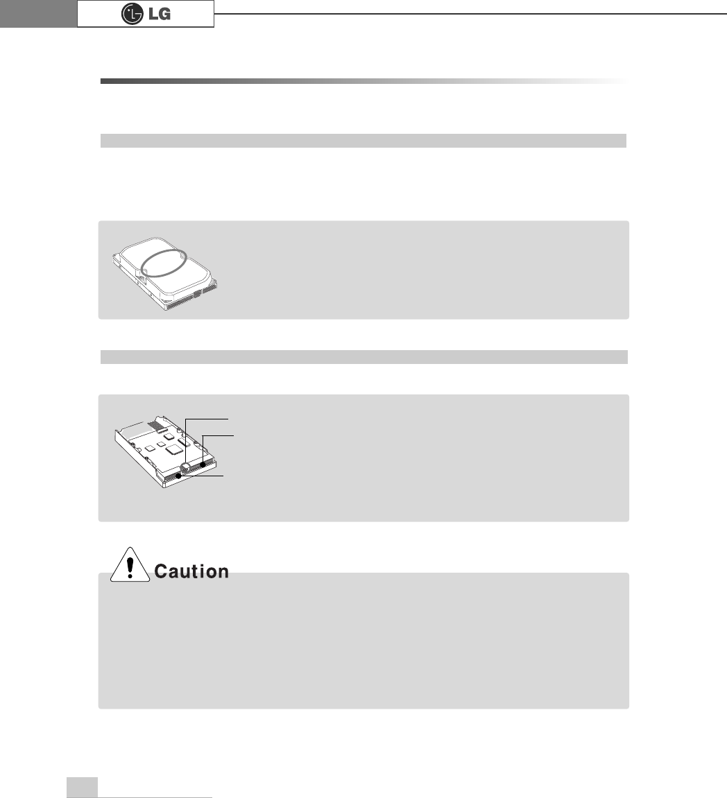
Adding a hard disk drive
ãCheck and write down the jumper settings, size, and number of
cylinders, heads, and sectors of the hard disk drive where you
can refer to when you use the system setup.
(Some hard disk drives do not have the information written on the drive)
Note
Note
Power connector
Signal cable
connector
Jumper ãPrepare the hard disk you want to add.
ãPurchase an E-IDE hard disk drive.
ãSet the jumper setting in the slave hard to SL: Slave.
ãThe jumper settings differ from one hard disk
drive to another, so make sure you follow the
jumper setting information on top of the drive.
System Expansion 73
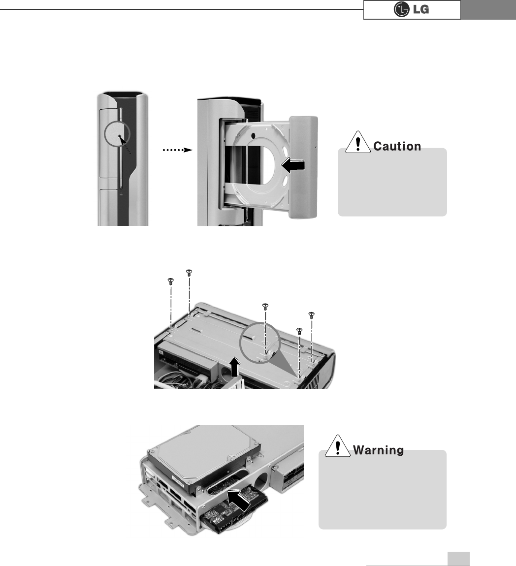
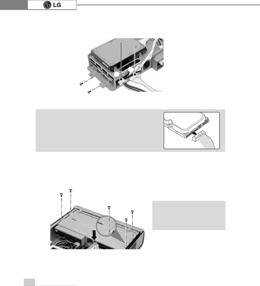
ⓟRefer to the page 62 to remove the cover. Remove the 4 screws from the hard
case and remove the case to the direction of the arrow.
ⓞOpen the CD-ROM drive by using a sharp pin into the emergency hole as shown
on the picture No ℘. Remove the by pushing it to the direction of the arrow as
shown on the picture No ℙ.
ⓠPush the new hard disk you want to replace with to the direction of the arrow.
℘ℙ
Turn off the computer and
remove the cable when
disassembling the com-
puter. There is a risk of an
electrical shock.
Check the connection
between the power cable
and the signal cable. There
is a risk of damage to the
computer and an electrical
shock.
System Expansion74
ⓡConnect the power cable connector and the signal cable connector to the new
hard disk you want to replaced with and fasten 2 screws in the hard disk case.
ⓢFasten 4 screws in the hard case after connecting the cables. Refer to the page
62 to close the cover. Install the CD-ROM tray.
power cable
℘
ℙ
ãAlign the connector in a right position as show on the
picture.
Actual appearance of the connector may be different
from the picture, check the right position.
Note
ãAfter installing the hard disk
you should setup and format
your system. Refer to the
Hard disk setup on page 77.
Note
signal cable
System Expansion 75
ⓞTurn on the computer and monitor.
ⓟ
Press [Delete]key when the logo screen appears.
ⓠThe CMOS Setup Utility opens.
ⓡ
Use arrow
>Ⓑ@>Ⓒ@>⒵@
, and
>Ⓐ@
keys to select Standard CMOS Features, and
press Enter.
Hard disk drive setup
3KRHQL[$ZDUG%,26&0266HWXS8WLOLW\
Ě 6WDQGDUG&026)HDWXUHV Ě
3&+HDOWK6WDWXV
Ě $GYDQFHG%,26)HDWXUHV Ě )UHTXHQF\9ROWDJH&RQWURO
Ě $GYDQFHG&KLSVHW)HDWXUHV /RDG2SWLPL]HG'HIDXOWV
Ě ,QWHJUDWHG3HULSKHUDOV 6HW3DVVZRUG
Ě 3RZHU0DQDJHPHQW6HWXS 6DYH([LW6HWXS
Ě 3Q33&,&RQILJXUDWLRQV ([LW:LWKRXW6DYLQJ
(VF4XLW êëè é 6HOHFWOWHP
)6DYH([LW6HWXS
9LUXV3URWHFWLRQ%RRW6HTXHQFH
System Expansion76
ⓢ
Use arrow
>Ⓑ@>Ⓒ@>⒵@
, and
>Ⓐ@
keys to select IDE Channel 0 Slave, and press
[Enter].
ⓣ
After setting IDE Channel 0 Slave to Auto by pressing [Enter], press [Enter] in
IDE HDD Auto-Detection so the system automatically recognizes the newly
installed slave hard disk drive.
ⓤPress [F10] to save the new setting.
ⓥIf the following message appears, press [Enter]. The computer restarts.
Data (mm:dd:yy) XXX, XXX, XXXX
Time (hh:mm:ss) XX, XX, XX
ĚIDE Channel 0 Master Press EnterXXXXXMB
ĚIDE Channel 0 Slave Press Enter None
ĚIDE Channel 1 Master Press Enter None
ĚIDE Channel 1 Slave Press Enter None
Drive A X.XXM, X.Xin
Drive B None
Video EGA/VGA
Halt On All, But Keyboard.
CPU Type X.XXX.XXX.XX
BIOS Version Build ID :LG
Video Memory X.XX K
System Memory X.XX K
Total Memory X.XX K
Item Help
Menu Level Ě
Press [Entre] to enter
next page for detail
this drive settings
êëèé:Move Enter:Select +/-/PU/PD:Value F10:Save ESC:Exit F1:General Help
F5:Previous Values F7:Optimized Defaults
Press Enter None
Ě
IIDE Channel 0 Slave
IDE HDD Auto-Detection
Press Enter
IDE Channel 0 Slave Auto
Access Mode Auto
Capacity 0 MB
Cylinder 0
Head 0
Precomp 0
Lauding Zome 0
Sector 0
Item Help
Menu Level Ě
To auto-detect the
HDD±s size, head...on
this channel
êëèé:Move Enter:Select +/-/PU/PD:Value F10:Save ESC:Exit F1:General Help
F5:Previous Values F7:Optimized Defaults
$XWR
3UHVV(QWHU
SAVE to CMOS and EXIT(Y/N)? Y
Phoenix-Award BIOS CMOS Set up Utility
IDE Channel 0 Slave
Phoenix-Award BIOS CMOS Set up Utility
Standard CMOS Features
System Expansion 77
Hard disk setup (Hard disk with factory default setting)
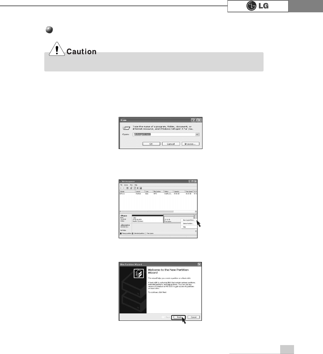
ⓞClick [Start] and [Run].
ⓟType 'diskmgmt.msc' and press [OK].
ⓠIf the following window appears, select disk1. Click right button on the mouse to
select New partition.
ⓡClick [Next] if the following message appears.
Be careful, Using <diskmgmt.msc> to divide partition delete data in a selected driver.
78 System Expansion
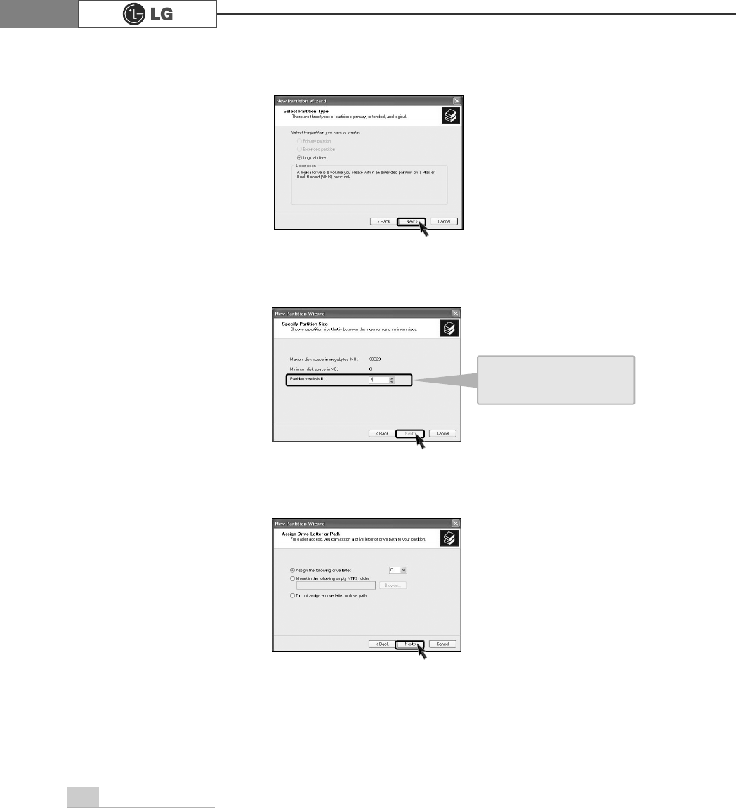
ⓢSelect a partition and click [Next].
ⓣSelect the maximum size and click [Next].
ⓤClick [Next] after selecting a drive value.
A selected space of the
disk will be available to
use.
79System Expansion
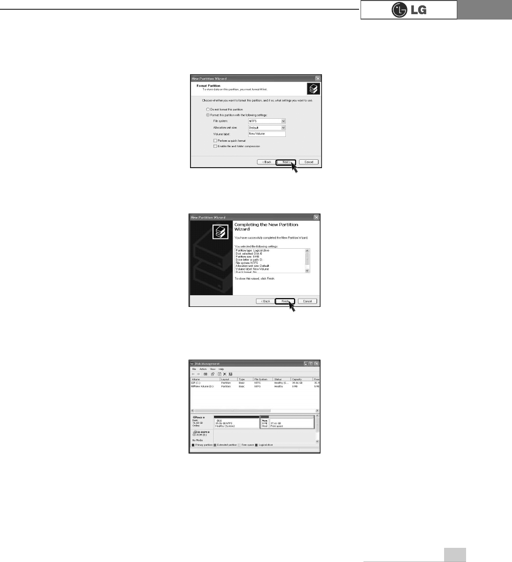
ⓥIf the following window appears, select File system, Allocation unit size and
Volume label ,and click [Next].
ⓦNew Partition Wizard is complete, click [Finish].
ⓧAfter the format is complete, the hard disk operates normally.
80 System Expansion
6-7.Installing expansion cards
When you are using the computer, you may need to install expansion cards to
improve funtionality. The following instruction describes how to install expansion
cards.
ⓞRefer to Opening the computer case to open the computer case cover.
ⓟ
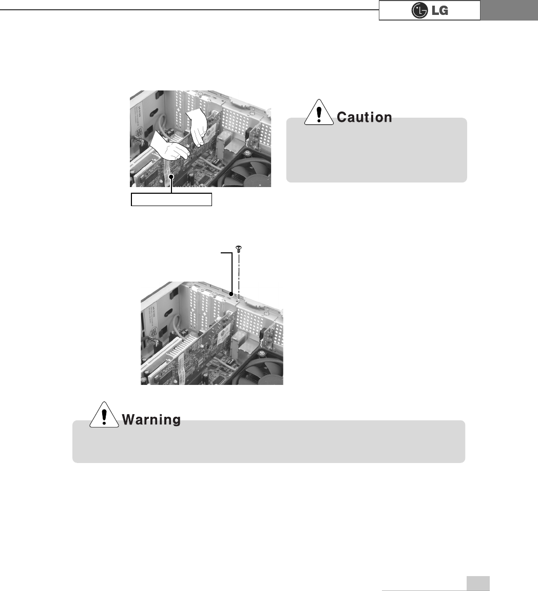
Remove 3 screws as shown on the picture Remove the slot using driver where
the expension card is located.(Remove the slot when expansion card is installed )
Always use a screwdriver to open the case cover. There is the risk of injury.
81System Expansion
Metal bracket
Using the computer without closing the case may result in fire, electric shock,
injury, and/or damage to the computer.
Incorrect installation of an expan-
sion card may damage the main
board and result in a computer
malfunction.
ⓠ
Hold the expansion card with both hands and align the expansion card and slot.
Push down evenly to insert the card into the slot.
ⓡ
Fasten a screw to fasten the metal bracket of the card to the computer case.
ⓢ
Refer to Closing the computer case page 64 to close the case cover of the
computer.
ⓣ
Install the driver program for the new expansion card.
Expansion slot

Specifications82
Specifications *
)*PRGHO
Multi-memory card slot CF/MD/MS/MS-Pro/SD/MMC/SMC card supported in the front pannel.
Keyboard PS/2 keyboard (104keys)
Mouse PS/2 mouse or USB (ball / wheel)
Video Integrated or external AGP graphic
Sound Built-in AC'97 audio. Support MIC-IN, SPEAKER-OUT and
LINE-IN.(Support virtual 5.1 channel output)
System memory
Cache memory L1: 8KB/16KB or above, L2: 128KB/256KB/512KB/1024KB or
above.
Hard disk drive 40GB or above (E-IDE type)
LAN Integrated 10/100Base-T Ethernet
USB 6ports (support USB 2.0)
Serial I/O One RS-232C (9pins)
Parallel I/O One printer port (25pins)
IEEE1394 One IEEE1394
Front I/O Two USB ports and audio ports (SPEAKER-OUT and MIC-IN)
Extension slot Three PCI slots, one AGP slot and four memory DIMM slots
Product size Width 100 x Height 365 x depth 460(mm)
Cable Power cable length 1.8m
Power spec 100~127 / 200~240VAC, 5A / 4A, 50/60Hz or
200~240VAC. 4A, 50/60Hz
CPU Intel Pentium 4 / Celeron mPGA478 type (2.4GHz or above)
ÚÚSpecifications below differ depending on the models.
256MB (up to 2.0 GB) - If built-in VGA is used, maximum 16MB
and minimum 1MB is applied for Video Frame buffer in DOS
Mode, but Windows Mode automatically manages the video
memory (up to 96MB depending on System Memory size).
Temperature:Average temperature:77ĕ(25Ë
Operating temperature:41ĕ~95ĕ(5~35Ë
Storage temperature:-4ĕ~131ĕ
-25~55Ë
Humidity:Average humidity:60%(RH)
Operating humidity:30%~80%(RH)/Storage humidity:30%~80%(RH)
Environmental
requirement

84 memo
PHPR