Landis Gyr Technology EG0R3S2 GAS METER TRANSMITTER MODULE User Manual USERS MANUAL 4
Landis+Gyr Technology, Inc. GAS METER TRANSMITTER MODULE USERS MANUAL 4
Contents
- 1. USERS MANUAL 2
- 2. USERS MANUAL 1
- 3. USERS MANUAL 3
- 4. USERS MANUAL 4
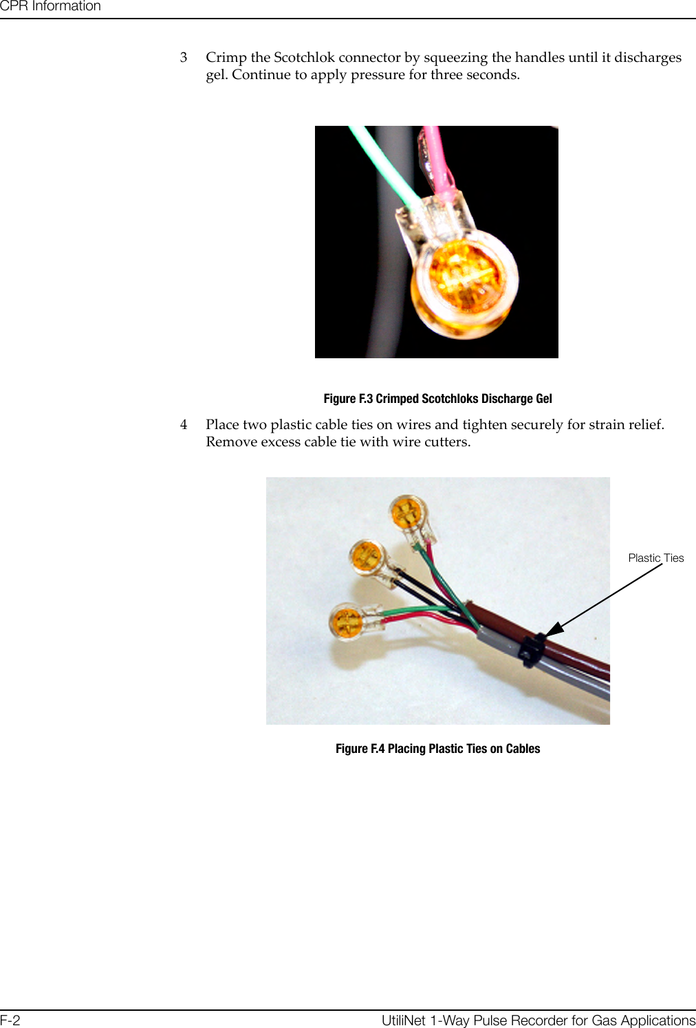
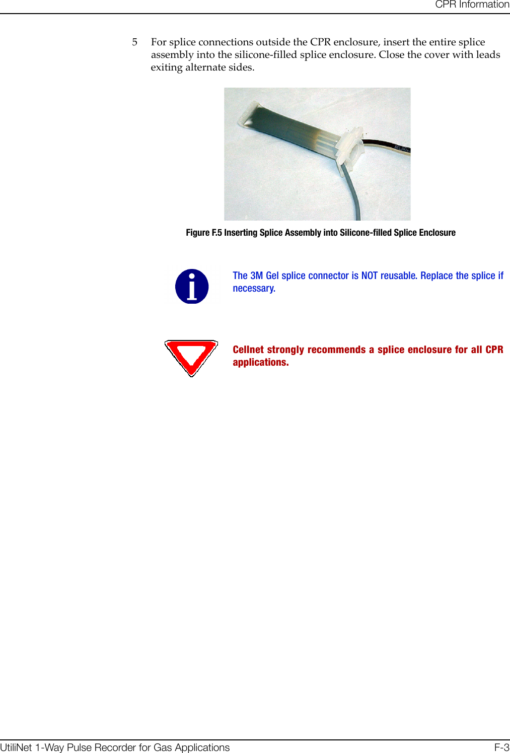
USERS MANUAL 4


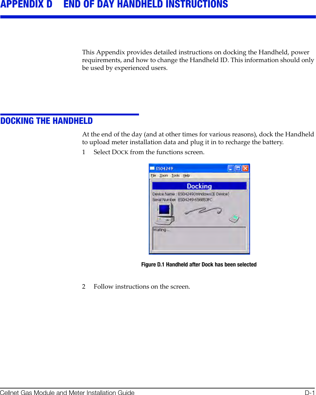
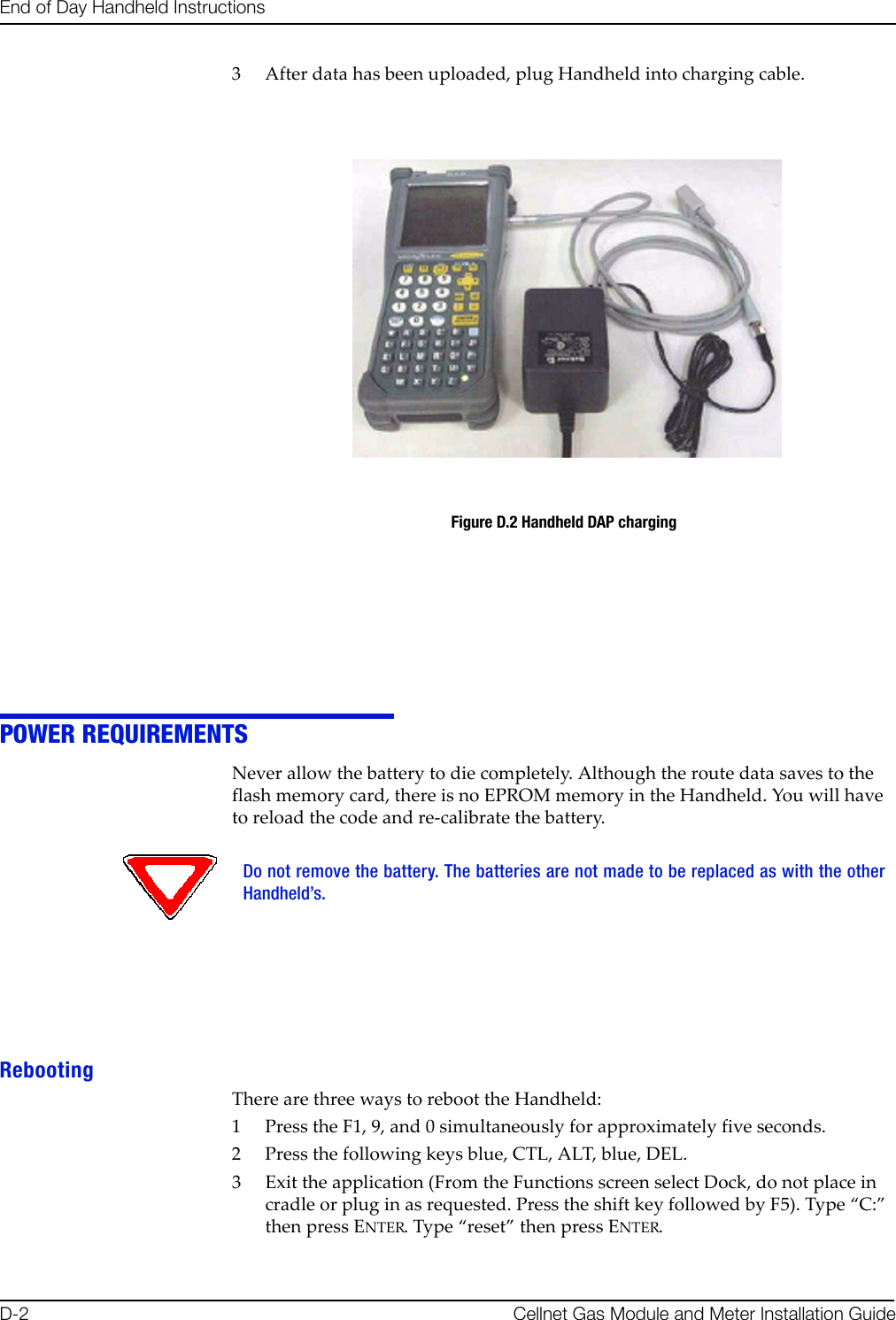
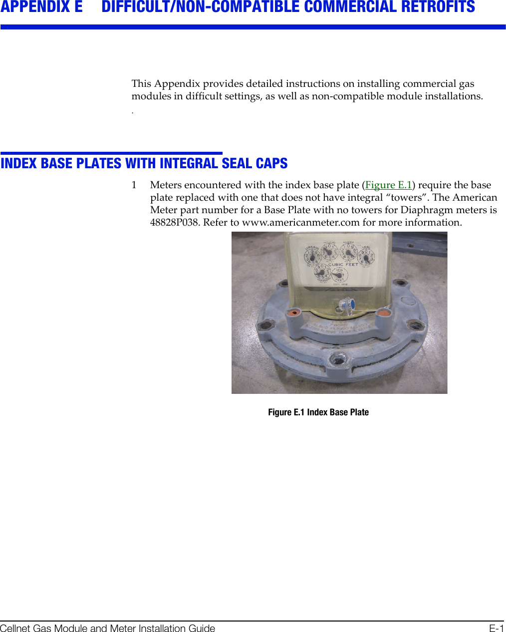
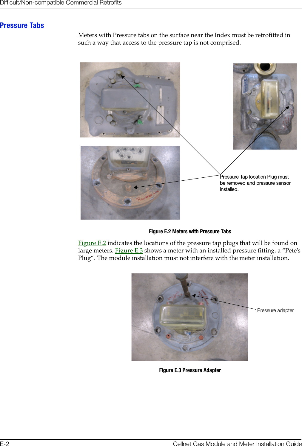
![båÇ=çÑ=a~ó=e~åÇÜÉäÇ=fåëíêìÅíáçåë`ÉääåÉí=d~ë=jçÇìäÉ=~åÇ=jÉíÉê=fåëí~ää~íáçå=dìáÇÉ aJPHOW TO CHANGE THE HANDHELD ID OccasionallytheHandheldIDmaybeenteredincorrectlyorthewrongHandheldIDmaybeinaHandheldbecauseofamemorycardexchange.ThissectiontellshowtochangetheHandheldIDtothecorrectnumber.1PlacetheHandheldinthecradleanddockit.2OpenupthemostrecentversionofHandheldEdit.3Select“Communication”then“TransferFiles”fromthemenuonHandheldEdit.4Ontherightsideofthepopupwindow,doubleclickonthe[CELLNET]folder.5SelectUnitinfo.datanddeleteit.Select“Yes”toverifythatyouwanttodeletethefile.6Select“OK”onthepopupwindowandcloseHandheldEdit.7TheHandheldwillthenpromptyoutoenterthelast4digitsoftheserialnumberonthebackoftheHandheld.8BeforeusingtheHandheld,makesuretheproperrouteinformationisloadedintotheHandheld.KNOWN COMMON PROBLEMS•IftheHandheldgetsjarred,thememorycardmaybecomedislodgedslightly.Thismakesitlooklikeallofthedatahasbeenlost‐butitisstillthere.UnscrewthetwoscrewsatthetopoftheHandheldbelowtheInfra‐redscanner.Re‐seatthecardandre‐tightenthecover.Youmayneedtore‐boottheHandheld.•Ifthebluekeyandthenoneofthearrowkeysispushed,partofthescreenseemstodisappear.Thescreenwasdesignedtoholdmoredata.Bluekey+arrowishowyoushiftthescreentoviewthatdata.Pushthebluebuttonandthearrowkeyintheoppositedirectionofthescreenshift.](https://usermanual.wiki/Landis-Gyr-Technology/EG0R3S2.USERS-MANUAL-4/User-Guide-922998-Page-12.png)


![Reader’s Comment FormCellnetGasMeterandModuleInstallationGuide(CO‐0089‐GB‐07.07)Pleaseusethisformonlytoidentifypublicationerrorsortorequestchangesinpublications.Yourcommentsassistusinimprovingourpublications.Directanyrequestsforadditionalpublications,technicalquestionsaboutsystems,changesinsupport,andsoon,toyourCellnetsalesrepresentative.Youmustusethisformtocommunicateyourcommentsaboutthispublication,itsorganization,orsubjectmatter,withtheunderstandingthatwemayuseordistributewhateverinformationyousupplyinanywaywebelieveappropriatewithoutincurringanyobligationtoyou.Youcansendcommentsviaemail,conventionalmail,orfax.Ifyourcommentdoesnotneedareply(forexample,pointingoutatypingerror),checkthisboxanddonotincludeyournameandaddressbelow.Ifyourcommentisapplicable,wewillincludeitinthenextrevisionofthemanual.Ifyouwouldlikeareply,checkthisbox.Besuretoprintyournameandaddressbelow.(Pleaseprint.)To send your comments via... Use this contact information...bã~áä ÅìëíçãÉêëìééçêí]ÅÉääåÉíKÅçã`çåîÉåíáçå~ä=ã~áä `ÉääåÉíI=PMMMM=jáää=`êÉÉâ=^îÉKI=pìáíÉ=NMMI=^äéÜ~êÉíí~I=d^=PMMOOc~ñ ESTUF=ORUJNRRMPage CommentsDate CompanyNameYourName MailingAddressPhoneNo.Email](https://usermanual.wiki/Landis-Gyr-Technology/EG0R3S2.USERS-MANUAL-4/User-Guide-922998-Page-27.png)