Landis Gyr Technology EG0R3S2 GAS METER TRANSMITTER MODULE User Manual USERS MANUAL 4
Landis+Gyr Technology, Inc. GAS METER TRANSMITTER MODULE USERS MANUAL 4
Contents
- 1. USERS MANUAL 2
- 2. USERS MANUAL 1
- 3. USERS MANUAL 3
- 4. USERS MANUAL 4
USERS MANUAL 4

5015 B.U. Bowman Drive Buford, GA 30518 USA Voice: 770-831-8048 Fax: 770-831-8598
Certification Exhibit
FCC ID: R7PEG0R3S2
IC: 5294A-EG0R3S2
FCC Rule Part: 15.247
IC Radio Standards Specification: RSS-210
ACS Report Number: 07-0243-15C
Manufacturer: Cellnet Technology, Inc.
Model(s): 25-1075, 25-1080, 25-1081
Manual
(Part 4 of 4)
`ÉääåÉí=d~ë=jçÇìäÉ=~åÇ=jÉíÉê=fåëí~ää~íáçå=dìáÇÉ _JN
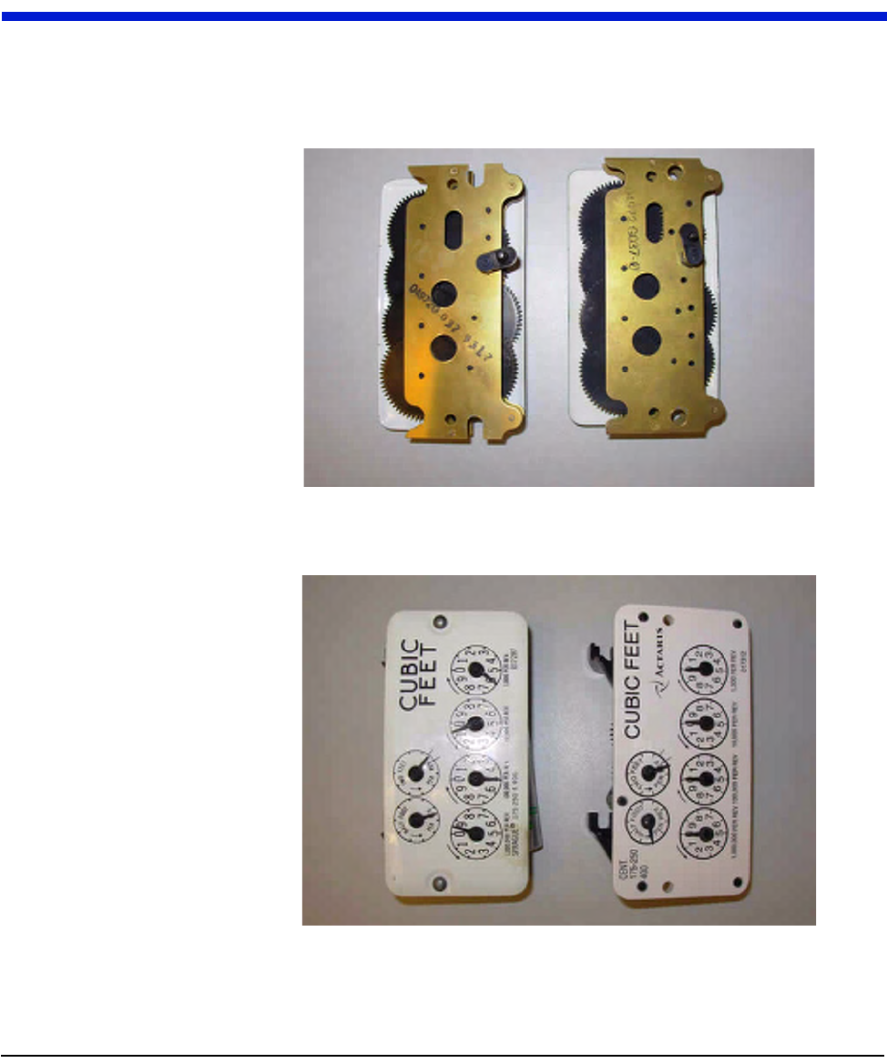
APPENDIX B VISUAL INSPECTION OF INDEXES
TheAmericanIndexonfarrightshowssignsoffadingfromglossyblacktoagrey
blackcolor,inthiscasetheIndexMUSTBEEXCHANGED.
Figure B.1 Fading American Index
OnaSpraguemeterifmetalrivetsarefoundontheindexplateasshownonthe
farlefttheIndexMUSTBEEXCHANGED.
Figure B.2 Metal rivets on a Sprague cover

Notes:
_JO `ÉääåÉí=d~ë=jçÇìäÉ=~åÇ=jÉíÉê=fåëí~ää~íáçå=dìáÇÉ
sáëì~ä=fåëéÉÅíáçå=çÑ=fåÇÉñÉë

`ÉääåÉí=d~ë=jçÇìäÉ=~åÇ=jÉíÉê=fåëí~ää~íáçå=dìáÇÉ `JN
APPENDIX C USING THE RF BUSTER
ThisAppendixprovidesdetailedinstructionsontheproperuseoftheRFBuster.
ItcoverstheproperplacementoftheRFBustertoensureactivationand
troubleshootingforCellnetgasmodules.
REQUIRED TOOLS
RFBuster‐partnumber26‐1050
BeforeusingtheRFBuster,testit.PressthebuttonontheRFBuster.TheRF
Buster’sLEDlightsred,andtheinternalspeakersoundsforapproximately½
second.Ifnothinghappens,oriftheLEDlightsandthespeakersounds
continuously,the9Vbatterymaybelow.Replaceit.
rëáåÖ=íÜÉ=oc=_ìëíÉê
`JO `ÉääåÉí=d~ë=jçÇìäÉ=~åÇ=jÉíÉê=fåëí~ää~íáçå=dìáÇÉ
RESIDENTIAL METER MODULES
American Modules
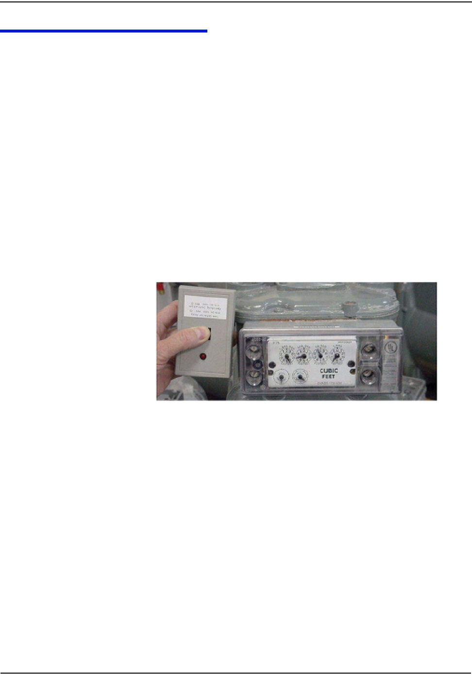
1PressthebuttonwiththelightfacingyouonthelowerendoftheRFBuster.
2PlacethecorneroftheRFBustercontainingthemagnetbythelocationofthe
ReedSwitchontheMeterModule.
3 Continuetopressthebutton.HoldtheRFBusterwithinaboutsixinchesof
themeter.ThemagnettriggerstenRFtransmissionsfromthegasmodule,
separatedbyonesecondeachtransmission.TheRFBusterLEDlightsredand
theinternalspeakersoundsapproximately½secondforeachtransmission
detected.
IftheRFBusterdoesnotdetectatransmissionfromthemodule,removethefour
coverscrewsandplacetheRFBusterintheproperlocation.Whilepressingthe
PushButton,pullthecoveroffthemodule.
•Ifthemoduleisfunctional,ittransmits.
IftheRFBusterdoesnotrespond,considerthemoduledefectiveandfollow
theappropriateprocedure.
Figure C.1 American proper placement of RF Buster
Rockwell/Equimeter/Sensus Modules
1PressthebuttonwiththelightfacingyouonthelowerendoftheRFBuster.
2PlacethecorneroftheRFBustercontainingthemagnetbythelocationofthe
ReedSwitchonthegasmetermodule.
3 Continuetopressthebutton.HoldtheRFBusterwithinaboutsixinchesof
themeter.ThemagnettriggerstenRFtransmissionsfromthegasmeter
module,separatedbyonesecondeachtransmission.TheRFBusterLED
lightsredandtheinternalspeakersoundsapproximately½secondforeach
transmissiondetected.
rëáåÖ=íÜÉ=oc=_ìëíÉê
`ÉääåÉí=d~ë=jçÇìäÉ=~åÇ=jÉíÉê=fåëí~ää~íáçå=dìáÇÉ `JP
IftheRFBusterdoesnotdetectatransmissionfromthemodule,removethefour
coverscrewsandplacetheRFBusterintheproperlocation.Whileholdingthe
PushButton,pullthecoveroffofthemodule.
•Ifthemoduleisfunctional,ittransmits.
•IftheRFBusterdoesnotrespond,considerthemoduledefectiveandfollow
theappropriateprocedure.
Figure C.2 Rockwell/Equimeter/Sensus RF Buster placement
Sprague/Schlumberger/Actaris Modules
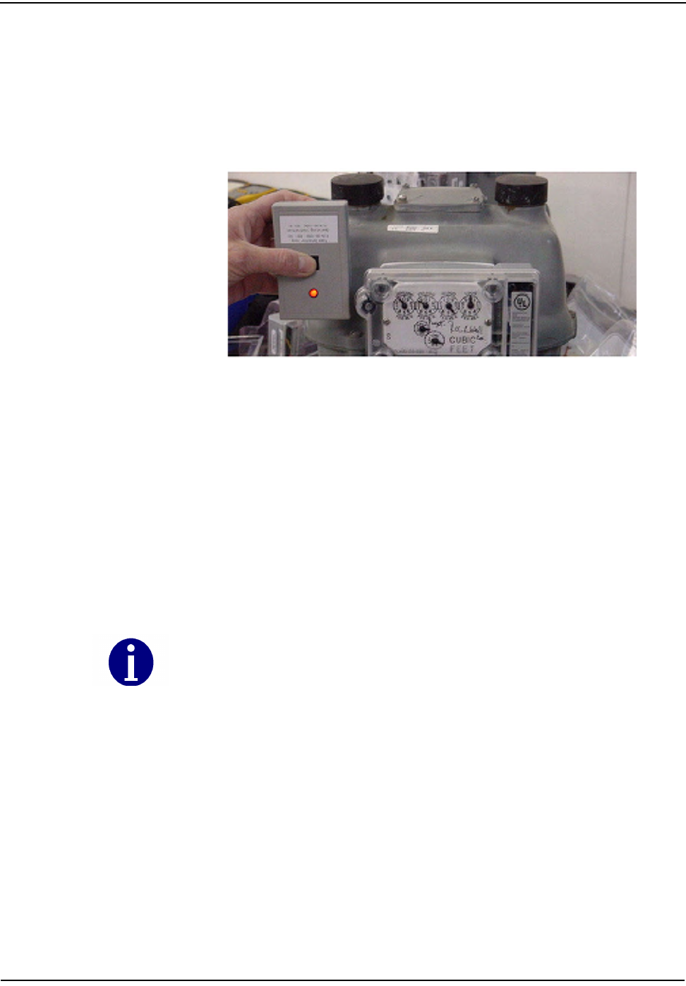
1PressthebuttonwiththelightfacingyouonthelowerendoftheRFBuster.
2PlacethecorneroftheRFBustercontainingthemagnetatananglebythe
locationoftheReedSwitchonthegasmetermodule(topleftcorner).
3 Continuetopressthebutton.HoldtheRFBusterwithinaboutsixinchesof
themeter.ThemagnettriggerstenRFtransmissionsfromthegasmeter
module,separatedbyonesecondeachtransmission.TheRFBusterLED
lightsredandtheinternalspeakersoundsapproximately½secondforeach
transmissiondetected.
IftheRFBusterdoesnotdetectatransmissionfromthemodule,removethetwo
coverscrewsandplacetheRFBusterintheproperlocation.Whileholdingthe
PushButton,pullthecoveroffofthemodule.
•Ifthemoduleisfunctional,ittransmits.
Because of the proximity of the different switches on the Sprague Module board,
ensure that you approach the module from the top left corner as seen in the
picture below.
rëáåÖ=íÜÉ=oc=_ìëíÉê
`JQ `ÉääåÉí=d~ë=jçÇìäÉ=~åÇ=jÉíÉê=fåëí~ää~íáçå=dìáÇÉ
•IftheRFBusterdoesnotrespond,considerthemoduledefectiveandfollow
theappropriateprocedure.
Figure C.3 Sprague/Schlumberger/Actaris RF placement
rëáåÖ=íÜÉ=oc=_ìëíÉê
`ÉääåÉí=d~ë=jçÇìäÉ=~åÇ=jÉíÉê=fåëí~ää~íáçå=dìáÇÉ `JR
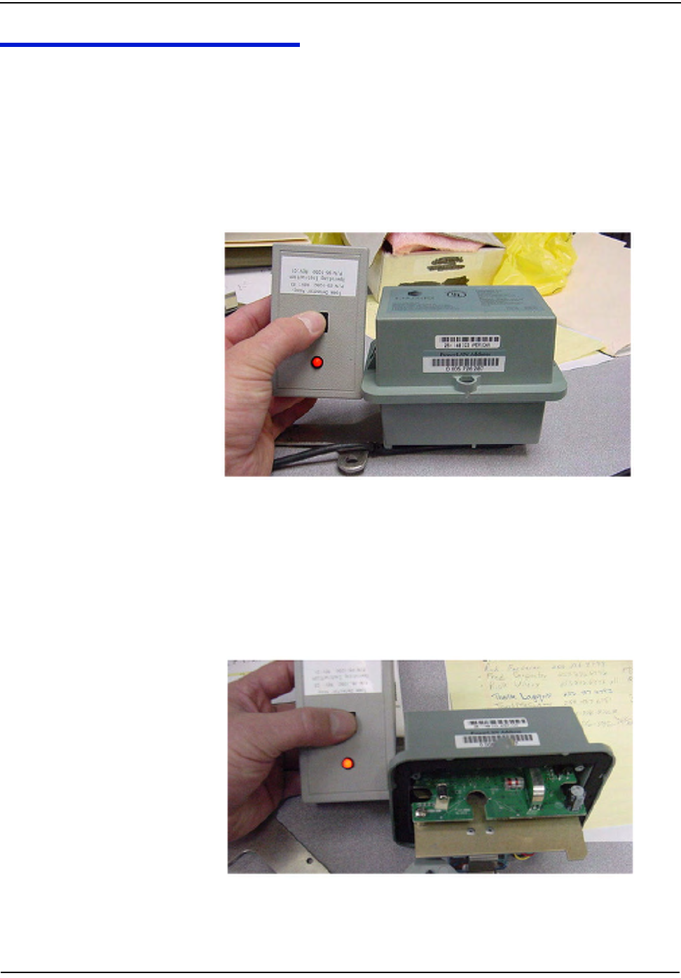
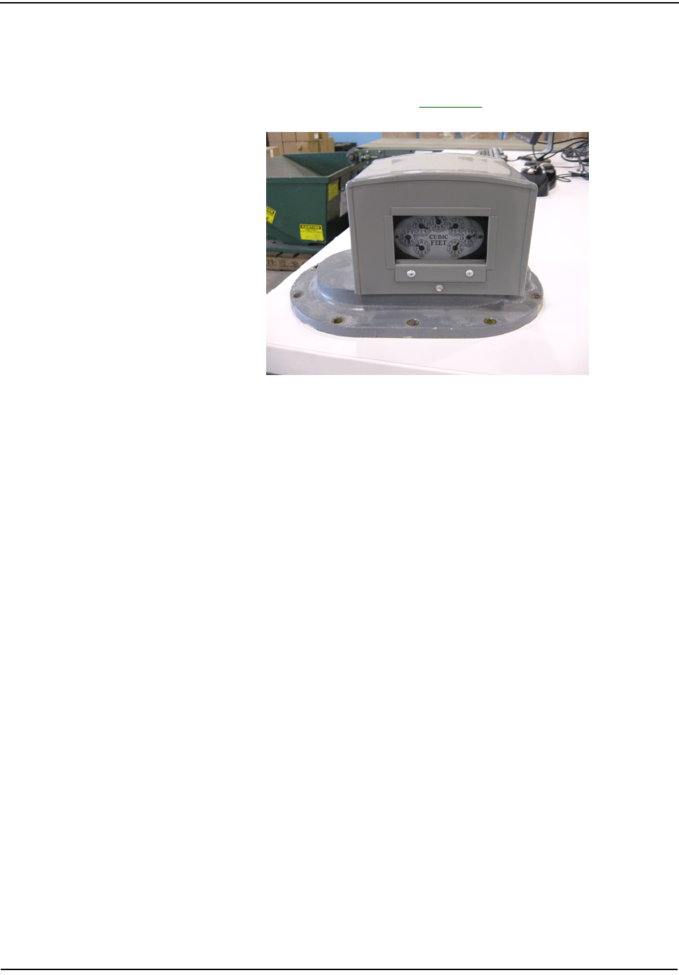
COMMERCIAL GAS 3 METER MODULES
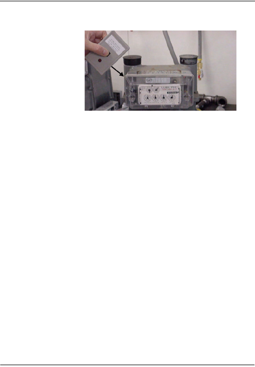
1PressthebuttonwiththelightfacingyouonthelowerendoftheRFBuster.
2PlacethecorneroftheRFBustercontainingthemagnetbythelocationofthe
ReedSwitchontheMeterModule.
3 Continuetopressthebutton.HoldtheRFBusterwithinaboutsixinchesof
themeter.ThemagnettriggerstenRFtransmissionsfromtheRFBuster,
separatedbyonesecondeachtransmission.TheRFBusterLEDlightsredand
theinternalspeakersoundsapproximately½secondforeachtransmission
detected.
Figure C.4 Commercial Gas RF placement
IftheRFBusterdoesnotdetectatransmissionfromthemodule,removethefour
coverscrewsandthecoverandplacetheRFBusterintheproperlocationwhile
pressingthePushButton.
IftheRFBusterdoesnotrespond,considerthemoduledefectiveandfollowthe
appropriateprocedure.
Figure C.5 Commercial Gas Module uncovered
rëáåÖ=íÜÉ=oc=_ìëíÉê
`JS `ÉääåÉí=d~ë=jçÇìäÉ=~åÇ=jÉíÉê=fåëí~ää~íáçå=dìáÇÉ
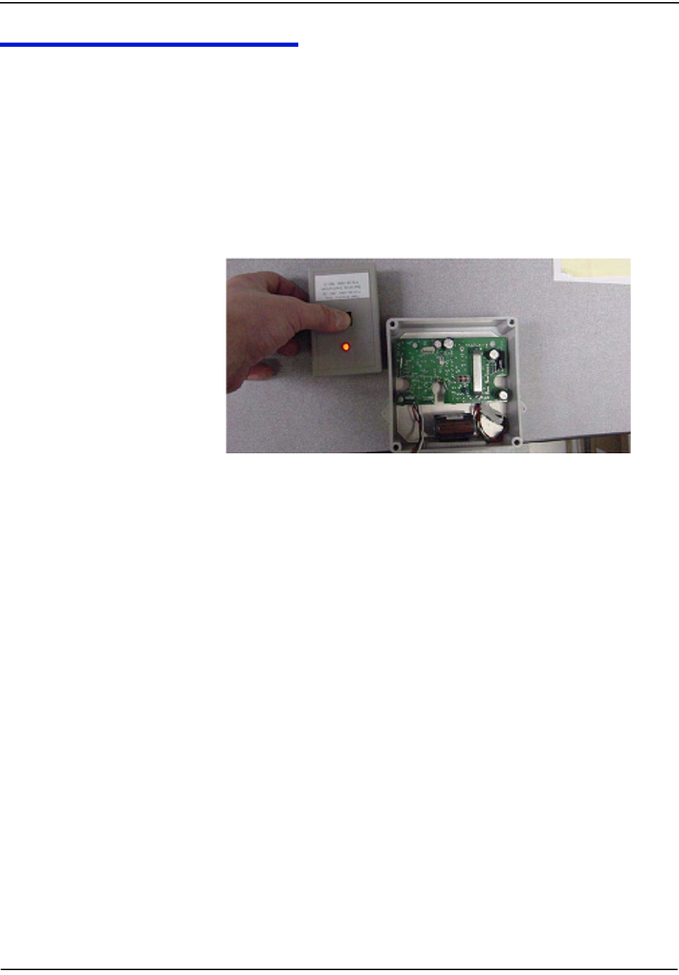
ROOTS/ROMETS ROTARY CPR MODULE
1PressthebuttonwiththelightfacingyouonthelowerendoftheRFBuster.
2PlacethecorneroftheRFBustercontainingthemagnetbythelocationofthe
ReedSwitchontheCPR.
3 Continuetopressthebutton.HoldtheRFBusterwithinaboutsixinchesof
theCPR.ThemagnettriggerstenRFtransmissionsfromtheCPR,separated
byonesecondpertransmission.TheRFBusterLEDlightsredandthe
internalspeakersoundsapproximately½secondforeachtransmission
detected.
Ifthereisnoresponse,removethecoveroftheCPRforproperorientation.
Figure C.6 ROOTS/Romets RG3 RF placement
`ÉääåÉí=d~ë=jçÇìäÉ=~åÇ=jÉíÉê=fåëí~ää~íáçå=dìáÇÉ aJN
APPENDIX D END OF DAY HANDHELD INSTRUCTIONS
ThisAppendixprovidesdetailedinstructionsondockingtheHandheld,power
requirements,andhowtochangetheHandheldID.Thisinformationshouldonly
beusedbyexperiencedusers.
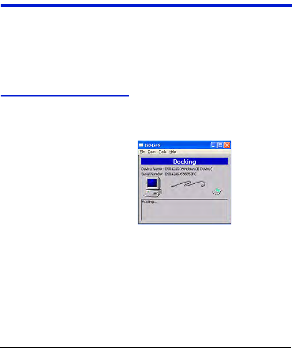
DOCKING THE HANDHELD
Attheendoftheday(andatothertimesforvariousreasons),docktheHandheld
touploadmeterinstallationdataandplugitintorechargethebattery.
1SelectDOCKfromthefunctionsscreen.
Figure D.1 Handheld after Dock has been selected
2Followinstructionsonthescreen.
båÇ=çÑ=a~ó=e~åÇÜÉäÇ=fåëíêìÅíáçåë
aJO `ÉääåÉí=d~ë=jçÇìäÉ=~åÇ=jÉíÉê=fåëí~ää~íáçå=dìáÇÉ
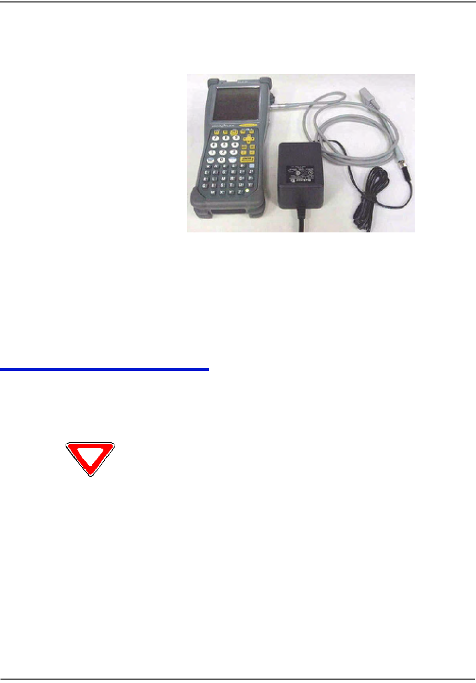
3Afterdatahasbeenuploaded,plugHandheldintochargingcable.
Figure D.2 Handheld DAP charging
POWER REQUIREMENTS
Neverallowthebatterytodiecompletely.Althoughtheroutedatasavestothe
flashmemorycard,thereisnoEPROMmemoryintheHandheld.Youwillhave
toreloadthecodeandre‐calibratethebattery.
Rebooting
TherearethreewaystoreboottheHandheld:
1PresstheF1,9,and0simultaneouslyforapproximatelyfiveseconds.
2Pressthefollowingkeysblue,CTL,ALT,blue,DEL.
3Exittheapplication(FromtheFunctionsscreenselectDock,donotplacein
cradleorpluginasrequested.PresstheshiftkeyfollowedbyF5).Type“C:”
thenpressENTER.Type“reset”thenpressENTER.
Do not remove the battery. The batteries are not made to be replaced as with the other
Handheld’s.

båÇ=çÑ=a~ó=e~åÇÜÉäÇ=fåëíêìÅíáçåë
`ÉääåÉí=d~ë=jçÇìäÉ=~åÇ=jÉíÉê=fåëí~ää~íáçå=dìáÇÉ aJP
HOW TO CHANGE THE HANDHELD ID
OccasionallytheHandheldIDmaybeenteredincorrectlyorthewrongHandheld
IDmaybeinaHandheldbecauseofamemorycardexchange.Thissectiontells
howtochangetheHandheldIDtothecorrectnumber.
1PlacetheHandheldinthecradleanddockit.
2OpenupthemostrecentversionofHandheldEdit.
3Select“Communication”then“TransferFiles”fromthemenuonHandheld
Edit.
4Ontherightsideofthepopupwindow,doubleclickonthe[CELLNET]
folder.
5SelectUnitinfo.datanddeleteit.Select“Yes”toverifythatyouwanttodelete
thefile.
6Select“OK”onthepopupwindowandcloseHandheldEdit.
7T
heHandheldwillthenpromptyoutoenterthelast4digitsoftheserial
numberonthebackoftheHandheld.
8BeforeusingtheHandheld,makesuretheproperrouteinformationisloaded
intotheHandheld.
KNOWN COMMON PROBLEMS
•IftheHandheldgetsjarred,thememorycardmaybecomedislodgedslightly.
Thismakesitlooklikeallofthedatahasbeenlost‐butitisstillthere.
UnscrewthetwoscrewsatthetopoftheHandheldbelowtheInfra‐red
scanner.Re‐seatthecardandre‐tightenthecover.Youmayneedtore‐boot
theHandheld.
•Ifthebluekeyandthenoneofthearrowkeysispushed,partofthescreen
seemstodisappear.Thescreenwasdesignedtoholdmoredata.Bluekey+
arrowishowyoushiftthescreentoviewthatdata.Pushthebluebuttonand
thearrowkeyintheoppositedirectionofthescreenshift.

Notes:
aJQ `ÉääåÉí=d~ë=jçÇìäÉ=~åÇ=jÉíÉê=fåëí~ää~íáçå=dìáÇÉ
båÇ=çÑ=a~ó=e~åÇÜÉäÇ=fåëíêìÅíáçåë
`ÉääåÉí=d~ë=jçÇìäÉ=~åÇ=jÉíÉê=fåëí~ää~íáçå=dìáÇÉ bJN
APPENDIX E DIFFICULT/NON-COMPATIBLE COMMERCIAL RETROFITS
ThisAppendixprovidesdetailedinstructionsoninstallingcommercialgas
modulesindifficultsettings,aswellasnon‐compatiblemoduleinstallations.
.
INDEX BASE PLATES WITH INTEGRAL SEAL CAPS
1Metersencounteredwiththeindexbaseplate(FigureE.1)requirethebase
platereplacedwithonethatdoesnothaveintegral“towers”.TheAmerican
MeterpartnumberforaBasePlatewithnotowersforDiaphragmmetersis
48828P038.Refertowww.americanmeter.comformoreinformation.
Figure E.1 Index Base Plate
aáÑÑáÅìäíLkçåJÅçãé~íáÄäÉ=`çããÉêÅá~ä=oÉíêçÑáíë
bJO `ÉääåÉí=d~ë=jçÇìäÉ=~åÇ=jÉíÉê=fåëí~ää~íáçå=dìáÇÉ
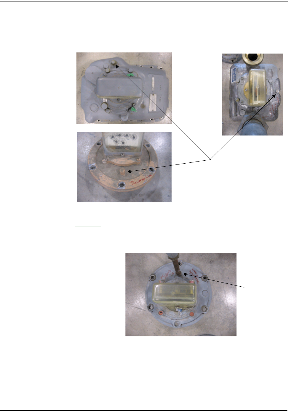
Pressure Tabs
MeterswithPressuretabsonthesurfaceneartheIndexmustberetrofittedin
suchawaythataccesstothepressuretapisnotcomprised.
Figure E.2 Meters with Pressure Tabs
FigureE.2indicatesthelocationsofthepressuretapplugsthatwillbefoundon
largemeters.FigureE.3showsameterwithaninstalledpressurefitting,a“Pete’s
Plug”.Themoduleinstallationmustnotinterferewiththemeterinstallation.
Figure E.3 Pressure Adapter
mêÉëëìêÉ=q~é=äçÅ~íáçå=mäìÖ=ãìëí=
ÄÉ=êÉãçîÉÇ=~åÇ=éêÉëëìêÉ=ëÉåëçê=
áåëí~ääÉÇK
mêÉëëìêÉ=~Ç~éíÉê
aáÑÑáÅìäíLkçåJÅçãé~íáÄäÉ=`çããÉêÅá~ä=oÉíêçÑáíë
`ÉääåÉí=d~ë=jçÇìäÉ=~åÇ=jÉíÉê=fåëí~ää~íáçå=dìáÇÉ bJP
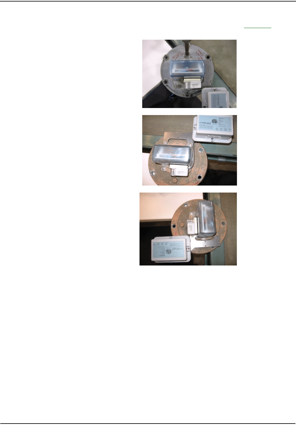
Forallofthesemetersthetransmitterportionofthemoduleneedstobemounted
sothataccessisstillavailabletothepressuretap,asshowninFigureE.4.
Figure E.4 Mounting Module’s Transmitter
aáÑÑáÅìäíLkçåJÅçãé~íáÄäÉ=`çããÉêÅá~ä=oÉíêçÑáíë
bJQ `ÉääåÉí=d~ë=jçÇìäÉ=~åÇ=jÉíÉê=fåëí~ää~íáçå=dìáÇÉ
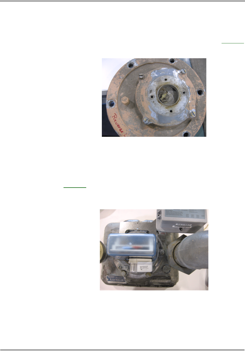
Reverse Loop Installations
Somemeterswillbeinstalledwiththepipingreversedfromthepreferred
orientation.Inthesecasestheindexisreversedtofacethebackofthemeter.Itis
extremelyimportantinthesecasesthattheBasePlatebemountedsuchthatthe
indexdrivefromthemeterbecenteredintheholeintheBaseplate.SeeFigureE.5
foranexampleoftheinsertbaseplatemountedbackwards.
Figure E.5 Plate Mounted Backwards
IfthisisencountereditcanbecorrectedbyrotatingtheIndexBasePlate180
degrees.
Large Pipe Fittings
FigureE.6showsameterthatdoesnothaveadequateclearancebetweenthePipe
fittingnutsandthemoduletransmitter.Ininstallationssuchasthis,themodule
bracketmustberemovedbeforethemetercanberemovedfromservice.
Figure E.6 Pipe Clearance
aáÑÑáÅìäíLkçåJÅçãé~íáÄäÉ=`çããÉêÅá~ä=oÉíêçÑáíë
`ÉääåÉí=d~ë=jçÇìäÉ=~åÇ=jÉíÉê=fåëí~ää~íáçå=dìáÇÉ bJR
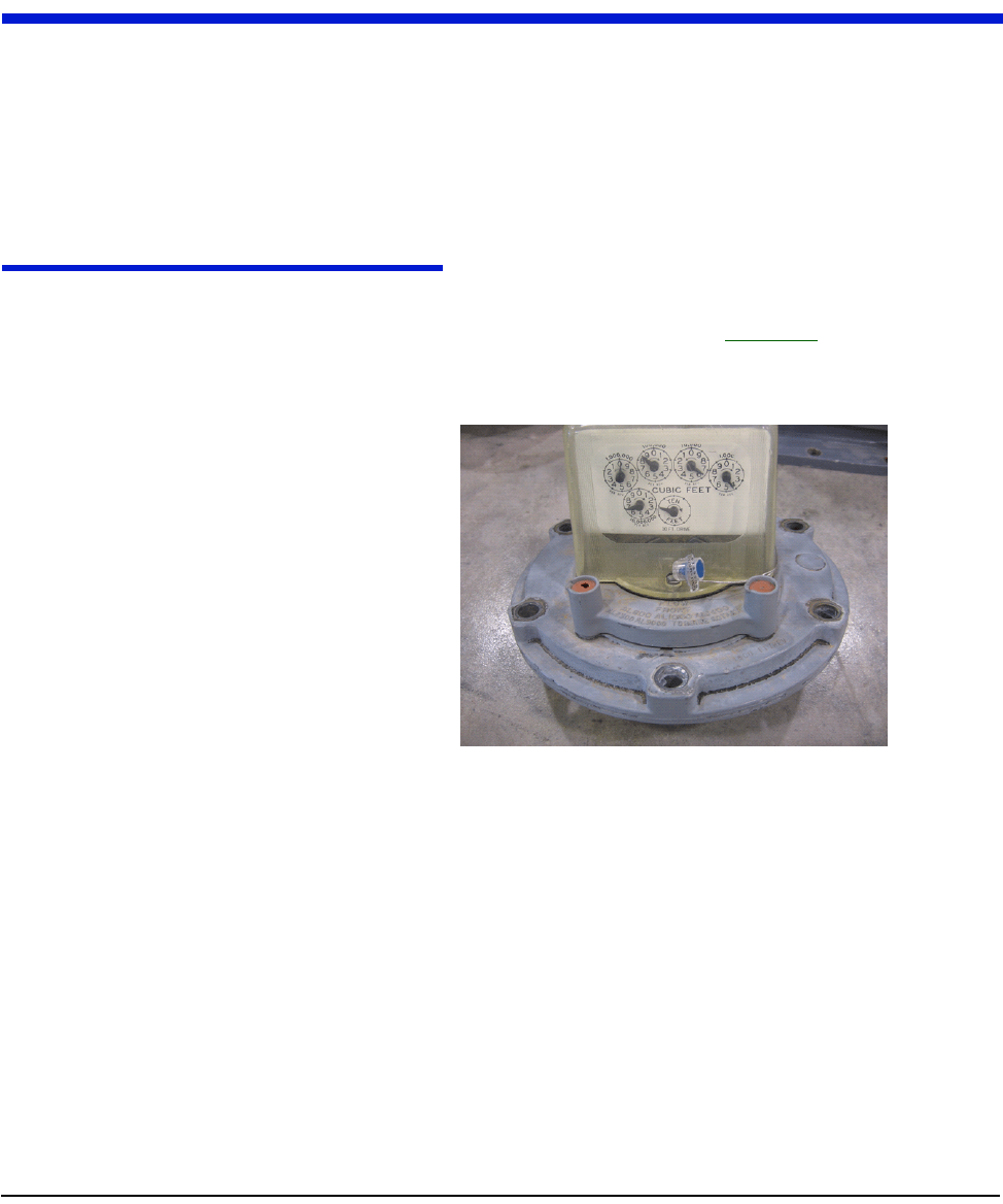
Protective Index Enclosures
CellnetCommercialGasModulesarenotcompatiblewithmetersthatuse
protectiveenclosuresovertheindexes(FigureE.7).
Figure E.7 Protective Index Enclosures

Notes:
bJS `ÉääåÉí=d~ë=jçÇìäÉ=~åÇ=jÉíÉê=fåëí~ää~íáçå=dìáÇÉ
aáÑÑáÅìäíLkçåJÅçãé~íáÄäÉ=`çããÉêÅá~ä=oÉíêçÑáíë
ríáäákÉí=NJt~ó=mìäëÉ=oÉÅçêÇÉê=Ñçê=d~ë=^ééäáÅ~íáçåë cJN
APPENDIX F CPR INFORMATION
UsethisprocesstocrimpwiresfortheCellnetPulseRecorder.
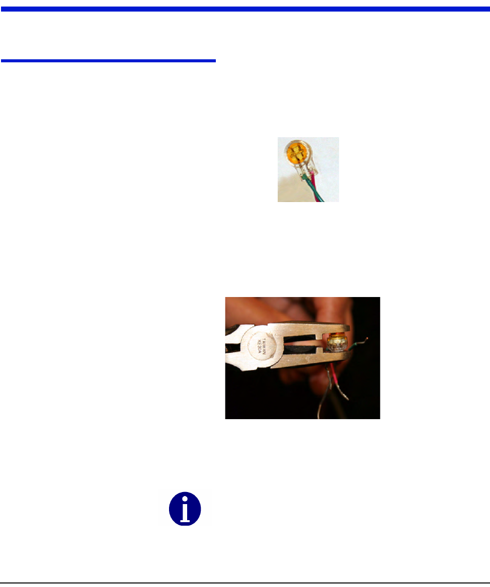
CRIMPING WIRES
1PushthewirestobeconnectedasfaraspossibleintotheScotchlokconnector.
Figure F.1 Wires Pushed into Scotchlok Connector
2PlacetheScotchlokconnector(withwires)intothejawsofthecrimpingtool.
Figure F.2 ScotchLok Connector in Crimping Tool Jaws
Alwaysuse3MParallelJawCrimpingTool3MModelE‐
9Yorequivalent.
`mo=fåÑçêã~íáçå
cJO ríáäákÉí=NJt~ó=mìäëÉ=oÉÅçêÇÉê=Ñçê=d~ë=^ééäáÅ~íáçåë
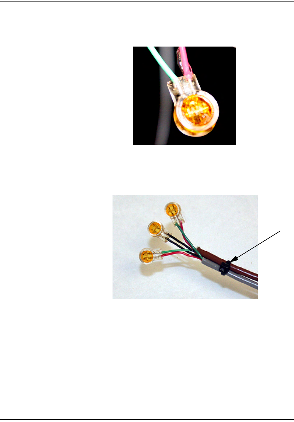
3CrimptheScotchlokconnectorbysqueezingthehandlesuntilitdischarges
gel.Continuetoapplypressureforthreeseconds.
Figure F.3 Crimped Scotchloks Discharge Gel
4Placetwoplasticcabletiesonwiresandtightensecurelyforstrainrelief.
Removeexcesscabletiewithwirecutters.
Figure F.4 Placing Plastic Ties on Cables
mä~ëíáÅ=qáÉë
`mo=fåÑçêã~íáçå
ríáäákÉí=NJt~ó=mìäëÉ=oÉÅçêÇÉê=Ñçê=d~ë=^ééäáÅ~íáçåë cJP
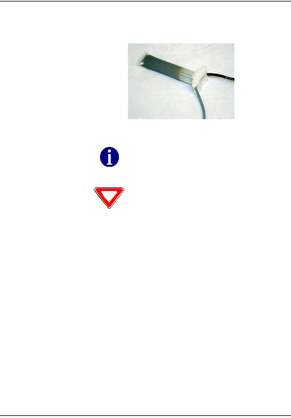
5ForspliceconnectionsoutsidetheCPRenclosure,inserttheentiresplice
assemblyintothesilicone‐filledspliceenclosure.Closethecoverwithleads
exitingalternatesides.
Figure F.5 Inserting Splice Assembly into Silicone-filled Splice Enclosure
The 3M Gel splice connector is NOT reusable. Replace the splice if
necessary.
Cellnet strongly recommends a splice enclosure for all CPR
applications.


Reader’s Comment Form
CellnetGasMeterandModuleInstallationGuide(CO‐0089‐GB‐07.07)
Pleaseusethisformonlytoidentifypublicationerrorsortorequestchangesinpublications.Your
commentsassistusinimprovingourpublications.Directanyrequestsforadditionalpublications,
technicalquestionsaboutsystems,changesinsupport,andsoon,toyourCellnetsalesrepresentative.You
mustusethisformtocommunicateyourcommentsaboutthispublication,itsorganization,orsubject
matter,withtheunderstandingthatwemayuseordistributewhateverinformationyousupplyinany
waywebelieveappropriatewithoutincurringanyobligationtoyou.
Youcansendcommentsviaemail,conventionalmail,orfax.
Ifyourcommentdoesnotneedareply(forexample,pointingoutatypingerror),checkthisboxand
donotincludeyournameandaddressbelow.Ifyourcommentisapplicable,wewillincludeitinthe
nextrevisionofthemanual.
Ifyouwouldlikeareply,checkthisbox.Besuretoprintyournameandaddressbelow.
(Pleaseprint.)
To send your comments via... Use this contact information...
bã~áä ÅìëíçãÉêëìééçêí]ÅÉääåÉíKÅçã
`çåîÉåíáçå~ä=ã~áä `ÉääåÉíI=PMMMM=jáää=`êÉÉâ=^îÉKI=pìáíÉ=NMMI=^äéÜ~êÉíí~I=d^=PMMOO
c~ñ ESTUF=ORUJNRRM
Page Comments
Date CompanyName
YourName MailingAddress
PhoneNo.
Email

cçäÇ=eÉêÉ
cçäÇ=eÉêÉ
Cellnet
Attn.:MarketingCommunications
30000MillCreekAve.
Suite100
Alpharetta,GA30022