Landis Gyr Technology EG0R3S2 GAS METER TRANSMITTER MODULE User Manual USERS MANUAL 2
Landis+Gyr Technology, Inc. GAS METER TRANSMITTER MODULE USERS MANUAL 2
Contents
- 1. USERS MANUAL 2
- 2. USERS MANUAL 1
- 3. USERS MANUAL 3
- 4. USERS MANUAL 4
USERS MANUAL 2

5015 B.U. Bowman Drive Buford, GA 30518 USA Voice: 770-831-8048 Fax: 770-831-8598
Certification Exhibit
FCC ID: R7PEG0R3S2
IC: 5294A-EG0R3S2
FCC Rule Part: 15.247
IC Radio Standards Specification: RSS-210
ACS Report Number: 07-0243-15C
Manufacturer: Cellnet Technology, Inc.
Model(s): 25-1075, 25-1080, 25-1081
Manual
(Part 2 of 4)
oÉëáÇÉåíá~ä=jÉíÉê=jçÇìäÉ=oÉíêçÑáí
RJO `ÉääåÉí=d~ë=jçÇìäÉ=~åÇ=jÉíÉê=fåëí~ää~íáçå=dìáÇÉ
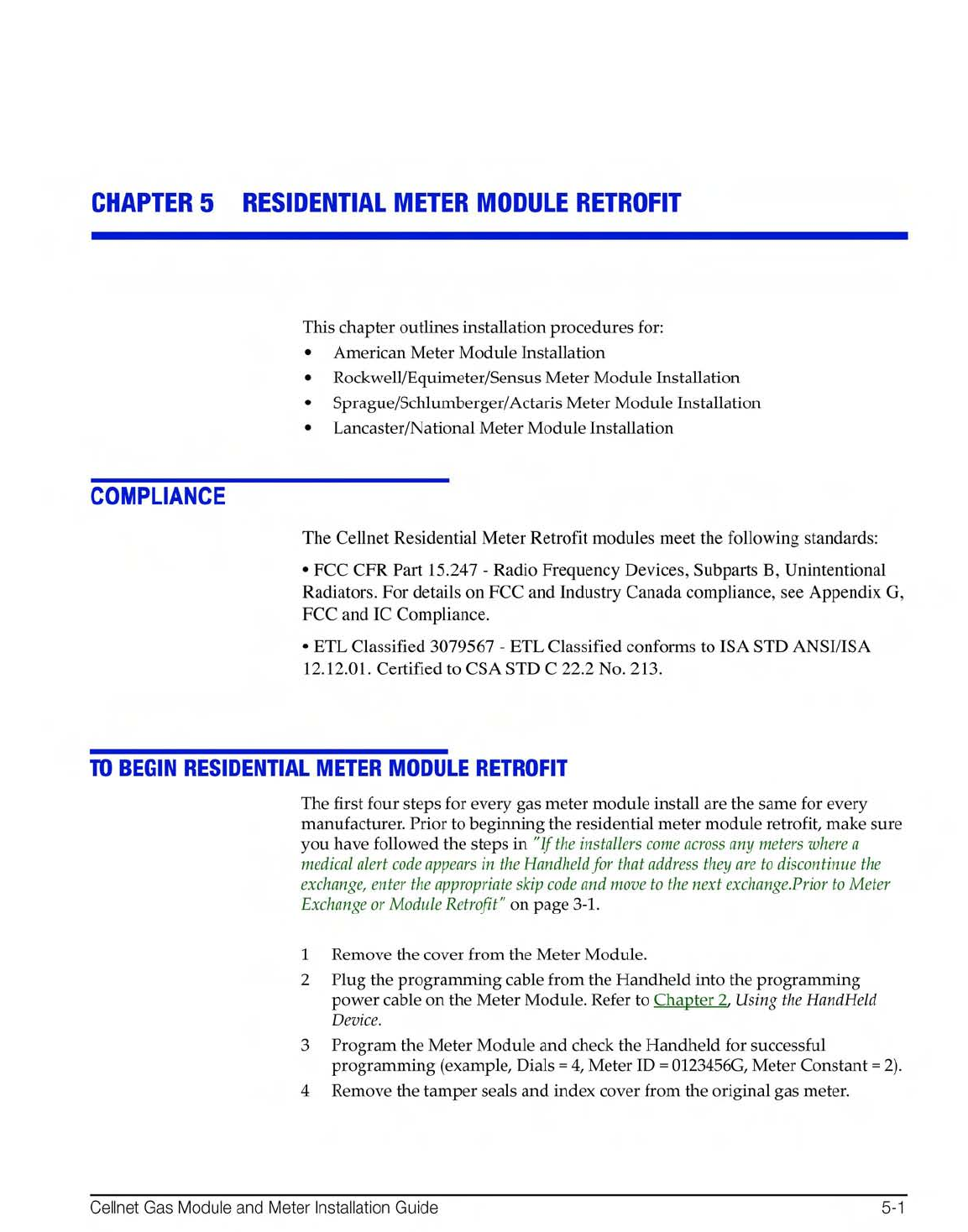
American Installation
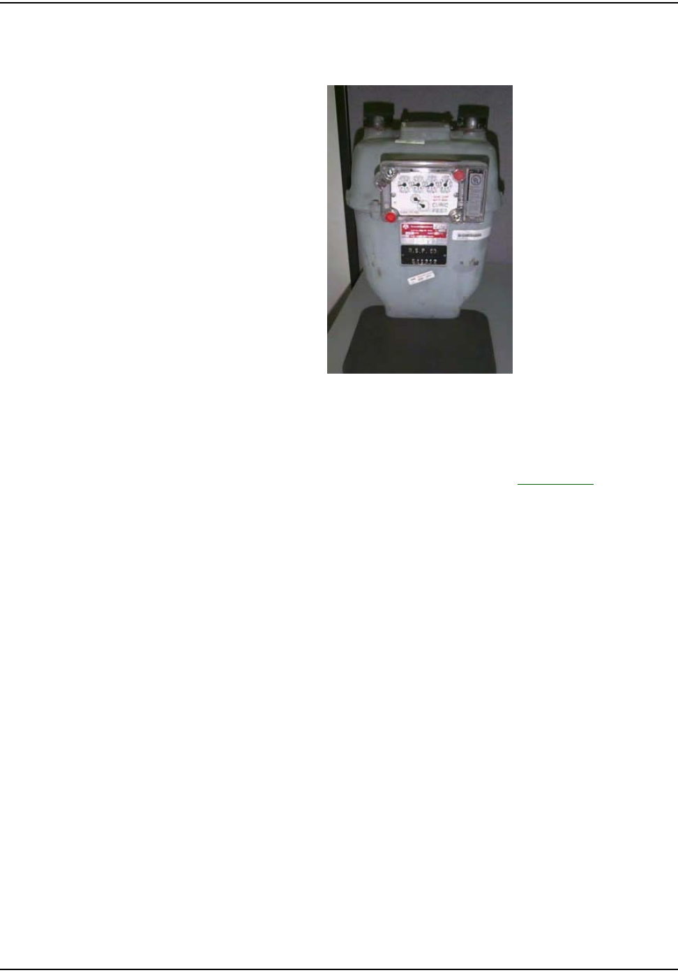
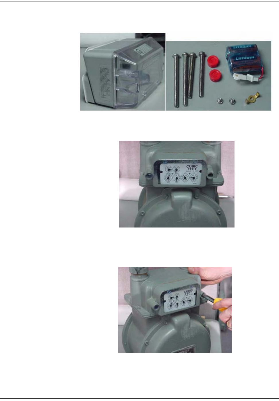
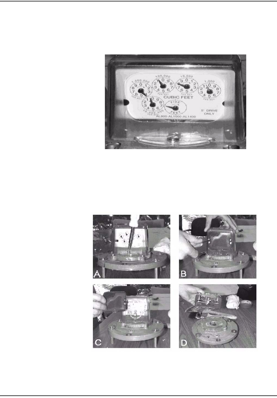
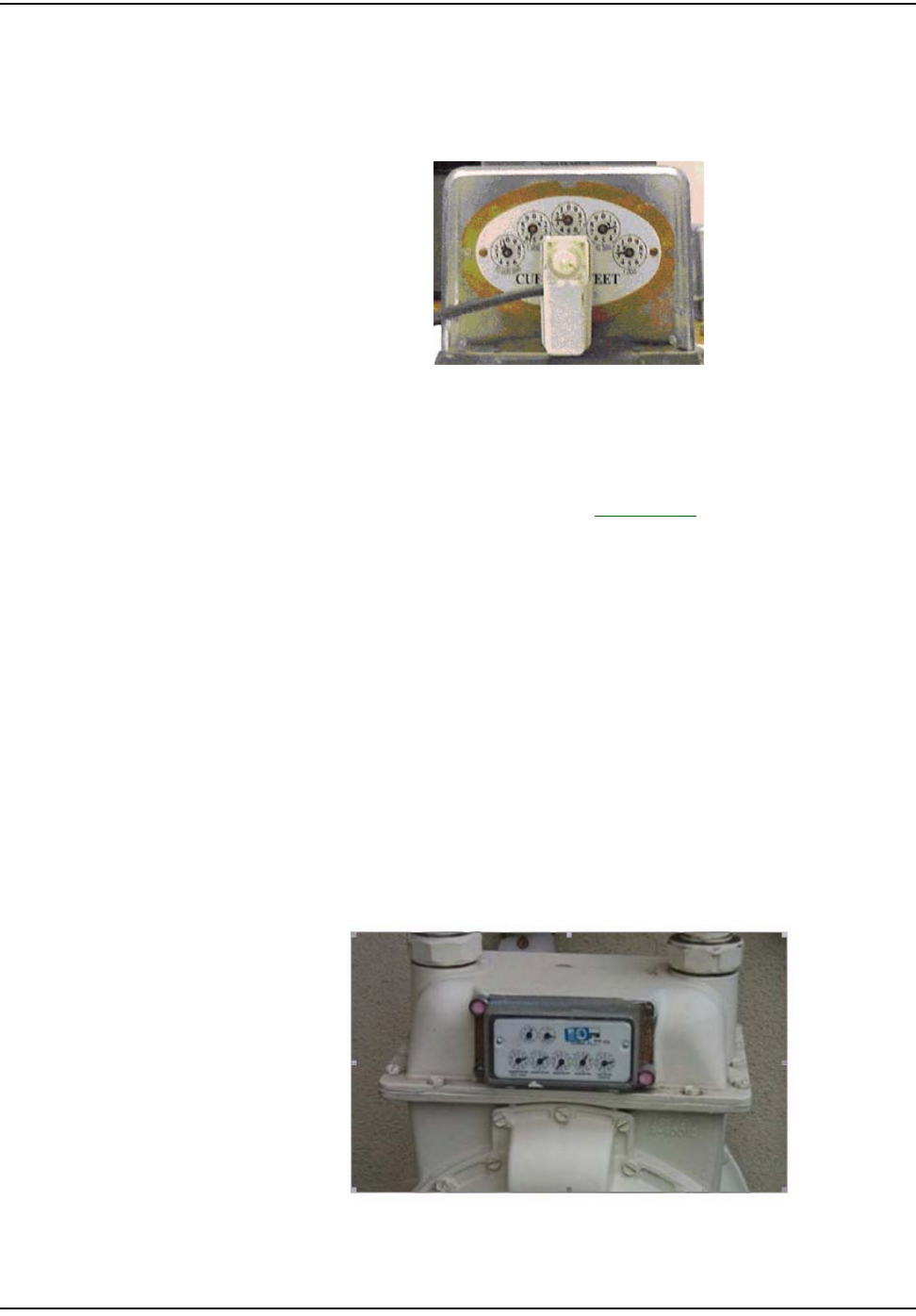
Figure 5.1 American: Meter Module before installation
1Followsteps1‐4inʺToBeginResidentialMeterModuleRetrofitʺonpage 5‐1.
Figure 5.2 American: meter with index and index cover
oÉëáÇÉåíá~ä=jÉíÉê=jçÇìäÉ=oÉíêçÑáí
`ÉääåÉí=d~ë=jçÇìäÉ=~åÇ=jÉíÉê=fåëí~ää~íáçå=dìáÇÉ RJP
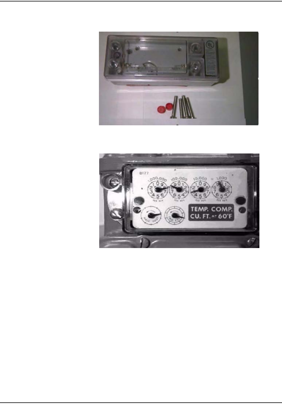
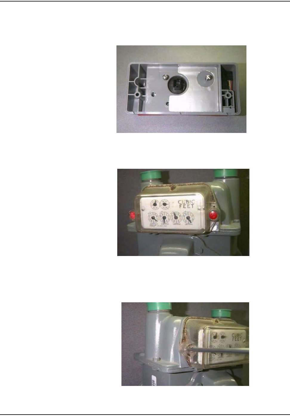
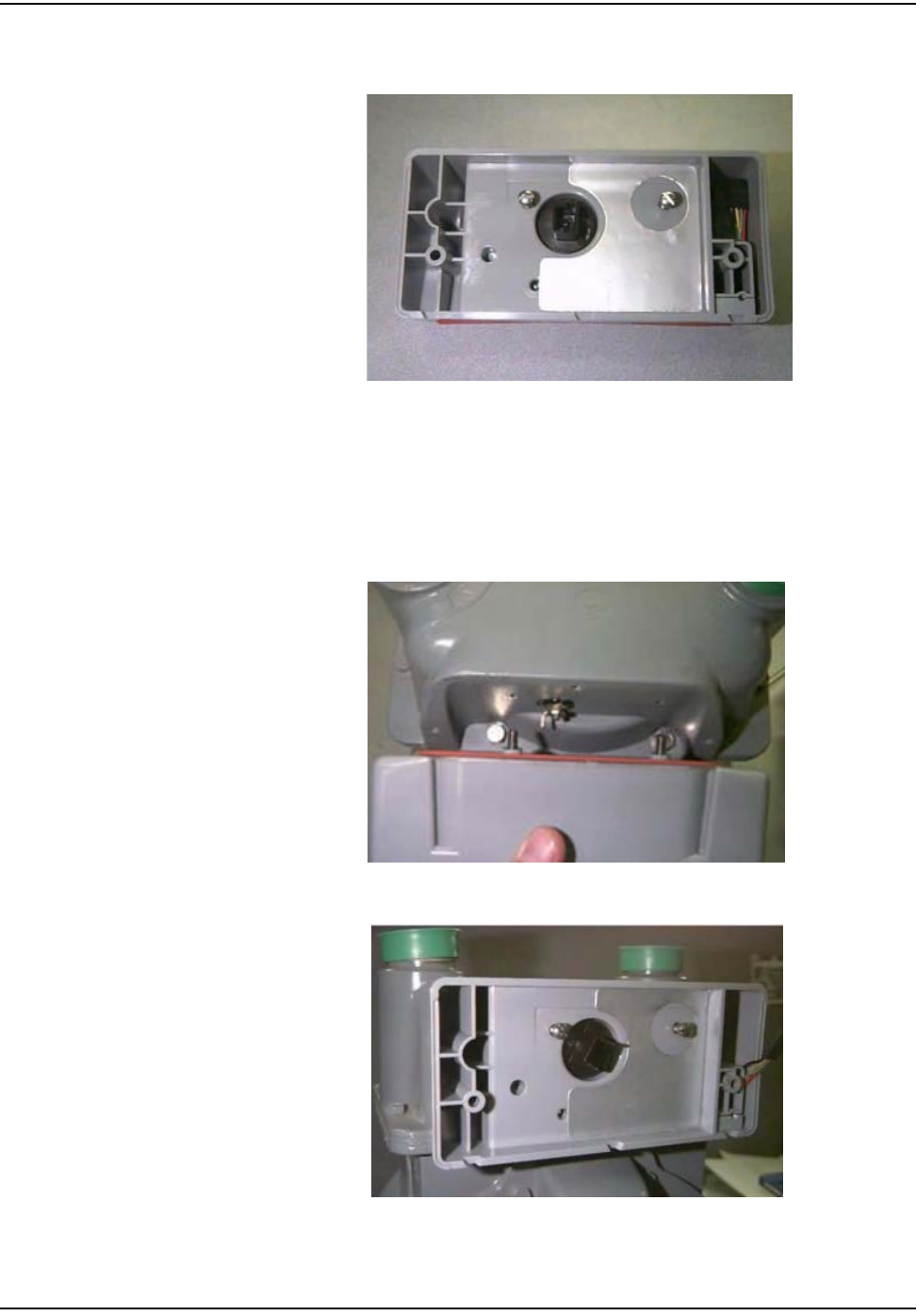
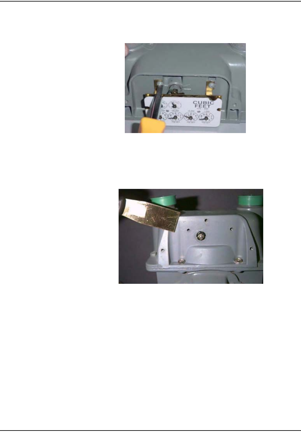
2Removetheindexdialsfromthegasmeter.Alsoremovealloftheoriginal
gasketmaterial.Replacetheindexifitisdamagedorifthegearsare
discolored.
WHENREPLACINGANINDEXYOUMUSTENTERTHEMETERREAD
INTOTHEHANDHELDANDINTHECOMMENTSECTIONWRITE
“INDEXEXCHANGED”.ForIndexvisualverificationandexchangeon
AmericanmetersseeAppendix B,VisualInspectionofIndexes.
Figure 5.3 American Removing the Index (one screw on each side)
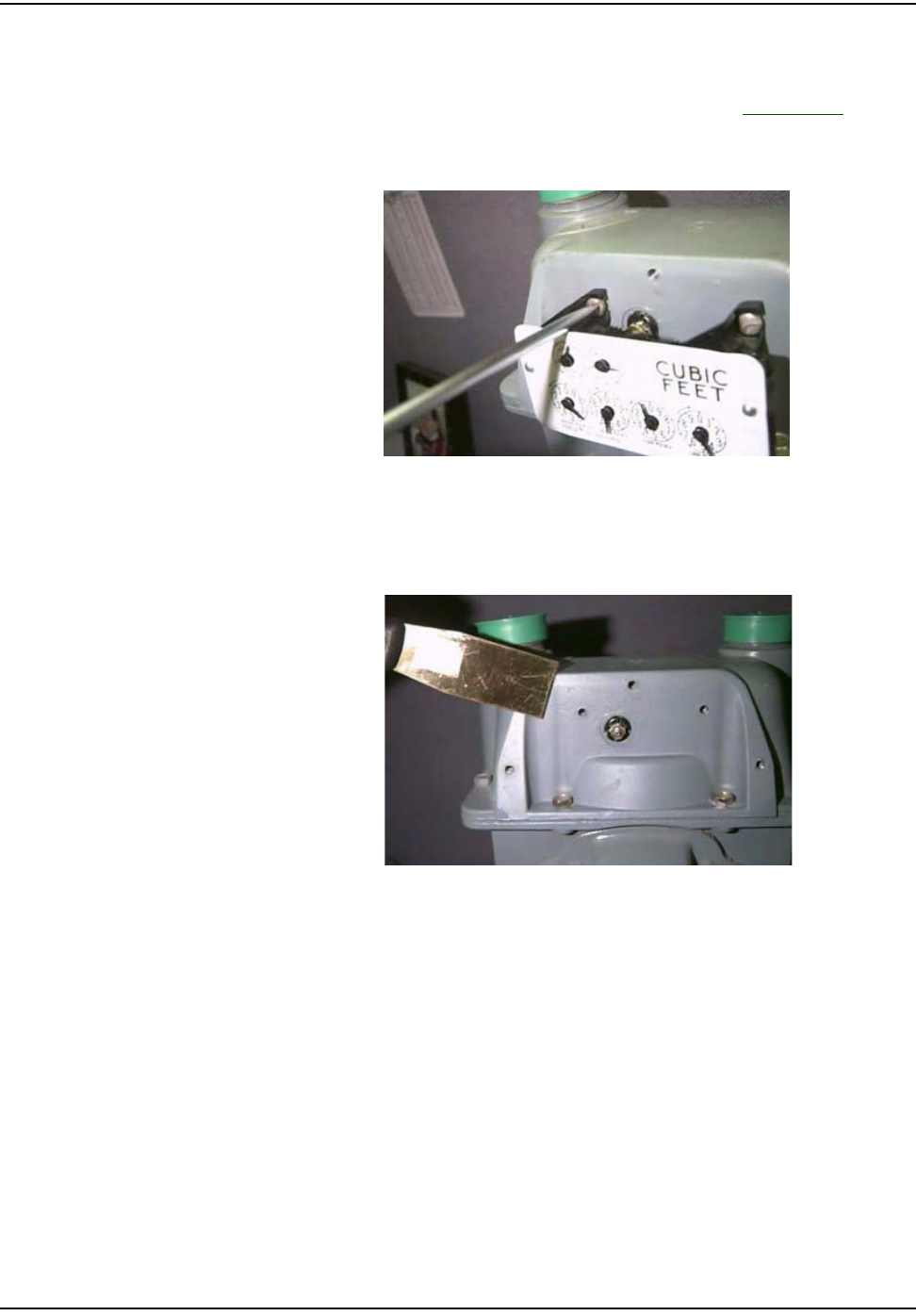
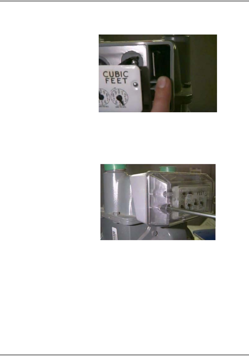
3Cleantheareabehindtheindexandcovergasketsurfaceonthemeterwitha
wirebrushandgasketscraper.
4Makesurethatthelocationofthedialsonthemeterisfreeofanydebristhat
mayhampermoduleinstallation.
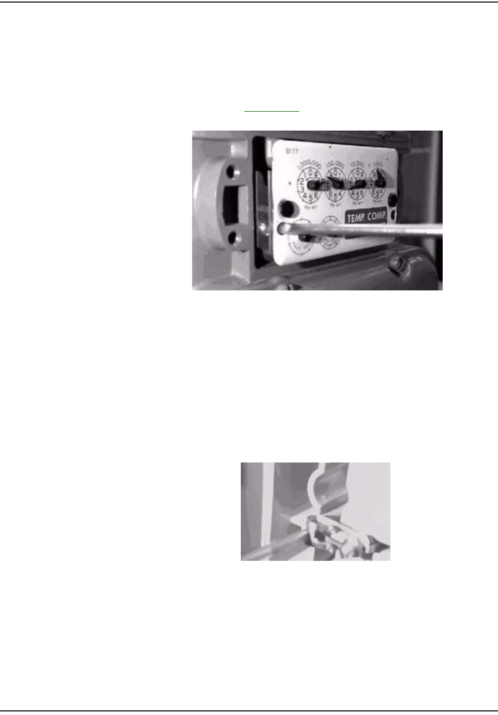
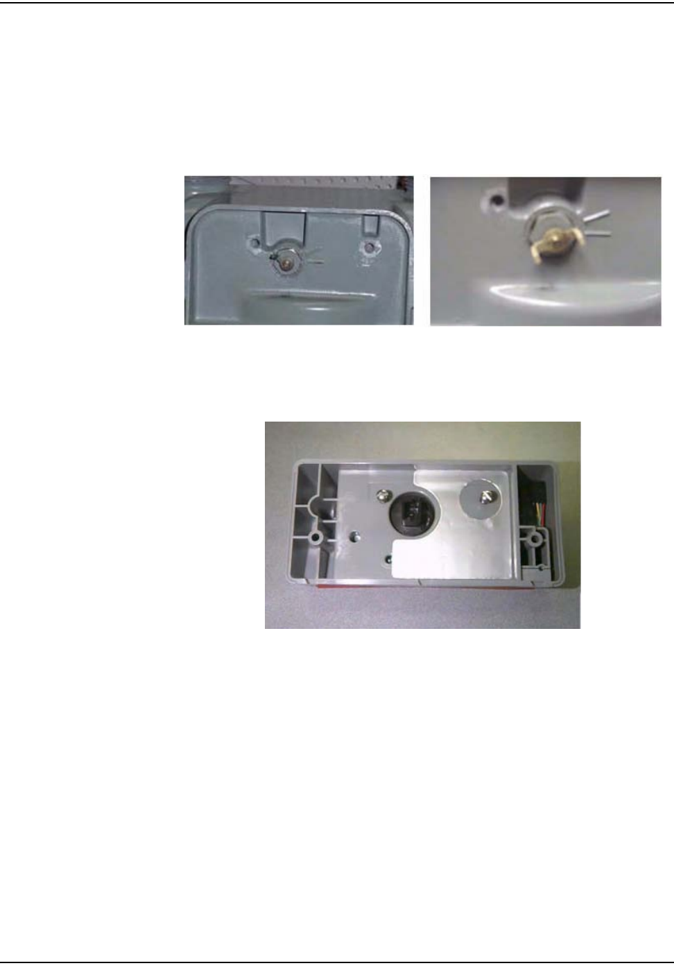
5Slidetheindexattachmentclipsouttothesidesbeforebeginningtoinstall
moduleonmeter.
Figure 5.4 American: Sliding the Index attachment clip out (one per side)
oÉëáÇÉåíá~ä=jÉíÉê=jçÇìäÉ=oÉíêçÑáí
RJQ `ÉääåÉí=d~ë=jçÇìäÉ=~åÇ=jÉíÉê=fåëí~ää~íáçå=dìáÇÉ
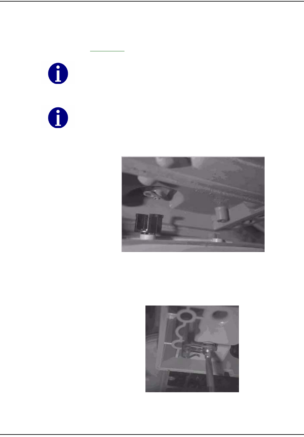
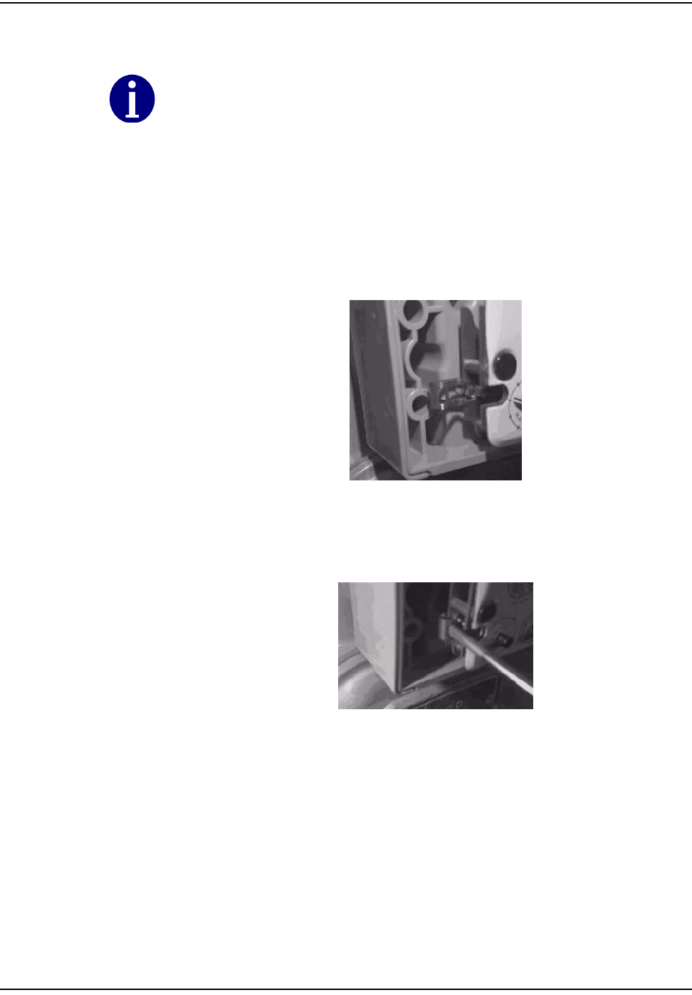
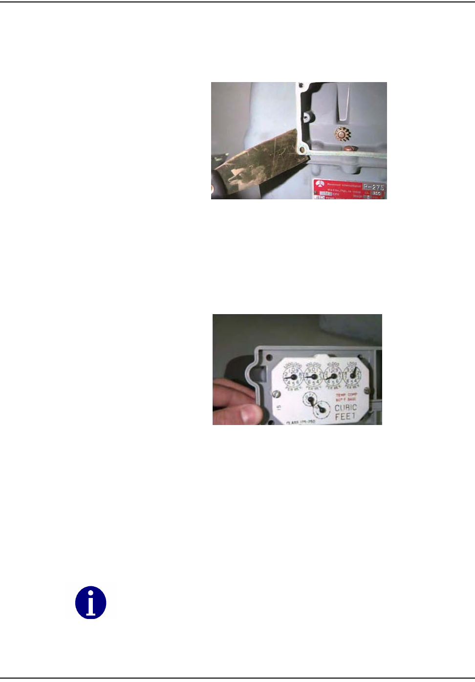
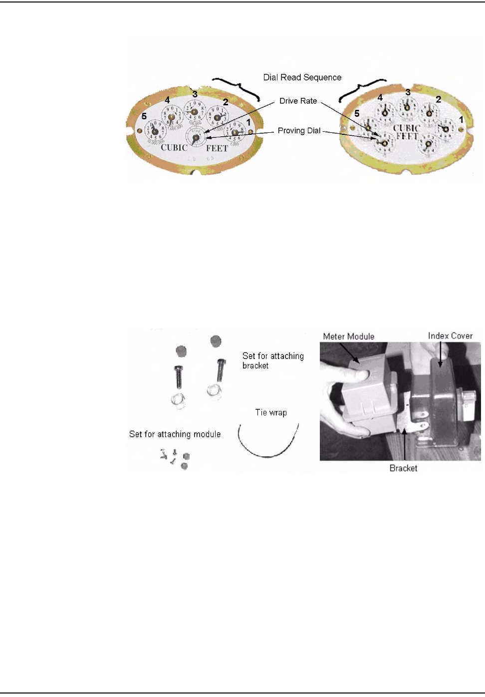
6AlignthemeterdrivedogwiththemodulewigglerandinstalltheMeter
Modulebasetothemeterbyscrewinginthetwocapturedstandoffscrews.
Thetorquerequirementforfasteningthescrewsis10inch‐pounds.For
modulesmanufacturedstartinginMay2005,forproperalignmentsee
Appendix A,AligningtheNewAmericanMeterDriveDog.
Figure 5.5 American: Aligning the drive dog
Figure 5.6 American: Attaching the Meter Module onto the meter by screwing in two stand-off
fasteners
Check the wiggler on the meter module for free movement. Wiggler should turn at least 10
degrees but no greater than a 1/4 turn. If it is binding, then disassemble and realign. This is
also known as the “wiggle” test.
Improper alignment or tightening of the standoff screws may result in module or meter
failure.
oÉëáÇÉåíá~ä=jÉíÉê=jçÇìäÉ=oÉíêçÑáí
`ÉääåÉí=d~ë=jçÇìäÉ=~åÇ=jÉíÉê=fåëí~ää~íáçå=dìáÇÉ RJR
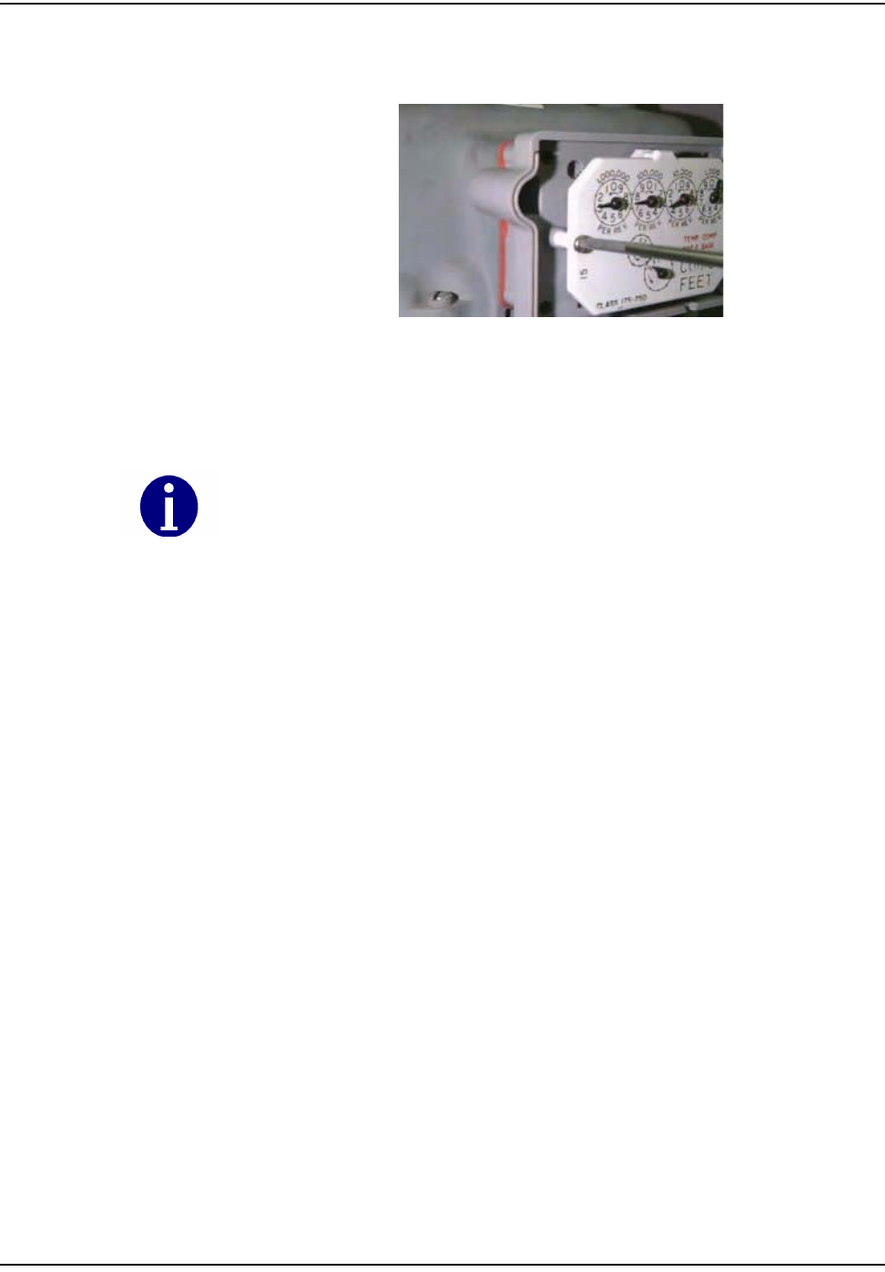
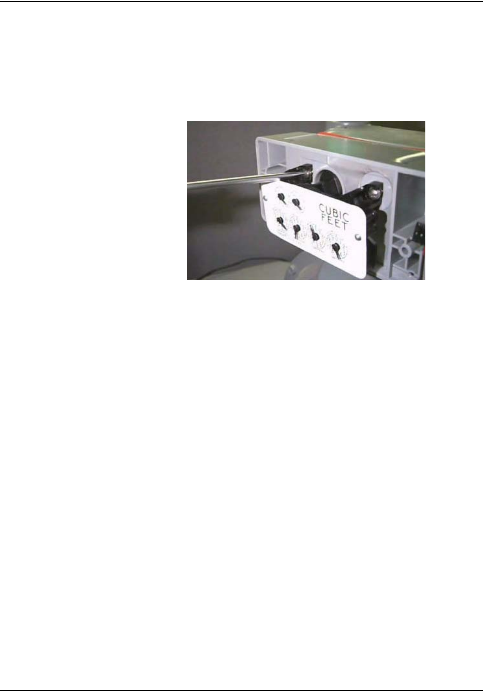
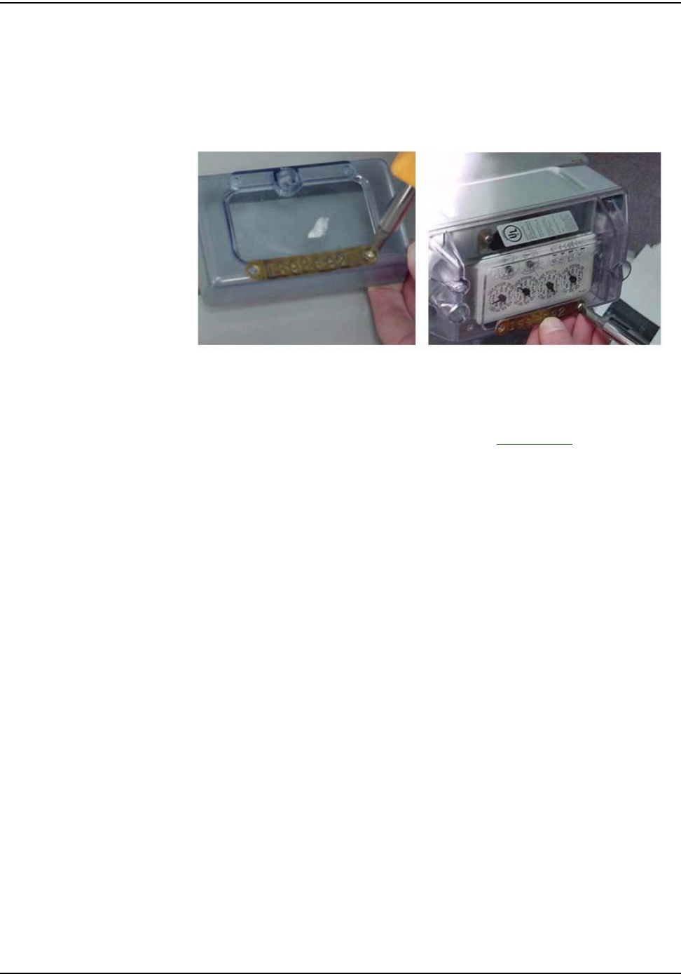
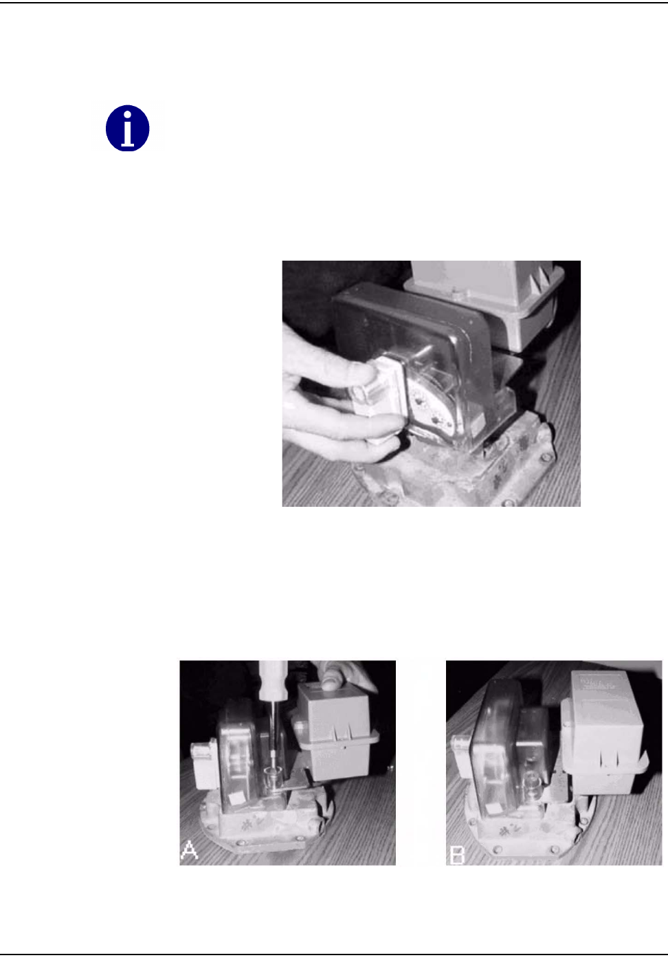
7 AttachtheindextotheMeterModulehousingwiththecapturedclipsonthe
standoffscrews.Besurethattheclipsareextendedfullytowardstheoutside
edgeofthemodulewhenyoufittheindextothemodule,andaligntheindex
dogoftheindextothemoduleʹswiggler.Pushthetwoclipstowardsthe
insideofthemoduletosecuretheindex.Aftertheindexisinstalled,the
installermustturntheprovingdialontheindextoensuretheindexis
properlyengagedwiththemodule.
Figure 5.7 American: Installing Index on standoff screws
Figure 5.8 American: Sliding the Index clip in
Use torque screwdriver set at 10 inch-pounds to install the two captured standoff screws
for all module installations.
oÉëáÇÉåíá~ä=jÉíÉê=jçÇìäÉ=oÉíêçÑáí
RJS `ÉääåÉí=d~ë=jçÇìäÉ=~åÇ=jÉíÉê=fåëí~ää~íáçå=dìáÇÉ
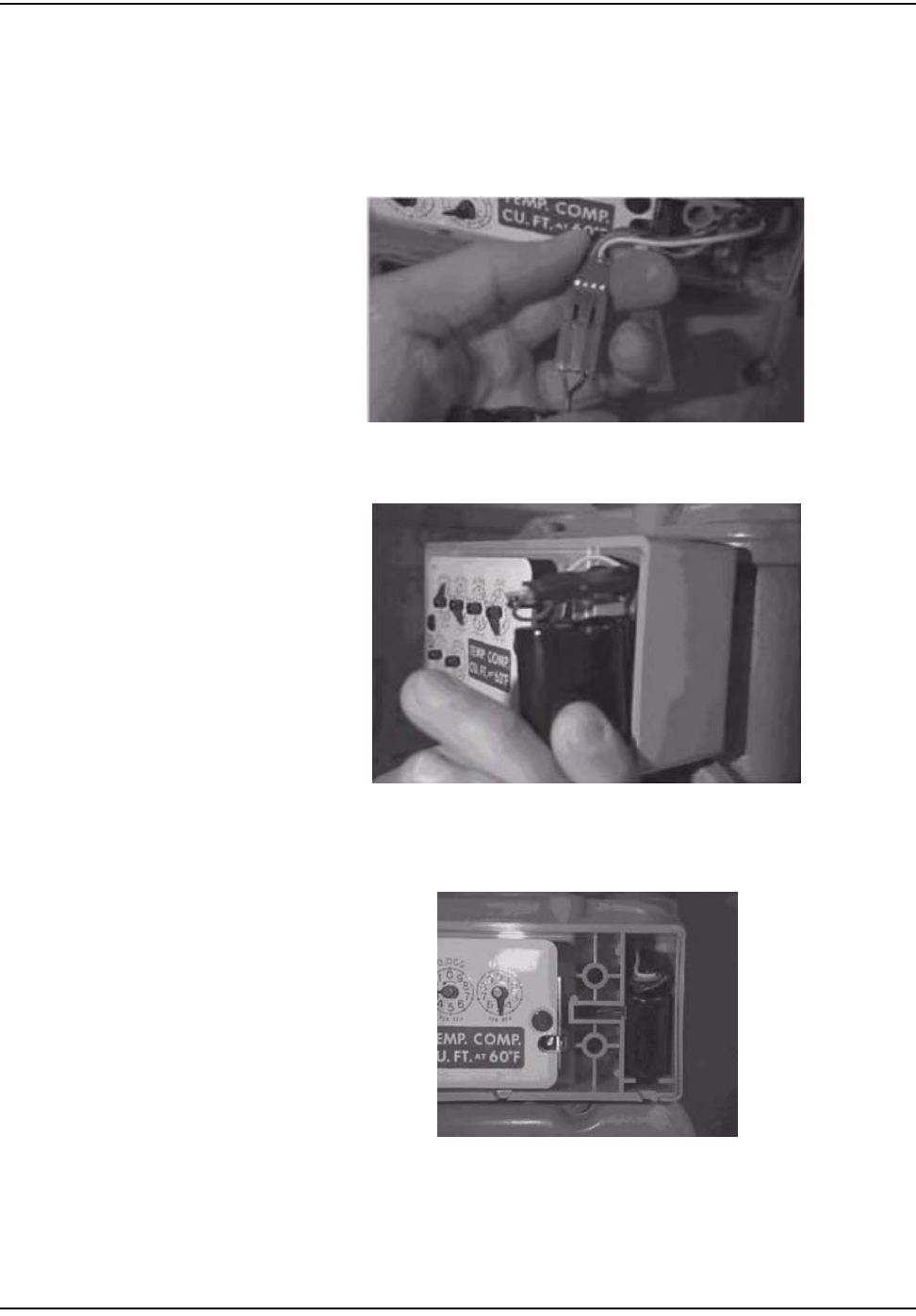
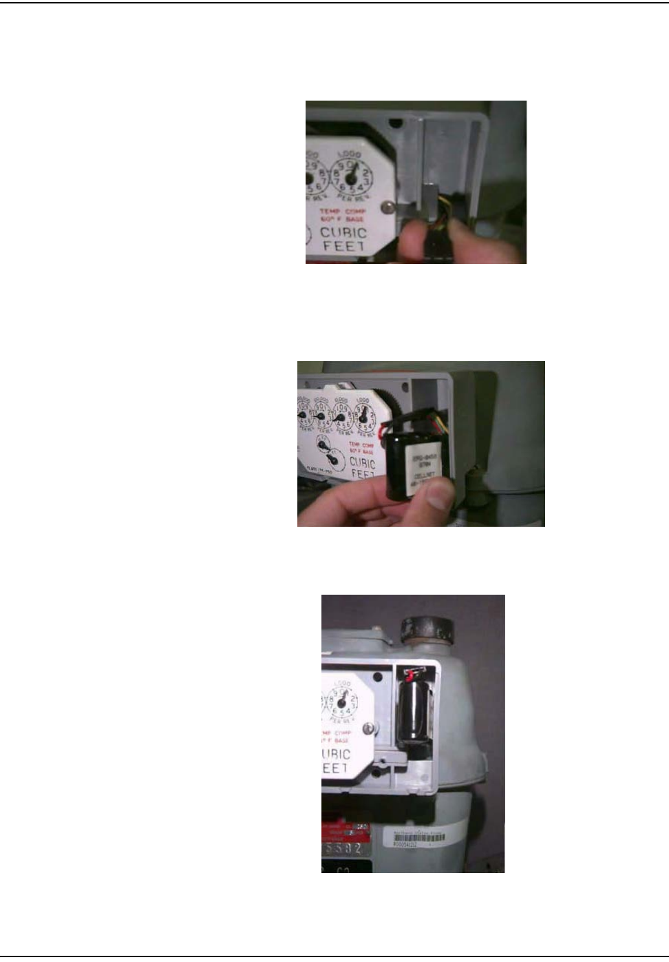
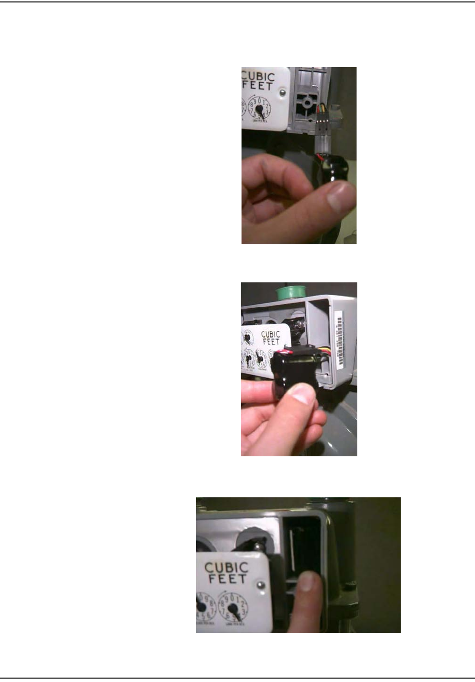
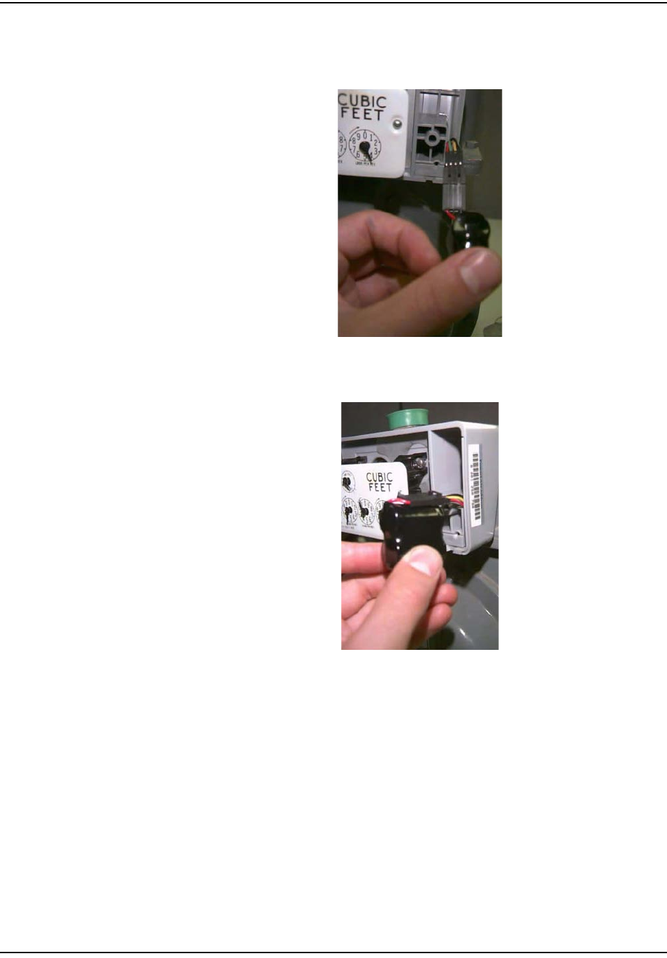
8Plugthebatteryintotheprogrammingportpowercableandplaceitinthe
batterycompartmentwiththebatterywiresontop.
Figure 5.9 American: Connecting the battery
Figure 5.10 American: Installing the battery with the battery cable on top
Figure 5.11 American: Properly installed battery
oÉëáÇÉåíá~ä=jÉíÉê=jçÇìäÉ=oÉíêçÑáí
`ÉääåÉí=d~ë=jçÇìäÉ=~åÇ=jÉíÉê=fåëí~ää~íáçå=dìáÇÉ RJT
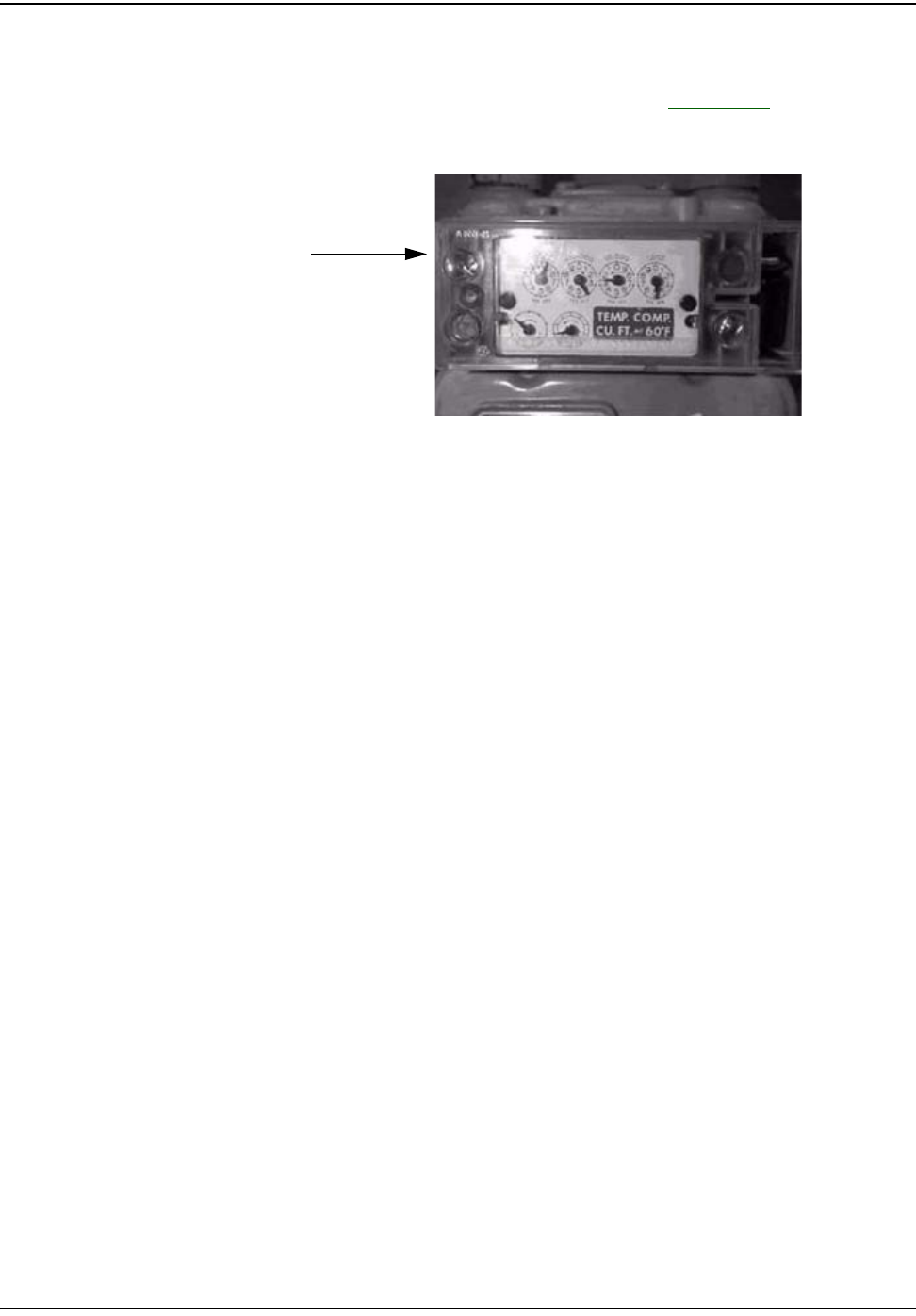
9UtilizetheRFBustertoverifymoduleistransmitting,holdtheRFBusterwith
magnetsidetothetopupperleftquadrantofthemoduleplasticcoverand
holdthebuttonuntil10beepsarereceived.SeeAppendix C,UsingtheRF
Busterformoreinformation.
Figure 5.12 American: Meter module with cover and tamper seals installed
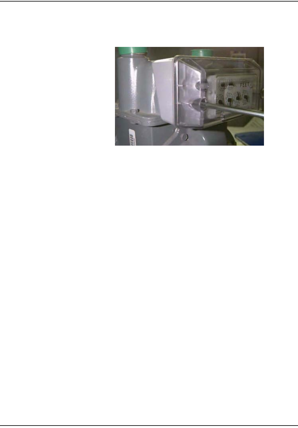
10 InstallthecoverontheMeterModulebase,usingthefourscrewsthatwere
provided.Tightenthescrewsuntilthecoversitssnug,thentightenan
additionalquarterturn.
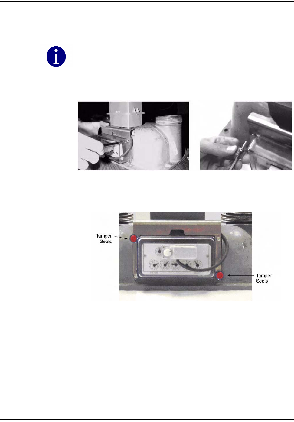
11 Installnewredtampersealsovertwodiagonalscrews(upperrightandlower
left,orupperleftandlowerright).
12 Cleanupanydebrisfromtheretrofitandinstallationprocesses,andleavea
doorhangertagwithanyappropriateinformationfilledin.Makesureto
alwaysleaveadoorhanger.
13 Attheendoftheday,theinstallerreturnstotheCrossDockforthecheck‐in
process.Theinstallershouldalsoturnininventoryofunused,defective,or
brokengasMeterModules.TheInstallermustcheckinallHandheldsissued.
Theinstallerisresponsibleforreconcilinganydiscrepanciesinchangeddata
beforethecheck‐inprocesscanbecompleted.MetersModuleswillnotbe
checkedouttoaninstallerwhohasnotcompletedthepreviousdayʹscheck‐in
process.
Magnetlocation
for“busting”
oÉëáÇÉåíá~ä=jÉíÉê=jçÇìäÉ=oÉíêçÑáí
RJU `ÉääåÉí=d~ë=jçÇìäÉ=~åÇ=jÉíÉê=fåëí~ää~íáçå=dìáÇÉ
Rockwell/Equimeter/Sensus Meter Module Installation
Figure 5.13 Rockwell/Equimeter/Sensus: meter module before installation
Figure 5.14 Rockwell/Equimeter/Sensus: meter
1Followsteps1‐4inʺToBeginResidentialMeterModuleRetrofitʺonpage 5‐1.
Figure 5.15 Rockwell/Equimeter/Sensus: Meter with tamper seals and index cover removed
oÉëáÇÉåíá~ä=jÉíÉê=jçÇìäÉ=oÉíêçÑáí
`ÉääåÉí=d~ë=jçÇìäÉ=~åÇ=jÉíÉê=fåëí~ää~íáçå=dìáÇÉ RJV
2Removetheindexandalloftheoriginalgasketmaterial.Cleanthearea
behindtheindexonthemeterwithawirebrushandgasketscraperto
removealldebris.
Figure 5.16 Rockwell/Equimeter/Sensus: Removal of index cover gasket
3InsertthetwoscrewsthroughtheindexandthroughtheMeterModulebase.
Ensurethatthemoduleʹswigglerandthemeterdrivedogoftheindexare
properlyaligned.
Figure 5.17 Rockwell/Equimeter/Sensus: Meter Module and index with screws in place ready for
assembly
4WhileholdingtheindexandMeterModulebasetogether,alignthemeter
drivedogwiththemodulewiggler.Thetorquerequirementforfasteningthe
screwsis4‐8inch‐pounds.RefertoʺRockwell/Equimeter/Sensus:Attachingthe
MeterModuleandindextothemeterʺonpage 5‐10.
Do not over tighten the standoff screws; if module wiggler and meter drive dog are not
aligned properly it may result in a meter failure.
Check the wiggler on the meter module for free movement. The wiggler should turn at
least 10 degrees, but no greater than 1/4 turn. If it is binding, then disassemble and
realign. This is also known as the "wiggle" test.
oÉëáÇÉåíá~ä=jÉíÉê=jçÇìäÉ=oÉíêçÑáí
RJNM `ÉääåÉí=d~ë=jçÇìäÉ=~åÇ=jÉíÉê=fåëí~ää~íáçå=dìáÇÉ
Figure 5.18 Rockwell/Equimeter/Sensus: Attaching the Meter Module and index to the meter
5Gentlywigglethetwo‐footprovingdialtomakesurethegearsaremeshed
properly.Thereshouldbenogreaterthan1/4turnplay.
All of the original gasket and all debris must be completely removed or it will result in a
module and meter failure.
oÉëáÇÉåíá~ä=jÉíÉê=jçÇìäÉ=oÉíêçÑáí
`ÉääåÉí=d~ë=jçÇìäÉ=~åÇ=jÉíÉê=fåëí~ää~íáçå=dìáÇÉ RJNN
6Plugthebatteryintotheprogrammingpowercableandplaceitinthebattery
compartmentwiththebatterywiresontop.
Figure 5.19 Rockwell/Equimeter/Sensus: Connecting the battery
Figure 5.20 Rockwell/Equimeter/Sensus: Correct battery orientation (connector on top)
Figure 5.21 Rockwell/Equimeter/Sensus: Battery properly installed
oÉëáÇÉåíá~ä=jÉíÉê=jçÇìäÉ=oÉíêçÑáí
RJNO `ÉääåÉí=d~ë=jçÇìäÉ=~åÇ=jÉíÉê=fåëí~ää~íáçå=dìáÇÉ
7UsethefourremainingscrewstoinstallthecovertotheMeterModulebase,
tighteningthescrewsuntilthecoversitssnug,thentightenanadditional
quarterturn.
Figure 5.22 Rockwell/Equimeter/Sensus: Installing the Meter Module cover
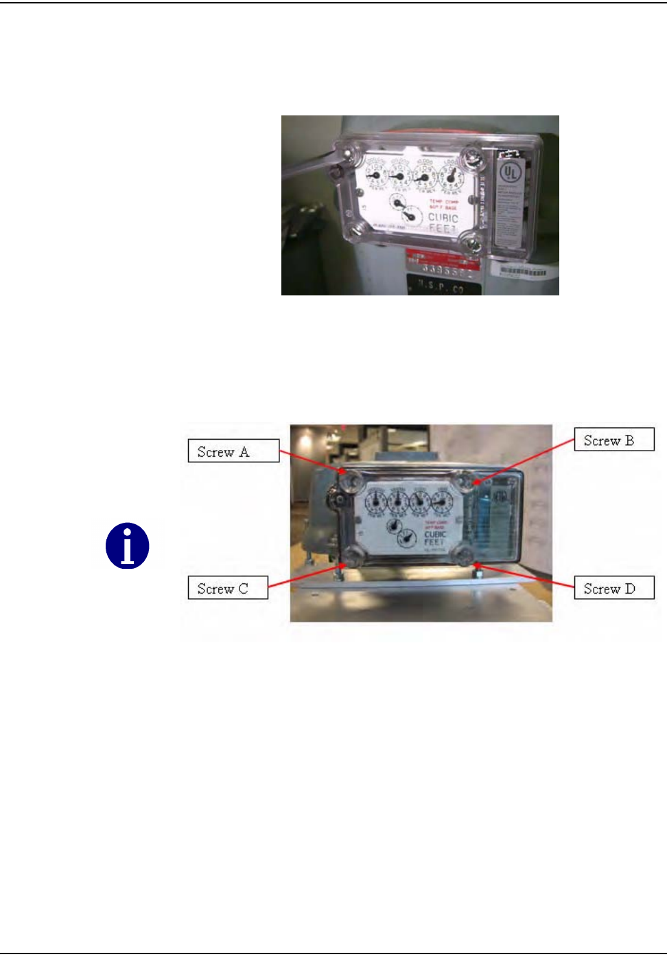
You can mount an Equimeter module to a Rockwell/Equimeter Residential Gas meter using
only two screws, as long as you use one of the following configurations (based on the
image below): A-D, B-C, or A-B. If screws cannot be properly installed, replace with
threaded inserts and 8-32 scews.
Figure 5.23 Rockwell/Equimeter/Sensus: two-screw configuration
Configurations C-D, B-D, and A-C are unacceptable. These are not strong enough to
exclude rainwater.
oÉëáÇÉåíá~ä=jÉíÉê=jçÇìäÉ=oÉíêçÑáí
`ÉääåÉí=d~ë=jçÇìäÉ=~åÇ=jÉíÉê=fåëí~ää~íáçå=dìáÇÉ RJNP
8Installnewredtampersealsoverdiagonalscrews(upperrightandlowerleft,
orupperleftandlowerright).
Figure 5.24 Rockwell/Equimeter/Sensus: Correctly installed Meter Module
9UtilizetheRFBustertoverifymoduleistransmitting,holdtheRFBusterwith
magnetsidetothetopupperleftquadrantofthemoduleplasticcoverand
holdthebuttonuntil10beepsarereceived.RefertoAppendix C,UsingtheRF
Buster.
10 Cleanupanydebrisfromtheretrofitandinstallationprocesses,andleavea
doorhangertagwithanyappropriateinformationfilledin,ifdoorhangers
arespecifiedduringinstallertrainingforthatutility.Makesuretoalways
leaveadoorhanger.
11 Attheendoftheday,theinstallerreturnstotheCrossDockforthecheck‐in
process.Theinstallershouldalsoreturnunused,defective,orbrokenGas3
MeterModules.TheinstallermustcheckinallHandheldsissuedatthestart
oftheshift.Theinstallerisresponsibleforreconcilinganydiscrepanciesin
changeoutdatabeforethecheck‐inprocesscanbecompleted.MeterModules
willnotbecheckedouttoaninstallerwhohasnotcompletedtheprevious
dayʹscheck‐inprocess.
oÉëáÇÉåíá~ä=jÉíÉê=jçÇìäÉ=oÉíêçÑáí
RJNQ `ÉääåÉí=d~ë=jçÇìäÉ=~åÇ=jÉíÉê=fåëí~ää~íáçå=dìáÇÉ
Sprague/Schlumberger/Actaris Meter Module Installation
Figure 5.25 Sprague/Schlumberger/Actaris: Meter Module before installation
Figure 5.26 Sprague/Schlumberger/Actaris: Meter
1Followsteps1‐4inʺToBeginResidentialMeterModuleRetrofitʺonpage 5‐1.
Figure 5.27 Sprague/Schlumberger/Actaris: Removing the index cover
oÉëáÇÉåíá~ä=jÉíÉê=jçÇìäÉ=oÉíêçÑáí
`ÉääåÉí=d~ë=jçÇìäÉ=~åÇ=jÉíÉê=fåëí~ää~íáçå=dìáÇÉ RJNR
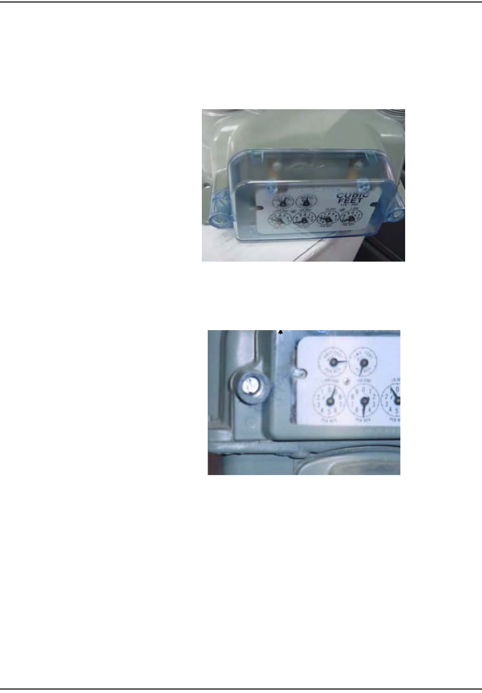
2Removetheindexandindexscrewsfromthemeter.Inspecttheindexforany
signsofdamage.Ifdamaged,replacetheindex.RefertoAppendix B,Visual
InspectionofIndexesformoreinformation.Alsoremovealloftheoriginal
gasketmaterial,ifany.
Figure 5.28 Sprague/Schlumberger/Actaris: Removing the index
3Cleantheareabehindtheindexandthecovergasketsurfaceonthemeter
withawirebrushandgasketscraper.Ensuretheentireareaisfreeofdebris.
Figure 5.29 Sprague/Schlumberger/Actaris: Removal of index cover gasket
oÉëáÇÉåíá~ä=jÉíÉê=jçÇìäÉ=oÉíêçÑáí
RJNS `ÉääåÉí=d~ë=jçÇìäÉ=~åÇ=jÉíÉê=fåëí~ää~íáçå=dìáÇÉ
4InsertthetwoPhillipsheadscrewsthroughtheMeterModulebase.
Figure 5.30 Sprague/Schlumberger/Actaris: Meter Module pre-assembled
5AligntheMeterModulebasetothemeter.LeadtheIndexscrewsintothe
meter.Ensurethatthemoduleʹswigglerandthemeterʹsdrivedogarealigned
properly.Onlyengagescrews1turn,leaveclearancetoslidetheindexunder
thescrewheads.
Figure 5.31 Sprague/Schlumberger/Actaris: Alignment of the meter drive dog and screws
Figure 5.32 Sprague/Schlumberger/Actaris: Meter Module base attached to meter, ready to slide on
dials
oÉëáÇÉåíá~ä=jÉíÉê=jçÇìäÉ=oÉíêçÑáí
`ÉääåÉí=d~ë=jçÇìäÉ=~åÇ=jÉíÉê=fåëí~ää~íáçå=dìáÇÉ RJNT
6Installtheindexbyslidingthetabsontheindexundertheheadsofthescrew
andtighteningthescrews.Thetorquerequirementis4‐8inch‐pounds.Ensure
thatthemoduleʹswigglerandthemeterdrivedogoftheindexareproperly
alignedbeforetighteningthescrews.Alsoensurethatthemoduleisnot
boundupbycheckingthe2Footdialtoensurethatithasbetween1/4and1/2
turnplayinit.
Figure 5.33 Sprague/Schlumberger/Actaris: Securing index and checking for free movement of
wiggler-
oÉëáÇÉåíá~ä=jÉíÉê=jçÇìäÉ=oÉíêçÑáí
RJNU `ÉääåÉí=d~ë=jçÇìäÉ=~åÇ=jÉíÉê=fåëí~ää~íáçå=dìáÇÉ
7Plugthebatteryintotheprogrammingpowercableandplaceitintothe
batterycompartmentwiththebatterywiresandconnectorinback(see
Figures36,37,and38).
Figure 5.34 Sprague/Schlumberger/Actaris: Connecting the Battery
Figure 5.35 Sprague/Schlumberger/Actaris: Correct Battery Orientation
Figure 5.36 Sprague/Schlumberger/Actaris: Battery Correctly Installed
oÉëáÇÉåíá~ä=jÉíÉê=jçÇìäÉ=oÉíêçÑáí
`ÉääåÉí=d~ë=jçÇìäÉ=~åÇ=jÉíÉê=fåëí~ää~íáçå=dìáÇÉ RJNV
8UsetheremainingtwoscrewstoinstallthecoverontheMeterModule,
tighteningthescrewsuntilthecoversitssnug,thentightenanadditional
quarterturn.Insertthetworedtamperseals.
Figure 5.37 Sprague/Schlumberger/Actaris: Fasten Cover Screws and Insert Tamper seals
9UtilizetheRFBustertoverifymoduleistransmitting,holdtheRFBusterwith
magnetsidetothetopupperleftquadrantofthemoduleplasticandholdthe
buttonuntil10beepsarereceived.
10 Cleanupanydebrisfromtheretrofitandinstallationprocesses,andleavea
doorhangertagwithanyappropriateinformationfilledin,ifdoorhangers
arespecifiedduringinstallertrainingforthatutility.
11 Attheendoftheday,theinstallerreturnstotheCrossDockforthecheck‐in
process.Theinstallershouldalsoturnininventoryofunused,defective,or
brokengasMeterModules.TheinstallermustcheckinallHandheldsissued
atthestartoftheshift.Theinstallerisresponsibleforreconcilingany
discrepanciesinchangeoutdatabeforethecheck‐inprocesscanbe
completed.MeterModuleswillnotbecheckedouttoaninstallerwhohasnot
completedthepreviousdayʹscheck‐inprocess.
oÉëáÇÉåíá~ä=jÉíÉê=jçÇìäÉ=oÉíêçÑáí
RJOM `ÉääåÉí=d~ë=jçÇìäÉ=~åÇ=jÉíÉê=fåëí~ää~íáçå=dìáÇÉ
Lancaster/National Meter Module Installation
BeforebeginningtheLancasterretrofit,ensurethatthemeterisretrofittable.You
canidentifythisbytheplacementofthescrewsthatattachthedialstothe
module.Itisveryimportantthatyoudonotbreakthesealofthemeterdialcover
ifthisisnotaretrofittablemeter.
Figure 5.38 Lancaster/National: Meter retrofittable
Figure 5.39 Lancaster/National: Meter non-retrofittable
oÉëáÇÉåíá~ä=jÉíÉê=jçÇìäÉ=oÉíêçÑáí
`ÉääåÉí=d~ë=jçÇìäÉ=~åÇ=jÉíÉê=fåëí~ää~íáçå=dìáÇÉ RJON
Figure 5.40 Lancaster/National: Meter Module before installation
Figure 5.41 Lancaster/National: Meter
1Followsteps1‐4inʺToBeginResidentialMeterModuleRetrofitʺonpage 5‐1.
Figure 5.42 Lancaster/National: Removing the index cover
oÉëáÇÉåíá~ä=jÉíÉê=jçÇìäÉ=oÉíêçÑáí
RJOO `ÉääåÉí=d~ë=jçÇìäÉ=~åÇ=jÉíÉê=fåëí~ää~íáçå=dìáÇÉ
2Removetheindexfromthemeter.
Figure 5.43 Lancaster/National: Removing the index
3Removealloftheoriginalgasketmaterial,ifany.Cleantheareabehindthe
indexandthecovergasketsurfaceonthemeterwithawirebrushandgasket
scraper,ensurethattheentireareaisfreeofdebris.
Figure 5.44 Lancaster/National: Removal of index cover gasket
oÉëáÇÉåíá~ä=jÉíÉê=jçÇìäÉ=oÉíêçÑáí
`ÉääåÉí=d~ë=jçÇìäÉ=~åÇ=jÉíÉê=fåëí~ää~íáçå=dìáÇÉ RJOP
4Removeoriginalone‐prongcouplerandreplacewithtwo‐prongedcoupler,
beingcarefulnottocrossthethreads.Thisdoesnothavetobetightenedsince
themeterturningwillkeeptensiononthedrivedog.
Figure 5.45 Lancaster/National: Installation of New Coupler
5InsertthetwolongerscrewsthroughtheMeterModulebase.
Figure 5.46 Lancaster/National: Meter Module pre-assembled
oÉëáÇÉåíá~ä=jÉíÉê=jçÇìäÉ=oÉíêçÑáí
RJOQ `ÉääåÉí=d~ë=jçÇìäÉ=~åÇ=jÉíÉê=fåëí~ää~íáçå=dìáÇÉ
6 FastentheMeterModulebasetothemeter,ensuringthatthemoduleʹs
wigglerandmeterʹsdrivedogareproperlyaligned.Onlyengagescrews1
turn.
Figure 5.47 Lancaster/National: Alignment of the meter drive dog and screws
Figure 5.48 Lancaster/National: Meter Module base attached to meter, ready to slide on dials
7Installtheindexbyslidingthetabsontheindexundertheheadsofthescrew
andtighteningthescrews.Thetorquerequirementis10inch‐pounds.Ensure
thatthemoduleʹswigglerandthemeterdrivedogoftheindexareproperly
alignedbeforetighteningthescrews.Alsoensurethatthemoduleisnot
boundupbycheckingthe2Footdialtoensurethatithasbetween1/4and1/2
turnplayinit.SecuringIndexandCheckingforFreeMovementofDrive
Dog.
oÉëáÇÉåíá~ä=jÉíÉê=jçÇìäÉ=oÉíêçÑáí
`ÉääåÉí=d~ë=jçÇìäÉ=~åÇ=jÉíÉê=fåëí~ää~íáçå=dìáÇÉ RJOR
8Plugthebatteryintotheprogrammingport/powercableandplaceitintothe
batterycompartmentwiththebatterywiresandconnectorinback.
Figure 5.49 Lancaster/National: Connecting the Battery
Figure 5.50 Lancaster/National: Correct Battery Orientation
oÉëáÇÉåíá~ä=jÉíÉê=jçÇìäÉ=oÉíêçÑáí
RJOS `ÉääåÉí=d~ë=jçÇìäÉ=~åÇ=jÉíÉê=fåëí~ää~íáçå=dìáÇÉ
Figure 5.51 Lancaster/National: Battery Correctly Installed
9UsetheremainingtwoscrewstoinstallthecoverontheMeterModule,
tighteningthescrewsuntilthecoversitssnug,thentightenasadditional
quarterturn.Insertthetworedtamperseals.
Figure 5.52 Lancaster/National: Fasten Cover Screws and Insert Tamper seals
oÉëáÇÉåíá~ä=jÉíÉê=jçÇìäÉ=oÉíêçÑáí
`ÉääåÉí=d~ë=jçÇìäÉ=~åÇ=jÉíÉê=fåëí~ää~íáçå=dìáÇÉ RJOT
10 Ifneeded,removeserialnumberplatefromoriginalcoverandinstallonnew
coverwithtwosmallscrewsprovided.
Figure 5.53 Lancaster/National: Replacing Serial Number Plate
11 UtilizetheRFBustertoverifymoduleistransmitting,holdtheRFBusterwith
magnetsidetothetopupperleftquadrantofthemoduleplasticcoverand
holdthebuttonuntil10beepsarereceived.SeeAppendix C,UsingtheRF
Busterformoreinformation.

Notes:
RJOU `ÉääåÉí=d~ë=jçÇìäÉ=~åÇ=jÉíÉê=fåëí~ää~íáçå=dìáÇÉ
oÉëáÇÉåíá~ä=jÉíÉê=jçÇìäÉ=oÉíêçÑáí

`ÉääåÉí=d~ë=jçÇìäÉ=~åÇ=jÉíÉê=fåëí~ää~íáçå=dìáÇÉ SJN
CHAPTER 6 COMMERCIAL AND INDUSTRIAL METER MODULE
INSTALLATION
Thischapteroutlineschangeoutproceduresfor:
•AmericanCG3
• Rockwell/Equimeter/SensusMeterModuleInstallation
•Sprague/ActarisMeterModuleInstallation
•Schlumberger/ActarisMeterModuleInstallation
RefertoAppendix E,Difficult/Non‐compatibleCommercialRetrofitsfordifficultand
non‐compatiblemoduleinstallationinstructions.
TO BEGIN C&I METER MODULE INSTALLATION
Thefirstfourstepsforeverygasmetermoduleinstallarethesameforevery
manufacturer.Priortobeginningthecommercialmetermoduleretrofit,make
sureyouhavefollowedthestepsinʺIftheinstallerscomeacrossanymeterswherea
medicalalertcodeappearsintheHandheldforthataddresstheyaretodiscontinuethe
exchange,entertheappropriateskipcodeandmovetothenextexchange.PriortoMeter
ExchangeorModuleRetrofitʺonpage 3‐1.
1RemovethecoverfromtheMeterModule.
2PlugtheprogrammingcablefromtheHandheldintotheprogramming
powercableontheMeterModule.RefertoChapter 2,UsingtheHandHeld
Device.
3ProgramtheMeterModuleandchecktheHandheldforsuccessful
programming(example,Dials=4,MeterID=0123456G,MeterConstant=2).
4Removethetampersealsandindexcoverfromtheoriginalgasmeter.
`çããÉêÅá~ä=~åÇ=fåÇìëíêá~ä=jÉíÉê=jçÇìäÉ=fåëí~ää~íáçå
SJO `ÉääåÉí=d~ë=jçÇìäÉ=~åÇ=jÉíÉê=fåëí~ää~íáçå=dìáÇÉ
American CG3 Installation
Figure 6.1 American CG3: Meter before installation
1FollowthestepsinʺToBeginC&IMeterModuleInstallationʺonpage 6‐1.
2Removethetampercapsandindexcoverfromtheoriginalmeter.Remove
theindexfromtheindexcover.Cleantheworkareaswithawirebrushand/
orscraperasneeded.Removealloftheoriginalgasketifitisunserviceable.
InspectIndexforwearandgearfading.
Figure 6.2 American CG3:Removing the cover and index
`çããÉêÅá~ä=~åÇ=fåÇìëíêá~ä=jÉíÉê=jçÇìäÉ=fåëí~ää~íáçå
`ÉääåÉí=d~ë=jçÇìäÉ=~åÇ=jÉíÉê=fåëí~ää~íáçå=dìáÇÉ SJP
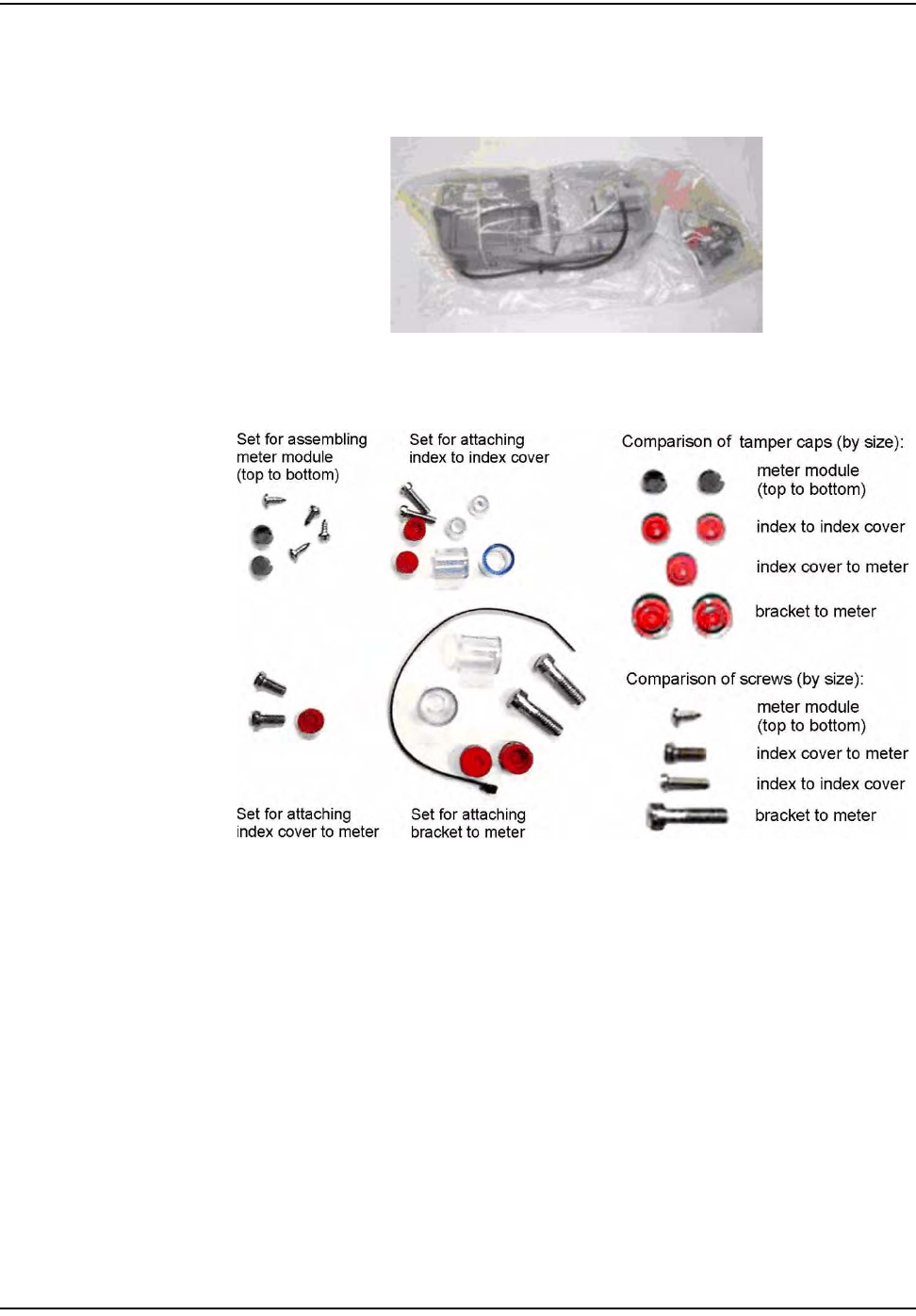
3OpenthepackagecontainingtheMeterModule,screws,andbattery.
Figure 6.3 Common American meter module packaging with hardware on the right
Figure 6.4 American CG3: screw kit
`çããÉêÅá~ä=~åÇ=fåÇìëíêá~ä=jÉíÉê=jçÇìäÉ=fåëí~ää~íáçå
SJQ `ÉääåÉí=d~ë=jçÇìäÉ=~åÇ=jÉíÉê=fåëí~ää~íáçå=dìáÇÉ
Figure 6.5 American CG3: meter module kit
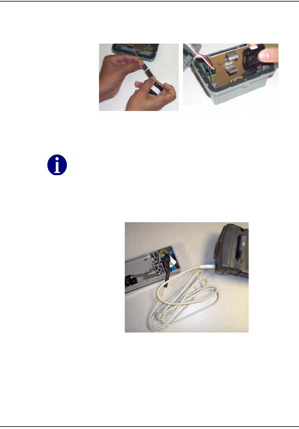
4Openthebagcontainingthebattery.Carefullyremovethebattery.
5Openthemetermodule.Avoidpullingthecables.
Figure 6.6 Open American CG3: module
`çããÉêÅá~ä=~åÇ=fåÇìëíêá~ä=jÉíÉê=jçÇìäÉ=fåëí~ää~íáçå
`ÉääåÉí=d~ë=jçÇìäÉ=~åÇ=jÉíÉê=fåëí~ää~íáçå=dìáÇÉ SJR
6 ConnectthebatterytotheMeterModule.Assemblethebatteryintothe
retainingcliponthemetalbracket.
Figure 6.7 American CG3:Connecting the battery to the module
7 Connecttheprogrammingcablefromthehandheldcomputertothe
programmingportontheMeterModule.ProgramtheMeterModule.Check
thehandheldforsuccessfulprogramming(example‐Dials=4or5,MeterID
=0123456G,MeterConstant=5or10).
Figure 6.8 American CG3:Connecting the programming cable to the American Commercial meter
module
Route wire through cutout area so that wire is not pinched.
`çããÉêÅá~ä=~åÇ=fåÇìëíêá~ä=jÉíÉê=jçÇìäÉ=fåëí~ää~íáçå
SJS `ÉääåÉí=d~ë=jçÇìäÉ=~åÇ=jÉíÉê=fåëí~ää~íáçå=dìáÇÉ
Figure 6.9 American CG3: module route wire
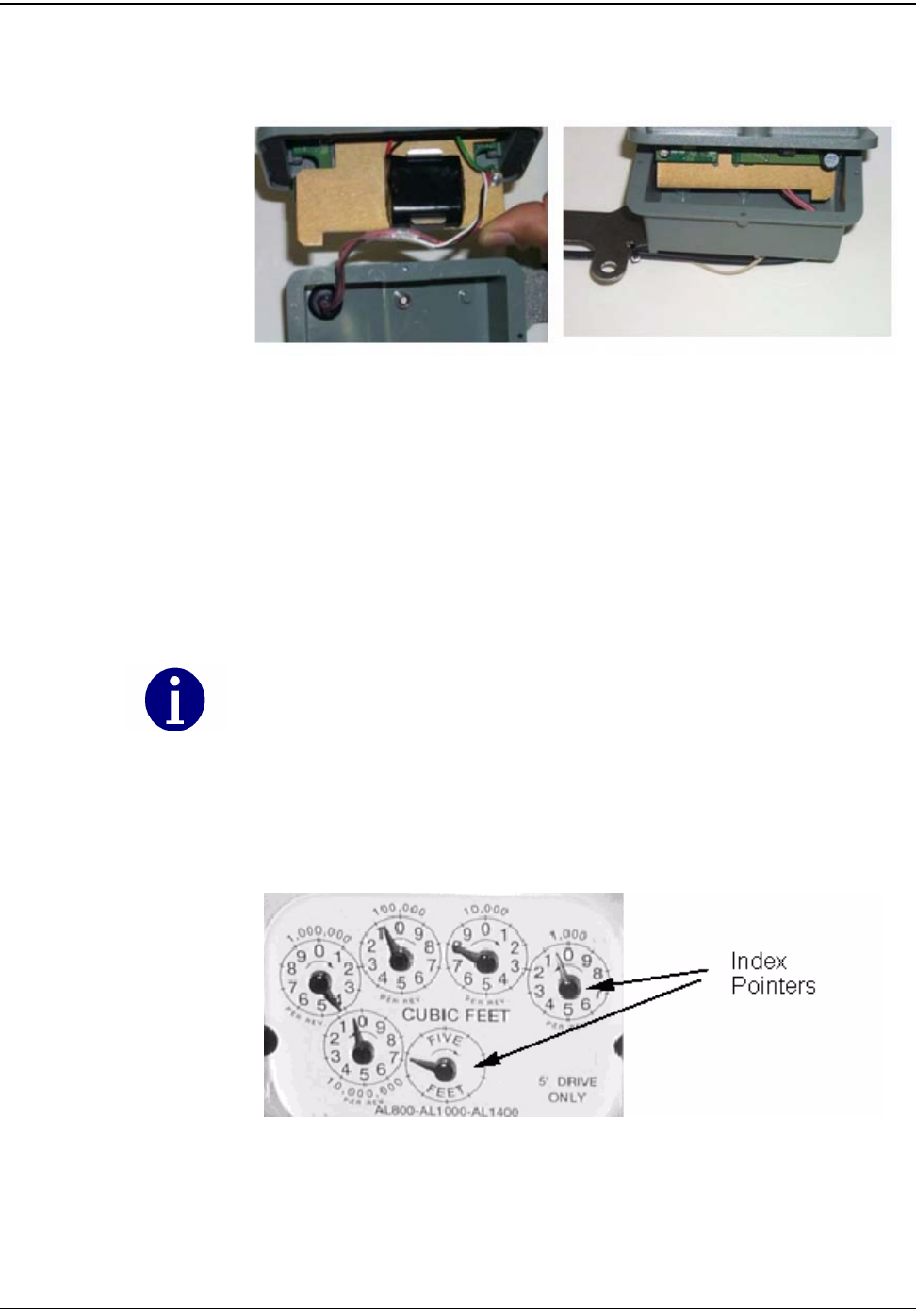
8Slidethemetalbracket(notthegreencircuitboard)intotheslotsofthe
clamshell(oneoftheclamshellhalveshasslotsonoppositesidesofthe
interior).Ifyouarelookingdownintotheslots,thebatteryclipshouldbe
towardsthetop‐thelargecapacitorsonthecircuitboardgodeepintothe
clamshell.AssembletheMeterModulehalvestogetherwiththefoursmall
self‐tappingscrewsprovided.Thetorquerequirementis6‐10inchpounds.
Ensurethatthegasketisinplaceandthewiresarenotpinched.Installthe
tamperseals.
Figure 6.10 American CG3: module Index detail
Check condition of the index for looseness of index pointers on shaft, cracks on face
enamel, or peeling. Ensure that the index is not bound up. Replace the index if dials are
loose or locked, or if the enamel is cracked, loose or damaged.
`çããÉêÅá~ä=~åÇ=fåÇìëíêá~ä=jÉíÉê=jçÇìäÉ=fåëí~ää~íáçå
`ÉääåÉí=d~ë=jçÇìäÉ=~åÇ=jÉíÉê=fåëí~ää~íáçå=dìáÇÉ SJT
9 Attachthenewindexcovertotheindexusingthescrewsprovided.The
torquerequirementis10‐inchpounds.Handletheindexcarefullytoavoid
breakingthecounterorindex.Ensurethatthecounterandindexareproperly
aligned.Verifythatthecounterisfullyengagedtotheindexpointer.
Figure 6.11 American CG3:module- Attaching the new Index cover
10 Attachtampersealsasshown.therearetwotampersealsfortheIndex‐to‐
Indexcoverconnections.
Figure 6.12 American CG3: tamper sealing for Index cover
`çããÉêÅá~ä=~åÇ=fåÇìëíêá~ä=jÉíÉê=jçÇìäÉ=fåëí~ää~íáçå
SJU `ÉääåÉí=d~ë=jçÇìäÉ=~åÇ=jÉíÉê=fåëí~ää~íáçå=dìáÇÉ
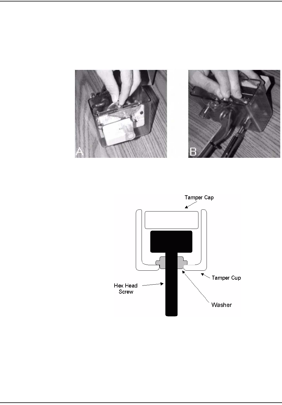
11 Mounttheindexandcoverontothemeter.Placethegasketonthemeter
(replaceifnecessary),aligningtheholes.Securetheindextothemeterwith
thetwohex‐headscrewsprovided.Thetorquerequirementis20‐30inch
pounds.Installthetamperseal.
Figure 6.13 American CG3:l installing Index
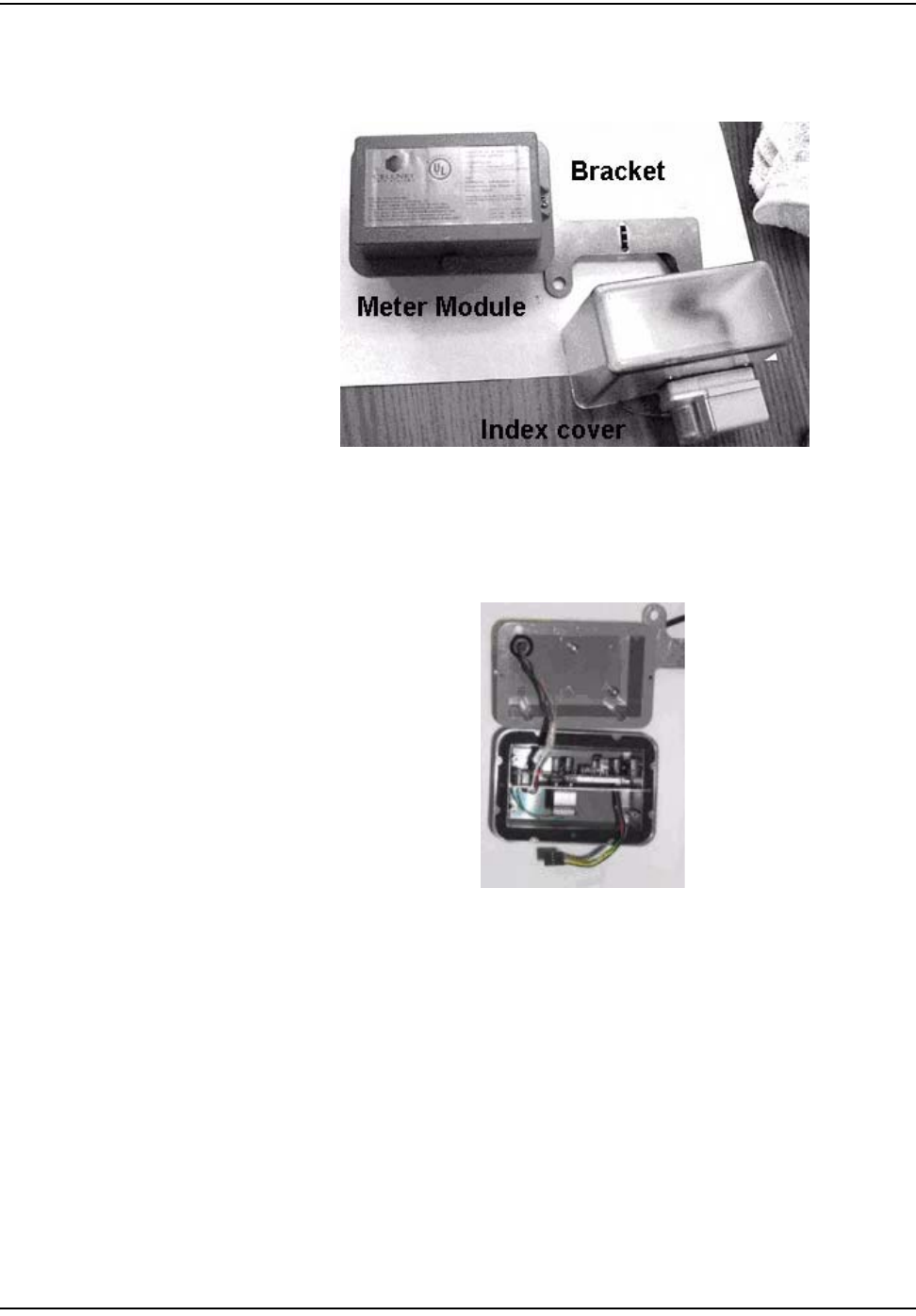
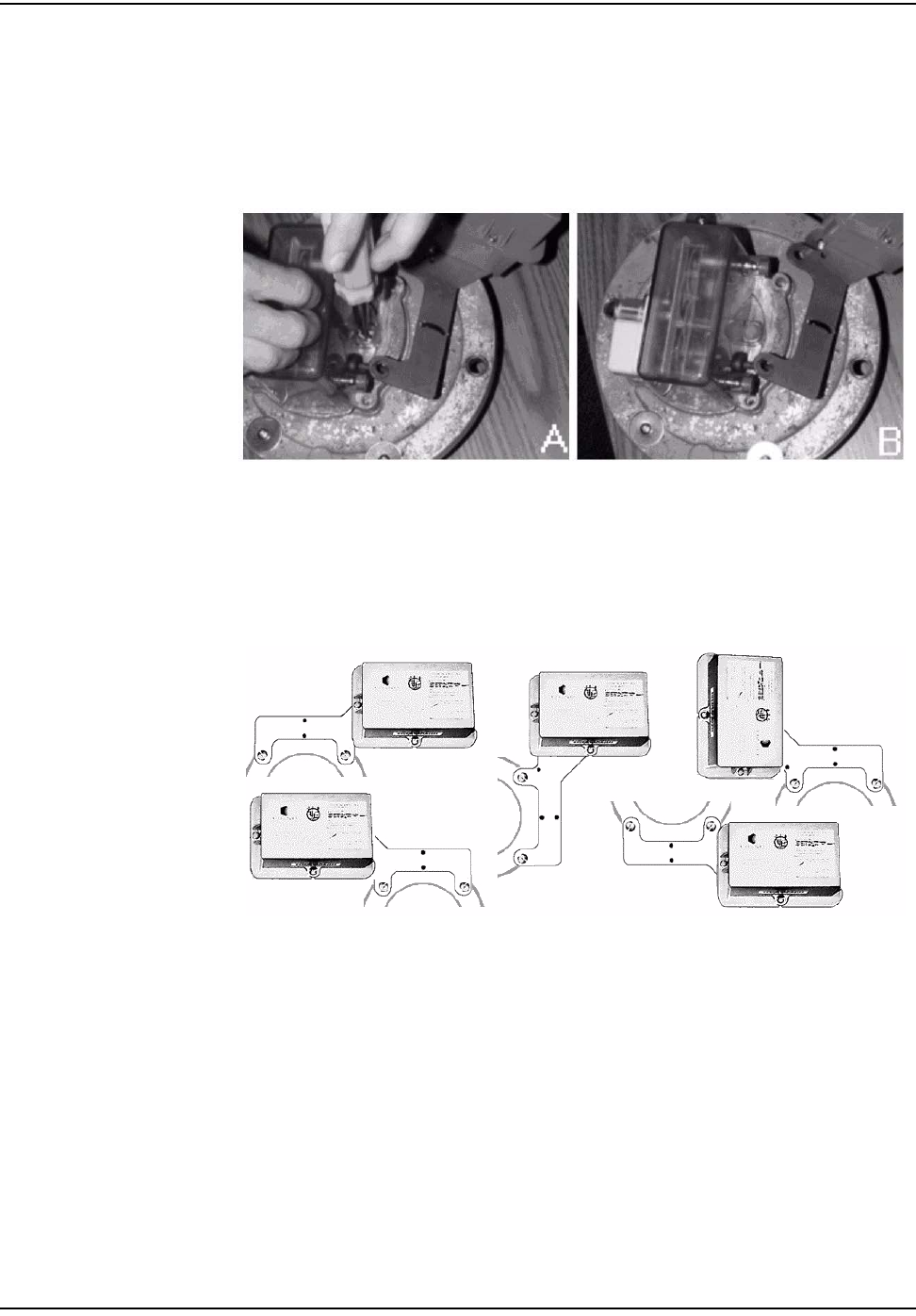
12 Determinethebestorientationforthemountingbracket(seefollowing
configurations).Tochangethebracketorientation,removethetwoPhillips
headscrewsholdingthebrackettothemodule.Thebracketcanbeturnedor
flippedoverforthebestconfiguration.Cabletiemayneedtoberemoved.
Figure 6.14 American CG3: mounting bracket configurations
`çããÉêÅá~ä=~åÇ=fåÇìëíêá~ä=jÉíÉê=jçÇìäÉ=fåëí~ää~íáçå
`ÉääåÉí=d~ë=jçÇìäÉ=~åÇ=jÉíÉê=fåëí~ää~íáçå=dìáÇÉ SJV
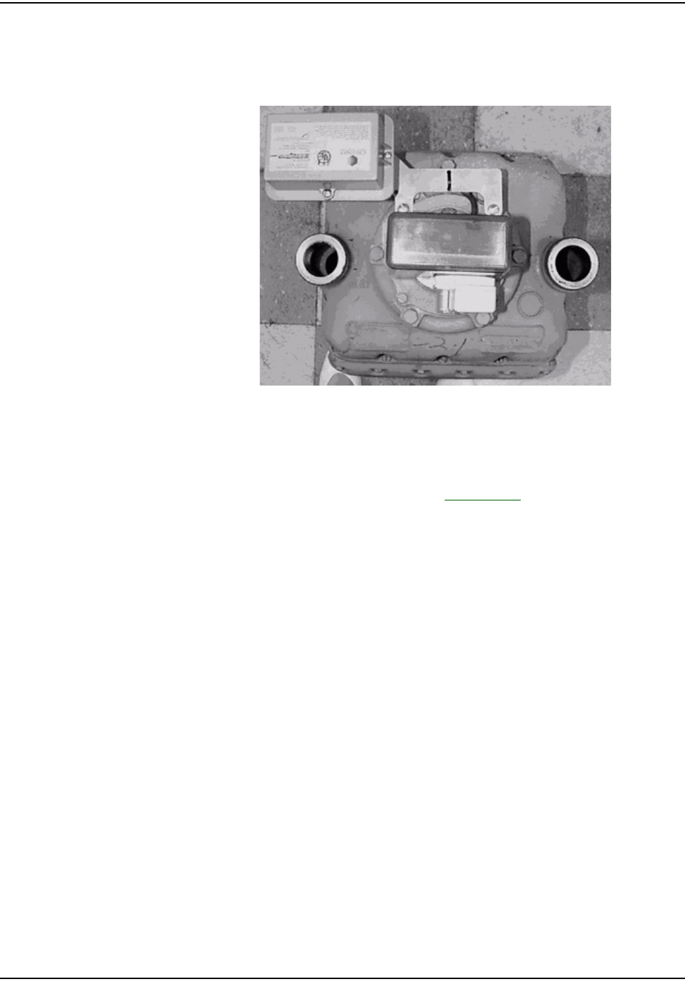
13 AttachthemountingbrackettothemeterusingthelargeFillisterscrews
provided.Useatampercupsealononeortwoofthescrews.Thetorque
requirementis30‐40inchpounds.Installthetwotamperseals.
Figure 6.15 American CG3:meter module with mounting bracket installed
14 Installtampercapsoverremainingfivescrews.
15 UtilizetheRFBustertoverifymoduleistransmitting,holdRFBusterwith
magnetsidetothetopupperleftquadrantofthemoduleplasticandholdthe
buttonuntil10beepsarereceived.SeeAppendix C,UsingtheRFBusterfor
moreinformation.
16 Cleanupanydebrisfromtheretrofitandinstallationprocessesandtieany
loosecableswithtiewraps.
17 Proceedtothenextinstallationsite.
18 Attheendoftheday,returntotheCrossDockforthecheck‐inprocess.Turn
ininventoryofunused,defective,orbrokengasMeterModules.Checkinthe
handheldcomputer.Theinstallermustreconcileanydiscrepanciesinthe
changeoutdatabeforethecheck‐inprocesscanbecompleted.Thecrossdock
willnotcheckoutanyMeterModulestoaninstallerwhohasnotcompleted
thepreviousdayʹscheck‐inprocess.
Rockwell/Equimeter/Sensus Meter Module Installation
TherearetwotypesofRockwellmodules:CenterandOffset.Theleftside
illustratescenterprovingdialandtherightsideillustratesoffsetproving
dial.Verifytheappropriatetypebeforestartinginstallation.
`çããÉêÅá~ä=~åÇ=fåÇìëíêá~ä=jÉíÉê=jçÇìäÉ=fåëí~ää~íáçå
SJNM `ÉääåÉí=d~ë=jçÇìäÉ=~åÇ=jÉíÉê=fåëí~ää~íáçå=dìáÇÉ
Figure 6.16 Rockwell/Equimeter/Sensus: Indexes before installation
1FollowthestepsinʺToBeginC&IMeterModuleInstallationʺonpage 6‐1.
2Removethetampercapsandindexcoverfromtheoriginalmeter.Removeall
oftheoriginalgasketifitisunserviceable.Cleantheworkareawithawire
brushandscraperifneeded.
3SelecttheappropriateMeterModule(Rockwell/EquimeterCenterorOffset).
OpenthepackagecontainingtheMeterModule,screws,andbattery.
Figure 6.17 Rockwell/Equimeter/Sensus: screw and meter module kits
4Openthebagcontainingthebattery.Carefullyremovethebattery.
5OpentheMeterModule,takingcaretoavoidpullingonthecables.
6 ConnectthebatterytotheMeterModule.Assemblethebatteryintothe
retainingcliponthemetalbracket.
7 Connecttheprogrammingcablefromthehandheldcomputertothe
programmingportontheMeterModule.ProgramtheMeterModule.Check
thehandheldforsuccessfulprogramming
8Slidethemetalbracket(notthegreencircuitboard)intotheslotsofthe
clamshell(oneoftheclamshellhalveshasslotsonoppositesidesofthe
interior).Ifyouarelookingdownintotheslots,thebatteryclipshouldbe
towardsthetop‐thelargecapacitorsonthecircuitboardgodeepintothe
clamshell.
`çããÉêÅá~ä=~åÇ=fåÇìëíêá~ä=jÉíÉê=jçÇìäÉ=fåëí~ää~íáçå
`ÉääåÉí=d~ë=jçÇìäÉ=~åÇ=jÉíÉê=fåëí~ää~íáçå=dìáÇÉ SJNN
9 AssembletheMeterModulehalvestogetherwiththefoursmallself‐tapping
screwsprovided.Thetorquerequirementis6‐10inchpounds.Ensurethatthe
gasketisinplaceandthewiresarenotpinched.Installthetamperseals.
10 Installthenewindexcover.Gentlyslidethecoverovertheindextoavoid
breakingthecounter.Becarefulnottodamagethedials.Ensurethatthe
counterandindexesareproperlyaligned.Verifythatthecounterisfully
engagedtotheindexpointers.
Figure 6.18 Rockwell/Equimeter/Sensus: meter module installing Index cover
11 AttachthecoverandMeterModuletothemeter.Positionthemodule
bracketoverthecoverandalignthescrewholes.Thetorquerequirementis
30‐40inchpounds.
Figure 6.19 Rockwell/Equimeter/Sensus: securing index cover & Meter Module
Check condition of the index for looseness of index pointers on shaft, cracks on face
enamel, or peeling. Replace the index if dials are loose or bound up, or if enamel is cracked
or loose.
`çããÉêÅá~ä=~åÇ=fåÇìëíêá~ä=jÉíÉê=jçÇìäÉ=fåëí~ää~íáçå
SJNO `ÉääåÉí=d~ë=jçÇìäÉ=~åÇ=jÉíÉê=fåëí~ää~íáçå=dìáÇÉ
12 Installnewtampersealsovertwoscrewsusingtheplasticsleeveprovided
(optional).
Figure 6.20 Rockwell/Equimeter/Sensus: center test dial, counter installed, or index
13 UtilizetheRFBustertoverifymoduleistransmitting,holdRFBusterwith
magnetsidetothetopupperleftquadrantofthemoduleplasticandholdthe
buttonuntil10beepsarereceived.SeeAppendix C,UsingtheRFBusterfor
moreinformation.
14 Cleanupanydebrisfromtheretrofitandinstallationprocessesandtieany
loosecableswithtiewraps.
15 Proceedtothenextinstallationsite.
16 Attheendoftheday,returntotheCrossDockforthecheck‐inprocess.Turn
ininventoryofunused,defective,orbrokengasMeterModules.Checkinall
handheldcomputersissued.Youmustreconcileanydiscrepanciesinthe
changeoutdatabeforethecheck‐inprocesscanbecompleted.MeterModules
willnotbecheckedouttoaninstallerwhohasnotcompletedtheprevious
dayʹscheck‐inprocess.
Sprague/Actaris Meter Module Installation
Figure 6.21 Sprague/Actaris: Indexes before installation
`çããÉêÅá~ä=~åÇ=fåÇìëíêá~ä=jÉíÉê=jçÇìäÉ=fåëí~ää~íáçå
`ÉääåÉí=d~ë=jçÇìäÉ=~åÇ=jÉíÉê=fåëí~ää~íáçå=dìáÇÉ SJNP
1FollowthestepsinʺToBeginC&IMeterModuleInstallationʺonpage 6‐1.
2Removethetampercapsandindexcoverfromtheoriginalmeter.Removeall
oftheoriginalgasketmaterial.Cleanthegasketsurfaceonthemeterwitha
wirebrushandgasketscraper.
3OpenthepackagecontainingtheMeterModule,screws,andbattery.
Figure 6.22 Sprague/Actaris: screw kit
4Openthebagcontainingthebattery.Carefullyremovethebattery.
5OpentheMeterModule,takingcaretoavoidpullingonthecables.
6 ConnectthebatterytotheMeterModule.Assemblethebatteryintothe
retainingcliponthemetalbracket.
7 Connecttheprogrammingcablefromthehandheldcomputertothe
programmingportonthereplacementMeterModule.ProgramtheMeter
Module.Checkthehandheldforsuccessfulprogramming.
8Slidethemetalbracket(notthegreencircuitboard)intotheslotsofthe
clamshell(oneoftheclamshellhalveshasslotsonoppositesidesofthe
interior).Ifyouarelookingdownintotheslots,thebatteryclipshouldbe
towardsthetop‐thelargecapacitorsonthecircuitboardgodeepintothe
clamshell.AssembletheMeterModulehalvestogetherwiththefoursmall
self‐tappingscrewsprovided.Thetorquerequirementis6‐10inchpounds.
Ensurethatthegasketisinplaceandthewiresarenotpinched.Installthe
tamperseals.
9Slidethebracketbetweentheindexcoverandthemeter.
Check condition of the index for looseness of index pointers on shaft, cracks on face
enamel, or peeling. Replace the index if dials are loose or if enamel is cracked or loose.
`çããÉêÅá~ä=~åÇ=fåÇìëíêá~ä=jÉíÉê=jçÇìäÉ=fåëí~ää~íáçå
SJNQ `ÉääåÉí=d~ë=jçÇìäÉ=~åÇ=jÉíÉê=fåëí~ää~íáçå=dìáÇÉ
10 Installthenewgasket(ifrequired)andindexcovertothefrontoftheindex.
Handletheindexcarefully.Thetorquerequirementis30‐40inchpounds.
Thescrewsgothroughtheindexcoverandbracket,andfastenintothemeter.
Figure 6.23 Sprague/Actaris: installing Index cover
11 Installnewtamperseals.
Figure 6.24 Sprague/Actaris: installed tamper seals
Ensure that the counter is aligned with proving dial (on top).
`çããÉêÅá~ä=~åÇ=fåÇìëíêá~ä=jÉíÉê=jçÇìäÉ=fåëí~ää~íáçå
`ÉääåÉí=d~ë=jçÇìäÉ=~åÇ=jÉíÉê=fåëí~ää~íáçå=dìáÇÉ SJNR
12 UtilizetheRFBustertoverifymoduleistransmitting,holdRFBusterwith
magnetsidetothetopupperleftquadrantofthemoduleplasticandholdthe
buttonuntil10beepsarereceived.SeeAppendix C,UsingtheRFBusterfor
moreinformation.
Figure 6.25 Sprague/Actaris: meter with module installed
13 Cleanupanydebrisfromtheretrofitandinstallationprocessesandtieany
loosecableswithtiewraps.
14 Proceedtothenextinstallationsite.
15 Attheendoftheday,returntotheCrossDockforthecheck‐inprocess.Turn
ininventoryofunused,defective,orbrokengasMeterModules.Checkinall
handheldcomputersissued.Youmustreconcileanydiscrepanciesinthe
changeoutdatabeforethecheck‐inprocesscanbecompleted.MeterModules
willnotbecheckedouttoaninstallerwhohasnotcompletedtheprevious
dayʹscheck‐inprocess.
`çããÉêÅá~ä=~åÇ=fåÇìëíêá~ä=jÉíÉê=jçÇìäÉ=fåëí~ää~íáçå
SJNS `ÉääåÉí=d~ë=jçÇìäÉ=~åÇ=jÉíÉê=fåëí~ää~íáçå=dìáÇÉ
Schlumberger/Actaris Meter Module Installation
Figure 6.26 Schlumberger/Actaris: before installation
Figure 6.27 Schlumberger/Actaris: meter with short base
1FollowthestepsinʺToBeginC&IMeterModuleInstallationʺonpage 6‐1.
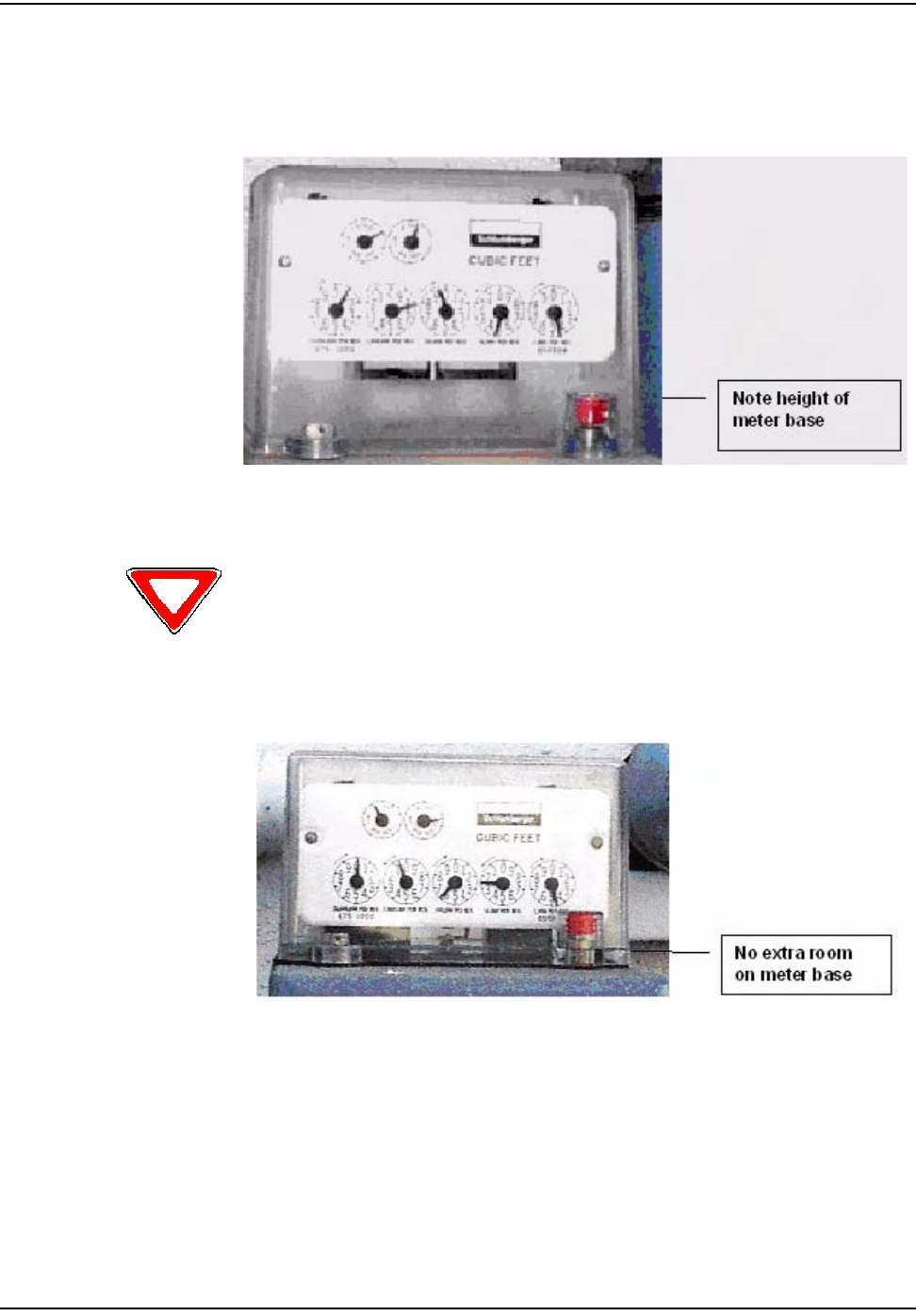
Only Schlumberger meters with the taller base (shown above) can accommodate Cellnet
Meter Modules. Meters with the shorter base (shown below) will need to be retrofitted with
a taller index bracket prior to module retrofit.
`çããÉêÅá~ä=~åÇ=fåÇìëíêá~ä=jÉíÉê=jçÇìäÉ=fåëí~ää~íáçå
`ÉääåÉí=d~ë=jçÇìäÉ=~åÇ=jÉíÉê=fåëí~ää~íáçå=dìáÇÉ SJNT
2Removethetampercapsandindexcoverfromtheoriginalmeter.Remove
thegasketifitisunserviceable.Cleantheworkareaswithawirebrushor
scraperasneeded.
Figure 6.28 Schlumberger/Actaris: Index cover removed
3OpenthepackagecontainingtheMeterModule,screws,andbattery.
4Openthebagcontainingthebattery.Carefullyremovethebattery.
5OpentheMeterModule,takingcaretoavoidpullingonthecables.
6 Connecttheprogrammingcablefromthehandheldcomputertothe
programmingportontheMeterModule.ProgramtheMeterModule.Check
thehandheldforsuccessfulprogramming.
7 ConnectthebatterytotheMeterModule.Assemblethebatteryintothe
retainingcliponthemetalbracket.
8Slidethemetalbracket(notthegreencircuitboard)intotheslotsofthe
clamshell(oneoftheclamshellhalveshasslotsonoppositesidesofthe
interior).Ifyouarelookingdownintotheslots,thebatteryclipshouldbe
towardsthetop‐thelargecapacitorsonthecircuitboardgodeepintothe
clamshell.AssembletheMeterModulehalvestogetherwiththefoursmall
self‐tappingscrewsprovided.Thetorquerequirementis6‐10inchpounds.
Ensurethatthegasketisinplaceandthewiresarenotpinched.Installthe
tamperseals.
9Installthenewindexcover.Gentlyslidethecoverovertheindextoavoid
breakingthecounter.Becarefulnottodamagethedials.
Check condition of the index for looseness of index pointers on shaft, cracks on face
enamel, or peeling. Replace the index if dials are loose or if enamel is cracked or loose.
`çããÉêÅá~ä=~åÇ=fåÇìëíêá~ä=jÉíÉê=jçÇìäÉ=fåëí~ää~íáçå
SJNU `ÉääåÉí=d~ë=jçÇìäÉ=~åÇ=jÉíÉê=fåëí~ää~íáçå=dìáÇÉ
10 AttachthebracketandMeterModuletothemeter.Notetheorderof
installation:indexcover,bracket,tampercap,andscrew.Thetorque
requirementis30‐40inchpounds.
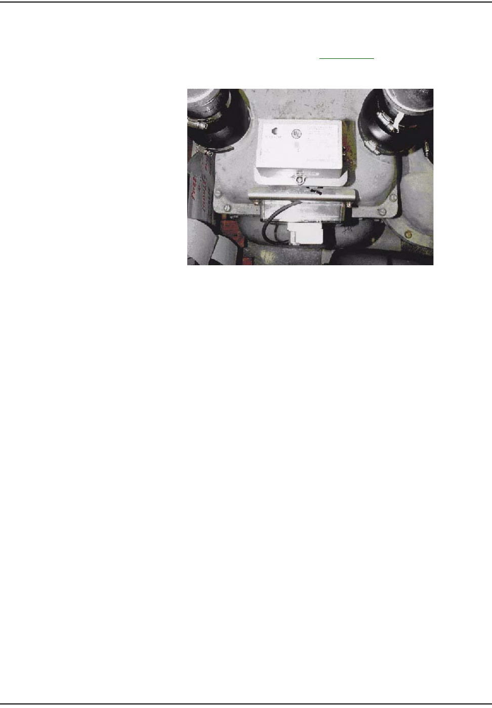
Figure 6.29 Schlumberger/Actaris: meter with bracket and meter module
11 Installnewtampercapsoverthescrewsusingtheplasticsleevesprovided.
12 UtilizetheRFBustertoverifymoduleistransmitting,holdRFBusterwith
magnetsidetothetopupperleftquadrantofthemoduleplasticandholdthe
buttonuntil10beepsarereceived.SeeAppendix C,UsingtheRFBusterfor
moreinformation.
13 Cleanupanydebrisfromtheretrofitandinstallationprocessesandtieany
loosecableswithtiewraps.
14 Proceedtothenextinstallationsite.
15 Attheendoftheday,returntotheCrossDockforthecheck‐inprocess.Turn
ininventoryofunused,defective,orbrokengasMeterModules.Checkinall
handheldcomputersissued.Youmustreconcileanydiscrepanciesinthe
changeoutdatabeforethecheck‐inprocesscanbecompleted.MeterModules
willnotbecheckedouttoaninstallerwhohasnotcompletedtheprevious
dayʹscheck‐inprocess.

`çããÉêÅá~ä=~åÇ=fåÇìëíêá~ä=jÉíÉê=jçÇìäÉ=fåëí~ää~íáçå
`ÉääåÉí=d~ë=jçÇìäÉ=~åÇ=jÉíÉê=fåëí~ää~íáçå=dìáÇÉ SJNV

Notes:
SJOM `ÉääåÉí=d~ë=jçÇìäÉ=~åÇ=jÉíÉê=fåëí~ää~íáçå=dìáÇÉ
`çããÉêÅá~ä=~åÇ=fåÇìëíêá~ä=jÉíÉê=jçÇìäÉ=fåëí~ää~íáçå