Landis Gyr Technology EG0R3S2 GAS METER TRANSMITTER MODULE User Manual USERS MANUAL 3
Landis+Gyr Technology, Inc. GAS METER TRANSMITTER MODULE USERS MANUAL 3
Contents
- 1. USERS MANUAL 2
- 2. USERS MANUAL 1
- 3. USERS MANUAL 3
- 4. USERS MANUAL 4
USERS MANUAL 3

5015 B.U. Bowman Drive Buford, GA 30518 USA Voice: 770-831-8048 Fax: 770-831-8598
Certification Exhibit
FCC ID: R7PEG0R3S2
IC: 5294A-EG0R3S2
FCC Rule Part: 15.247
IC Radio Standards Specification: RSS-210
ACS Report Number: 07-0243-15C
Manufacturer: Cellnet Technology, Inc.
Model(s): 25-1075, 25-1080, 25-1081
Manual
(Part 3 of 4)
`ÉääåÉí=d~ë=jçÇìäÉ=~åÇ=jÉíÉê=fåëí~ää~íáçå=dìáÇÉ TJN
CHAPTER 7 CELLNET PULSE RECORDER METER MODULE INSTALLATION
TOOLS AND EQUIPMENT
ThissectionoutlinesthenecessarytoolsandequipmentforinstallingaCellnet
PulseRecorder.
Equipment
Thefollowingtablecontainsallrequiredequipment:
Table7.1Equipment
Image Description
`mo=EbñíÉêå~ä=sáÉïF
`mo=EfåíÉêå~ä=sáÉïF
_~ÇÖÉê=cáÉäÇ=péäáÅÉ=háí=SOMUQJMMN
√péäáÅÉ=båÅäçëìêÉ
√qáÉïê~éë
√Pj=pÅçíÅÜäçâëI=jçÇÉä=rvO=çê=bèìáî~äÉåí
açï=`çêåáåÖ=Q=bäÉÅíêáÅ~ä=fåëìä~íáåÖ=`çãéçìåÇ=Eçê=Éèìáî~äÉåíF
jpap=~î~áä~ÄäÉ=~í=ïïïKÇçïÅçêåáåÖKÅçãK
`ÉääåÉí=mìäëÉ=oÉÅçêÇÉê=jÉíÉê=jçÇìäÉ=fåëí~ää~íáçå
TJO `ÉääåÉí=d~ë=jçÇìäÉ=~åÇ=jÉíÉê=fåëí~ää~íáçå=dìáÇÉ
açï=`çêåáåÖ=lpJO=páäáÅçåÉ=`äÉ~åÉê=Eçê=Éèìáî~äÉåíF
jpap=~î~áä~ÄäÉ=~í=ïïïKÇçïÅçêåáåÖKÅçãK
mfkJfkJqlou
oÉèìáêÉë=~=qlou=ÇêáîÉê=ëáòÉ=qNM=ïáíÜ=~=ÜçäÉ=Ñçê=íÜÉ=mfk
^ÇÇáíáçå~ä=Å~ÄäÉ
péÉÅáÑáÅ~íáçåW=OOJ^td=pçäáÇ=`çééÉê
`çäçêëW=oÉÇLdêÉÉåL_ä~Åâ
ms`=g~ÅâÉí
t~ääJãçìåí=háí=mkW=QRJMMVM
çê
OJPÒ=máéÉJjçìåí=háí=QRJMMUM
pÅêÉïë=Ñçê=ãÉíÉê=áåÇÉñÉë
Image Description
`ÉääåÉí=mìäëÉ=oÉÅçêÇÉê=jÉíÉê=jçÇìäÉ=fåëí~ää~íáçå
`ÉääåÉí=d~ë=jçÇìäÉ=~åÇ=jÉíÉê=fåëí~ää~íáçå=dìáÇÉ TJP
Tools
Thefollowingtablecontainsallrequiredtools:
Table7.2Tools
Image Description
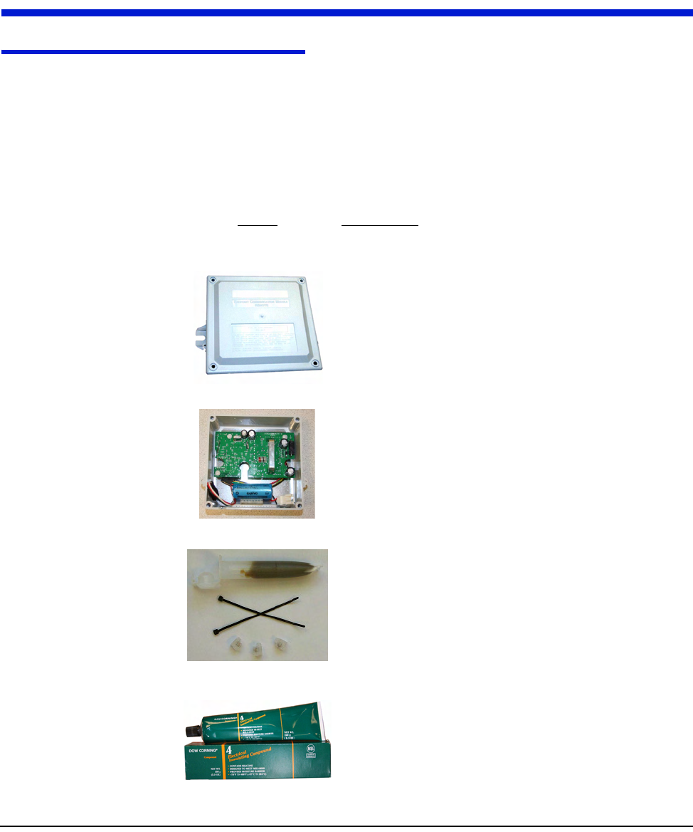
oc=_ìëíÉê=j~ÖåÉí
éLå=OSJNMRM
pÅêÉïÇêáîÉêë=EÑä~í=~åÇ=mÜáääáéëF
táêÉ=`ìííÉê=~åÇ=píêáééÉê
pÅçíÅÜäçâ®=bJVv=`êáãéáåÖ=qççä=çê=bèìáî~äÉåí
ïïïKPjKÅçã
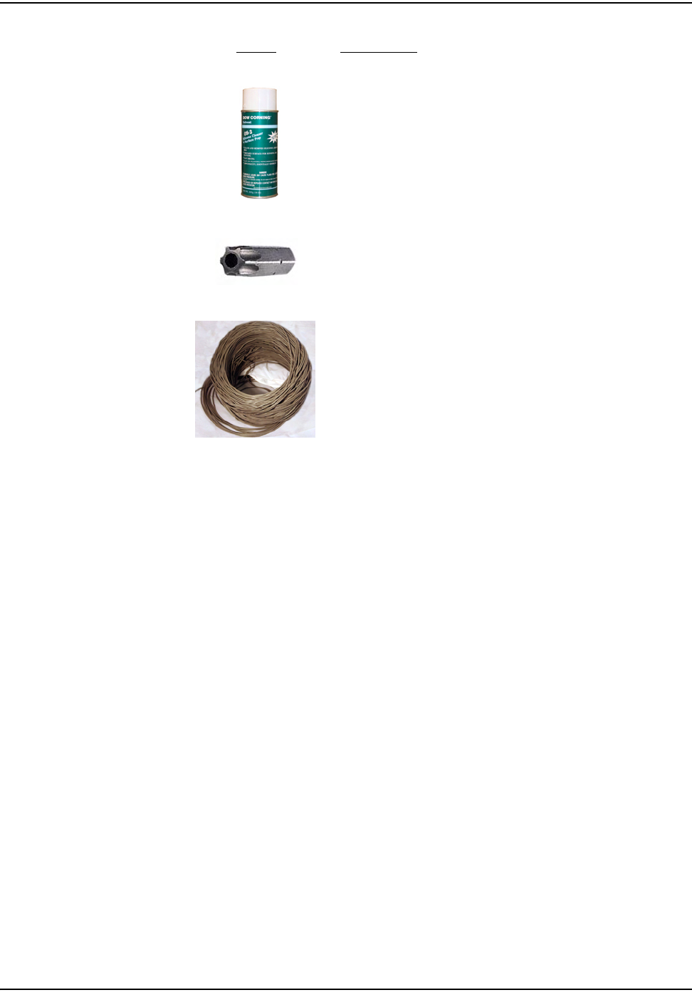
p~ÑÉíó=dçÖÖäÉë
e~åÇeÉäÇ=`çãéìíÉê=
ïïïKÇ~éKÅçã
NJt~ó=jçÇìäÉ=mêçÖê~ããáåÖ=`~ÄäÉ
j~ÖåÉí=
äçÅ~í ÉÇ=çå=
íçé =ä ÉÑí

`ÉääåÉí=mìäëÉ=oÉÅçêÇÉê=jÉíÉê=jçÇìäÉ=fåëí~ää~íáçå
TJQ `ÉääåÉí=d~ë=jçÇìäÉ=~åÇ=jÉíÉê=fåëí~ää~íáçå=dìáÇÉ
SAFETY AND ENVIRONMENT
Prerequisite Training
Installersshouldbeinstructedinthefollowingsafetyelementsaswellasanysite‐
specificsafetyissues:
• HazardCommunication(EmployeeRighttoKnow)
•Lifting
•Safedriving
•Useofhandtools
• Confinedspace
Preliminary Checks
TheinstallershouldalreadybeabletooperatetheHandHeldcomputer.
Additionally,theinstallershouldalreadyhaverouteinformationandthe
requirednumberofendpoints.
•Verifythatyouareatthecorrectsite,specifiedonthehandheldcomputeror
workorder.
•Verifythatthesiteissafeforyouandyourequipment.
•Notifythecustomerofyourpresence.Tellthecustomerthatyoumusthave
accesstothemeter.Ifnecessary,havethecustomersigntheworkorder.
•Wheninstallingmeters,followanyguidelinesissuedbyyourcompanyin
additiontothosegiveninthisguide.
• Neverperformaninstallationduringalightningstormorunderexcessively
wetconditions.
Site Requirements
Thesitemustcomplywiththefollowingcriteria:
•Thereisnochancethatanotherobjectwillbesetovertheantenna.
•Someinstancesmayrequireadditionalcable.
•Maximumcablelengthisalways200feet.
`ÉääåÉí=mìäëÉ=oÉÅçêÇÉê=jÉíÉê=jçÇìäÉ=fåëí~ää~íáçå
`ÉääåÉí=d~ë=jçÇìäÉ=~åÇ=jÉíÉê=fåëí~ää~íáçå=dìáÇÉ TJR
FCC INFORMATION
SeeAppendix F,CPRInformation,formoreinformation.
INSTALLING THE CELLNET PULSE RECORDER
ThefollowingincludesinformationaboutinstallingtheCPRendpoint.
Mounting the CPR
TheCPRendpointshouldbemountedaboveground,outdoors,facingthenearest
concentrator.
Identifying the Register for Installation
RefertotheGasModuleCompatibilityChartforcompatibilityandspecificparts
needed.
Connecting the PRECO Switch to the CPR
1InstallthePRECOswitchonthegasmeterindexaccordingtotheinstructions
includedwiththePRECOkit.
2RoutethecablefromthePRECOswitchtotheCPRmountinglocation.Splice
theadditionalcableasnecessary.Whenusingadditionalcable,alwaysmatch
colors:PRECObluetoCPRwhite(viagreenextensionwire),PRECOredto
CPRred,PRECOwhitetoCPRblack(viablackextensionwire).
3Ifyouneedtoaddcableforaremotewall‐mountedCPR,followthe
instructionshereforremovingtheMolexconnectors(ifpresent)andsplicing
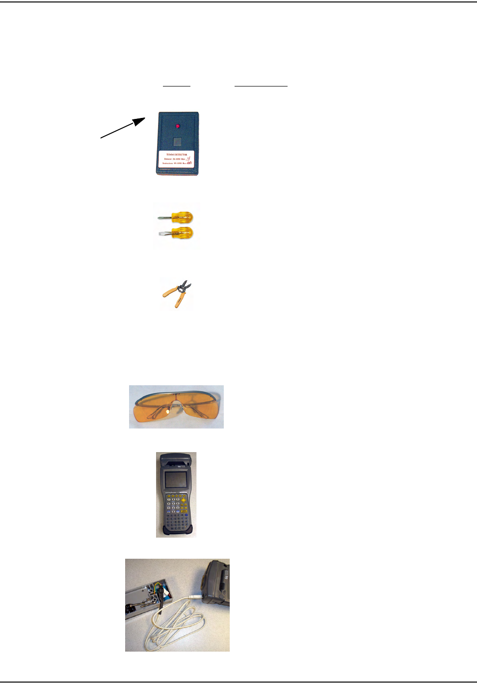
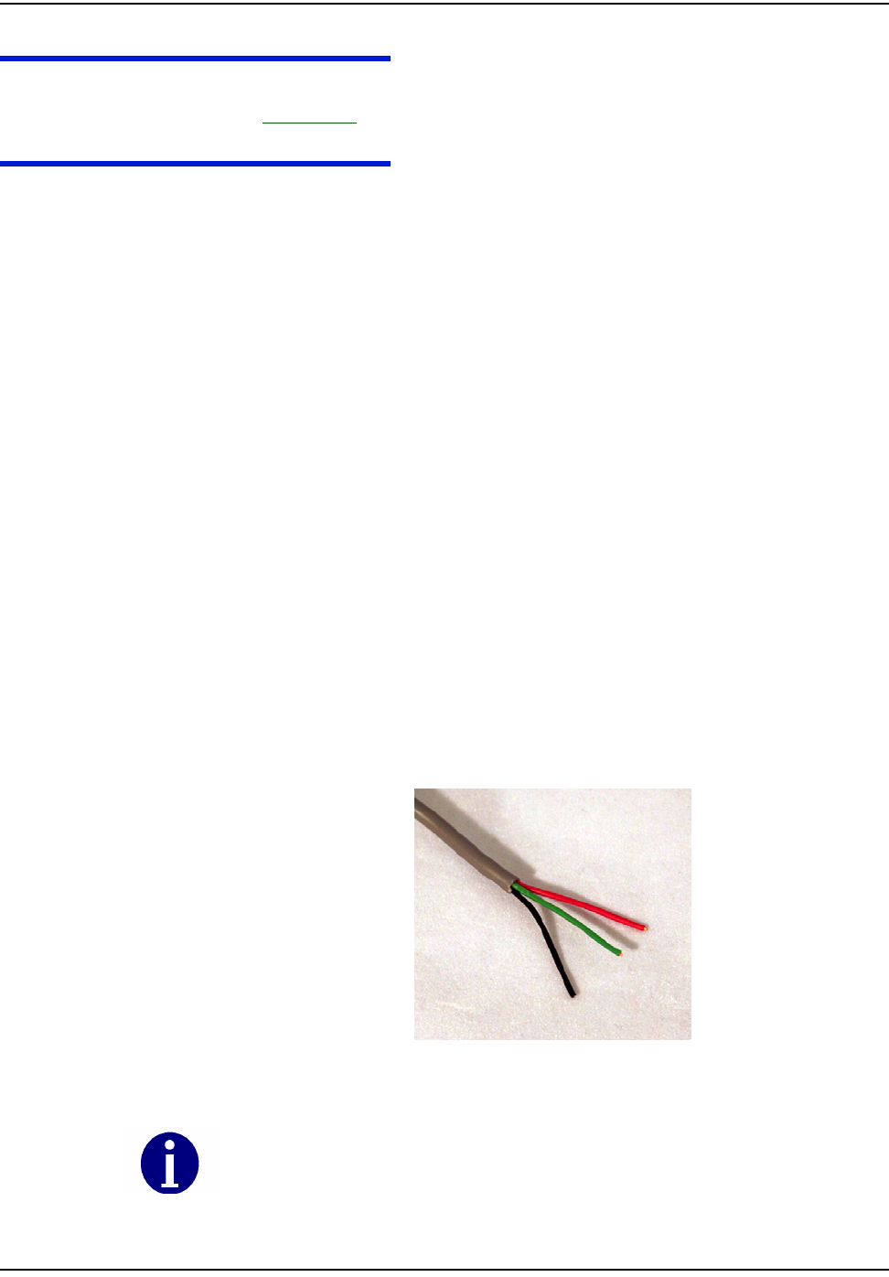
additionalcable.Preparecableendsforcrimping:
aUsingthecuttingbladeportionoftheWireCutterandStrippertool,cut
thewireattheMolexconnector(ifpresent)comingfromthePRECO
switch.ThewireattachedtothePRECOswitchcontainsthreewires.
Figure 7.1 3-Wire Cable
Do not damage internal wire insulation when removing external insulation.
`ÉääåÉí=mìäëÉ=oÉÅçêÇÉê=jÉíÉê=jçÇìäÉ=fåëí~ää~íáçå
TJS `ÉääåÉí=d~ë=jçÇìäÉ=~åÇ=jÉíÉê=fåëí~ää~íáçå=dìáÇÉ
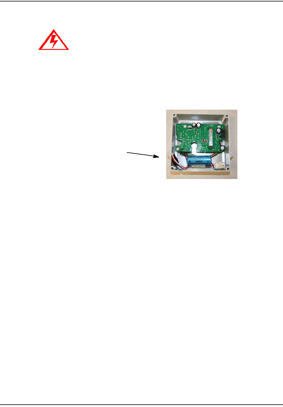
bBeforeproceedingwithsplicing,usetheWireCutterandStrippertocut
theMolexconnectoroffoftheCPRPulseInputConnector(identifiedby
whitewire).
Figure 7.2 Molex Connector (as shipped)
cSplicewiresfromCPRtoPRECOswitch.Matchcolorscarefully,
accordingtothetablebelow.
CPR ships with a female Molex connector at the loose end of the communication
cable.
CPR Pu lse Inpu t Conn ector
with white wire
`ÉääåÉí=mìäëÉ=oÉÅçêÇÉê=jÉíÉê=jçÇìäÉ=fåëí~ää~íáçå
`ÉääåÉí=d~ë=jçÇìäÉ=~åÇ=jÉíÉê=fåëí~ää~íáçå=dìáÇÉ TJT
Table7.3WireColorMatching
4SeeAppendix A:CrimpingWires,forinstructionsoncrimpingwires.
Programming CPR Endpoint for Operation with PRECO Switch
YoumustprogramtheCPRwiththeHandHeldcomputer(the“HandHeld”).
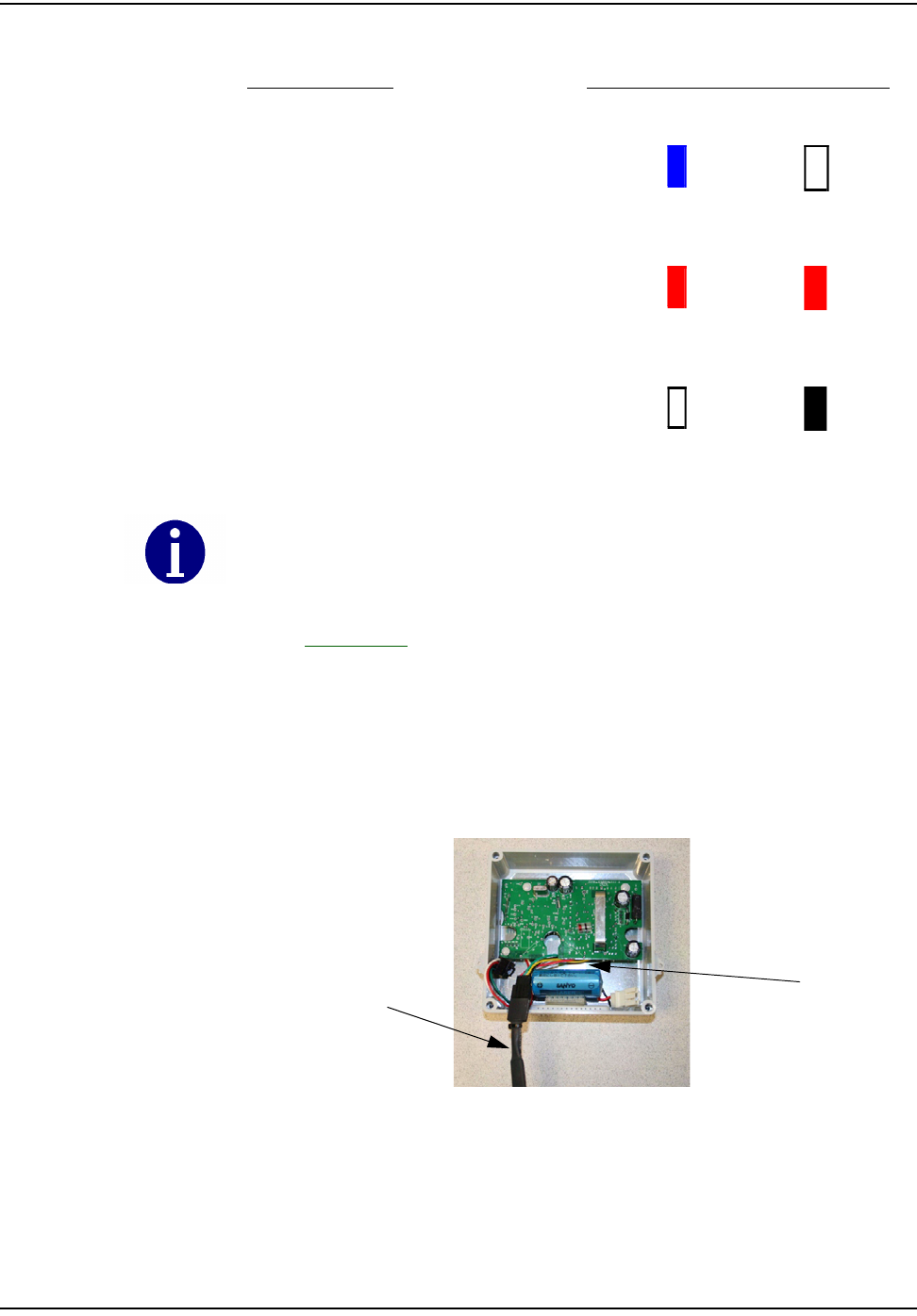
1 ConnecttheCPRProgrammingCabletotheCPRSerial/PowerConenctor
(yellowwire)below.
Figure 7.3 CPR Programming Cable Attached
2FollowtheHandHeldpromptstoprogramtheendpoint.
3Whenprogrammingiscomplete,disconnecttheprogrammingcablefromthe
CPR.
EncoderRegister PRECOWirecolor/CPRWireColor
PRECObluetogreenextensionto
CPRwhite
PRECOredtoredextensiontoCPR
red
PRECOwhitetoblackextensionto
CPRblack
blue white
red red
white black
Connect only three wires using the color matching above.
ProgrammingCable
CPRSerial/Power
Connector
`ÉääåÉí=mìäëÉ=oÉÅçêÇÉê=jÉíÉê=jçÇìäÉ=fåëí~ää~íáçå
TJU `ÉääåÉí=d~ë=jçÇìäÉ=~åÇ=jÉíÉê=fåëí~ää~íáçå=dìáÇÉ
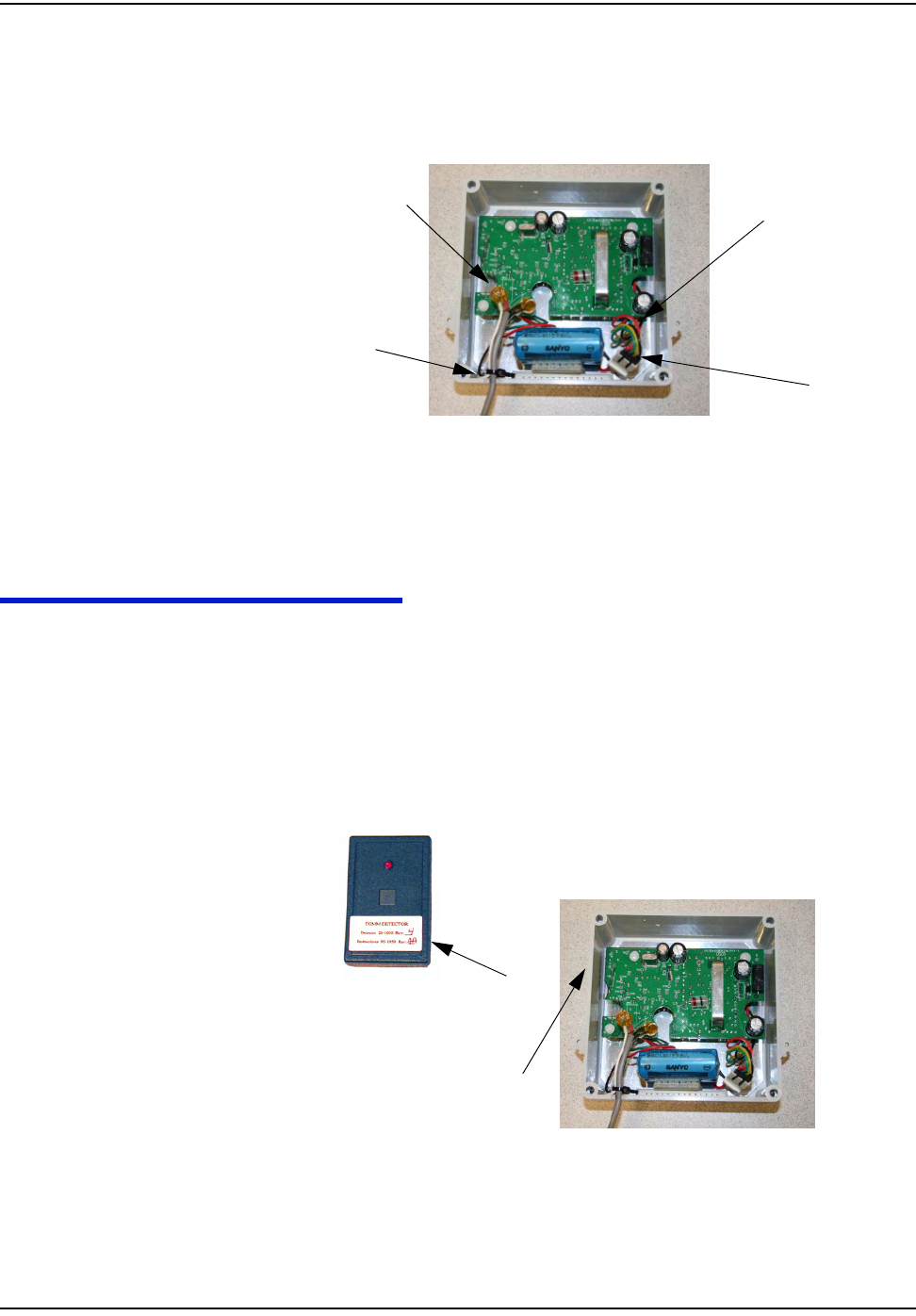
4 ConnectthebatterytotheCPR.
5DressthewiresandcrimpinsidetheCPRenclosureasshown.
Figure 7.4 CPR Battery Connector Connected to CPR
ProceedtoʺTestingtheEndpointʺonpage 7‐8.
TESTING THE ENDPOINT
Afteryouhavecompletedtheinstallationprocess,testtheinstallationbypassing
anRFBustermagnetneartheCPR’ssensor.TheRFBusterdetectsthe
transmission,beepsandlightstheLED.
1 ActivatetheCPRbypassingtheRFBustermagnetagainstthesideoftheCPR
housingasshown.
Figure 7.5 CPR Activation Using RF Buster
CrimpedWires
TieWrap
CPRSerial/Power
Connector
BatteryConnector
oc=_ìëíÉê=j~ÖåÉí
eçäÇ=íÜÉ=oc=_ìëíÉê=
ã~ÖåÉí=~Ö~áåëí=íÜáë=
ëáÇÉ=çÑ=íÜÉ=`mo

`ÉääåÉí=mìäëÉ=oÉÅçêÇÉê=jÉíÉê=jçÇìäÉ=fåëí~ää~íáçå
`ÉääåÉí=d~ë=jçÇìäÉ=~åÇ=jÉíÉê=fåëí~ää~íáçå=dìáÇÉ TJV
2PressandholdthebuttonontheRFBuster.PositiontheRFBusterlessthan
sixinchesawayfromtheleftsideoftheCPR.TheRFBustermakesaudible
beepsandtheLEDflashestoconfirmtransmissionoftheRFpacketsfromthe
endpoint.
3IftheRFBusterdetectspacketswithinoneminute,theinstallationisgood.If
theRFBusterdoesnotbeep,refertoʺTroubleshootingʺonpage 7‐9.
4 Attachthecoverusingthefourscrewsincludedinthehardwarekit.
5Cleantheareaandremovealldisposablematerials.
ENDPOINT REPLACEMENT
Pleasefollowtheinstructionsbelowtoreplaceanendpoint:
1OpenthefaceoftheCPR.
2Writedownthecolortranslation.
3Carefullycutanytiewraps.
4CutoffScotchloksnearthecrimp.
5 UnmounttheCPR.
6 Disconnectthebattery.
ProceedtoʺConnectingthePRECOSwitchtotheCPRʺonpage 7‐5.
TROUBLESHOOTING
RF Buster Does Not Beep When Testing
1First,verifythatthebatteryisproperlyconnected,redwiretoredwire.
2DoestheRFBusterbeepandlighttheLEDwhentheswitchisinitially
pressed?Ifnot,thebatteryintheRFBusterisdead.ReplacetheRFBuster
battery,oruseanotherRFBuster.
3AfteractivatingthemagneticswitchontheCPR,holdtheRFBusterswitch
oncontinuously.PointtheLEDendoftheRFBustertowardthefrontofthe
CPR.HoldtheRFBusterbetween6”and12”fromthefrontoftheCPR.Wait
tenseconds.IftheRFBusterdoesnotbeep,replacetheCPRbattery.
Customer Support
ToreachCustomerSupportatCellnet:
Email:customersupport@cellnet.com
Telephone:1‐800‐791‐2567.
Hoursofoperation‐8:00a.m.ETto5:00p.m.ET
Do not use a cell phone or any other RF device while conducting
this test.

`ÉääåÉí=mìäëÉ=oÉÅçêÇÉê=jÉíÉê=jçÇìäÉ=fåëí~ää~íáçå
TJNM `ÉääåÉí=d~ë=jçÇìäÉ=~åÇ=jÉíÉê=fåëí~ää~íáçå=dìáÇÉ

`ÉääåÉí=d~ë=jçÇìäÉ=~åÇ=jÉíÉê=fåëí~ää~íáçå=dìáÇÉ UJN
CHAPTER 8 METER EXCHANGE OR MODULE RETROFIT CONCLUSION
Priortoleavingthepremise,verifythatalldebrisfromtheretrofitand/or
exchangeprocessiscleanedandremoved.Leaveadoorhangertagwithany
appropriateinformationfilledin.
RETURNING MATERIAL
Attheendoftheday,installerswillreturntotheCrossDockwithallequipment
andanynewmetersormodulesthatwerenotinstalled.Eachinstallermust
accountforeverymetertheywereassigned.Turnininventoryofunused,
defective,orbrokengasMeterModules.Youmustreconcileanydiscrepanciesin
changeoutdatabeforethecheck‐inprocesscanbecompleted.Metersand
moduleswillnotbecheckedouttoaninstallerwhohasnotcompletedthe
previousdayʹscheck‐inprocess.

Notes:
UJO `ÉääåÉí=d~ë=jçÇìäÉ=~åÇ=jÉíÉê=fåëí~ää~íáçå=dìáÇÉ
jÉíÉê=bñÅÜ~åÖÉ=çê=jçÇìäÉ=oÉíêçÑáí=`çåÅäìëáçå

`ÉääåÉí=d~ë=jçÇìäÉ=~åÇ=jÉíÉê=fåëí~ää~íáçå=dìáÇÉ VJN
CHAPTER 9 GAS METER PREPARATION PROGRAM (GPREP)
TheGasMeterPreparationProgram(GPrep)isasoftwaretoolthatfacilitates
Cellnetprocesses.ItalsorunswithwaterCPRmodules.Thedatacapturedby
GPrepissenttoRIMStoupdatetheCellnetandutilitiesdatabases.GPrepwas
developedforResGas,C&IGas(Diaphragm),C&IGas(Rotary),andCPR(gas
andwater)modulesto:
• DisassociateModuleIDsfromMeterIDs‐“MRB(MaterialRepairBoard)
Mode”Thisfeaturemostcommonlycapturestherecordofdisassociation
whenremovingamodulefromthefield.
• ValidatetheprogrammedLANAddresswiththePowerLANAddresslabel
andverifythattheoperationalprogrammedparametersmatchthose
required.‐“InspectMode”.
Thisfeatureismostcommonlyusedwhenreceivingmetersfromthefactory
withCellnetmodulesalreadyinstalled(OEMMeters)orwhenreceiving
CellnetretrofitmodulesdirectlyfromCellnet’smanufacturer.Different
utilitiesusedifferentsamplingprocedures.Themetershopshouldverifya
percentageofinboundmodulestoensurethattheLANAddressthatis
programmedintothegasmoduleandmatchestheLANAddressonthelabel
outsideofthemodulehousing.Themodulescanalsobeinspectedtoverify
thatthecorrectMeterIDformatwasused,thattherolloverpointiscorrect,
andthatthemeterconstantiscorrect.
•P
rogramthemodulewithoperationalparameters,includingthemeter‐
specificvaluessuchasmeterID,rolloverpoint,meterconstant,anddial
indexreading(whichforgasmeterscanbenon‐zero)‐“ProgramNeworRe‐
ProgramOldMode”.
ThisfeatureisusedwhenassemblingCellnetmodulesonmetersinthemeter
shopandinthefield(fortheO&MProcesses).
•Savetheinspection,programming,MRBdisassociationrecordandindexread
resultsinseparatefilesfordeliverytoCellnetandtheutility.
Thiscanbeanautomaticprocessoryoucanturneditoffforaparticular
featurewhenitisnotnecessarytosavetheresults.
YoucanuseGPrepinametershop,atafixedlocation,orinthefield.Youcanuse
aPCorlaptopcomputer.CloselymonitorGPrepusage,andmakethedatafiles
easilyaccessible.GPrepisoftenusedwithoperationsandmaintenance(O&M)
Each of these functions are steps in Cellnet processes. You should fully understand how
data flows within the Cellnet network and what data needs to be captured from or
programmed into a module before using this software.

d~ë=jÉíÉê=mêÉé~ê~íáçå=mêçÖê~ã=EdmêÉéF
VJO `ÉääåÉí=d~ë=jçÇìäÉ=~åÇ=jÉíÉê=fåëí~ää~íáçå=dìáÇÉ
processes.ThischapterassumesthattheuserfullyunderstandstheseO&M
processes,andatwhichstepsintheseprocessesGPrepcapturesdataand
programsitintoCellnetmodules.
GPreprequiresselectivefunctionalitydependingonthesitewhereitisinuse,so
thereareadministrativeprivilegesforconfiguringoptionsduringsoftware
installationandsetup.

d~ë=jÉíÉê=mêÉé~ê~íáçå=mêçÖê~ã=EdmêÉéF
`ÉääåÉí=d~ë=jçÇìäÉ=~åÇ=jÉíÉê=fåëí~ää~íáçå=dìáÇÉ VJP
REQUIRED TOOLS
ThefollowingisalistofrequiredtoolstooperateGPrep,alongwithaPC/
operatingsystemrecommendation:
•DesktopPCwithWindows2000orhigher(WindowsNTisnot
recommendedwhenusingalaptopcomputersincetherearesometimes
problemsconfiguringtheports)
•CopyofGPrepv.2.3ormostrecentversiononarequiredtoolsCD
• ShooterBoxwithACpowercord,partnumber26‐3500andgasshootercable
or
1‐WayModuleProgrammingCablePN26‐1179
• Battery,partnumber40‐1032or40‐1590
•Laptop/PC
•DB9toDB9cable(maleononeendfemaleontheother)straightthrough
(RS232).
Roles
•GPrepAdministrator‐isthelocalexpertonGPrep.TheAdministratoris
familiarwiththeentirefunctionalityofGPrep.TheAdministratorknows
howtoconfigureallinternalfiles,andhowtograntcertainpermissions.
TheAdministratorknowshowtocleanallfilesofbadrecordsand
supersedes.Howtoarchiveallfilesande‐mailthemtotheappropriate
databaseadministratororRIMSanalystandhowtotrainthedaytodayusers
ofGPrep.ThispersonhasthedailytaskofmaintainingGPrepanditsfiles.
•GPrepUser‐needstoknowthefundamentalsofGPrep.Theyneedtoknow
howtologin,howtomarryameterwithamodule,andhowtoinspecta
moduletoensurethatitisproperlyprogrammed,andwhattodoifitisnot.
PROCEDURES FOR GPREP ADMINISTRATOR
1Verifyyourtools.GPrepdoesnotoperatewithoutallofthetoolslistedinthe
RequiredToolssection.
2UnzipGPrepfilestoyourPCorlaptop.
aCustomizeGPrep.
TheGPrepinstallationfoldercontainsafilenamedGPREP.INI.Thisfile
definesallconfigurationparametersinits[Control]sectionand
maintainssettingsfromthelastGPrepruninits[Default]section.
•Ifthisisanewinstallation,GPREP.INImustbecopiedtotheGPrep
installationdirectory.
Before copying files go to “View” on the menu bar of your PC, select “Folder
Options”. Under a section titled “Advanced Settings” there is a folder called
“Hidden files”, under that folder choose “show all files”, then click on the OK
button.

d~ë=jÉíÉê=mêÉé~ê~íáçå=mêçÖê~ã=EdmêÉéF
VJQ `ÉääåÉí=d~ë=jçÇìäÉ=~åÇ=jÉíÉê=fåëí~ää~íáçå=dìáÇÉ
•Ifthisisanupgrade,thenyoucanusetheexistingGPREP.INIfileto
modifyanyconfigurationparametersasnecessary.
bEdittheGPREP.INIfileusingNotepadoranyotherASCIIfileeditor.
cFollowtheinstructionsinthatfiletospecifytherequiredpatternfor
MeterIDs,file(s)forloggingoperations,menuselectionsthatare
availabletotheoperatorandthemaximummemoryusedtotrack
previouslogfileassociations.
FollowingisanexampleofaGPREP.INIfile.
; The Default section remembers GPrep settings from the last run. These
should
; not be changed manually.
; -------------------------------------------------------------------------
-----
[Default]
; The Control section contains GPrep operational parameters.
; -------------------------------------------------------------------------
-----
; Operator Meter Type selections are controled by variables:
;
; RGAS for ResGas
; CIGD for C&I Gas (Diaphragm)
; CIGR for C&I Gas (Rotary)
; CPRG for CPR Gas (Rotary)
;
; Setting any of these to "No" disables the menu item. The default is
"Yes".
;
; Example:
; RGAS=No
; CIGR=Yes
; Disables "ResGas" selection, leaving both C&I and CPR selections enabled.
; -------------------------------------------------------------------------
-----
; Operator Mode selections are controled by variables:
;
; Inspect
; ProgramNew
; ProgramOld
; IndexRead
; MRBMode
;
; Setting any of these to "No" disables the menu item. The default is
"Yes".
;
; Example:
; ProgramOld=No
; Inspect=Yes
; MRBMode=No
If you run GPrep in different modes and/or it requires different configuration settings at the
same operator station, then install multiple copies of GPrep in different directories.

d~ë=jÉíÉê=mêÉé~ê~íáçå=mêçÖê~ã=EdmêÉéF
`ÉääåÉí=d~ë=jçÇìäÉ=~åÇ=jÉíÉê=fåëí~ää~íáçå=dìáÇÉ VJR
; Disables "Re-Program Old" and "MRB" selections, leaving "Inspect",
; "Program New" and "Index Read" modes enabled.
; -------------------------------------------------------------------------
-----
; Operator Port selections are controled by variables:
;
; COM1, COM2, COM3 and COM4
;
; Setting any of these to "No" disables the menu item. The default is
"Yes".
;
; Example:
; COM4=No
; COM3=No
; COM1=Yes
; Disables "COM3" and "COM4" selections, leaving "COM1" and "COM2" enabled.
; -------------------------------------------------------------------------
-----
; MeterID is a pattern string for scanned (or entered) Meter IDs. The
length
; of the pattern gives the number of characters required and each character
; in the pattern corresponds to a character in the Meter ID; if it's:
;
; # - The character must be a decimal digit (0 - 9)
; $ - The character must be alphabetic (A - Z)
; _ - The character must be a blank
; ? - The character may be anything
; All other characters must match exactly.
;
; Note: If MeterID is not given then no pattern matching is done.
;
; Examples:
; MeterID=ABC### - IDs must must be 6 characters long, and start with
; "ABC" followed by 3 digits
; MeterID=Q???##_$$### - IDs must be 12 characters long, start with a "Q",
; followed by any 3 characters, then 2 digits, a
space,
; 2 alphabetic characters, and end with 3 digits.
; MeterID=- IDs are not checked against a prototype, only for
; valid characters.
; -------------------------------------------------------------------------
-----
; ProgramLog is the full path and file name for logging each time a module
is
; programmed. If not given, then no program log file is written.
;
; Examples:
;
; ProgramLog=c:\gprep\program.txt - program.txt in the gprep directory on
drive C:
; ProgramLog=program.txt - program.txt in the GPrep program
directory
; ProgramLog=program - program.txt in the GPrep program
directory
; ProgramLog=- Do not write a program log file
; -------------------------------------------------------------------------
-----
; InspectLog is the full path and file name for logging each time a module
is
; inspected. If not given, then no inspection log file is written.

d~ë=jÉíÉê=mêÉé~ê~íáçå=mêçÖê~ã=EdmêÉéF
VJS `ÉääåÉí=d~ë=jçÇìäÉ=~åÇ=jÉíÉê=fåëí~ää~íáçå=dìáÇÉ
;
; Examples:
;
; InspectLog=c:\gprep\inspect.txt - inspect.txt in the gprep directory on
drive C:
; InspectLog=inspect.txt - inspect.txt in the GPrep program
directory
; InspectLog=inspect - inspect.txt in the GPrep program
directory
; InspectLog=- Do not write an inspection log file
; -------------------------------------------------------------------------
-----
; MRBLog is the full path and file name for logging each time a module is
; inspected in MRB Mode. If not given, then no MRB log file is written.
;
; Examples:
;
; MRBLog=c:\gprep\mrblog.txt - mrblog.txt in the gprep directory on drive C:
; MRBLog=mrblog.txt - mrblog.txt in the GPrep program directory
; MRBLog=mrblog - mrblog.txt in the GPrep program directory
; MRBLog=- Do not write an MRB log file
; -------------------------------------------------------------------------
-----
; ReadLog is the full path and file name for logging each time a module is
; inspected in Index Read Mode. If not given, then no read log file is
written.
;
; Examples:
;
; ReadLog=c:\gprep\readdlog.txt - readdlog.txt in the gprep directory on
drive C:
; ReadLog=readdlog.txt - readdlog.txt in the GPrep program
directory
; ReadLog=readdlog - readdlog.txt in the GPrep program directory
; ReadLog=- Do not write an inspection log file
; -------------------------------------------------------------------------
-----
; MaxAssociations is the maximum number of LANAddress / Meter ID
associations
; checked from the log file to assure that duplications are not assigned.
; This requires 24 bytes of memory per association. Set to 0 to disable.
;
; Examples:
;
; MaxAssociations=1000 - Previous 1000 records are checked (memory =
24,000)
; MaxAssociations=10000 - Previous 10000 records are checked (memory =
240,000)
; MaxAssociations=0 - Disables duplication association checking.
; -------------------------------------------------------------------------
-----
Mode=ReProgram
ModuleClass=1
RolloverPoint1=1000000
MeterConstant1=0.050000
SerialPort=1
Operator=Bill
Location=xdcsu
Utility=SCG
RolloverPoint0=10000

d~ë=jÉíÉê=mêÉé~ê~íáçå=mêçÖê~ã=EdmêÉéF
`ÉääåÉí=d~ë=jçÇìäÉ=~åÇ=jÉíÉê=fåëí~ää~íáçå=dìáÇÉ VJT
MeterConstant0=0.020000
RolloverPoint3=100000
MeterConstant3=1.000000
RolloverPoint2=100000
MeterConstant2=0.100000
MeterConstant4=0.250000
ProgramMode=Yes
ProgramDial=Yes
RolloverPoint=100000
MeterConstant=1.000000
LastFile=WCPR.SET
[Control]
meterID=?????????
DeviceID=?????
RGAS=yes
CIGD=yes
CIGR=yes
CPRANT=yes
CPRAWT=yes
CPRCWT=yes
WCPR=yes
Inspect=yes
ProgramNew=yes
ProgramOld=yes
MRBMode=yes
IndexRead=N
ProgramLog=c:\programlog.txt
inspectLog=c:\inspectlog.txt
MRBLog=c:\MRBlog.txt
ReadLog=c:\readlog.txt
wProgramLog=c:\wprogramlog.txt
winspectLog=c:\winspectlog.txt
wMRBLog=c:\wMRBlog.txt
[RGAS]
MeterConstantCount=4
MeterConstant1=.01
MeterConstant2=.0112
MeterConstant3=.02
MeterConstant4=.0225
RollOverPointCount=5
RollOverPoint1=100
RollOverPoint2=1,000
RollOverPoint3=10,000
RollOverPoint4=100,000
RollOverPoint5=100000000
[CPRAWT]
MeterConstantCount=9
MeterConstant1=.01
MeterConstant2=.01121
MeterConstant3=.02
MeterConstant4=.0225
MeterConstant5=.05
MeterConstant6=.0562
MeterConstant7=.1

d~ë=jÉíÉê=mêÉé~ê~íáçå=mêçÖê~ã=EdmêÉéF
VJU `ÉääåÉí=d~ë=jçÇìäÉ=~åÇ=jÉíÉê=fåëí~ää~íáçå=dìáÇÉ
MeterConstant8=.112
MeterConstant9=1.0
RollOverPointCount=6
RollOverPoint1=100
RollOverPoint2=1,000
RollOverPoint3=10,000
RollOverPoint4=100,000
RollOverPoint5=100,00000
RollOverPoint6=100,000000
[CPRANT]
MeterConstantCount=10
MeterConstant1=.01
MeterConstant2=.01121
MeterConstant3=.02
MeterConstant4=.0225
MeterConstant5=.05
MeterConstant6=.0562
MeterConstant7=.1
MeterConstant8=.112
MeterConstant9=1.0
MeterConstant10=2.0
RollOverPointCount=5
RollOverPoint1=100
RollOverPoint2=1,000
RollOverPoint3=10,000
RollOverPoint4=100,000
RollOverPoint5=100,000,000
[CPRCWT]
MeterConstantCount=9
MeterConstant1=.01
MeterConstant2=.01121
MeterConstant3=.02
MeterConstant4=.0225
MeterConstant5=.05
MeterConstant6=.0562
MeterConstant7=.1
MeterConstant8=.112
MeterConstant9=1.0
RollOverPointCount=5
RollOverPoint1=100
RollOverPoint2=1,000
RollOverPoint3=10,000
RollOverPoint4=100,000
RollOverPoint5=99999999
[CIGR]
MeterConstantCount=5
MeterConstant1=.05
MeterConstant2=.0562
MeterConstant3=.1
MeterConstant4=.112
MeterConstant5=1.0
RollOverPointCount=5
RollOverPoint1=100
RollOverPoint2=1,000
RollOverPoint3=10,000
RollOverPoint4=100,000

d~ë=jÉíÉê=mêÉé~ê~íáçå=mêçÖê~ã=EdmêÉéF
`ÉääåÉí=d~ë=jçÇìäÉ=~åÇ=jÉíÉê=fåëí~ää~íáçå=dìáÇÉ VJV
RollOverPoint5=100,0000
[CIGD]
MeterConstantCount=5
MeterConstant1=.05
MeterConstant2=.0562
MeterConstant3=.1
MeterConstant4=.112
MeterConstant5=1.0
RollOverPointCount=5
RollOverPoint1=100
RollOverPoint2=1,000
RollOverPoint3=10,000
RollOverPoint4=100,000
RollOverPoint5=100,0000
[WCPR]
MeterConstantCount=1
MeterConstant1=1
RollOverPointCount=5
RollOverPoint1=100
RollOverPoint2=1,000
RollOverPoint3=10,000
RollOverPoint4=100,000
RollOverPoint5=100,0000
SaveyourupdatestotheGPrep.inifile.GPrepisreadytouse.
DATA TRANSFER
AlocalRIMSanalystperformsthisprocess.TheRIMSAnalystuploadsMRBand
ProgramfilestotheserverviaFTP.
Server Side Process
ThepersonusingGPrep,orthelocaladministrator,poststheprogramlogand
MRBfilestoCellnetʹsFTPServer.YoucanuseanySFTPTooltopostfilesfrom
gasandwaterprocesses.TheGPREP.inifiledeterminesthenameandpathofthe
filesgeneratedinthelocalmachine.EachUtilityshoplocationcanpostmultiple
files,aslongaseachfileisuniquelyidentified.Thelocalsitecanuseanylogicto
namethesefiles,preferablytoincludedateandtime.
Oncethesefilesareposted,theDESservervalidatesfileformatandcleanup
activitiesbyeliminatingduplicateentriesandstoringtheprogramlogsandMRB
datainstagingtables.Theserveremailssubscribersfromsourcelocation.RIMS
CRONrunsnightly,processingmetersandupdatingthelatestassociationsto
OCDB.
d~ë=jÉíÉê=mêÉé~ê~íáçå=mêçÖê~ã=EdmêÉéF
VJNM `ÉääåÉí=d~ë=jçÇìäÉ=~åÇ=jÉíÉê=fåëí~ää~íáçå=dìáÇÉ
USING GPREP
ThissectiondetailsthestepstakenbytheendusertooperateGPreponadaily
basis.Thissetofproceduresassumesthefollowing:
•YourGPrepadministratorhasconfiguredthe.inifile.
•Youhavebasicknowledgeoftheprocessthatyouaretryingtoperformand
understandatwhichstepoftheprocessyouneedtouseGPrep.
• Shooterboxor1‐wayprogrammingcable
Ifyouareusingtheprogrammingcable(usuallyinthefield):
1Installdriversandsetupthecableperinstructionsinthe1‐WayModule
ProgrammingCableGettingStartedGuide.
2Plugoneendofthecableintothemodule.
3PlugtheUSBintothelaptoporPC.
Figure 9.1 1-Way Programming Cable
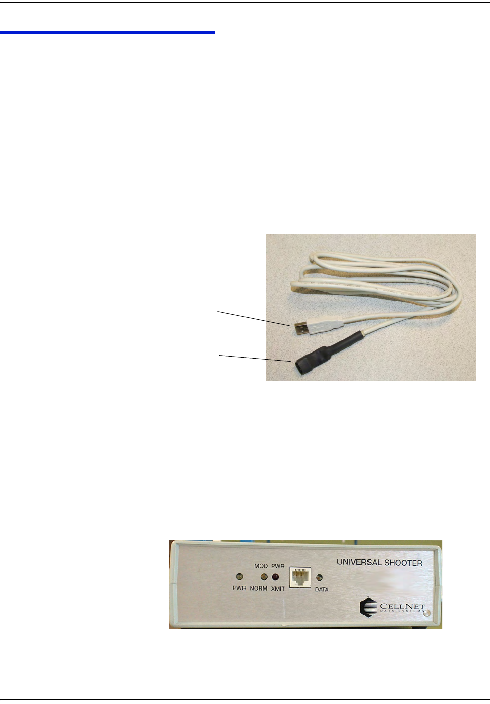
Ifyouareusingtheshooterbox(usuallyintheofficeorshop):
1Plugthebatteryintotheshootercable.
2Powertheshooterbox.
3 ConnecttheshooterboxtoaCOMportonyourPC,andchoosethecorrect
COMportfromthedropdownmenuonGPrep(oritdefaultstothatport).
4Pl
ugtheshootercableintotheshooterboxandthemodule.
Figure 9.2 Shooter box
USB Connector
Module Connector
d~ë=jÉíÉê=mêÉé~ê~íáçå=mêçÖê~ã=EdmêÉéF
`ÉääåÉí=d~ë=jçÇìäÉ=~åÇ=jÉíÉê=fåëí~ää~íáçå=dìáÇÉ VJNN
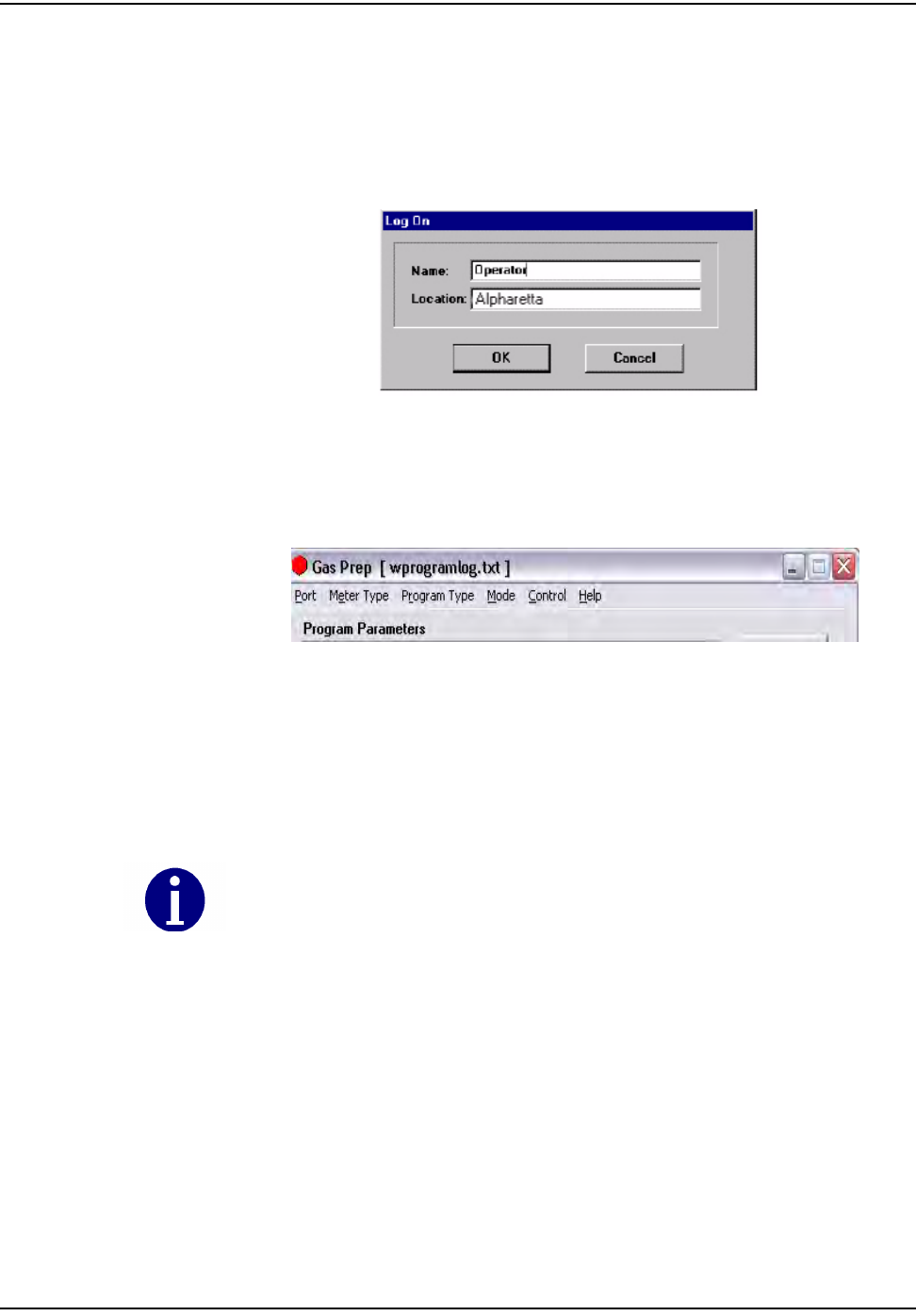
Logging On
TheLogOnwindowdisplayswhenyoulaunchtheprogram.
Enteryournameandlocationintheappropriatefields.Alltasksyouperformfor
agivenmetertype(moduleinspection,newmoduleprogrammingandold
modulereprogramming,MRBandindexread)willberecorded.
Figure 9.3 Log On screen
Accessing the Main Menu
Themainmenuscreendisplaysafteryoulogon.
Figure 9.4 GPrep Menu Bar
TheGPrepmenubarincludesthefollowingoptions:
Port:enablestheoperatortoselectthePCport(usuallyCOM:1).
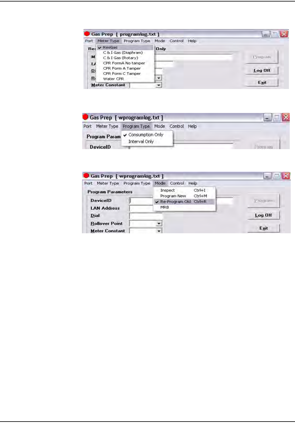
Metertype:Enablestheoperatortoselectmetertypefromdropdownlist.The
optionsconsistofResGas,C&IGas(Diaphragm),C&I(Rotary),CPRFormANo
Tamper,CPRFormBTamper,CPRFormCTamper,andCPRWater.
ProgramType:SelectIntervalorConsumptiontypedata.
Mode:providesthefollowingchoices:
Certain sites may not utilize all options.

d~ë=jÉíÉê=mêÉé~ê~íáçå=mêçÖê~ã=EdmêÉéF
VJNO `ÉääåÉí=d~ë=jçÇìäÉ=~åÇ=jÉíÉê=fåëí~ää~íáçå=dìáÇÉ
•Inspect:VerifiesthattheprogrammedLANAddresshasthesamevalueas
thePowerLANAddresslabel.Inaddition,“Inspect”permitsvalidatingthe
otherpre‐configuredoperationalparameters.Discrepanciesarenoted
throughmessagewindowsandtheresultsofinspectionsarecapturedin
associatedfiles.
•ProgramNew:providesthecapabilitytoprogramanewmeterforaspecified
rolloverpointandameterconstantforaspecificutilitymeterIDformat.
•Re‐ProgramOld:providesthecapabilitytoprogramameterwithanon‐zero
index.Thisoptionwasdesignedforutilitymetershopstoreprogrammeter‐
modulespulledfromthefieldorprogramanon‐zeroindexread.Allother
featuresforthisoptionaresimilartotheProgramNewmode.The
“programlog.txt”filealsoincludestheindexreadenteredduringthe
programmingstepasthefield“openingread”.
•MRB:capturesthedisassociationrecordformetersreturnedfromthefield.
ThisoptionismainlydesignedformetershopuseduringtheO&Mphase.
Thefollowingscreensshowhowtheoperatorhastheoptionofchoosinginspect,
programnew,andindexreadwhenResGasischosenastheMeterType.
The unique meter ID format for a given utility is defined in the “.ini” file. Any
discrepancy in the meter ID format is noted in a message window, which
prompts the operator to re-enter the meter ID prior to module programming. The
association record of meter ID, module LAN Address, date, operator’s name, and
result of operation is captured in the file “programlog.txt”.
d~ë=jÉíÉê=mêÉé~ê~íáçå=mêçÖê~ã=EdmêÉéF
`ÉääåÉí=d~ë=jçÇìäÉ=~åÇ=jÉíÉê=fåëí~ää~íáçå=dìáÇÉ VJNP
Figure 9.5 Choose ResGas as the meter type
Figure 9.6 Indicate the Program Type
Figure 9.7 Modes to choose from are “Inspect” or “Program New”
•Control:providesthecapabilitytologonandoff.Theprogramsetting
remainsthesamewhenanewoperatorlogson.
•Help:providesadescriptionofGPrepfunctionalityforeachmodeof
operation(notyetfullyimplemented).
d~ë=jÉíÉê=mêÉé~ê~íáçå=mêçÖê~ã=EdmêÉéF
VJNQ `ÉääåÉí=d~ë=jçÇìäÉ=~åÇ=jÉíÉê=fåëí~ää~íáçå=dìáÇÉ
MODULE INSPECTION
Thisfeatureismostcommonlyusedwhenreceivingmetersfromthefactorywith
Cellnetmodulesalreadyinstalled(OEMMeters)orwhenreceivingCellnet
modulesfromCellnet’smanufacturer.Differentutilitiesusedifferentsampling
procedures.Cellnetrecommendsthatthemetershopverifyapercentageof
inboundmodulestoensurethattheLANAddressthatisprogrammedintothe
modulematchestheLANAddressontheoutsideofthemodulehousing.The
modulescanalsobeinspectedtoverifythatthecorrectMeterIDformatwas
used,thattherolloverpointiscorrect,andthatthemeterconstantiscorrect.
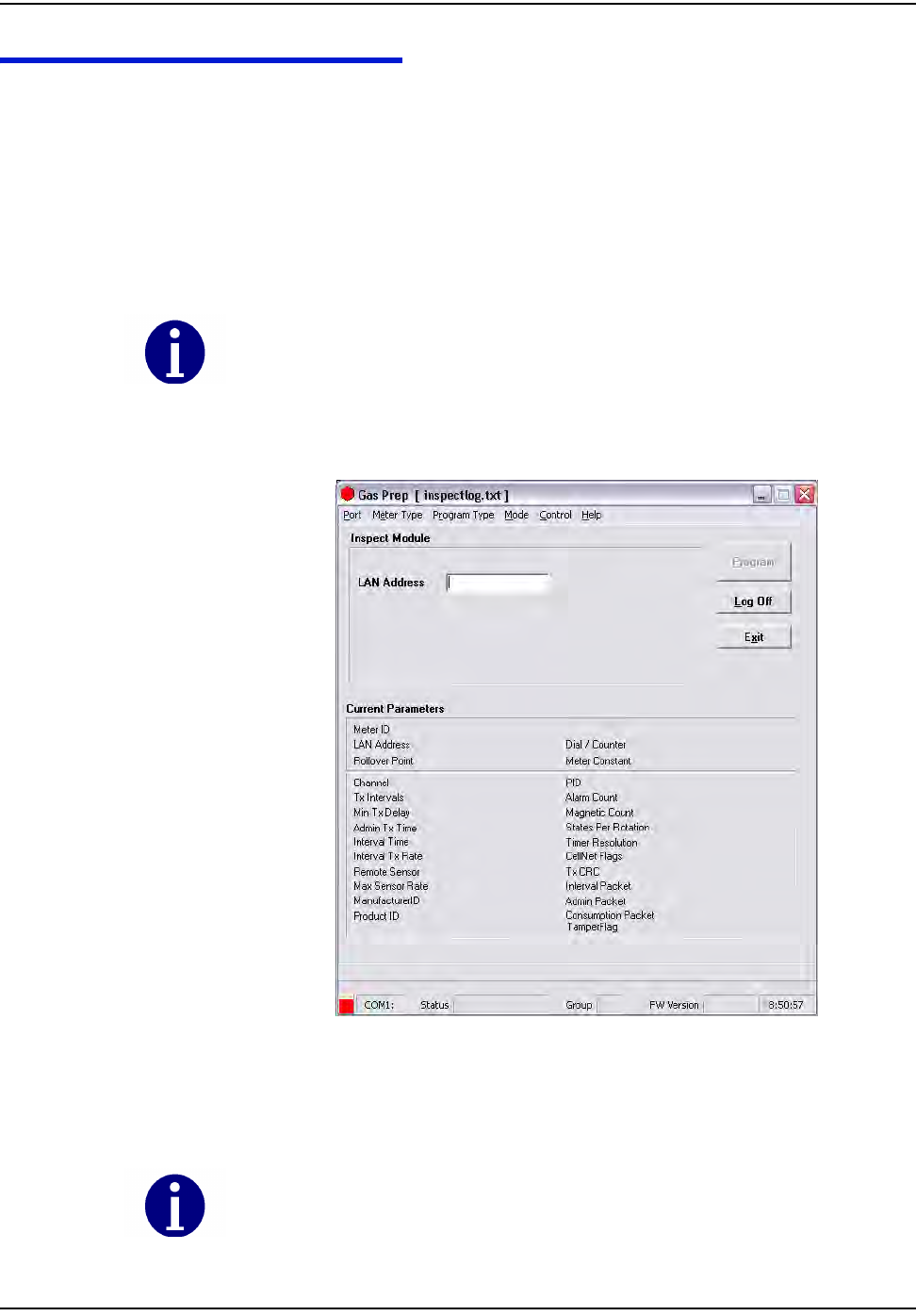
1SelectInspectfromtheModedropdownwindowinthemainmenu.The
followingscreendisplays.
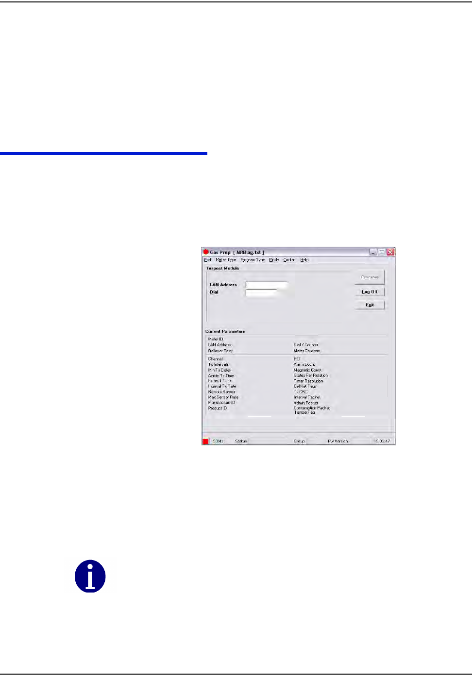
Figure 9.8 GPrep “Inspect Mode” screen
Therearetwodistinctsectionsonthescreen.ThetopsectionistheLANAddress
fieldwherethemodulepowerLANlabeliseitherscannedortyped.
Different modes of operation for ResGas modules are provided in detail. All other meter/
module types follows the identical functionality and operations, except as noted for Water
CPR.
The program automatically truncates the leading zeros and any blank spaces in the LAN
Address field. GPrep left justifies the value in this field.
d~ë=jÉíÉê=mêÉé~ê~íáçå=mêçÖê~ã=EdmêÉéF
`ÉääåÉí=d~ë=jçÇìäÉ=~åÇ=jÉíÉê=fåëí~ää~íáçå=dìáÇÉ VJNR
Thelowersection,“currentparameters”,displaystheoperationalparameters
andmoduleprogrammedvalues.
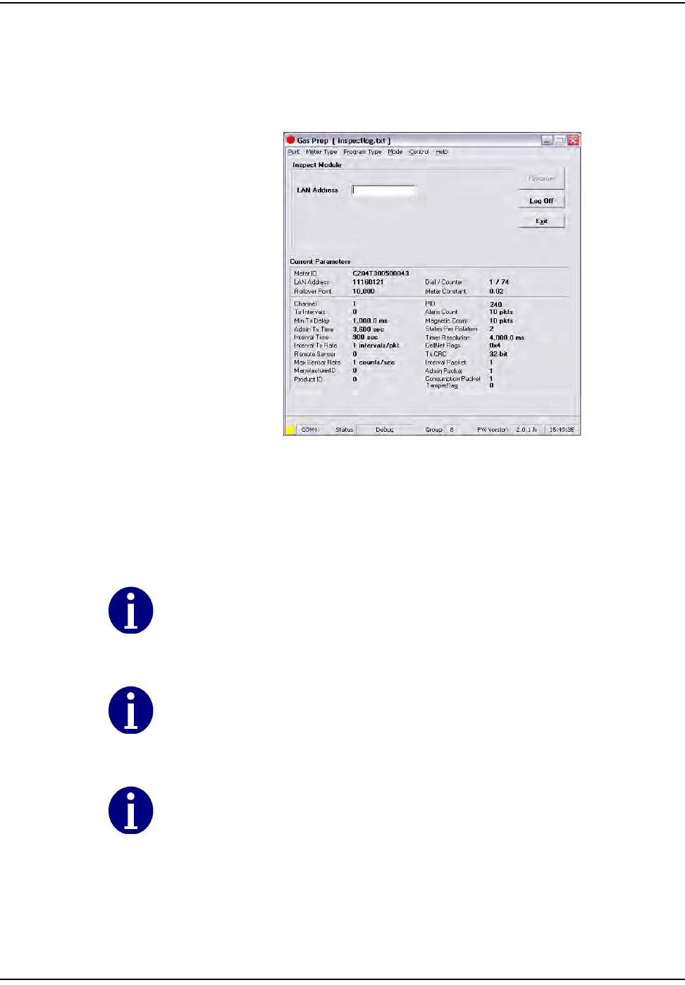
2 Connecttheshootercabletothemoduleprogrammingport.Thefollowing
screendisplays.
Figure 9.9 “Inspect Mode” Screen With Module Plugged In
GPrepautomaticallyreadsanddisplaysthecurrentparametersprogrammedinto
themodule.
If the Meter Type selected does not match the module under test, GPrep displays a dialog
box indicating “wrong module Type” along with a blinking “Module reject” message.
GPrep does not allow the operator to continue with this function.
If the current parameters do not match the predetermined values, a warning message
displays. (This is normal for new modules because a module coming from the
manufacturer is programmed with test parameters).
Module PCB ID (board ID) is populated during manufacturing. Upon verification of module
inspection, this value is saved in combination with the module Power LAN Address in the
Inspect file along with date, operator’s name and location of inspection.
d~ë=jÉíÉê=mêÉé~ê~íáçå=mêçÖê~ã=EdmêÉéF
VJNS `ÉääåÉí=d~ë=jçÇìäÉ=~åÇ=jÉíÉê=fåëí~ää~íáçå=dìáÇÉ
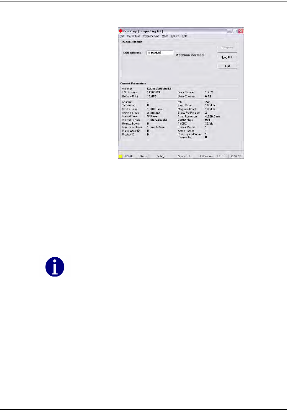
3Scan(enter)theModuleIDinLANAddressfield.
Figure 9.10 “Inspect Mode” With Power LAN Scanned In
GPrepcomparestheModuleIDenteredinthisfieldwiththeLANAddress
programmedintothemodule.Ifthepopulatedfieldmatchestheprogrammed
value,amessagedisplays“addressverified”.Iftheenteredvaluedoesnotmatch
theprogrammedvalueadialogboxdisplays,statingthe“LANAddressdoesnot
matchtheprogrammedvalue”andinstructstheoperatortoreenterthepower
LANlabelvalue,duetoamisinterpretationormis‐enteredvalue.GPrepinstructs
theoperatortoroutethemoduletoMRBforfurtherdispositioniftheentered
valuesdonotmatchagain.
IfthepowerLANvaluedoesnotmatchtheprogrammedvalue,arecordisalso
generatedinthe“inspectfile”showingtheinspectionhasfailed.Modulesthatfail
inspectionmustbesegregatedandroutedtoMRB.
If the result of the inspection is verified, a record in the “inspect file” is created showing
that the module Inspection is successful. It also captures the PCB ID of the module in the
same record.
d~ë=jÉíÉê=mêÉé~ê~íáçå=mêçÖê~ã=EdmêÉéF
`ÉääåÉí=d~ë=jçÇìäÉ=~åÇ=jÉíÉê=fåëí~ää~íáçå=dìáÇÉ VJNT
MODULE PROGRAMMING
Therearetwomodesforprogrammingthemodules.ProgramNewisusedwhen
amoduleisinstalledonanewmeterwithanindexthatreadszero,andRe‐
programoldisusedforprogrammingamodulethatisbeinginstalledonameter
thathasanindexwithavalueotherthanzero.Thisvalueisprogrammedintothe
moduletologinthestartingreadforametertobeinstalled.
(Anexampleofthisisaperiodicmetercheckinwhichameteristakenfroma
residence,inspectedandthenre‐deployedagainintoanotherresidence).
Program New
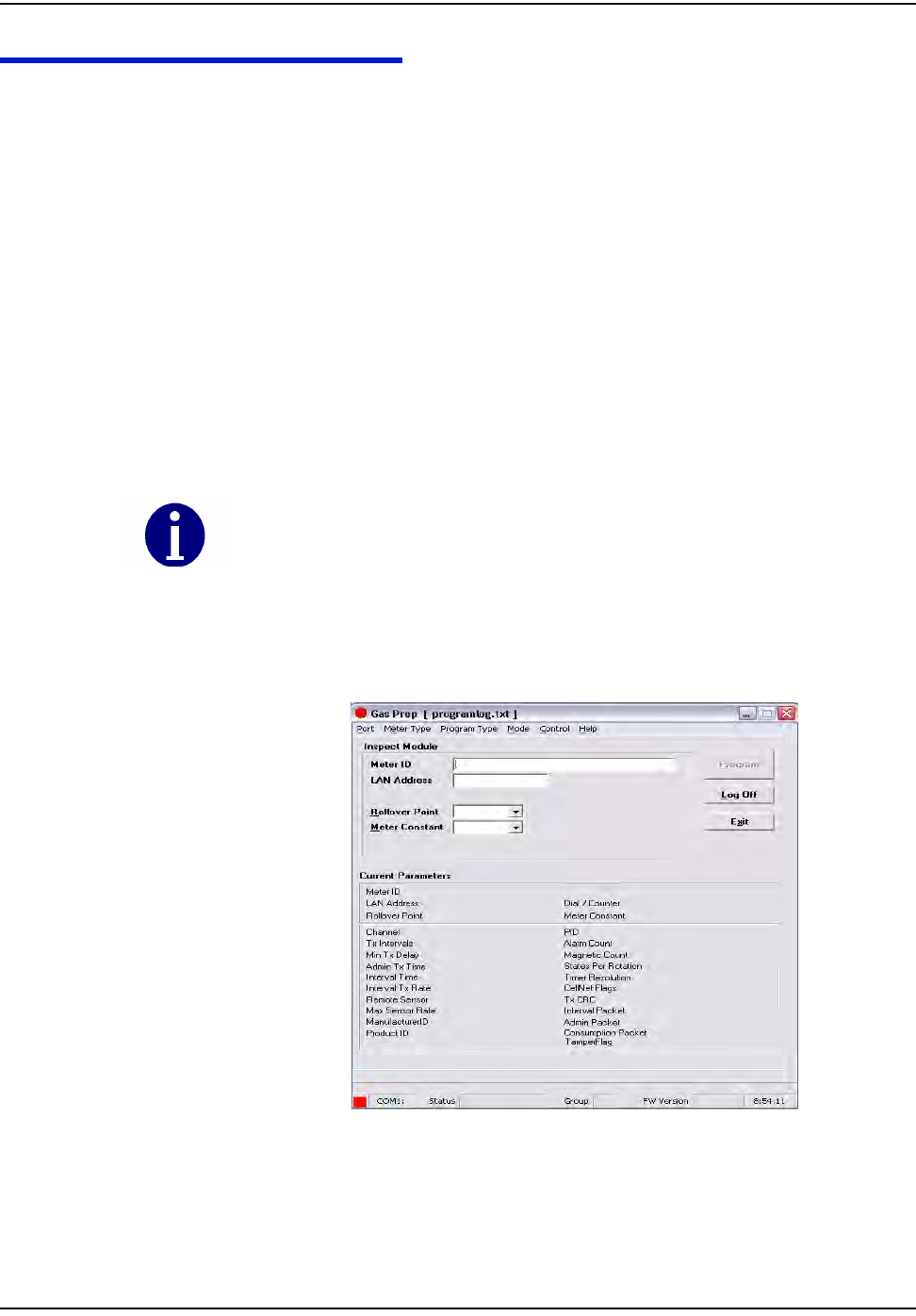
1SelectProgramnewfromthemodedropdownwindowinthemainmenu.
Thefollowingscreendisplays.
Therearetwodistinctsectionsinthisscreenaswell.Thetopsectioncontainsthe
followingfieldswhichcanbemodifiedbytheuser:
•MeterIDfield
•LANAddress
•Roll‐overpoint
•Meterconstant.
Figure 9.11 “Program New” Screen
If you are programming a Water CPR module, Device ID replaces Meter ID. A CPR module is
programmed with 10-digit left-justified(zero) Module ID as MeterID. Water CPR
programming also captures optional Encoder ID information.
d~ë=jÉíÉê=mêÉé~ê~íáçå=mêçÖê~ã=EdmêÉéF
VJNU `ÉääåÉí=d~ë=jçÇìäÉ=~åÇ=jÉíÉê=fåëí~ää~íáçå=dìáÇÉ
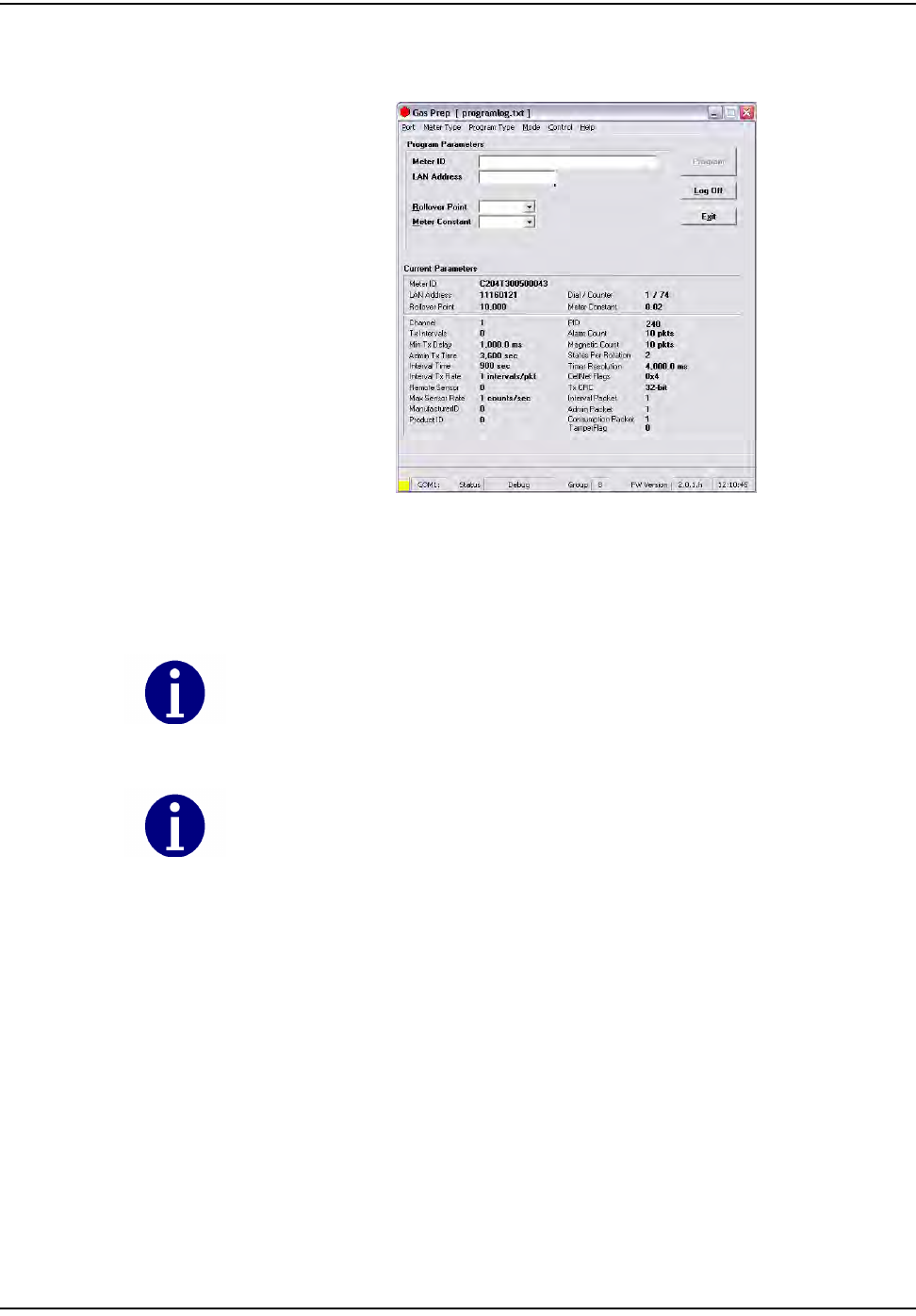
2 Connectthe1‐WayProgrammingCableorshootercabletothemodule
programmingport.Thefollowingscreendisplays.
Figure 9.12 “Program New” Screen with Module Plugged In
GPrepautomaticallyreadsanddisplaysthecurrentparametersprogrammedinto
themodule.
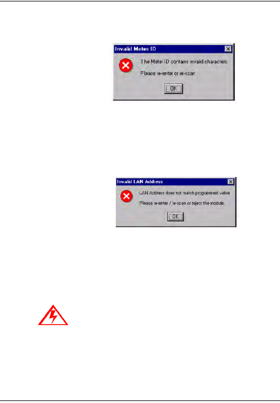
3ScanorenterthemeterIDinappropriatefield.
SincethemeterIDfieldisutilityspecific,thereareprovisionswithinGPrepto
specifythemeterIDformat.Therefore,ifthemeterIDformatenteredinthisfield
doesnotmatchthespecifiedutilityformat,adialogwindowdisplaysindicating
“meterIDfieldcontainsinvalidcharacters”andtheoperatorisinstructedto
If the Meter Type selected on the menu bar does not match the module type under test,
GPrep displays a dialog box indicating “wrong module Type” and a blinking “Module
reject” message. GPrep does not allow the operator to resume the programming function.
If the current parameters do not match the predetermined value, a warning message,
”reject parameters” displays. Upon successful completion of module programming, GPrep
populates the “current parameter” fields with correct operational values.
d~ë=jÉíÉê=mêÉé~ê~íáçå=mêçÖê~ã=EdmêÉéF
`ÉääåÉí=d~ë=jçÇìäÉ=~åÇ=jÉíÉê=fåëí~ää~íáçå=dìáÇÉ VJNV
eitherrescanorre‐enterthemeterIDvalueinthisfield.Moduleprogramming
cannotberesumeduntilthemeterIDfieldpopulatedmatchestheutilityspecific
format.
Figure 9.13 Error Message Displayed when The Wrong Meter ID Format Is Entered
4Scan(enter)thepowerLANlabelintheLANAddressfield.
“GPrep”comparesthevalueenteredinthisfieldwiththeLANAddress
programmedinthemodule.Similartotheinspectionsection,anydiscrepancies
inthevaluesarerejected.
Figure 9.14 Error Message Displayed if The Scanned Power LAN Does Not Match Programmed
SelecttheRolloverPointandMeterConstant(meterspecificvalues)priorto
programmingthemodulefromthedropdownwindows.GPrepdisplaysa
messagewindowverifyingthattheoperatorintendstochangetheRolloverpoint
andmeterconstant.GPrepkeepsthelastvalueenteredintherolloverpointand
meterconstantfieldsasthedefaultvalue.
If you do not know what to enter for the Rollover Point or Meter Constant STOP!
Contact someone that does know or contact Cellnet Customer Support. The wrong
data entered in these fields significantly affects the billing read provided to the
utility.
d~ë=jÉíÉê=mêÉé~ê~íáçå=mêçÖê~ã=EdmêÉéF
VJOM `ÉääåÉí=d~ë=jçÇìäÉ=~åÇ=jÉíÉê=fåëí~ää~íáçå=dìáÇÉ
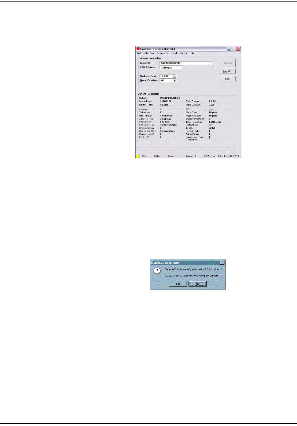
Uponsuccessfulprogramming,amessage“programverified”displays.GPrep
alsodisplaysagreensquareindicatoratthelowerleftcornerofthescreen
showingprogramminghasbeensuccessful.
Figure 9.15 Display when parameters are verified
Arecordofthemeterandmoduleassociationisautomaticallycapturedinthe
“programfile”includingthedateandtheoperator’sname.
The“Programlog”onlycompilestherecordswhensuccessfulprogrammingis
verified.IfaMeterIDrecordalreadyexistsinprogramlog,thefollowingmessage
displays..
Figure 9.16 Error Message Indicating that a Meter ID Already Exists in the Programlog
•IfyouselectʺYesʺ,anewrecordisinsertedwithatimestamp.Itisavalidnew
recordiftheprogramindicatesʺsuccessfulʺ.IfyouselectʺNoʺ,theoldrecord
remains.
d~ë=jÉíÉê=mêÉé~ê~íáçå=mêçÖê~ã=EdmêÉéF
`ÉääåÉí=d~ë=jçÇìäÉ=~åÇ=jÉíÉê=fåëí~ää~íáçå=dìáÇÉ VJON
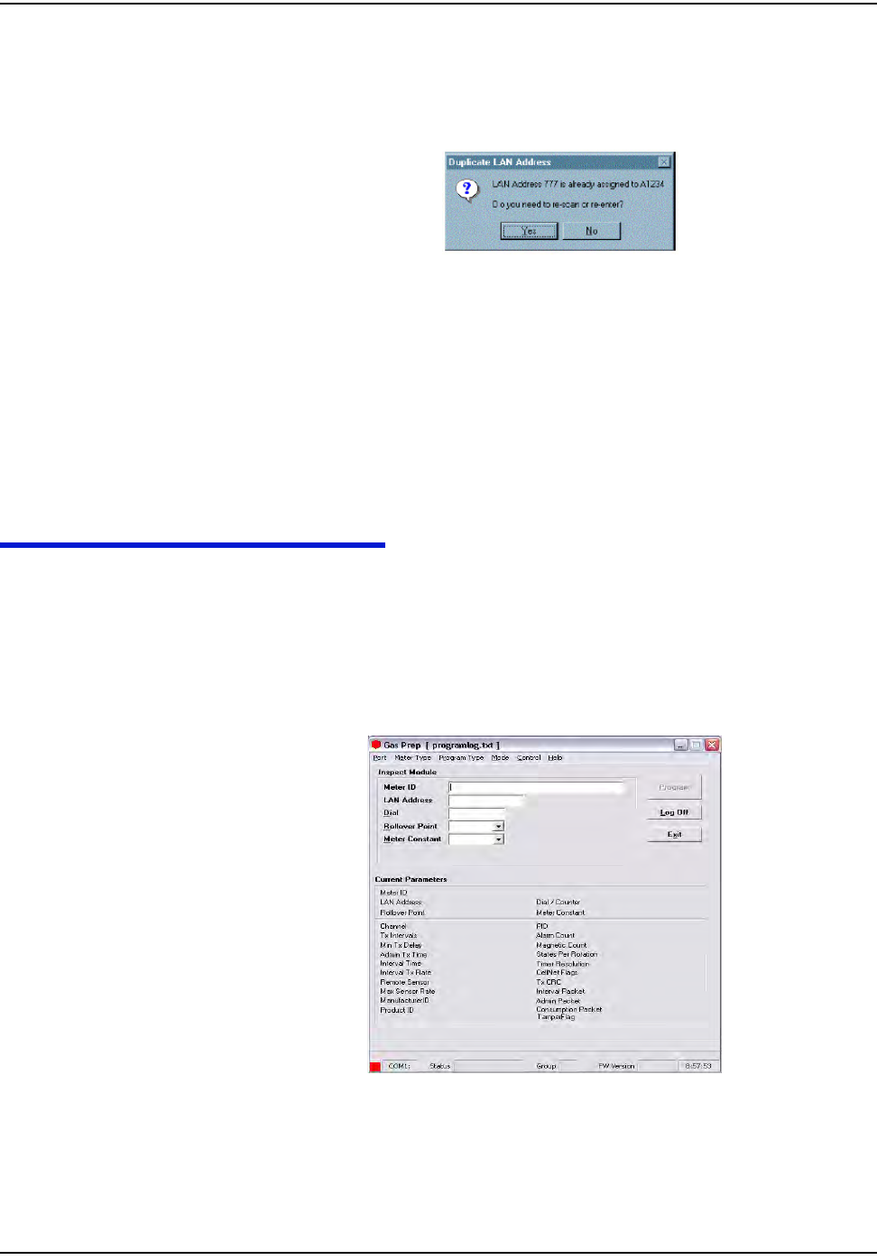
•IfarecordalreadyexistintheprogramlogforascannedmodulePowerLAN
Address,GPrepdisplaysthefollowingmessage:
Figure 9.17 Duplicate Power LAN Address
•Ifyouselect“yes”,indicatingthatyouenteredthewrongmoduleID,thenre‐
enterthemeterIDfieldandPowerLANAddresstocorrectpossiblemis‐
enteredvalues.
•Ifyouselect“No”,indicatingthemoduleIDhasbeenenteredcorrectly,
GPrepdisplaysablinkingmessage“routetoMRB”.
TheresultofthisoperationisnotcapturedintheGPrepprogramlogfile.
RE-PROGRAM OLD
TheinstructionsandproceduresforRe‐ProgramOldarethesameasthosefor
ProgramNew,withtheadditionalfield“Dial”.Populateitwiththeindexreading
(dialreading).ThismodeismainlyutilizedduringtheO&Mphasetoprogram
meterswithnon‐zeroindices.
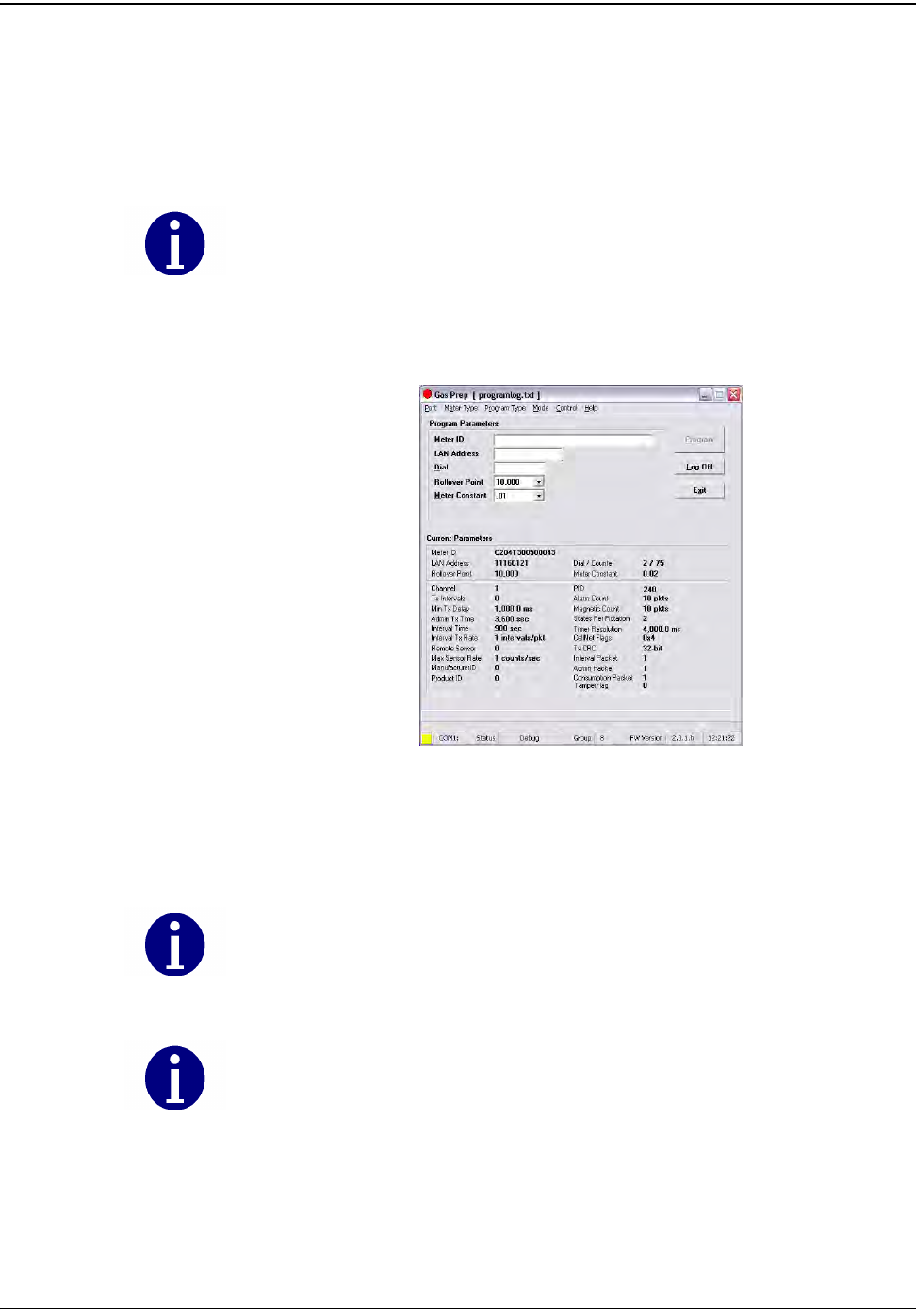
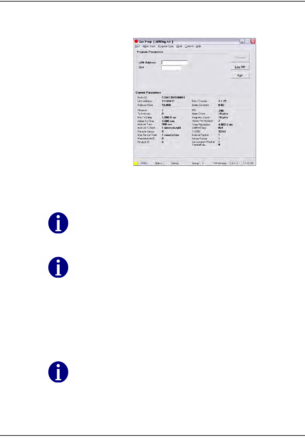
1SelectRe‐ProgramOldfromthemodedropdownwindowinthemain
menu.Thefollowingscreendisplays.
Figure 9.18 “Re-Program Old” Screen
Therearetwodistinctsectionsinthisscreenaswell.Thetopsectioncontainsthe
followingfieldswhichcanbemodifiedbytheuser:
d~ë=jÉíÉê=mêÉé~ê~íáçå=mêçÖê~ã=EdmêÉéF
VJOO `ÉääåÉí=d~ë=jçÇìäÉ=~åÇ=jÉíÉê=fåëí~ää~íáçå=dìáÇÉ
•MeterIDfield
•LANAddress
•Dial
•Roll‐overpoint
•Meterconstant
2 Connectthe1‐WayProgrammingCableorshootercabletothemodule
programmingport.Thefollowingscreendisplays.
Figure 9.19 Re-Program Old With Module Plugged In
GPrepautomaticallyreadsanddisplaysthecurrentparametersprogrammedinto
themodule.
Thisfunctionalityensuresthatthecorrectmetertypeischosenforagivenmeter.
3Scan(enter)themeterIDinappropriatefield.
SincethemeterIDfieldisutilityspecific,thereareprovisionswithinGPrepto
specifythemeterIDformat.Therefore,ifthemeterIDfieldformatenteredin
These are the only fields that can be populated.
If the current parameters do not match the predetermined value, a warning message,
“reject parameters” displays. Upon successful completion of module programming,
“GPrep” populates the “current parameter” fields with correct operational values.
If the meter type selected from the “meter type” drop down menu does not match the
module type, GPrep displays a message “wrong module type” and a blinking message
“reject module”.
d~ë=jÉíÉê=mêÉé~ê~íáçå=mêçÖê~ã=EdmêÉéF
`ÉääåÉí=d~ë=jçÇìäÉ=~åÇ=jÉíÉê=fåëí~ää~íáçå=dìáÇÉ VJOP
thisfielddoesnotmatchthespecifiedutilityformat,adialogwindow
displaysindicating“meterIDfieldcontaininvalidcharacters”andthe
operatorisinstructedtoeitherrescanorre‐enterthemeterIDvalueinthis
field.ModuleprogrammingcannotberesumeduntilthemeterIDfield
populatedmatchestheutilityspecificformat.
4Scan(enter)theModuleIDinLANAddressfield.
GPrepcomparesthevalueenteredinthisfieldwiththeLANAddress
programmedinthemodule.Similartoinspectionsection,anydiscrepanciesin
thevaluesarerejected.
5Entertheindexdialvaluesbyreadingthedialsandenteringthevaluesread
fromrighttoleft.
Figure 9.20 Error Message Displayed when Entered Read is too large for the Rollover Point
Select the Rollover point and meter constant (meter specific values) prior to programming
the module from the drop down windows. “GPrep” displays a message window verifying if
indeed the operator intends to change the Rollover point and meter constant. “GPrep”
keeps the last value entered in rollover point and meter constant fields as default value.
If you do not know what to enter for the Rollover Point or Meter Constant STOP!
Contact someone that does know or contact Cellnet Customer Support. The wrong
data entered in these fields significantly affects the billing read provided to the
utility.
The value entered in the dial field is programmed into the module as the starting meter
read at installation. Consumption is based on the initial read programmed into the module.
It is very important to be accurate on the dial index read. Note also that the dial field
requires the number of digits that correspond to the roll over point.
Example: If the roll over point is set at 10,000, then a four digit dial read would need to be
entered.
The index must have four dials if the roll over point of 10,000 is correct. Otherwise, the roll
over point must be changed accordingly. If the index read number contains more digits
than the corresponding rollover point, GPrep displays the following message prompting the
operator to reenter the index read and a blinking message in the main screen “dial
rejected” is also displayed.
d~ë=jÉíÉê=mêÉé~ê~íáçå=mêçÖê~ã=EdmêÉéF
VJOQ `ÉääåÉí=d~ë=jçÇìäÉ=~åÇ=jÉíÉê=fåëí~ää~íáçå=dìáÇÉ
SelecttheproperMeterConstantfromthedropdownbox.Youcantypically
determinetheMeterConstantfromthemeterindex.
Uponsuccessfulprogrammingamessage“programverified”displays.GPrep
alsodisplaysagreensquareindicatoratthelowerleftcornerofthescreen
showingthattheprogramminghasbeensuccessful(thisisthesameasthe
“verified”screenforProgramNew).Arecordofmeterandmoduleassociationis
automaticallycapturedinthe“programlog”includingtheindexreadenteredby
operatorasopeningread.
MRB MODE
MRB(MaterialRepairBoard)Modecapturestherecordofmeter‐module
disassociationdisassemblyasthemodulesareremovedfromthemeters.
1Selectthemetertypefromthemenubarcorrespondingtothemeter–module
combination.
2SelectMRBfrommodeinthemenubar.Thefollowingscreendisplays.
Figure 9.21 MRB Mode Main Menu
Therearetwodistinctsectionsonthisscreenaswell.Thetopsectioncontainsthe
followingfields:
•LANAddress
•Dial
These are the only fields that can be populated.
d~ë=jÉíÉê=mêÉé~ê~íáçå=mêçÖê~ã=EdmêÉéF
`ÉääåÉí=d~ë=jçÇìäÉ=~åÇ=jÉíÉê=fåëí~ää~íáçå=dìáÇÉ VJOR
3 Connectthe1‐WayProgrammingCableorshootercabletothemodule
programmingport.Thefollowingscreendisplays.
Figure 9.22 MRB Screen with Module Plugged In
4Scan(enter)theModuleIDinLANAddressfield.
GPrepcomparesthevalueenteredinthisfieldwiththeLANAddress
programmedinthemodule.
GPreprejectsanydiscrepanciesinvalues,andpromptsyoutore‐entertheLAN
Addressorrejectthemodule.
5Entertheindexdialvaluesbyreadingthedialsandenteringthevaluesread
fromrighttoleft.
If the Meter Type selected on the menu bar does not match the module type under test,
GPrep displays a dialog box indicating “wrong module Type” and a blinking “Module
reject” message. GPrep does not allow the operator to resume programming function.
If the current parameters do not match the predetermined value, a warning
message,”reject parameters” displays.
The value entered in the dial field are be compared with the module’s programmed read.
GPrep displays the following screen if there is any discrepancy and provides the option to
change the dial read if the operator has entered the wrong value

d~ë=jÉíÉê=mêÉé~ê~íáçå=mêçÖê~ã=EdmêÉéF
VJOS `ÉääåÉí=d~ë=jçÇìäÉ=~åÇ=jÉíÉê=fåëí~ää~íáçå=dìáÇÉ
Figure 9.23 Error Message Displayed when Entered Value Does Not Match Programmed Value
Ifyouselect“Yes”,GPrepdisplaysablinkingmessagestating“Dialdiscrepancy”
andthemainscreendisplaysthatthenewdialvaluehasbeenloggedinMRBlog.
ThisiscapturedintheMRBlogas“dialEntered”.GPrepdoesnotcapturetheold
valuethatwasprogrammedintothemodule.
Ifyouselect“No”,GPreppromptstheoperatortoenterthecorrectvalue.
UponacceptanceofenteredvaluesforLANAddressanddial,GPrepcreatesa
recordintheMRBincludingtheclosingindexreadand“DialVerified”in
additiontotheassociationrecords.
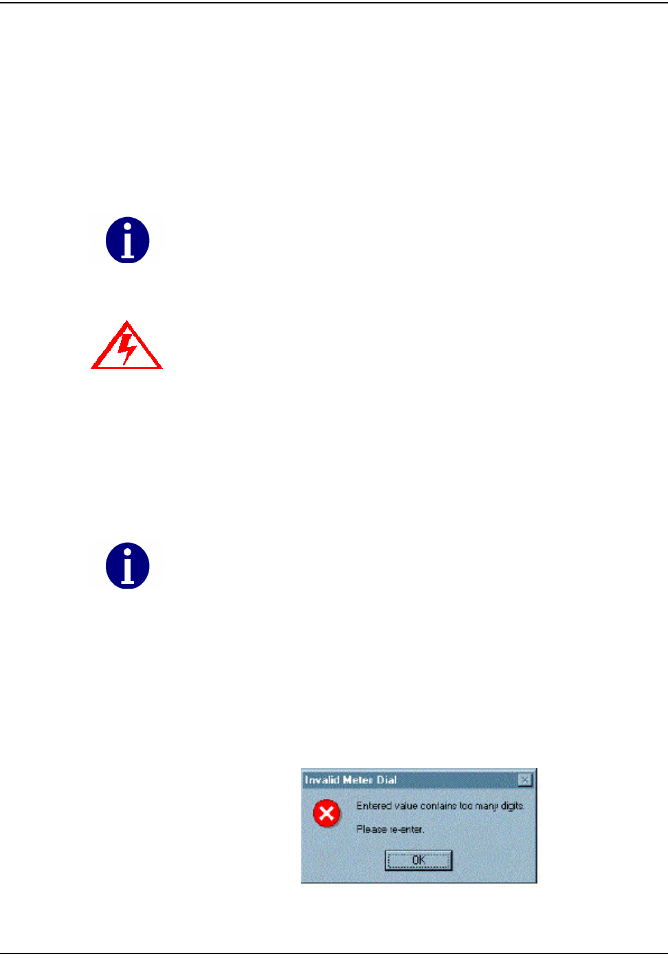
Thedialfieldrequiresthenumberofdigitsthatcorrespondtotherolloverpoint
previouslyprogrammedintothemodule.Example:Iftherolloverpointissetat
1,000,thenafourdigitdial(orless)readwouldneedtobeentered.Theindex
musthavefourdialsiftherolloverpointof10,000iscorrect.Iftheindexread
numbercontainsmoredigitsthancorrespondingrolloverpoint,GPrepdisplaysa
message“enteredvaluecontainstoomanydigits”promptingtheoperatortore‐
entertheindexreadandablinkingmessageinthemainscreen“dialrejected”is
alsodisplayed.

d~ë=jÉíÉê=mêÉé~ê~íáçå=mêçÖê~ã=EdmêÉéF
`ÉääåÉí=d~ë=jçÇìäÉ=~åÇ=jÉíÉê=fåëí~ää~íáçå=dìáÇÉ VJOT
MOST COMMONLY ASKED QUESTIONS
1WhatdoesGPrepstandfor?
GasTOMMPreparation
2WhatisGPrepusedfor?
GPrepisatoolthatisusedintheCrossDockormetershoptoprogramgasor
waterCPRmoduleswithouttheuseofahandheld.Itisalsousedto
disassociategasorwaterCPRmodulesfrommeters.
3W
h
atisprogrammedintothemodule?
IntheʺProgramNewʺandʺRe‐ProgramOldʺmodes,fieldoperating
parametersareprogrammedintothemodule.MeterID,RolloverPoint,Dial
Read,andMeterConstantaretheonlyparametersthatcanbechangedbythe
operator.
4Howdoesameterconstantwork?
Ameterconstantisamultiplierthatconvertsthepulses/turnsofthemodule
intocubicfeet.Thereasonforthemeterconstanttobe.02onameterwitha
2ftdriveisthatforeveryrotationofthedrivedogtherehaspassed2cubicft
ofgas.Thisisequivalentto2%or.02or2/100thsof1pointonthesmallestof
thefourdials,whichmeasureshundredsofcubicfeet.Forevery50rotations
ofthe2‐ftdogdial100cubicfeetofgashaspassed.Forevery50rotations,the
1,000dialhasincreased1point(100cubicfeet)andourmodule(ifithappens
totransmitatthatmoment)sendsoutapacketwithacountof50.OCDB
multipliesthe50bythemeterconstant.02togetareadof1,whichwepasson
totheutilityasareadof1forthatmeter.Therefore,ifthemeterconstantwere
falselysetto.01the50rotationswouldbemultipliedby.01andwouldonly
showthatthemeterused50cubicfeetofgas.
5WhydonʹtyouprogramthemeterIDfromthefrontofthemeterintothe
module?
The“UtilityBillingID”getsprogrammedintothemeter;thisisnotusually
thesameastheMeterID.
6Whatisarolloverpoint,howisitused,whyisitimportanttomakesurethat
itisright?
Thenumberatwhichthedialsofameterturnoverandstartatzeroagain.
Forafourdialmeterthenumbersonthedialscannotgoover9999,therefore,
therolloverpointis10000,for5dialmeterstherolloverpointis100,000,etc.It
isimportanttoprogramthecorrectrolloverpointintothemodulesothatour
systemreadmatchesthedialplate.
7W
h
atscreenshouldIuseinthesamplingprocess?
Thereareseveraldifferenttypesofsamplingdonebythemetershop.The
mostcommonaresamplingofCellnet‐readyOEMmeters,andsampling
modulesfromaCellnetmanufacturer,whicharedoneusingthe“inspect”
mode.
8Whoisresponsiblefortransferringthedatafiles,howoften,whowritesthe
scriptstopickupthedatafromtheserver?
Thelocaldatabaseanalystisusuallyresponsiblefortransferringthedata
fromGPreptoRIMS.He/sheshoulddothisdaily(aslongasthereisdatato
transfer).Someoneinthedatabasegroupwritesthescripttoautomatically
pickupthisdatadaily.

d~ë=jÉíÉê=mêÉé~ê~íáçå=mêçÖê~ã=EdmêÉéF
VJOU `ÉääåÉí=d~ë=jçÇìäÉ=~åÇ=jÉíÉê=fåëí~ää~íáçå=dìáÇÉ
9Howsoondoesthedatagetupdatedineachsystemafteramoduleis
programmed?
ACRONjobrunsnightlythatpicksupthedatathatisputontheCellnet
serverandtransfersittoRIMS.Ataminimumthereisaonedaydelay.
10 Whyshouldn’tItakeGPreptothefield?
DatamanagementbecomesdifficultwhenthePCthatGPrepisbeingusedon
isnotatafixedlocation.ThedatathatiscapturedbyGPrepistimesensitive,
customeraccountinformationandshouldbecopiedandtransferreddaily.
TheequipmentthatisusedtooperateGPrepisnotmadetobeusedoutdoors.
IfGPrepistakentothefield,itisvitalthatthedatabetransferredassoonas
possibleuponreturn.
11 WhatdataiscapturedbyGPrep?
Thereiscurrentlynoscreenthatcapturesboththeclosingandopeningreads
onamodule(asneededforindexchanges).MRBmodeshouldbeusedto
disassociatethemodulefromthemeterandcapturetheclosingread.
Program‐oldshouldthenbeusedtore‐programthemodulewiththenew
indexread.
12 WhataresometroubleshootingstepsifGPrepisnotworking?
–Ifyouareusingtheshooterbox,checktheACpower,modulepluggedin,
shooterboxturnedon,correctDB9toDB9(RS232)cable(Non‐Null
Modem),correctCOMport,ensuringthatyouareusingthecorrectmeter
typeandmode,ex.ResGasv.commercial.
–IfyouareusingUSBonewayprogrammingcable,refertothe1‐Way
ModuleProgrammingCablePC/LaptopGettingStartedGuide.
13 Whatarethebenefitsofusingre‐programoldallofthetimeasopposedto
programnew?
Whilesomeprogramsdothis,therearenorealbenefits.Itisalittleeasierto
preparetheprogramlogtosend,butinvolvesextraworkfortheenduser.
14 Whatdoesitmeanwhenafileissuperseded?
Someonemadeamistakeandhadtore‐enterameterIDorLANAddress.
15 Whoisresponsibleforcleaningthesefiles(removingsupersedes,converting
intoanExcelspreadsheet,etc.)?
Typicallysomeonedesignatedbytheutilityperformsthistaskbeforesending
thesefilestothedatabaseanalyst.
16 WhoshouldIcontactifthereisaproblem?
Firstyoushouldcontactalocaldatabaseanalyst.ThentryCellnetCustomer
Supportatcustomersupport@cellnet.com.
17 Whenusingdifferentscreens,whydoesthephrase“parameterreject”flash
yellowwhenIpluginamodulethathasjustcomefromthemanufacturer?
Whenmodulesarebeingmadetherearetestparametersprogrammedinthat
allowthemanufacturertomakethemoduletransmitmorefrequentlythan
every15minutes,andallowsotherteststoberunonthemforquality
reasons.GPrep(orahandheld)replacesthesetestparameterswithfield
parameters.
`ÉääåÉí=d~ë=jçÇìäÉ=~åÇ=jÉíÉê=fåëí~ää~íáçå=dìáÇÉ ^JN
APPENDIX A ALIGNING THE NEW AMERICAN METER DRIVE DOG
CellnetmodifiedthemodulewigglerinMay2005.Themodulewigglernowhas
aslightlydifferentinterfacetothemeterdrivedog.
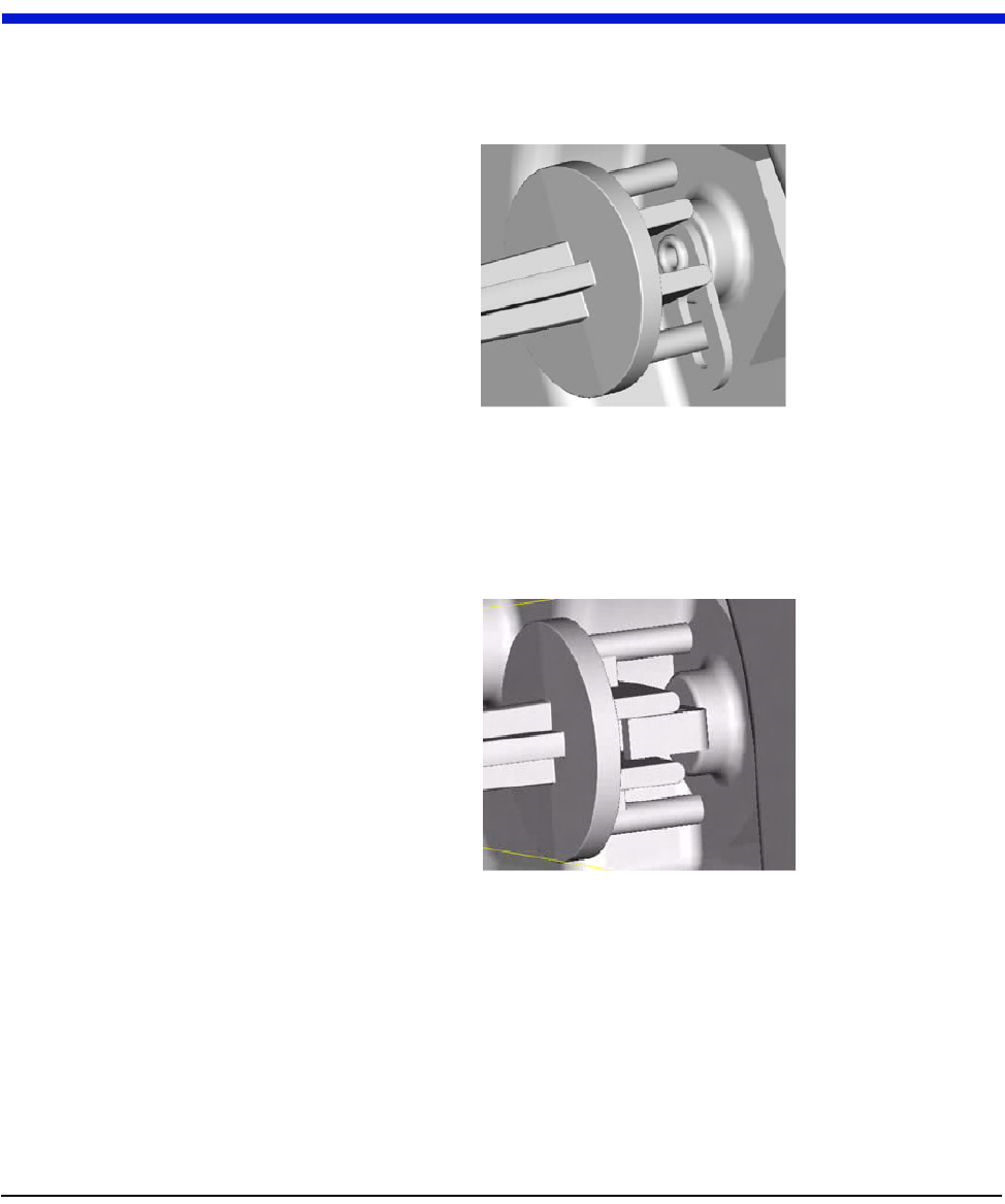
Figure A.1 Meter Drive Dog aligned with 2 ft. module wiggler
Insertoneofthenewprotrudingpinsthroughtheholeofa2‐footdrivewiggler.
Figure A.2 Meter Drive Dog aligned with 1 ft. module wiggler
Insertoneofthenewprotrudingpinsthroughtheholeofa1‐footdrivewiggler.

Notes:
^JO `ÉääåÉí=d~ë=jçÇìäÉ=~åÇ=jÉíÉê=fåëí~ää~íáçå=dìáÇÉ
^äáÖåáåÖ=íÜÉ=kÉï=^ãÉêáÅ~å=jÉíÉê=aêáîÉ=açÖ