Leica Biosystems Nussloch SPECTRACV01 HistoCore SPECTRA CV User Manual Leica SPECTRA CV Instructions for Use V1 2 RevA
Leica Biosystems Nussloch GmbH HistoCore SPECTRA CV Leica SPECTRA CV Instructions for Use V1 2 RevA
Contents
User Manual V1.2 Part 4

94 Version 1.2, Revision A
Daily Instrument Setup
6
6.5 Brief inspection before starting the coverslipping operation
The following points have to be checked again before starting the coverslipping operation:
• Before starting the coverslipping operation, remove the covers of the reagent vessels in the load
drawer and check the level. If necessary, refill the corresponding solvent. The level should reach up
to the label field on the slide for an inserted rack.
• When inserting the loaded rack, ensure that the slide receiving the coverslip has the side with the
specimen pointing towards the user (instrument front).
• Furthermore, check and, if necessary, correct the following before starting the coverslipping
operation:
• Fill level of the mounting medium bottle (→ P. 79 – 6.3.1 Changing the mounting
medium bottle) and of the coverglass cartridge (→ P. 83 – 6.3.3 Checking and
replacing the coverglass cartridge).
• Checking the proper mountant pump function (→ P. 125 – 7.3.1 Quick Prime).
• Filling of the needle cleaning container (→ P. 82 – 6.3.2 Monitoring and refilling of the
needle cleaning container).
• Check for sufficient filling and correct position of the coverglass cartridge (→ P. 83 –
6.3.3 Checking and replacing the coverglass cartridge) and remove any dirt.
• Empty the unload drawer (→ P. 90 – 6.3.7 Unload drawer) and check for dirt.
• Check that the selected parameter set is capable of starting (→ P. 43 – 5.3 Process
status display).
• Check the skids, the suction cups and the coverglass sensor pins for dirt and broken
glass (→ P. 88 – 6.3.5 Inspect Pick&Place module).
• Check the waste tray for broken glass (→ P. 87 – 6.3.4 Emptying the waste tray).
6.5.1 Procedure of the coverslipping operation
LAfter an applicable rack has been inserted into the load drawer and the instrument is ready, the
coverslipping operation begins.
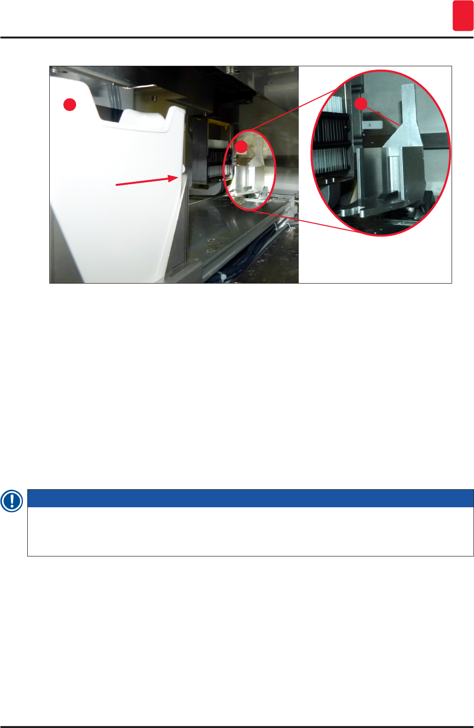
1. The reagent vessel (→ Fig. 72-1) with the rack is moved to the interior of the instrument to the
rotator (→ Fig. 72-2).
2. The gripper lifts the rack out of the reagent vessel and places it in the rotator (→ Fig. 72-2).
3. The rotator brings the slide into the correct position.
95
HistoCore SPECTRA CV
Daily Instrument Setup 6
1
2
2
Fig. 72
4. The gripper picks up the rack once again and places it in the elevator.
5. The elevator moves the rack into the position of the first slide.
6. The shifter transports the slide out of the rack to the coverslipping position with the shifter
tongue.
7. During this movement, the needle applies the mounting medium to the slide.
8. At the same time, the Pick&Place module removes coverglass from the coverglass cartridge
and transports it – via the slide covered with mounting medium – and places the coverglass on
the slide.
9. The lay-down movement provides for the uniform distribution of the mounting medium on the
slide.
10. Afterwards, the shifter pushes the coverslipped slide back to its original position in the rack.
11. The elevator moves to the next slide, which the shifter transports to the coverslipping position.
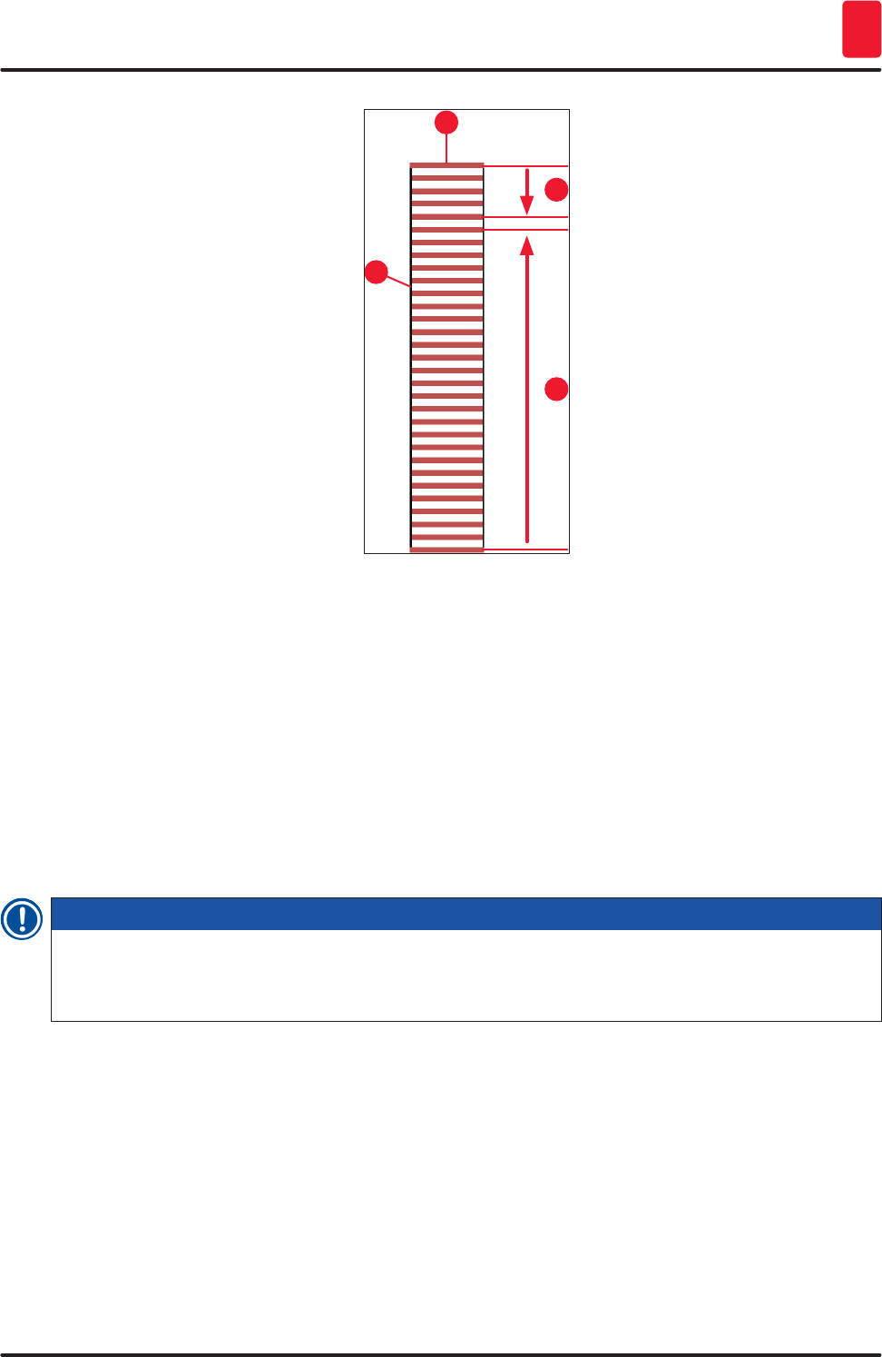
Note
In order to prevent slides from drying out during processing, the first 5 slides are always coverslipped
first. Then the rack moves upwards and continues coverslipping with the last slide in the rack
(→ Fig. 75).
12. This sequence (steps 6 to 11) is repeated until all slides in the rack have been coverslipped.
13. When all slides are coverslipped, the elevator moves the rack downwards into the instrument.
96 Version 1.2, Revision A
Daily Instrument Setup
6
14. The gripper removes the rack from the elevator and transports it into the oven to dry.
15. When the drying time period is complete, the rack is transported out of the oven and into the
unload drawer by the gripper, and is put down in one of the three rear positions.
16. The user will be notified via an information message and can carefully remove the rack out of
the unload drawer.
Note
If the oven step has been disabled or if the oven is completely shut down, the rack is transported –
by the gripper – directly from the elevator into the unload drawer. Proceed carefully while removing
out of the unload drawer, since the mounting medium is not yet completely dry and in the event of
improper removal, coverglass may shift out of place.
6.6 Starting the coverslipping operation
Note
Once initialization is complete and the preparations have been made (→ P. 94 – 6.5 Brief inspection
before starting the coverslipping operation) the coverslipping operation can be started by inserting a
filled rack. It is important to make sure that the rack handle color matches the color of the parameter
sets that is suitable for starting and being carried out.
Warning
• The rack can be inserted only using the load drawer. Accidentally inserting a rack into the unload
drawer can lead to a collision and thus to an instrument fault and a possible loss of specimens!
• Direct insertion in the instrument is not possible!
• Exercise caution when opening or closing the drawers! Crushing hazard! The drawers are
motorized and open or close automatically at the press of a button. Do not block the extension
range of the drawers.
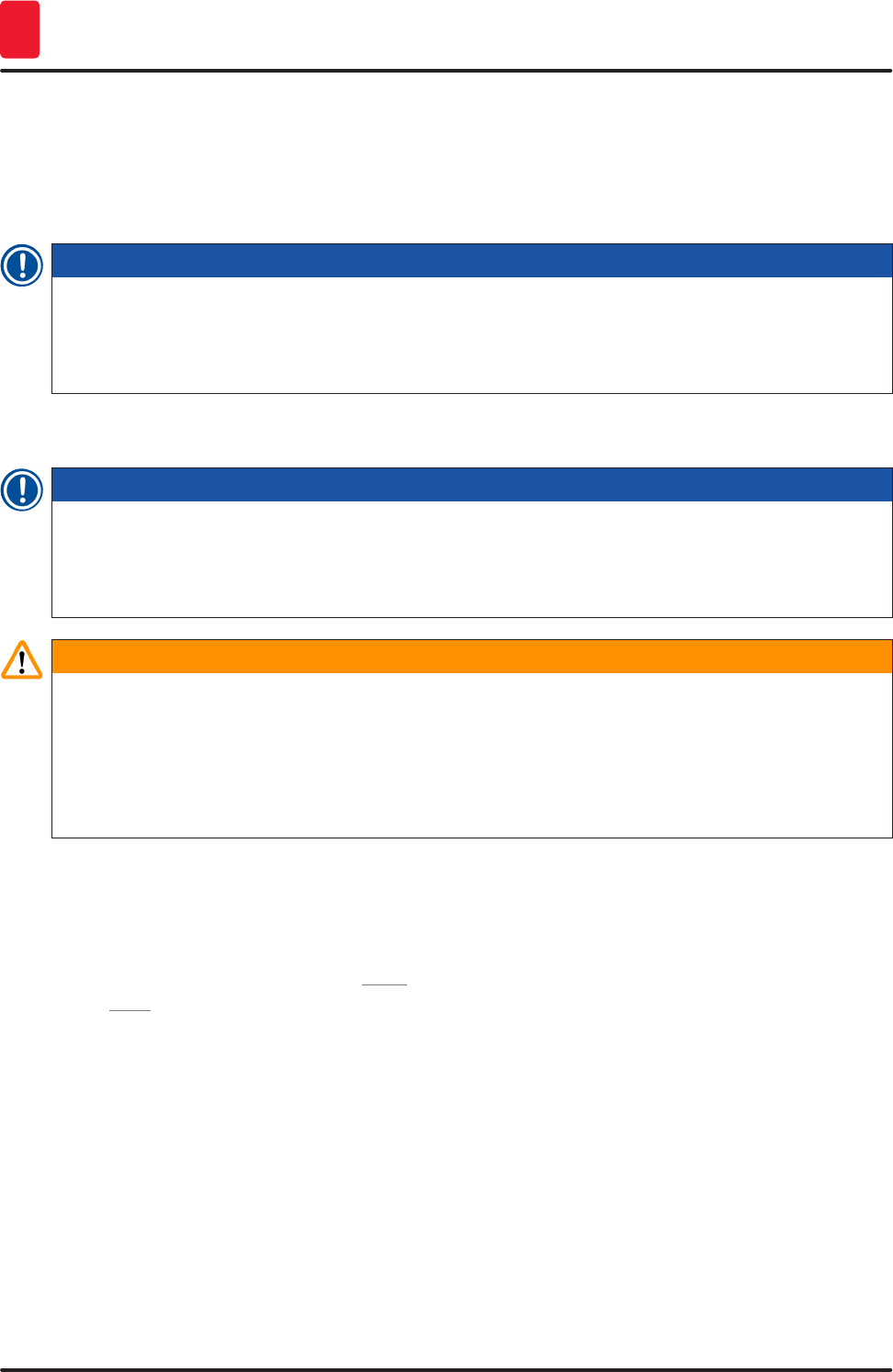
1. Fold the handle of the rack into the upright position (→ Fig. 69-2).
2. If the load drawer (→ Fig. 73-1) button is green, press it and open the drawer.
3. Insert the rack in an available position of the load drawer (→ Fig. 73-2).
4. Insert the rack so that both the Leica logo (→ Fig. 71-1) on the front side of the rack and the
Front (→ Fig. 73-3) on the top of the colored handle are pointing toward the user. The arrow
(→ Fig. 73-4) on top of the colored handle must point into the instrument.
97
HistoCore SPECTRA CV
Daily Instrument Setup 6
1
2
3
4
Fig. 73
5. Press the load drawer button again to close it again.
6. After closing the load drawer, the instrument detects the RFID chip in the colored handle.
7. The detected handle color is shown in the process status display (→ Fig. 74).
Processing starts automatically.
98 Version 1.2, Revision A
Daily Instrument Setup
6
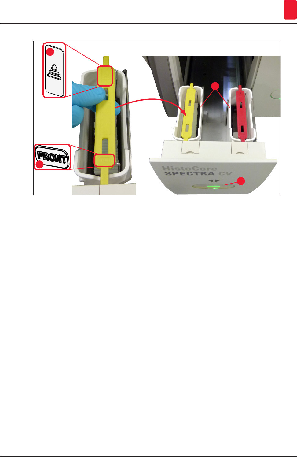
Fig. 74
Note
• The slides are not processed sequentially, i.e. they are not coverslipped in sequence.
• The schematic display (→ Fig. 75) of a rack (→ Fig. 75-1) with used slides (→ Fig. 75-2) shows
the sequence during processing.
• The first five slides are coverslipped at the beginning (→ Fig. 75-3). Then the rack moves upwards
and continues the coverslipping with the lowest slide (→ Fig. 75-4). The sixth slide (counted from
above) is coverslipped last. This procedure prevents the lowest slide from drying out.
• Finished coverslipped slides are moved back to their original position within the rack.
• The instrument detects and indicates when a rack has been inserted in the wrong orientation and
has to be corrected by the user.
• The system detects if a rack has been inserted into the load drawer with a rack handle color for
which no parameter set is active, and the user is informed by a corresponding message. The rack
must be removed from the instrument. Corresponding to the bootable parameter sets (→ P. 43 –
5.3 Process status display), attach the correct colored handle to the rack and re-insert it into the
load drawer.
• Racks that are inserted into the left-side reagent vessel in the load drawer are coverslipped in the
L1 coverslip line. Racks from the right-side vessel are coverslipped in the L2 coverslip line.
99
HistoCore SPECTRA CV
Daily Instrument Setup 6
1
2
3
4
Fig. 75
6.6.1 Monitoring the coverslipping operation
The user can retrieve and monitor details regarding the ongoing coverslipping operations using the
process status display (→ P. 43 – 5.3 Process status display):
• Process status display with calculated remaining coverslipping time, real time at the end of
processing, coverslip line used, parameter set number (→ P. 43 – 5.3 Process status display).
• The status bar (→ P. 42 – 5.2 Elements of the status display) with the date, time, "process" icon,
user status and icons indicating messages and warnings that occurred.
• The position of the rack is detected in the input and unload drawer using RFID.
Note
The last 20 active messages and warnings can be called up by touching the corresponding symbols
in the status bar (→ Fig. 21-4) (→ Fig. 21-5). This allows the user to learn about past and current
situations and to initiate any required actions.
100 Version 1.2, Revision A
Daily Instrument Setup
6
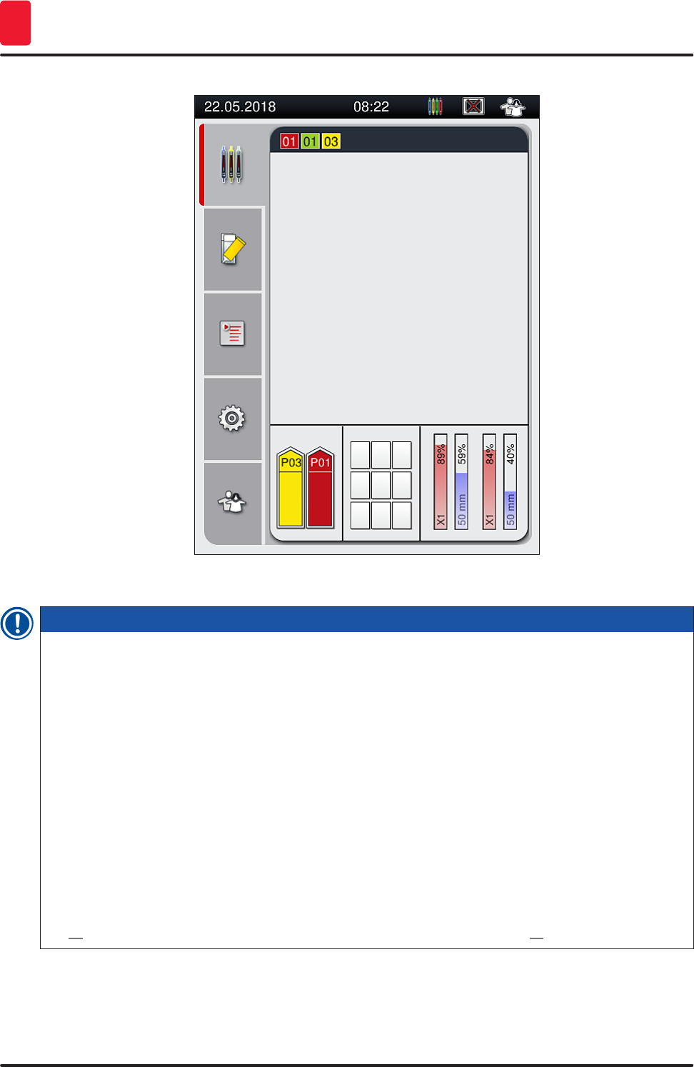
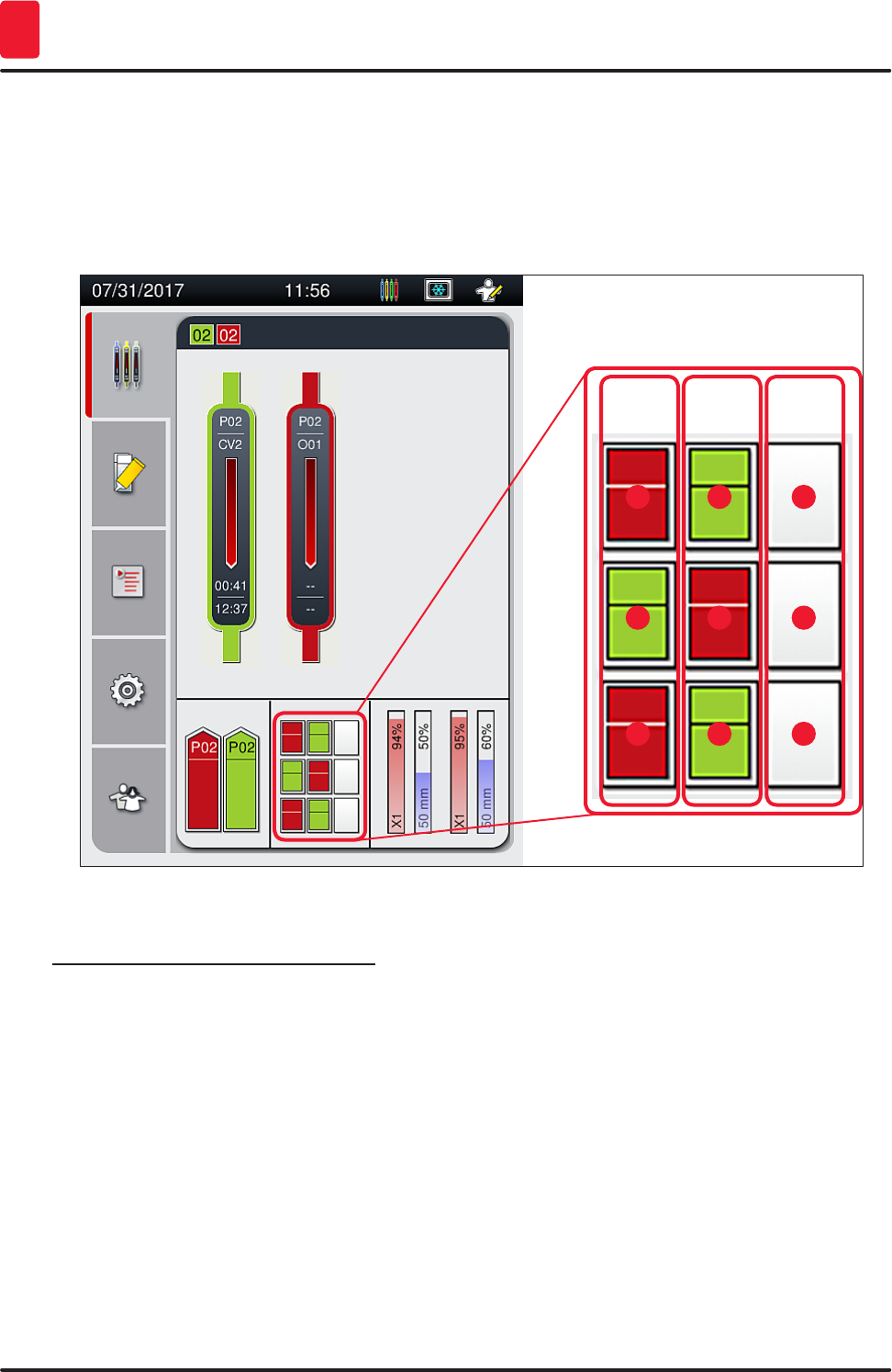
6.6.2 Coverslipping operation finished
• If a rack ran the coverslipping operation, it will be transported in the unload drawer.
• The unload drawer can hold up to 9 racks. The racks are placed in the unload drawer in the sequence
shown from A1 to C9 (→ Fig. 76).
A B C
1
6
2
7
3
8
4
5
9
Fig. 76
Removing racks from the unload drawer
1. Press the button (→ Fig. 51-2) at the unload drawer to open and remove the rack.
2. Press the button again after removal to close the unload drawer.
The status display for the unload drawer is updated after closing the drawer.
101
HistoCore SPECTRA CV
Daily Instrument Setup 6
Note
• After the oven step has ended, the mounting medium is not completely dry. Treat the slides
carefully during the removal from the rack to avoid a sliding of the coverglass.
• Ensure that all racks are always removed from the unload drawer.
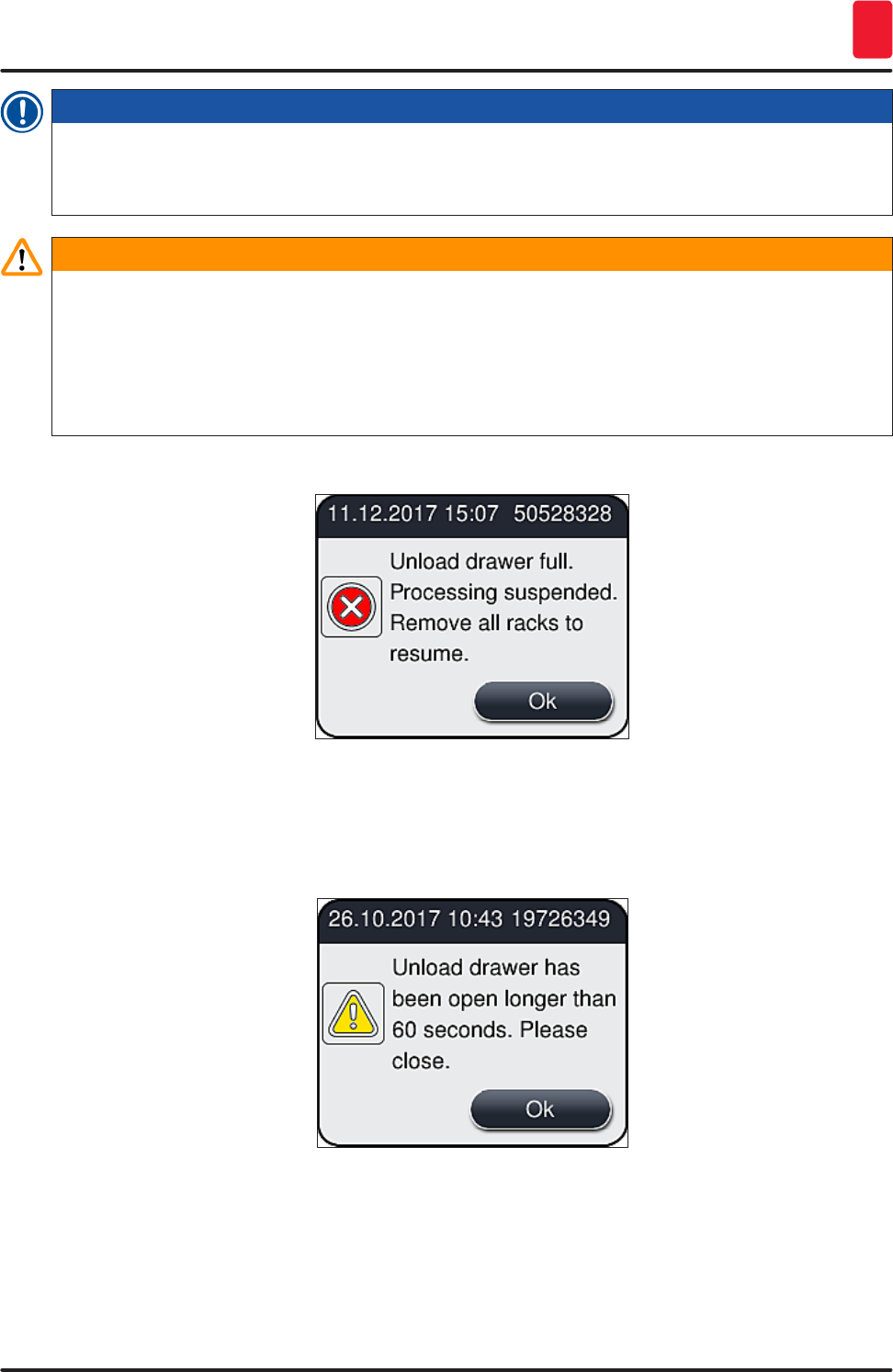
Warning
• The unload drawer must be opened and all racks present must be removed – at the latest – when
the message is received indicating that the unload drawer is completely occupied (→ Fig. 77).
Failure to observe the message may lead to instrument faults and specimen impairment.
• Finished coverslipped racks remain in the oven until all racks are removed from the unload
drawer. The longer dwell time in the oven can lead to specimen impairments.
• If not all racks are removed from the unload drawer, this can lead to sample destruction.
Fig. 77
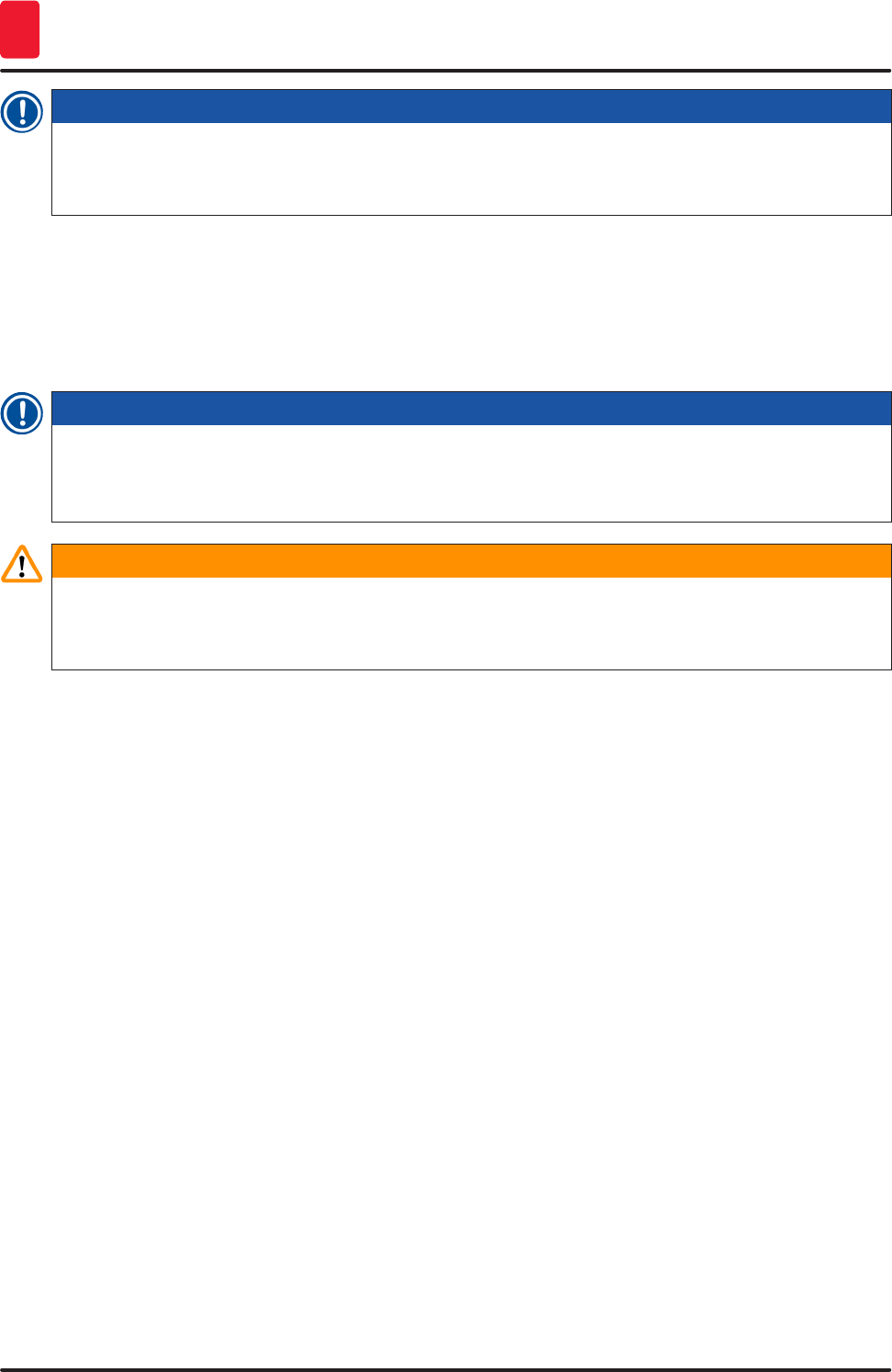
• The user receives an information message (→ Fig. 78) if the unload drawer is open for longer than
60 seconds.
Fig. 78
102 Version 1.2, Revision A
Daily Instrument Setup
6
Note
The warning message prompts the user to close the unload drawer in order to prevent possible
delays in processing. When the unload drawer is open, the instrument cannot place completely
coverslipped racks into the unload drawer.
• The message goes away as soon as the unload drawer is closed.
6.6.3 Pausing or canceling the coverslipping operation
Pausing the coverslipping operation
Note
Opening the hood automatically pauses any coverslipping operations in progress, during which
coverslipping for the most recently processed slide is completed.
Closing the hood allows the coverslipping operations to continue.
Warning
Specimens that have not yet received a coverslip are unprotected at this point (risk of drying out)!
Therefore the hood should only be opened in an emergency during the coverslipping operation
(→ P. 135 – 8. Malfunctions and Troubleshooting).
Canceling the coverslipping operation
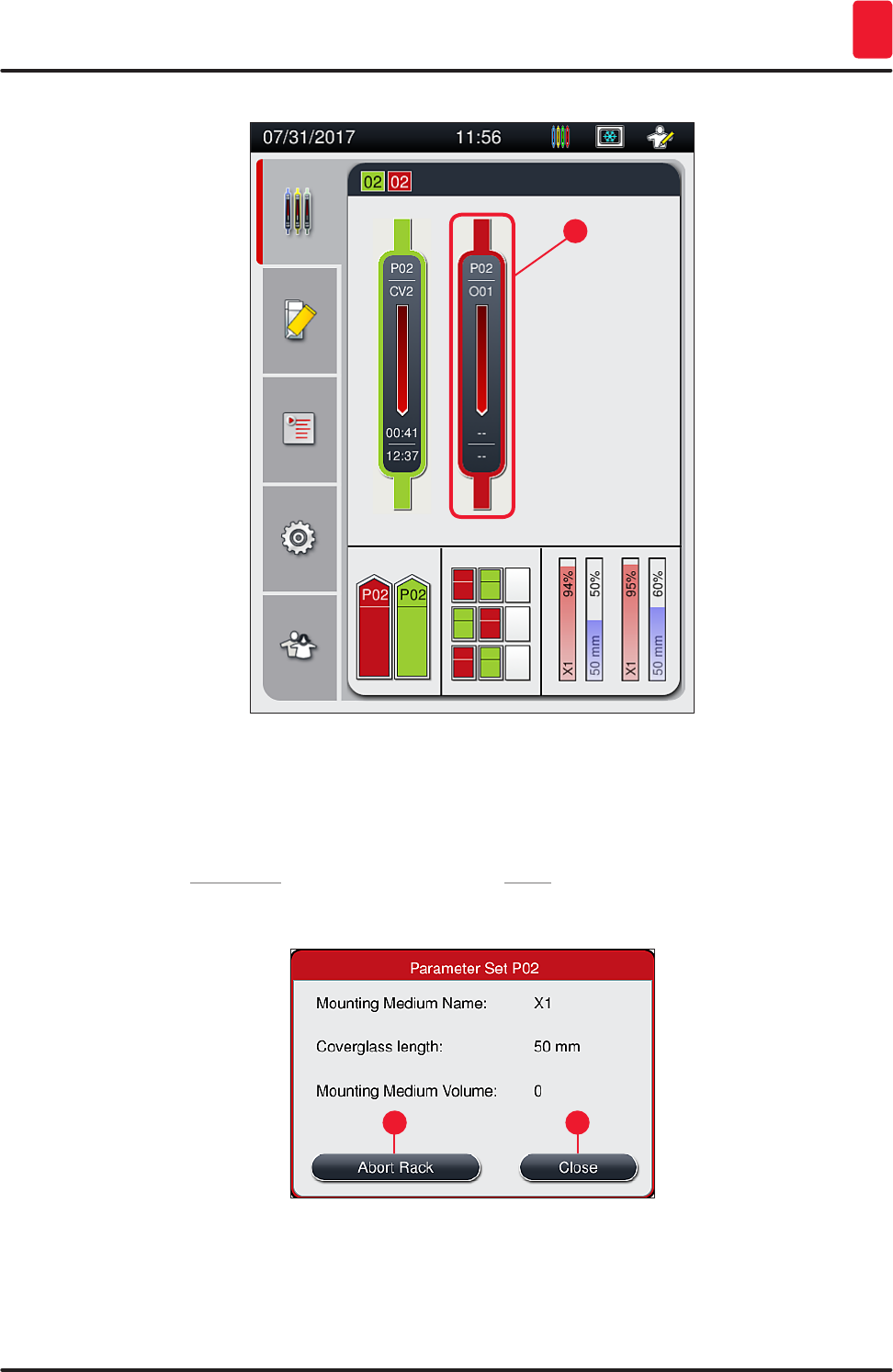
LCoverslipping operations can only be canceled using the process status display (→ Fig. 79).
1. To cancel a coverslipping operation, select the corresponding rack (→ Fig. 79-1) by touching
it.
103
HistoCore SPECTRA CV
Daily Instrument Setup 6
1
Fig. 79
2. An overview appears of the rack for which the process is being canceled (→ Fig. 80).
3. The border of the window shows the color assigned to the parameter set, the mounting
medium used, the coverslip size used and the stored volume.
4. Press the Abort Rack (→ Fig. 80-1) button or the Close (→ Fig. 80-2) button in order to
continue processing for the selected rack.
1 2
Fig. 80
104 Version 1.2, Revision A
Daily Instrument Setup
6
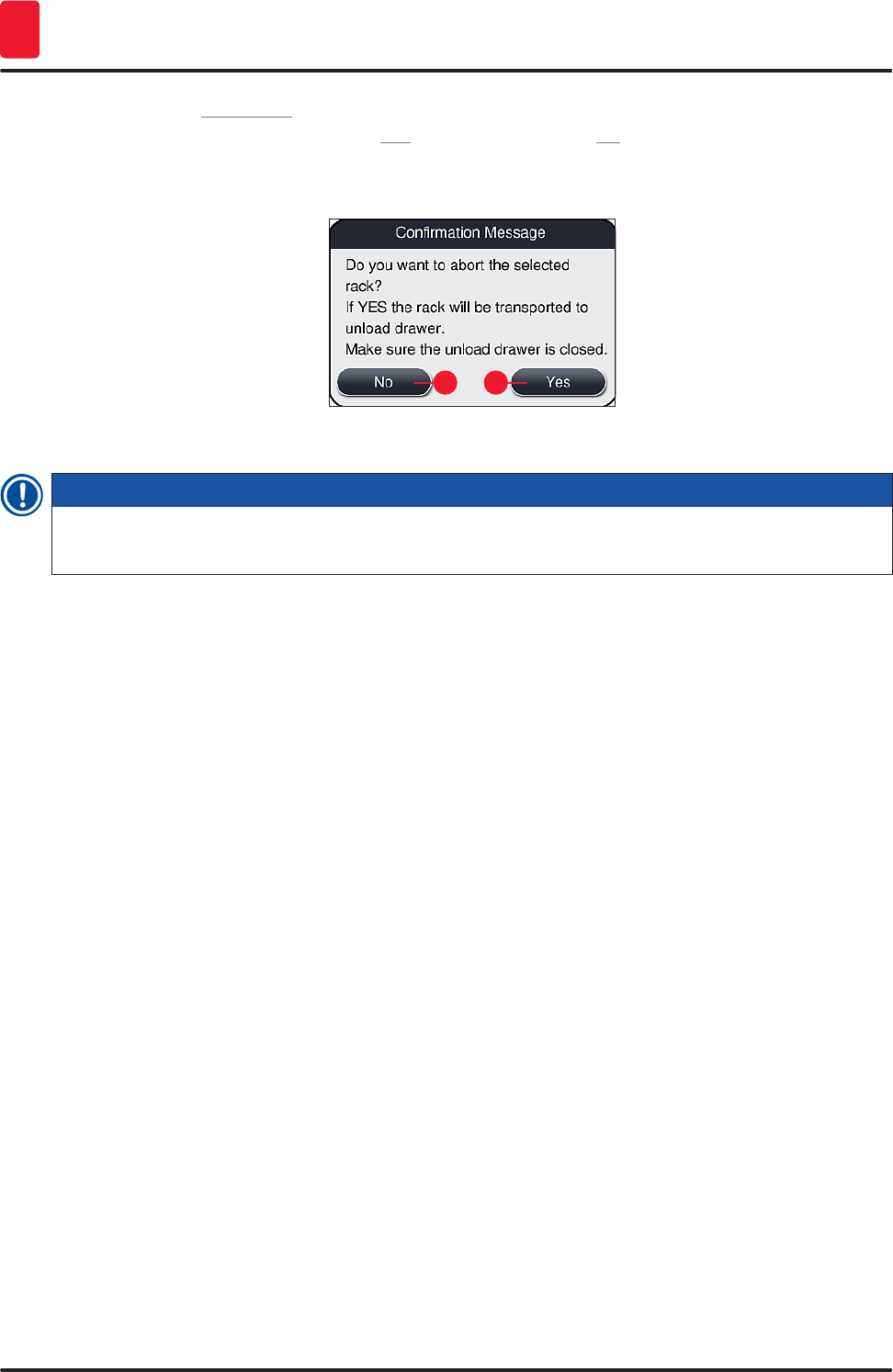
After pressing the Abort Rack (→ Fig. 80-1) button, an information message is displayed (→ Fig. 81).
Confirm the cancellation with the button Yes (→ Fig. 81-1) or press No (→ Fig. 81-2) to return to the
process status display (→ Fig. 79).
12
Fig. 81
Note
After confirming the cancellation, the rack is transported into the unload drawer and can be removed
there.
105
HistoCore SPECTRA CV
Daily Instrument Setup 6
6.7 Workstation operation
6.7.1 Notes on workstation mode
Warning
The user must adhere to the following in workstation operation!
• The last stations of the HistoCore SPECTRA ST must be filled with the same reagent (xylene)
as the reagent vessels in the load drawer of the HistoCore SPECTRA CV in order to prevent
compatibility problems with the mounting medium being used and to prevent drying out the
specimens (→ P. 135 – 8.1 Troubleshooting).
• As a last step, the transfer station is to be indicated in the staining program of the
HistoCore SPECTRA ST so that finished stained racks can be transferred to the
HistoCore SPECTRA CV. The description on the correct generation of staining programs can be
found in the Instructions for Use of the HistoCore SPECTRA ST.
• Using reagents that are incompatible with each other can lead to substantial impairments in
specimen and coverslipping quality.
• If the HistoCore SPECTRA CV cannot accept a rack from the HistoCore SPECTRA ST (e.g. due to an
instrument fault in the HistoCore SPECTRA CV or if the load drawer of the HistoCore SPECTRA CV
is assigned), these will be transported to the HistoCore SPECTRA ST unload drawer.
• The reagent vessels in the unload drawer of the HistoCore SPECTRA ST therefore always have to
be filled with a compatible solvent for the HistoCore SPECTRA CV in order to prevent the tissue
sample from drying out.
• If a longer power failure occurs, proceed as described in (→ P. 139 – 8.2 Power failure scenario
and instrument failure).
• Note that in workstation mode, the HistoCore SPECTRA CV cannot process any racks for 5 slides.
• The instrument detects the manual insertion of racks for 5 slides in the load drawer of
HistoCore SPECTRA CV. An information message prompts the user to remove this rack again from
the load drawer.
Warning
• If racks for 5 slides are used for staining in the HistoCore SPECTRA ST, select the unloader as the
last step in the program. Remove the finished stained slides and place them into a suitable rack
for the HistoCore SPECTRA CV.

106 Version 1.2, Revision A
Daily Instrument Setup
6
Note
• The HistoCore SPECTRA CV can be operated as a workstation together with
HistoCore SPECTRA ST. This allows an uninterrupted workflow from inserting into the stainer up
to removing the completely stained and coverslipped slides from the coverslipper.
• In workstation mode, the racks in the HistoCore SPECTRA ST can either be passed directly to
the unload drawer or directly to the HistoCore SPECTRA CV by means of the transfer station and
placed into a reagent vessel for the load drawer of the HistoCore SPECTRA CV. In the Instructions
for Use for the HistoCore SPECTRA ST, the notes on program creation must be observed.
• The time of transfer of the finished and colored rack to the HistoCore SPECTRA CV is then
separately displayed in the process status display of the HistoCore SPECTRA ST (→ Fig. 82-5).
• After completion of the coverslipping operation, the racks are placed in the unload drawer of the
HistoCore SPECTRA CV.
• If the racks from HistoCore SPECTRA ST are being transferred to the HistoCore SPECTRA CV, the
load drawer of the HistoCore SPECTRA CV is blocked during this time period and racks cannot be
inserted into the HistoCore SPECTRA CV manually.
• The brief inspection before the daily startup (→ P. 94 – 6.5 Brief inspection before starting the
coverslipping operation) must be carried out.
• If the network connection between HistoCore SPECTRA ST and HistoCore SPECTRA CV is
interrupted or HistoCore SPECTRA ST is shut down, the HistoCore SPECTRA CV can only be used
as a standalone instrument. Workstation mode is no longer possible in that case. Only manual
loading using the load drawer is still possible then.
• Both instruments have to be taken out of service separately using their own Operating switch
after operation.
• In order to ensure operation free of interruptions, always leave both instruments switched on and
follow the notes on daily startup (e.g. refilling consumables, removing the cover from the reagent
vessels in the load drawer of the HistoCore SPECTRA CV).
• Resolve any faults immediately if the HistoCore SPECTRA CV has been stopped. Otherwise, altered
staining results can occur in the HistoCore SPECTRA ST because racks where staining has been
completed can no longer be transferred to the HistoCore SPECTRA CV, creating potential for a
backlog.
• Stay within earshot of the instruments so that you can respond to the audible signals immediately.
• In workstation mode it is also possible to place a rack for coverslipping directly in the load drawer
of the HistoCore SPECTRA CV. In doing so, however, the user must ensure that this rack, placed
by hand, is detected by the instrument (→ P. 43 – 5.3 Process status display).
107
HistoCore SPECTRA CV
Daily Instrument Setup 6
6
7
2
3
4
5
1
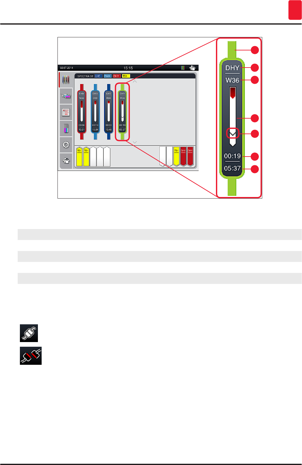
Fig. 82
1Program color
2Abbreviation of the program name
3Current position of the rack in the instrument
4Progress display of the entire staining process
5Time of transfer to the connected HistoCore SPECTRA CV
6Estimated remaining time (hh:mm)
7Time at end of process
On the HistoCore SPECTRA ST status display, a symbol indicates whether there is a connection to a
HistoCore SPECTRA CV or if the connection has been interrupted.
The connection between the HistoCore SPECTRA ST and the HistoCore SPECTRA CV has
been established.
The connection between the HistoCore SPECTRA ST and the HistoCore SPECTRA CV has
been interrupted.
108 Version 1.2, Revision A
Daily Instrument Setup
6
6.7.2 Starting the coverslipping operation in workstation mode
LThe coverslipping operation also starts automatically just like after manually inserting a rack in
the load drawer.
1. Place the rack into the load drawer of the HistoCore SPECTRA ST.
2. Both the staining and coverslipping processes are controlled by the assigned rack handle
color.
3. Racks where the staining and coverslipping processes have been completed are automatically
placed in the unload drawer of the HistoCore SPECTRA CV and have to be removed by the user
there.
LAs soon as a rack is placed in the HistoCore SPECTRA ST that has to be transferred through the
transfer station to the HistoCore SPECTRA CV, the process icon is displayed on the status bar
(→ Fig. 21-7) of the HistoCore SPECTRA CV.
The Process symbol indicates that processing is currently active and that a rack may still
be in the unload drawer or a rack from the HistoCore SPECTRA ST is expected.
Note
In workstation mode it is also possible to place a rack for coverslipping directly in the load drawer of
the HistoCore SPECTRA CV.

109
HistoCore SPECTRA CV
Cleaning and Maintenance 7
7. Cleaning and Maintenance
7.1 Important notes about cleaning this instrument
Warning
• The instrument should always be cleaned after the end of work, but BEFORE the instrument is
shut down. An exception from this is cleaning the interior (→ P. 111 – 7.2.4 Interior cleaning). We
recommend cleaning while the instrument is shut down.
• The regular maintenance intervals must be observed.
• When using cleaners, please comply with the safety instructions of the manufacturer and the
laboratory safety regulations.
• Proceed carefully and wear suitable protective clothing when cleaning the instrument (lab coat,
cut-resistant gloves and safety goggles).
• Never use solvents (such as alcohol, acetone, xylene, toluene etc.) or cleaning agents containing
solvents to clean the exterior of the instrument.
• Prevent liquids from entering the interior of the instrument or electrical contacts while the
instrument is being cleaned or during operation.
• Solvent vapors can develop if solvents are left in the instrument after shutting it down. There is a
risk of fire or poisoning if the instrument is not operated under a fume hood!
• Dispose of used reagents while observing applicable local regulations and the disposal
regulations of your company/lab.
• Shutting down the instrument for longer breaks in work and unplug it at the end of the workday
(→ P. 77 – 6.2 Switching on and shutting down the instrument).
• Immediately use a lint-free cloth to wipe off mounting medium that drips onto/into the instrument
(e.g. during priming or exchanging a mounting medium bottle).
• Make sure that significant amounts of solvent are not spilled in the instrument (danger for the
electronics!). If solvent has been spilled, immediately remove the liquid with an absorbent cloth.
• To prevent damage, never leave plastic accessories immersed in solvent or water for a prolonged
time (e.g. overnight).
• Never clean plastic reagent vessels at temperatures higher than 65 °C since this can deform
reagent vessels!
7.2 Description of cleaning individual instrument components and areas
7.2.1 Exterior surfaces, varnished surfaces, instrument hood
» The surfaces (hood and housing) can be cleaned with a mild, pH-neutral, commercially available
cleaning agent. After cleaning the surfaces, wipe them off with a cloth moistened with water.
Warning
Varnished instrument surfaces and plastic surfaces (e.g. an instrument hood) may not be cleaned
with solvents like acetone, xylene, toluene, xylene substitutes, alcohol, alcohol mixtures and
abrasives! In case of long-term exposure, the surfaces and instrument hood are only conditionally
resistant to solvents.
110 Version 1.2, Revision A
Cleaning and Maintenance
7
7.2.2 TFT touchscreen
» Clean the screen using a lint-free cloth. A suitable screen cleaner can be used in compliance
with the manufacturer information.
7.2.3 Input and unload drawers
Warning
• To avoid an overflowing of a filled reagents, do not open the load drawer suddenly.
• Wear suitable protective clothing (lab coat, safety goggles, cut-resistant gloves).
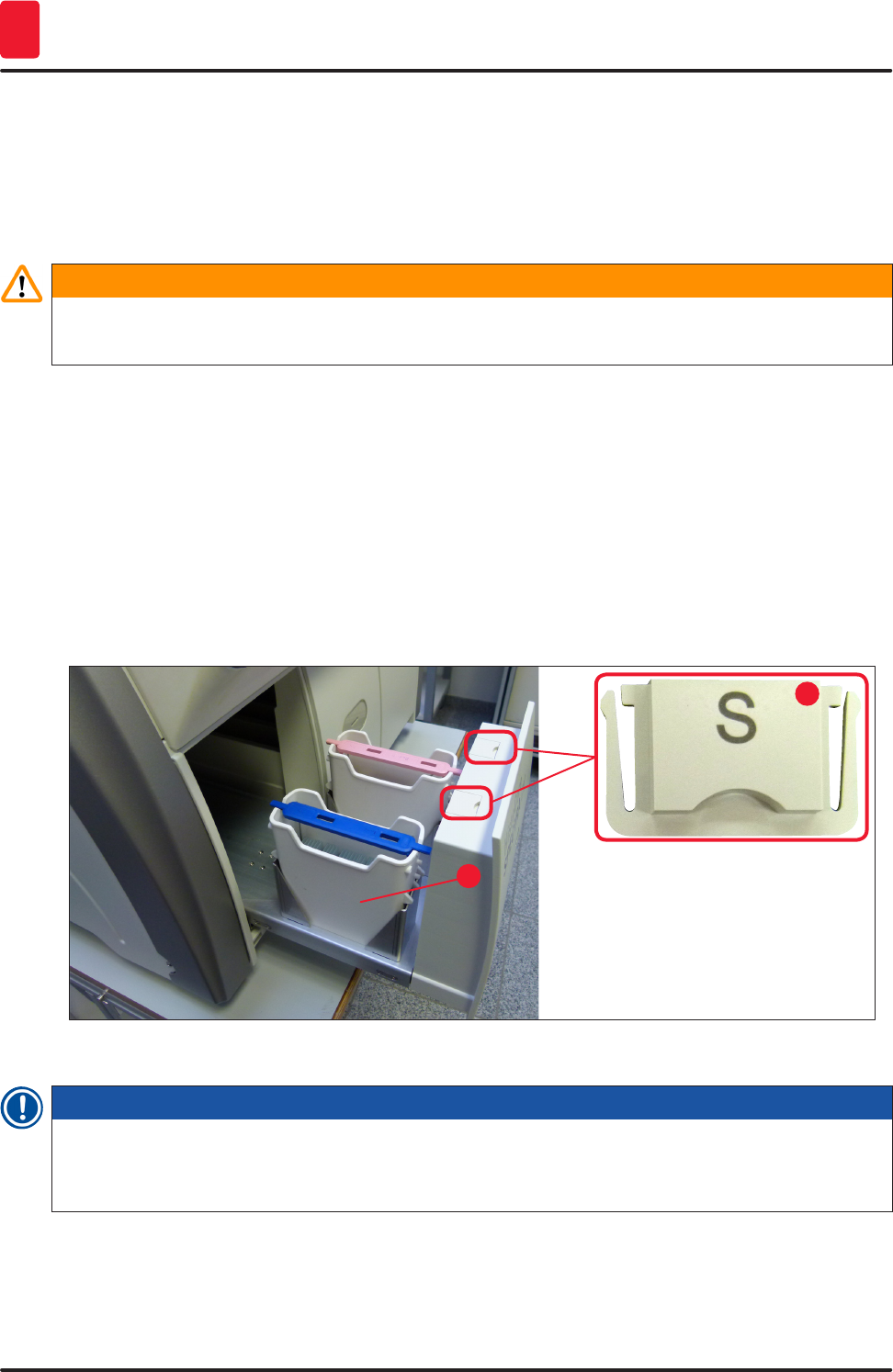
1. Remove reagent vessels (→ Fig. 83-1) from the load drawer and store them outside the
instrument.
2. Check the solvent in the reagent vessels, correct the level or replace the solvent if necessary
(→ P. 33 – 4.6 Refilling consumables).
3. Check the inside of the load drawer for reagent residue and clean up any you find (→ P. 111 –
7.2.4 Interior cleaning).
4. Finally, insert the reagent vessels into the correct positions again.
LObserve the existing labeling (→ Fig. 83-2) for stations in the drawers.
1
2
Fig. 83
Note
Reagent residue can also be present in the unload drawer from transporting the racks from the
coverslip line to the oven. Therefore, check the inside of the unload drawer for reagent residue and
clean if necessary (→ P. 111 – 7.2.4 Interior cleaning).
111
HistoCore SPECTRA CV
Cleaning and Maintenance 7
7.2.4 Interior cleaning
Warning
• There is a danger of cutting injuries during this cleaning step. Therefore, proceed with the
necessary caution and wear cut-resistant gloves (→ P. 19 – 3.1 Standard delivery – packing
list)!
• The warning messages in (→ P. 33 – 4.6 Refilling consumables) must be observed when
handling solvents!
1. Open the input and unload drawers and check the interior space behind the drawers for
broken glass and residual mountant.
Note
Remove all existing racks in the input and unload drawers before cleaning (→ Fig. 84).
Fig. 84
2. Carefully remove any dirt remnants.
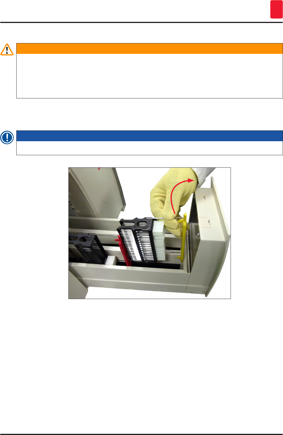
3. Pull the retaining lever for the unload drawer (→ Fig. 85-1) upwards while slowly continuing to
open the drawer as far as it will move.
112 Version 1.2, Revision A
Cleaning and Maintenance
7
1
Fig. 85
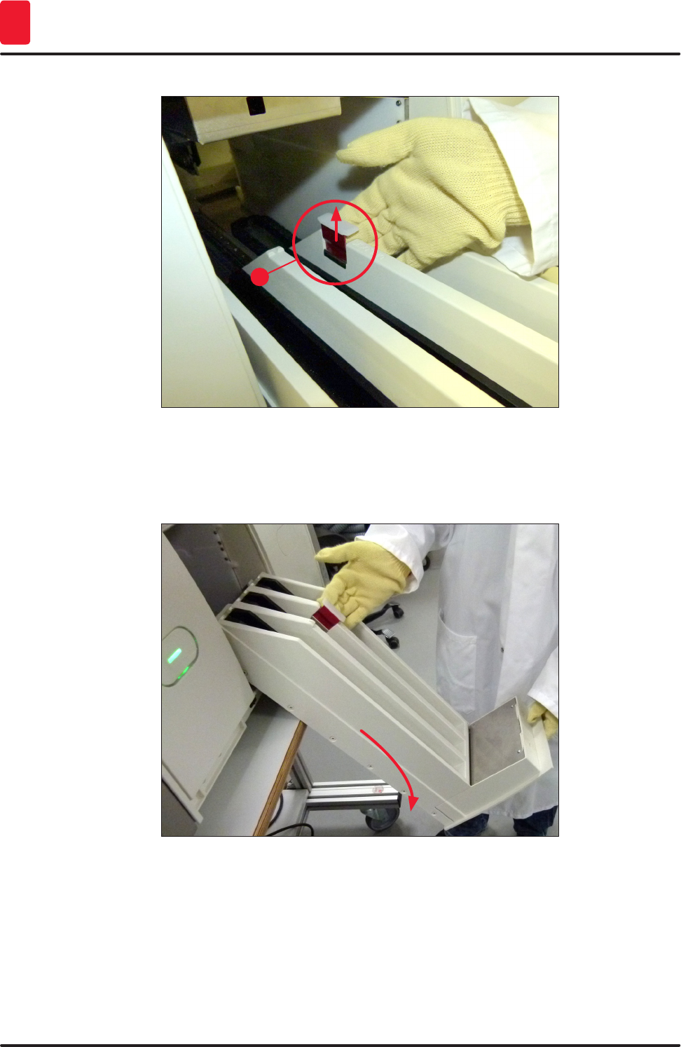
4. Carefully fold the unload drawer down and support it with one hand to allow you to clean the
rear area inside the instrument (→ Fig. 86).
Fig. 86
5. Soak a lint-free cloth with a compatible solvent and remove any mounting medium residue that
may be present. You can use a commercially available vacuum cleaner to pick up any non-
adhesive glass shards, splinters or dust.
6. Finally level the unload drawer again and move it in the instrument.
113
HistoCore SPECTRA CV
Cleaning and Maintenance 7
7.2.5 Cleaning the prime bottle
» Check the prime bottle for dried-out residual mountant and clean it with xylene if necessary. To
prevent delays, keep a replacement prime bottle ready and insert it into the position provided for
it in the instrument.
7.2.6 Cleaning the cannulas for the mounting medium bottle
» While changing a mounting medium bottle, check the cannula for dried mounting medium
residue and contamination and, if necessary, moisten with a compatible solvent and clean with a
lint-free cloth.
Note
There is a filter inserted in the cannula that prevents contamination from getting inside the internal
hose system. This filter is replaced every two years by a Leica service technician as part of annual
maintenance.
7.2.7 Cleaning the needle
1. Select the Module Status (→ P. 74 – 5.11 Module status) menu in the main menu and press
the Prime/Clean button in the desired coverslip line.
2. The needle moves automatically to the maintenance position.
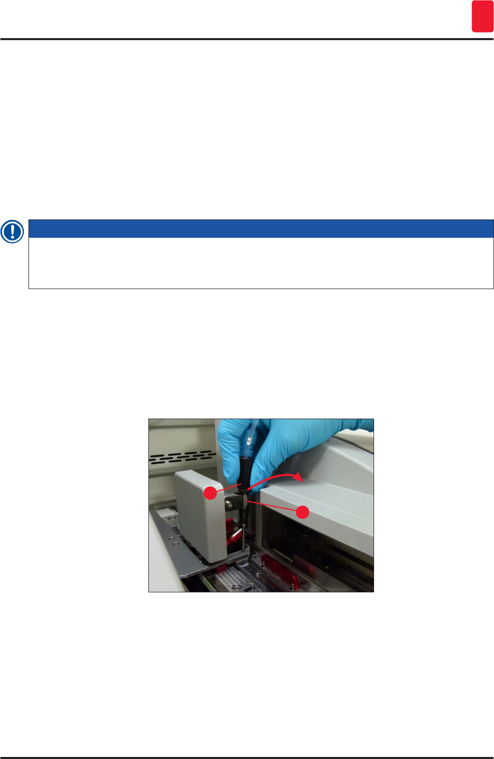
3. If the needle is heavily soiled (→ Fig. 87-1), remove it laterally from its holder (→ Fig. 87-2) and
hook it into a container filled with a compatible solvent. Let it soak shortly (approx. 10 min.).
Fig. 87
2
1
4. Then remove the needle from the solvent, moisten it with a compatible solvent and wipe off the
residual mountant with a soft, lint-free cloth.
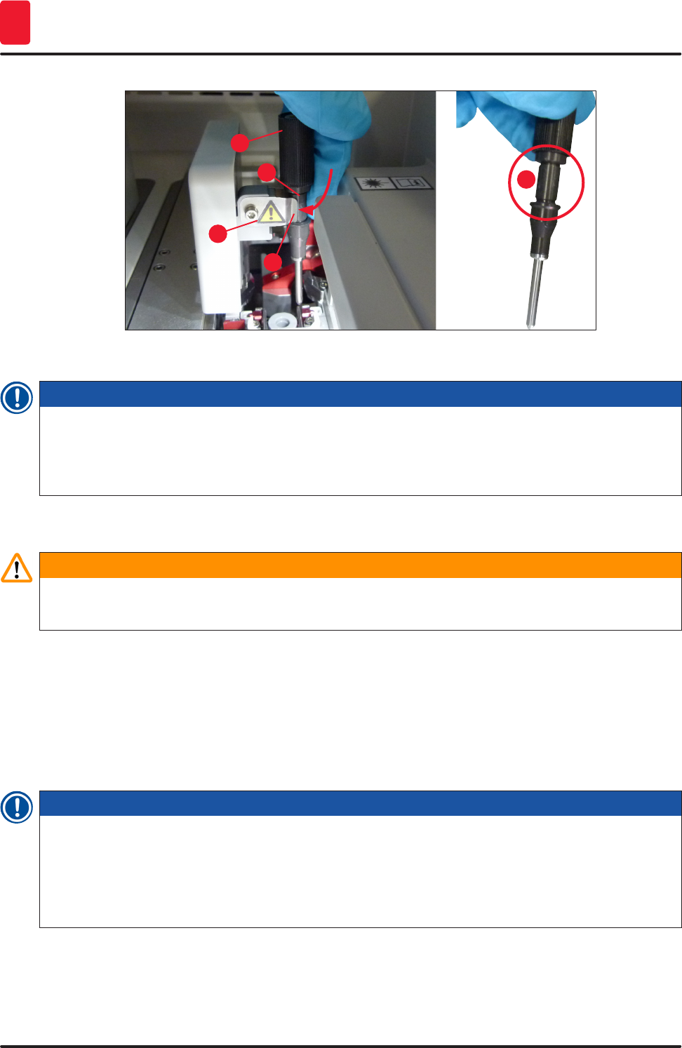
5. Finally, insert the needle (→ Fig. 88-1) back into its holder (→ Fig. 88-2).
114 Version 1.2, Revision A
Cleaning and Maintenance
7
2
4
3
1
3
Fig. 88
Note
The needle has a notch (→ Fig. 88-3) that fits exactly in the holder. The Attention symbol
(→ Fig. 88-4) on the holder (→ Fig. 88-2) indicates to the user that utmost care is required when
inserting the needle into the holder. The needle must be inserted straight and all the way in order to
make sure that no negative impact on the samples arises during processing.
Replace
Warning
• Only a Leica service technician may exchange a needle unit.
• An exchange of only the needle is not possible.
7.2.8 Filling and changing the needle cleaning container
• For handling the needle cleaning container, see (→ P. 82 – 6.3.2 Monitoring and refilling of the
needle cleaning container).
• To clean the glass cylinder (without cap), immerse it in a compatible solvent overnight to dissolve the
residual mountant.
Note
Replacement of a needle cleaning container:
• needle cleaning containers can be ordered (→ P. 155 – 9.1 Optional accessories) and be
replaced. We recommend always having a spare vessel ready so that the vessel in use can be
regularly cleaned with compatible solvent and routine operation can continue with the spare
vessel.
115
HistoCore SPECTRA CV
Cleaning and Maintenance 7
7.2.9 Removing the complete unit of the needle cleaning container
The needle cleaning container is inserted into a red complete unit (→ Fig. 89-1), which can be removed
by the user through the opening in the unload drawer. The complete unit is hooked into the coverslip
line by two lateral pins (→ Fig. 89-3). The removal may be necessary if the needle cleaning container
(→ Fig. 89-2) is stuck due to dried mounting medium and cannot be removed as described (→ P. 82 –
6.3.2 Monitoring and refilling of the needle cleaning container).
1
2
3
Fig. 89
Warning
• There is a danger of cutting injuries when removing the complete unit. Therefore, proceed with
the necessary level of caution and wear cut-resistant gloves (→ P. 19 – 3.1 Standard delivery –
packing list).
• The warning messages in (→ P. 33 – 4.6 Refilling consumables) must be observed when
handling solvents!
1. Open the hood.
2. Call up the Module Status and press the Prime/Clean button of the respective L1 or L2
coverslip line.
3. The needle moves upwards out of the needle cleaning container.
4. Remove the needle from the holder and insert it into the prime bottle.
5. Open the input and unload drawers completely and remove all racks.
116 Version 1.2, Revision A
Cleaning and Maintenance
7
Note
The unload drawer is capable of being unlocked and folded down so the user has easier access to
the interior of the instrument (→ P. 111 – 7.2.4 Interior cleaning). In doing so, make sure that the
inserts do not fall out into the unload drawer.
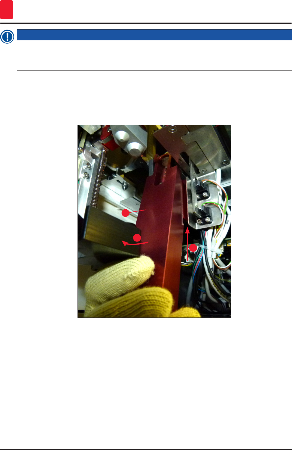
6. Carefully reach into the interior of the instrument through the slot in the unload drawer and feel
around the complete unit for the needle cleaning container (→ Fig. 90-1).
7. Grasp the complete unit from below and tilt it slightly in the direction of the back panel
(→ Fig. 90-2).
1
2
3
Fig. 90
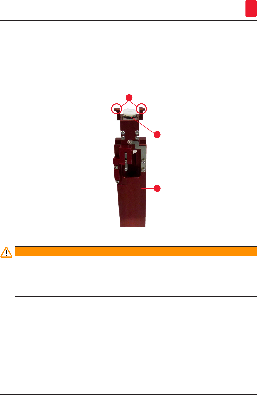
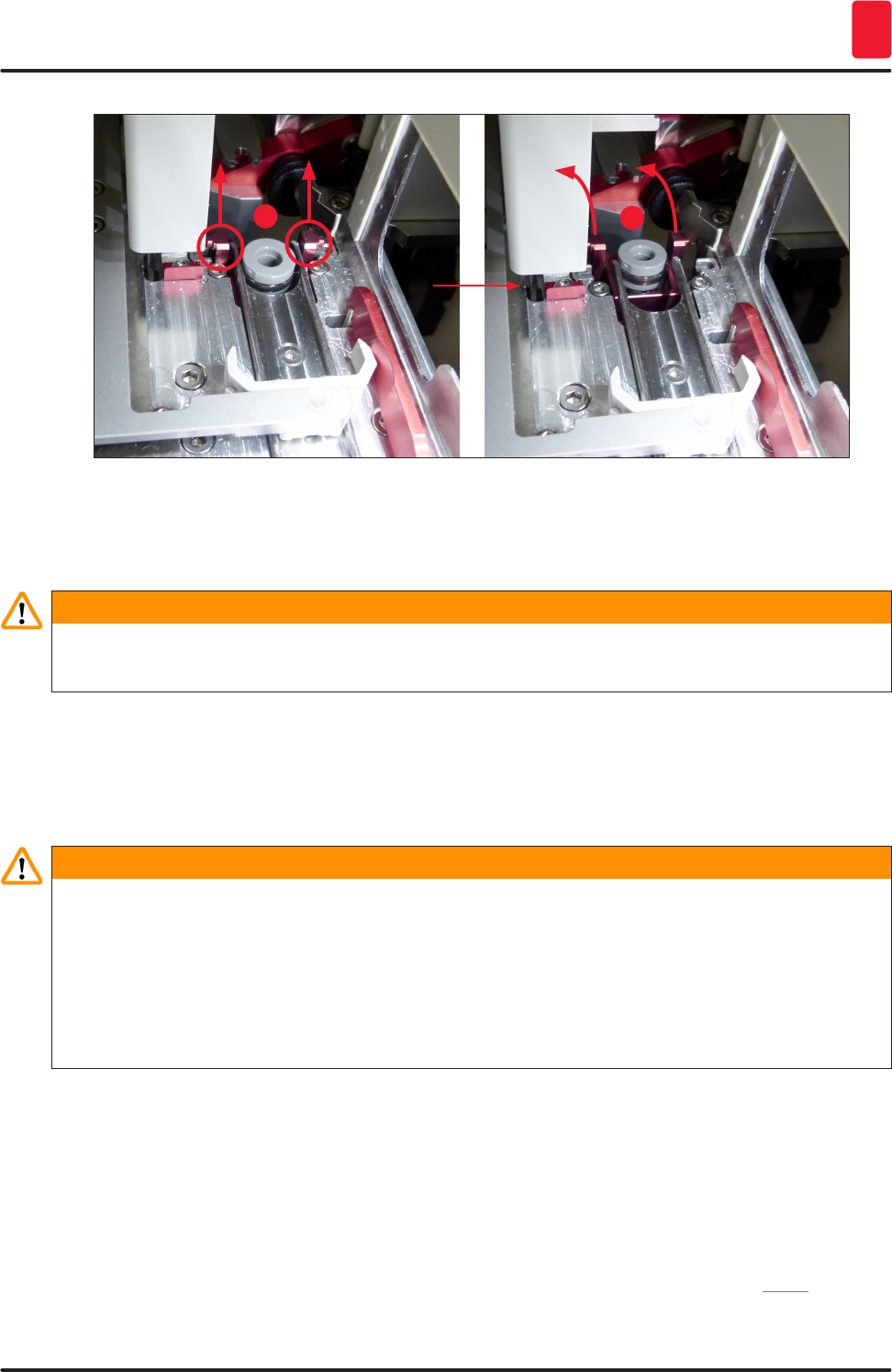
8. Then lift the complete unit (→ Fig. 90-3) so that the pins (→ Fig. 91-1) are lifted back over the
notches (→ Fig. 91-2).
117
HistoCore SPECTRA CV
Cleaning and Maintenance 7
12
Fig. 91
9. In the next step, guide the complete unit back and down and carefully remove it through the
slot in the unload drawer.
Warning
Remove the complete unit through the slot in the unload drawer, keeping it as upright as possible to
prevent solvent from running out of the needle cleaning container.
10. Position the complete unit with the attached needle cleaning container upside-down in a
container of sufficient size with solvent. Allow the solvent to take effect for approximately
10 minutes.
11. Then take the complete unit out of the solvent bath and let it drip off. Removing the needle
cleaning container should now be easy.
Warning
• The needle cleaning container is very fragile. If the needle cleaning container cannot be removed
after the solvent bath, the recommended course of action is to immerse the complete unit with the
container in solvent for a long period.
• In the meantime, insert the needle into a container with a compatible solvent to prevent the needle
from drying out.
• Please note that the coverslip line from which the complete unit was taken cannot be used during
this time.
12. Wipe the complete unit, glass cylinder and cap with a lint-free cloth that has been moistened
with solvent and dry.
13. Carefully insert the complete unit, without needle cleaning container, back into the correct
position inside the instrument.
14. Fill the needle cleaning container with solution while it is outside the instrument (→ P. 82 –
6.3.2 Monitoring and refilling of the needle cleaning container) and insert it into the complete
unit.
15. Insert the needle from the prime bottle back into the needle holder and press the Close button
in the Prime/Clean menu.
16. Finally, close the hood.
118 Version 1.2, Revision A
Cleaning and Maintenance
7
7.2.10 Cleaning the Pick&Place module
• For handling the Pick&Place module, see (→ P. 88 – 6.3.5 Inspect Pick&Place module).
Clean the following areas of the Pick&Place module with a lint-free cloth soaked with a compatible
solvent:
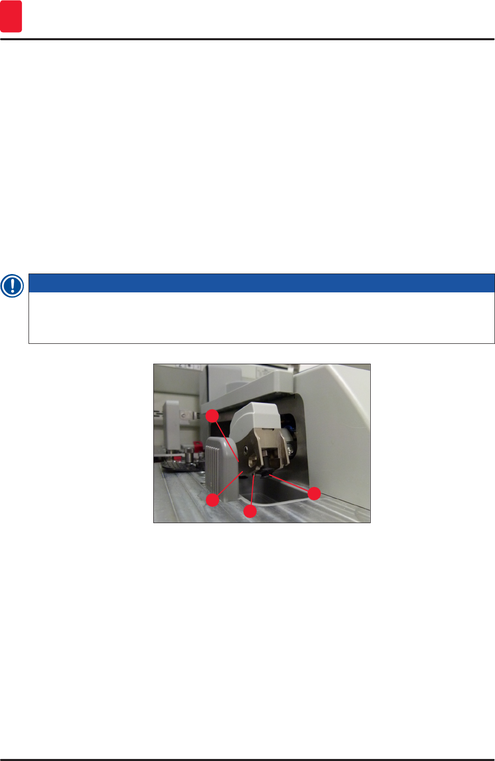
1. Check the front and rear suction cups (→ Fig. 92-2) at the Pick&Place module for dirt and
damages. Remove dirt with a lint-free cloth and a cloth soaked in a compatible solvent.
Deformed or damaged suction cups must be replaced (→ P. 118 – 7.2.11 Exchange suction
cups).
2. Carefully clean the skids (→ Fig. 92-1) on the left and right on the Pick&Place module from dirt.
3. Control the coverglass sensor pin (→ Fig. 92-3) for glued-on materials and mobility.
LDispose of glass shards, splinters and dust in accordance with laboratory specifications.
Note
At the bottom of the Pick&Place module is the coverglass sensor pin between both suction cups
(→ Fig. 92-3). The coverglass sensor pin can be moved freely if you can move it up and down by
touching it lightly with your fingertip.
1
2
3
2
Fig. 92
7.2.11 Exchange suction cups
1. Unplug the deformed and/or dirty suction cups from the Pick&Place module and dispose in
accordance with laboratory regulations.
2. Remove new suction cups from the package.
3. Attach the suction cups at the front (→ Fig. 93-2) and rear (→ Fig. 93-3) of the Pick&Place
module using a bent tweezers (→ Fig. 93-1).