Medtronic MiniMed 2007C Implantable Insulin Pump User Manual Dmp9196021 011 c
Medtronic MiniMed, Inc. Implantable Insulin Pump Dmp9196021 011 c
Contents
physician part1

1
Table of Contents
CHAPTER 1 Description of the Medtronic MiniMed 2007C
Implantable Insulin Pump System . . . . . . . . . . 11
Introduction . . . . . . . . . . . . . . . . . . . . . . . . . . . . . . . . . . . . . . . . . . . . . . . . . . . . . . .11
Implantable Insulin Pump . . . . . . . . . . . . . . . . . . . . . . . . . . . . . . . . . . . . . . . . . . . .13
Insulin medication . . . . . . . . . . . . . . . . . . . . . . . . . . . . . . . . . . . . . . . . . . . . . . .16
Side Port Catheter . . . . . . . . . . . . . . . . . . . . . . . . . . . . . . . . . . . . . . . . . . . . . . .16
Personal Pump Communicator (PPC) . . . . . . . . . . . . . . . . . . . . . . . . . . . . . . . .18
CHAPTER 2 Indications and Contraindications . . . . . . . . . . 21
Indications for use . . . . . . . . . . . . . . . . . . . . . . . . . . . . . . . . . . . . . . . . . . . . . . . . . .21
Contraindications for use . . . . . . . . . . . . . . . . . . . . . . . . . . . . . . . . . . . . . . . . . . . . .21
Possible adverse effects . . . . . . . . . . . . . . . . . . . . . . . . . . . . . . . . . . . . . . . . . . . . . .22
CHAPTER 3 Personal Pump Communicator (PPC) . . . . . . . 25
Introduction . . . . . . . . . . . . . . . . . . . . . . . . . . . . . . . . . . . . . . . . . . . . . . . . . . . . . . .25
PPC Icons . . . . . . . . . . . . . . . . . . . . . . . . . . . . . . . . . . . . . . . . . . . . . . . . . . . . . .26
PPC buttons . . . . . . . . . . . . . . . . . . . . . . . . . . . . . . . . . . . . . . . . . . . . . . . . . . . .27
Communicating with the pump . . . . . . . . . . . . . . . . . . . . . . . . . . . . . . . . . . . . .28
Dmp9196021-011_c.book Page 1 Thursday, April 4, 2002 8:15 AM

2
Install/Replace the main battery . . . . . . . . . . . . . . . . . . . . . . . . . . . . . . . . . . . .29
Part 1: PPC/Pump system initialization . . . . . . . . . . . . . . . . . . . . . . . . . . . . . . . . . .31
Initialize the PPC . . . . . . . . . . . . . . . . . . . . . . . . . . . . . . . . . . . . . . . . . . . . . . . .32
Set the time and date . . . . . . . . . . . . . . . . . . . . . . . . . . . . . . . . . . . . . . . . . . . . .34
Set alarms . . . . . . . . . . . . . . . . . . . . . . . . . . . . . . . . . . . . . . . . . . . . . . . . . . . . . .35
Set maximum bolus, basal rate and time display format . . . . . . . . . . . . . . .36
Lock maximum bolus/basal, enter personal ID and password, stop Pump .38
Program a basal rate . . . . . . . . . . . . . . . . . . . . . . . . . . . . . . . . . . . . . . . . . . . . . .40
Part 2: Additional PPC programming features . . . . . . . . . . . . . . . . . . . . . . . . . . . .42
Main menu . . . . . . . . . . . . . . . . . . . . . . . . . . . . . . . . . . . . . . . . . . . . . . . . . . . . .42
Program a bolus . . . . . . . . . . . . . . . . . . . . . . . . . . . . . . . . . . . . . . . . . . . . . .42
Set a normal bolus with the variable bolus feature turned off . . . . . . . . . . .42
Set a normal bolus with the variable bolus feature turned on . . . . . . . . . . .44
Set a square wave bolus . . . . . . . . . . . . . . . . . . . . . . . . . . . . . . . . . . . . . . . .45
Set a dual wave bolus . . . . . . . . . . . . . . . . . . . . . . . . . . . . . . . . . . . . . . . . . .47
Review bolus history . . . . . . . . . . . . . . . . . . . . . . . . . . . . . . . . . . . . . . . . . .49
Suspend mode . . . . . . . . . . . . . . . . . . . . . . . . . . . . . . . . . . . . . . . . . . . . . . .49
Programming a basal rate . . . . . . . . . . . . . . . . . . . . . . . . . . . . . . . . . . . . . .50
Programming basal delivery pattern . . . . . . . . . . . . . . . . . . . . . . . . . . . . . .50
Setting basal rate profiles in each delivery pattern . . . . . . . . . . . . . . . . . . .51
Program a temporary basal rate . . . . . . . . . . . . . . . . . . . . . . . . . . . . . . . . . .52
Set a temporary basal rate . . . . . . . . . . . . . . . . . . . . . . . . . . . . . . . . . . . . . .52
Stop a temporary basal rate . . . . . . . . . . . . . . . . . . . . . . . . . . . . . . . . . . . . .54
Personal events . . . . . . . . . . . . . . . . . . . . . . . . . . . . . . . . . . . . . . . . . . . . . .54
History . . . . . . . . . . . . . . . . . . . . . . . . . . . . . . . . . . . . . . . . . . . . . . . . . . . . .56
Setup Pump . . . . . . . . . . . . . . . . . . . . . . . . . . . . . . . . . . . . . . . . . . . . . . . . . . . . . . .58
Auto off . . . . . . . . . . . . . . . . . . . . . . . . . . . . . . . . . . . . . . . . . . . . . . . . . . . .58
Self test . . . . . . . . . . . . . . . . . . . . . . . . . . . . . . . . . . . . . . . . . . . . . . . . . . . .59
Initialize PPC to Pump . . . . . . . . . . . . . . . . . . . . . . . . . . . . . . . . . . . . . . . . .60
Setup II . . . . . . . . . . . . . . . . . . . . . . . . . . . . . . . . . . . . . . . . . . . . . . . . . . . . .60
Exit setup menu . . . . . . . . . . . . . . . . . . . . . . . . . . . . . . . . . . . . . . . . . . . . .60
Dmp9196021-011_c.book Page 2 Thursday, April 4, 2002 8:15 AM

3
Setup II . . . . . . . . . . . . . . . . . . . . . . . . . . . . . . . . . . . . . . . . . . . . . . . . . . . . . . . . . . .61
Audio bolus . . . . . . . . . . . . . . . . . . . . . . . . . . . . . . . . . . . . . . . . . . . . . . . . . . . .61
Activating the audio bolus feature . . . . . . . . . . . . . . . . . . . . . . . . . . . . . . . .61
Set an audio bolus from the main menu bolus screen . . . . . . . . . . . . . . . . .62
Variable bolus . . . . . . . . . . . . . . . . . . . . . . . . . . . . . . . . . . . . . . . . . . . . . . .62
Refill . . . . . . . . . . . . . . . . . . . . . . . . . . . . . . . . . . . . . . . . . . . . . . . . . . . . . .64
Priming . . . . . . . . . . . . . . . . . . . . . . . . . . . . . . . . . . . . . . . . . . . . . . . . . . . . .65
Diagnostic rate . . . . . . . . . . . . . . . . . . . . . . . . . . . . . . . . . . . . . . . . . . . . . . .67
Initialize to factory defaults . . . . . . . . . . . . . . . . . . . . . . . . . . . . . . . . . . . . .69
Download software . . . . . . . . . . . . . . . . . . . . . . . . . . . . . . . . . . . . . . . . . . .70
Stop Pump . . . . . . . . . . . . . . . . . . . . . . . . . . . . . . . . . . . . . . . . . . . . . . . . . .72
Supervisor password . . . . . . . . . . . . . . . . . . . . . . . . . . . . . . . . . . . . . . . . . .72
Exit supervisor . . . . . . . . . . . . . . . . . . . . . . . . . . . . . . . . . . . . . . . . . . . . . . .73
Personal Pump communicator messages . . . . . . . . . . . . . . . . . . . . . . . . . . .73
Clinical history codes . . . . . . . . . . . . . . . . . . . . . . . . . . . . . . . . . . . . . . . . . .75
Clinical history pump codes . . . . . . . . . . . . . . . . . . . . . . . . . . . . . . . . . . . .75
CHAPTER 4 Pump Implantation . . . . . . . . . . . . . . . . . . . . . . 77
Preprogramming and pre-testing the pump . . . . . . . . . . . . . . . . . . . . . . . . . . . . . . .77
Registration card . . . . . . . . . . . . . . . . . . . . . . . . . . . . . . . . . . . . . . . . . . . . . . . .77
Supplies and solutions . . . . . . . . . . . . . . . . . . . . . . . . . . . . . . . . . . . . . . . . . . . .78
Emptying and filling the Pump . . . . . . . . . . . . . . . . . . . . . . . . . . . . . . . . . . . . .79
Remove shipping fluid from the Pump . . . . . . . . . . . . . . . . . . . . . . . . . . . . . . .80
Rinse the Pump with insulin (IN1) . . . . . . . . . . . . . . . . . . . . . . . . . . . . . . . . . .82
Fill the Pump with insulin . . . . . . . . . . . . . . . . . . . . . . . . . . . . . . . . . . . . . . . . .85
Measure stroke volume . . . . . . . . . . . . . . . . . . . . . . . . . . . . . . . . . . . . . . . . . . .86
Prepare the Side Port Catheter . . . . . . . . . . . . . . . . . . . . . . . . . . . . . . . . . . . . . .88
Performing the surgical procedure . . . . . . . . . . . . . . . . . . . . . . . . . . . . . . . . . . .93
Dmp9196021-011_c.book Page 3 Thursday, April 4, 2002 8:15 AM

4
Pre-operative evaluation . . . . . . . . . . . . . . . . . . . . . . . . . . . . . . . . . . . . . . .93
Formation of the pump pocket . . . . . . . . . . . . . . . . . . . . . . . . . . . . . . . . . . .93
Catheter placement . . . . . . . . . . . . . . . . . . . . . . . . . . . . . . . . . . . . . . . . . . .95
Post-operative management . . . . . . . . . . . . . . . . . . . . . . . . . . . . . . . . . . . . .95
Post-operative hospitalization . . . . . . . . . . . . . . . . . . . . . . . . . . . . . . . . . . .95
Post-operative x-rays . . . . . . . . . . . . . . . . . . . . . . . . . . . . . . . . . . . . . . . . . .96
CHAPTER 5 Pump Refill Procedure . . . . . . . . . . . . . . . . . . . 97
Introduction . . . . . . . . . . . . . . . . . . . . . . . . . . . . . . . . . . . . . . . . . . . . . . . . . . . . . . .97
Supplies and solutions . . . . . . . . . . . . . . . . . . . . . . . . . . . . . . . . . . . . . . . . . . . .98
Prepare for pump refill . . . . . . . . . . . . . . . . . . . . . . . . . . . . . . . . . . . . . . . . . . . .99
Perform the refill procedure . . . . . . . . . . . . . . . . . . . . . . . . . . . . . . . . . . . . . . . . . .100
Fill out the refill form . . . . . . . . . . . . . . . . . . . . . . . . . . . . . . . . . . . . . . . . . . .100
Label syringes . . . . . . . . . . . . . . . . . . . . . . . . . . . . . . . . . . . . . . . . . . . . . . . . .100
Prepare the refill syringe for emptying the Pump . . . . . . . . . . . . . . . . . . . . . .100
Prepare the refill syringe for filling the Pump . . . . . . . . . . . . . . . . . . . . . . . . .101
Empty the Pump . . . . . . . . . . . . . . . . . . . . . . . . . . . . . . . . . . . . . . . . . . . . . . . .102
Refill the Pump . . . . . . . . . . . . . . . . . . . . . . . . . . . . . . . . . . . . . . . . . . . . . . . .104
Calculate extracted and refill amounts . . . . . . . . . . . . . . . . . . . . . . . . . . . . . . .106
Calculate refill accuracy . . . . . . . . . . . . . . . . . . . . . . . . . . . . . . . . . . . . . . . . .106
CHAPTER 6 Explanting the Pump System . . . . . . . . . . . . . 107
Explant considerations . . . . . . . . . . . . . . . . . . . . . . . . . . . . . . . . . . . . . . . . . . . . . .107
Returning devices/components to MiniMed . . . . . . . . . . . . . . . . . . . . . . . . . . . . .107
Dmp9196021-011_c.book Page 4 Thursday, April 4, 2002 8:15 AM

5
CHAPTER 7 Warnings And Precautions . . . . . . . . . . . . . . . 109
Warnings . . . . . . . . . . . . . . . . . . . . . . . . . . . . . . . . . . . . . . . . . . . . . . . . . . . . . . . .109
Electrotherapy . . . . . . . . . . . . . . . . . . . . . . . . . . . . . . . . . . . . . . . . . . . . . . . . .109
Diagnostic ultrasound . . . . . . . . . . . . . . . . . . . . . . . . . . . . . . . . . . . . . . . . . . .110
Ultrasound therapy . . . . . . . . . . . . . . . . . . . . . . . . . . . . . . . . . . . . . . . . . . . . . .110
Diagnostic radiation . . . . . . . . . . . . . . . . . . . . . . . . . . . . . . . . . . . . . . . . . . . . .110
Therapeutic radiation . . . . . . . . . . . . . . . . . . . . . . . . . . . . . . . . . . . . . . . . . . . .110
Elevated anti-insulin antibodies . . . . . . . . . . . . . . . . . . . . . . . . . . . . . . . . . . . .111
Environmental conditions . . . . . . . . . . . . . . . . . . . . . . . . . . . . . . . . . . . . . . . .111
Sterilization . . . . . . . . . . . . . . . . . . . . . . . . . . . . . . . . . . . . . . . . . . . . . . . . . . .112
Precautions . . . . . . . . . . . . . . . . . . . . . . . . . . . . . . . . . . . . . . . . . . . . . . . . . . . . . . .113
Emergencies and the use of conventional insulin supplies . . . . . . . . . . . . . . .113
PPC reliability requirements . . . . . . . . . . . . . . . . . . . . . . . . . . . . . . . . . . . . . .113
Maximum dosages . . . . . . . . . . . . . . . . . . . . . . . . . . . . . . . . . . . . . . . . . . . . . .114
Electrical and magnetic fields . . . . . . . . . . . . . . . . . . . . . . . . . . . . . . . . . . . . .114
CHAPTER 8 Adverse Reactions. . . . . . . . . . . . . . . . . . . . . . 115
Adverse reactions . . . . . . . . . . . . . . . . . . . . . . . . . . . . . . . . . . . . . . . . . . . . . . . . . .115
Prevention . . . . . . . . . . . . . . . . . . . . . . . . . . . . . . . . . . . . . . . . . . . . . . . . . . . . . . .116
CHAPTER 9 System Alarms and Messages . . . . . . . . . . . . 117
Pump alarms . . . . . . . . . . . . . . . . . . . . . . . . . . . . . . . . . . . . . . . . . . . . . . . . . . . . .118
Alarm feedback . . . . . . . . . . . . . . . . . . . . . . . . . . . . . . . . . . . . . . . . . . . . . . . .118
Pump low battery . . . . . . . . . . . . . . . . . . . . . . . . . . . . . . . . . . . . . . . . . . . . . . .118
Depleted pump battery . . . . . . . . . . . . . . . . . . . . . . . . . . . . . . . . . . . . . . . . . . .119
Dmp9196021-011_c.book Page 5 Thursday, April 4, 2002 8:15 AM

6
System error . . . . . . . . . . . . . . . . . . . . . . . . . . . . . . . . . . . . . . . . . . . . . . . . . . .119
Pump self test fail . . . . . . . . . . . . . . . . . . . . . . . . . . . . . . . . . . . . . . . . . . . . . .120
PPC alarms . . . . . . . . . . . . . . . . . . . . . . . . . . . . . . . . . . . . . . . . . . . . . . . . . . . .120
PPC low battery . . . . . . . . . . . . . . . . . . . . . . . . . . . . . . . . . . . . . . . . . . . . . . . .120
PPC depleted battery . . . . . . . . . . . . . . . . . . . . . . . . . . . . . . . . . . . . . . . . . . . .121
PPC needs servicing . . . . . . . . . . . . . . . . . . . . . . . . . . . . . . . . . . . . . . . . . . . . .122
Low reservoir . . . . . . . . . . . . . . . . . . . . . . . . . . . . . . . . . . . . . . . . . . . . . . . . . .122
Empty reservoir . . . . . . . . . . . . . . . . . . . . . . . . . . . . . . . . . . . . . . . . . . . . . . . .122
Telemetry communication error . . . . . . . . . . . . . . . . . . . . . . . . . . . . . . . . . . . .123
Communication error during download . . . . . . . . . . . . . . . . . . . . . . . . . . . . . .123
Initialize alarm . . . . . . . . . . . . . . . . . . . . . . . . . . . . . . . . . . . . . . . . . . . . . . . . .124
PPC not initialized . . . . . . . . . . . . . . . . . . . . . . . . . . . . . . . . . . . . . . . . . . . . . .125
Battery replacement . . . . . . . . . . . . . . . . . . . . . . . . . . . . . . . . . . . . . . . . . . . . .125
Initialize to factory defaults . . . . . . . . . . . . . . . . . . . . . . . . . . . . . . . . . . . . . . .126
Pump stopped . . . . . . . . . . . . . . . . . . . . . . . . . . . . . . . . . . . . . . . . . . . . . . . . . .126
Pump suspended . . . . . . . . . . . . . . . . . . . . . . . . . . . . . . . . . . . . . . . . . . . . . . .126
Auto off . . . . . . . . . . . . . . . . . . . . . . . . . . . . . . . . . . . . . . . . . . . . . . . . . . . . . .127
Hourly maximum exceeded . . . . . . . . . . . . . . . . . . . . . . . . . . . . . . . . . . . . . . .127
Pump alarm table . . . . . . . . . . . . . . . . . . . . . . . . . . . . . . . . . . . . . . . . . . . . . . .128
CHAPTER 10 Troubleshooting Pump System Under-delivery 131
Diagnostic procedures . . . . . . . . . . . . . . . . . . . . . . . . . . . . . . . . . . . . . . . . . . .131
Under-delivery caused by backflow . . . . . . . . . . . . . . . . . . . . . . . . . . . . . . . .131
Under-delivery caused by catheter occlusion . . . . . . . . . . . . . . . . . . . . . . . . .132
Dmp9196021-011_c.book Page 6 Thursday, April 4, 2002 8:15 AM

7
CHAPTER 11 MiniMed 2007C Implantable Insulin
Pump System. . . . . . . . . . . . . . . . . . . . . . . . . . 133
Implantable Insulin Pump MMT-2007C . . . . . . . . . . . . . . . . . . . . . . . . . . . . .133
Personal pump communicator (PPC) model MMT-3150 . . . . . . . . . . . . . . . .134
Side Port Catheter . . . . . . . . . . . . . . . . . . . . . . . . . . . . . . . . . . . . . . . . . . . . . .135
APPENDIX A Label Information . . . . . . . . . . . . . . . . . . . . . . 137
Symbol dictionary . . . . . . . . . . . . . . . . . . . . . . . . . . . . . . . . . . . . . . . . . . . . . .137
Packaging . . . . . . . . . . . . . . . . . . . . . . . . . . . . . . . . . . . . . . . . . . . . . . . . . .138
Other Information . . . . . . . . . . . . . . . . . . . . . . . . . . . . . . . . . . . . . . . . . . .140
APPENDIX B Implant Worksheet . . . . . . . . . . . . . . . . . . . . . 141
Implant worksheet form . . . . . . . . . . . . . . . . . . . . . . . . . . . . . . . . . . . . . . .141
APPENDIX C Refill Form . . . . . . . . . . . . . . . . . . . . . . . . . . . 143
Pump refill data . . . . . . . . . . . . . . . . . . . . . . . . . . . . . . . . . . . . . . . . . . . . .143
APPENDIX D Precautions and General Procedures . . . . . . . 145
Special note and precautions . . . . . . . . . . . . . . . . . . . . . . . . . . . . . . . . . . . . . . . . .145
General procedures . . . . . . . . . . . . . . . . . . . . . . . . . . . . . . . . . . . . . . . . . . . . .146
Locating the pump fill port and the side port . . . . . . . . . . . . . . . . . . . . . . . . . .147
Accessing the pump inlet . . . . . . . . . . . . . . . . . . . . . . . . . . . . . . . . . . . . . .148
Venting the Minimed refill syringe (optional) . . . . . . . . . . . . . . . . . . . . . . . . .149
Dmp9196021-011_c.book Page 7 Thursday, April 4, 2002 8:15 AM

8
APPENDIX E Pump Rinse Procedure . . . . . . . . . . . . . . . . . . .151
Supplies and solutions . . . . . . . . . . . . . . . . . . . . . . . . . . . . . . . . . . . . . . . .151
Preparing for the procedure . . . . . . . . . . . . . . . . . . . . . . . . . . . . . . . . . . . . . . .153
Prepare syringes for emptying the Pump . . . . . . . . . . . . . . . . . . . . . . . . . .153
Prepare syringes for filling the Pump . . . . . . . . . . . . . . . . . . . . . . . . . . . .153
Program minimal basal rate . . . . . . . . . . . . . . . . . . . . . . . . . . . . . . . . . . . .153
Remove insulin from the Pump and fill with NaOH . . . . . . . . . . . . . . . . .154
Equilibrate and pull NaOH through system . . . . . . . . . . . . . . . . . . . . . . . .156
Remove NaOH and fill with rinse buffer . . . . . . . . . . . . . . . . . . . . . . . . . .157
Equilibrate and pull rinse buffer through system . . . . . . . . . . . . . . . . . . . .159
Remove rinse buffer and fill with insulin . . . . . . . . . . . . . . . . . . . . . . . . .159
Equilibrate and pull insulin through system . . . . . . . . . . . . . . . . . . . . . . .161
Remove guide needles and record fill amount . . . . . . . . . . . . . . . . . . . . . .162
Program new basal rate . . . . . . . . . . . . . . . . . . . . . . . . . . . . . . . . . . . . . . .162
APPENDIX F Side Port Catheter Flush Procedure . . . . . . . . .163
Supplies and solutions . . . . . . . . . . . . . . . . . . . . . . . . . . . . . . . . . . . . . . . . . . .163
Preparing for the procedure . . . . . . . . . . . . . . . . . . . . . . . . . . . . . . . . . . . .164
Record patient’s blood glucose . . . . . . . . . . . . . . . . . . . . . . . . . . . . . . . . .165
Prepare syringes for emptying the Pump . . . . . . . . . . . . . . . . . . . . . . . . . .165
Prepare syringes for filling the Pump . . . . . . . . . . . . . . . . . . . . . . . . . . . .165
Prepare syringe for flushing the Side Port Catheter . . . . . . . . . . . . . . . . .166
Flushing the Side Port Catheter . . . . . . . . . . . . . . . . . . . . . . . . . . . . . . . . .167
Program minimal basal rate . . . . . . . . . . . . . . . . . . . . . . . . . . . . . . . . . . . .167
Remove insulin and fill with rinse buffer . . . . . . . . . . . . . . . . . . . . . . . . .167
Equilibrate and pull rinse buffer through system . . . . . . . . . . . . . . . . . . . .169
Flush side port catheter . . . . . . . . . . . . . . . . . . . . . . . . . . . . . . . . . . . . . . .170
Remove rinse buffer and fill with insulin . . . . . . . . . . . . . . . . . . . . . . . . .170
Equilibrate and pull insulin through system . . . . . . . . . . . . . . . . . . . . . . .172
Remove guide needles and record refill amount . . . . . . . . . . . . . . . . . . . .173
Program new basal rate . . . . . . . . . . . . . . . . . . . . . . . . . . . . . . . . . . . . . . .174
Remove rinse buffer from catheter . . . . . . . . . . . . . . . . . . . . . . . . . . . . . .174
Dmp9196021-011_c.book Page 8 Thursday, April 4, 2002 8:15 AM

9
APPENDIX G Stroke Volume Measurement . . . . . . . . . . . . . .175
Supplies and solutions . . . . . . . . . . . . . . . . . . . . . . . . . . . . . . . . . . . . . . . . . . .175
Preparing for the procedure . . . . . . . . . . . . . . . . . . . . . . . . . . . . . . . . . . . .176
Record patient’s blood glucose . . . . . . . . . . . . . . . . . . . . . . . . . . . . . . . . .176
Measuring stroke volume . . . . . . . . . . . . . . . . . . . . . . . . . . . . . . . . . . . . . .177
Record patient’s blood glucose . . . . . . . . . . . . . . . . . . . . . . . . . . . . . . . . .179
APPENDIX H Pressure Measurement Using The Side Port
Catheter . . . . . . . . . . . . . . . . . . . . . . . . . . . . . . .181
Supplies and solutions . . . . . . . . . . . . . . . . . . . . . . . . . . . . . . . . . . . . . . . . . . .182
Preparing for the procedure . . . . . . . . . . . . . . . . . . . . . . . . . . . . . . . . . . . .183
Record patient’s blood glucose . . . . . . . . . . . . . . . . . . . . . . . . . . . . . . . . .184
Prepare syringes for emptying the pump . . . . . . . . . . . . . . . . . . . . . . . . . .184
Prepare syringes for filling the pump . . . . . . . . . . . . . . . . . . . . . . . . . . . .184
Prepare syringe for priming the test setup . . . . . . . . . . . . . . . . . . . . . . . . .184
Measuring pressure in the side port . . . . . . . . . . . . . . . . . . . . . . . . . . . . . .185
Program minimal basal rate . . . . . . . . . . . . . . . . . . . . . . . . . . . . . . . . . . . .185
Remove insulin and fill with rinse buffer . . . . . . . . . . . . . . . . . . . . . . . . .185
Equilibrate and pull rinse buffer through system . . . . . . . . . . . . . . . . . . . .186
Perform pressure test . . . . . . . . . . . . . . . . . . . . . . . . . . . . . . . . . . . . . . . . .187
Remove rinse buffer and fill with insulin . . . . . . . . . . . . . . . . . . . . . . . . .191
Equilibrate and pull insulin through system . . . . . . . . . . . . . . . . . . . . . . .192
Remove guide needles and record refill amount . . . . . . . . . . . . . . . . . . . .194
Dmp9196021-011_c.book Page 9 Thursday, April 4, 2002 8:15 AM

10
Dmp9196021-011_c.book Page 10 Thursday, April 4, 2002 8:15 AM

11
CHAPTER 1 Description of the Medtronic
MiniMed 2007C Implantable
Insulin Pump System
Introduction
The Medtronic MiniMed 2007C Implantable Insulin Pump System brings
together sophisticated new technologies to provide continuous intraperi-
toneal insulin therapy for patients with Insulin Dependent Diabetes Melli-
tus (IDDM). The development of the Medtronic MiniMed 2007C
Implantable Insulin Pump System is the result of years of cooperative
research and development between MiniMed and:
The Johns Hopkins University, Applied Physics Laboratory.
U.S. National Aeronautics and Space Administration, Goddard Space
Flight Center. U.S. National Institutes of Health.
This manual is intended for use by the physician, surgeon, nurse specialist
and all other members of the healthcare team who care for patients with
the Medtronic MiniMed 2007C Implantable Insulin Pump System.
The Medtronic MiniMed 2007C Implantable Insulin Pump System uses
only special insulin formulations. The only insulin available today for use
in the Pump is HOE 21 PH U-400, manufactured by Aventis.
Dmp9196021-011_c.book Page 11 Thursday, April 4, 2002 8:15 AM
Description of the Medtronic MiniMed 2007C Implantable Insulin Pump System
12
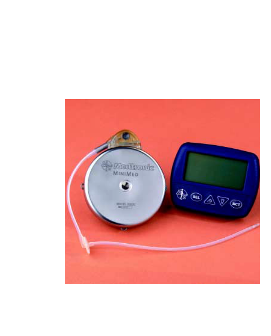
The system consists of three major components:
• Implantable Insulin Pump
• Side Port Catheter
• Personal Pump Communicator (PPC)
Each of these components, as well as system safety features, are discussed
in detail in the following sections.
Figure 1: Personal Pump Communicator (PPC) and Implantable
Insulin Pump
Dmp9196021-011_c.book Page 12 Thursday, April 4, 2002 8:15 AM
Implantable Insulin Pump 13
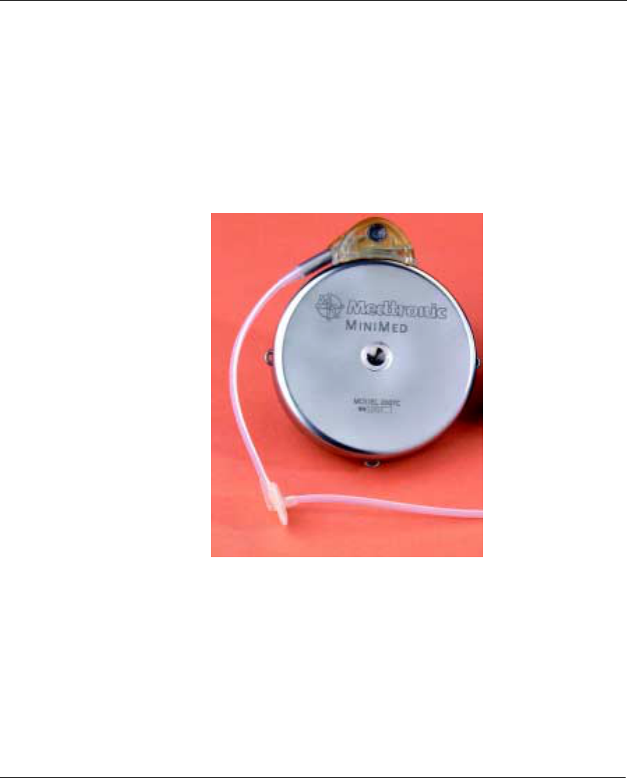
Implantable Insulin Pump
The Implantable Insulin Pump (Pump) is a round disc, 8.1 cm (3.2 inches)
in diameter, 2.0 cm (0.8 inches) thick. The Pump weighs 131 grams (4.6
ounces) when empty. The outside case of the Pump is made of titanium.
Titanium is a biocompatible metal used in many types of implantable
medical devices. A tangential Side Port Catheter is attached to the Pump
prior to implant, using a locking connector (see Figure 2).
Figure 2: The Implantable Insulin Pump
The Implantable Insulin Pump is an advanced insulin infusion device with
sophisticated microelectronics. It delivers a special insulin medication,
using a pulsatile solenoid pumping mechanism that is hermetically sealed
inside the biocompatible titanium case. Insulin delivery rates and profiles
are programmed using an external device, the Personal Pump Communi-
cator (PPC). Specific information on the Implantable Insulin Pump fea-
tures is outlined in the following sections.
Dmp9196021-011_c.book Page 13 Thursday, April 4, 2002 8:15 AM
Description of the Medtronic MiniMed 2007C Implantable Insulin Pump System
14
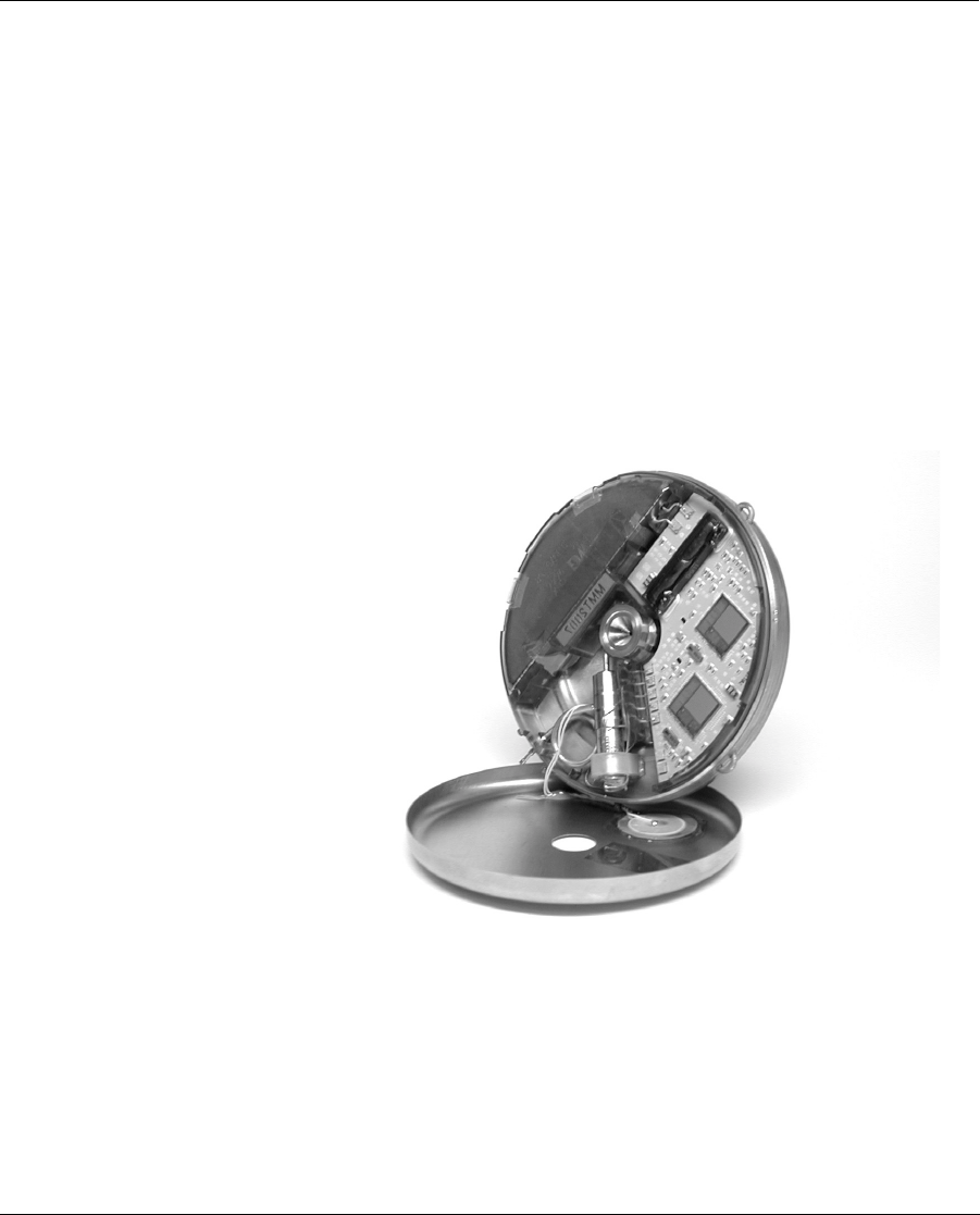
The Pump has six major components. These components are outlined
below:
• medication reservoir
• pumping mechanism
• microelectronics
• antenna
•battery
• tone transducer
Other components of the Pump include the inlet valve, fill port, septum,
Freon gas and 20µm filter. Figure 3 shows the interior components of the
Pump.
Figure 3: Interior of the Implantable Insulin Pump
Dmp9196021-011_c.book Page 14 Thursday, April 4, 2002 8:15 AM

Implantable Insulin Pump 15
The Medication Reservoir stores approximately 15 ml or 6,000 units of
a special U-400 insulin. Depending on an individual’s insulin require-
ments, the medication reservoir is refilled once in approximately every
two to three months. The medication reservoir is maintained at a negative
pressure (vacuum) at all times to allow for safe and reliable filling. This
vacuum prevents any risk of insulin leakage in the event of a breach in the
Pump case or reservoir. The reservoir is refilled with a special needle
(MiniMed Refill Needle MMT-4102). The fill port has a 20 micron filter
to prevent particulate material from entering the Pump and a redundant
septum and valve configuration to prevent entry of body fluids.
The Pumping Mechanism is a solenoid-operated, hermetically-welded
pulsatile system. The pumping mechanism is designed to seal automati-
cally to prevent leakage both into and out of the reservoir under physio-
logic temperatures and pressures. The mechanism is designed to provide
an insulin delivery accuracy of +10% from its labeled stroke volume.
Individual Pumps are calibrated to one of seventeen different stroke vol-
umes, ranging from 0.42 µL to 0.58 µL per stroke, in increments of
0.01 µL.
The Microelectronics act as the brain of the Pump. The microelectronics
contain two microprocessors which monitor and control all pump-stroke
activity. All commands delivered from the PPC via RF telemetry to the
Pump are then acknowledged back at the PPC. The Pump has a large
memory which stores Pump specifications and programming history.
The Antenna receives radiowaves from the PPC and delivers PPC pro-
gramming commands to the Pump microelectronics.
The Battery is a custom-made lithium carbon mono-fluoride power cell,
which supplies energy to the pumping mechanism and microelectronics.
It is similar to batteries used in pacemakers and is designed to provide 6 to
10 years of service, depending on the infusion rate (refer to pump specifi-
cations).
The Tone Transducer emits beeps to indicate certain alarm conditions.
These beeps are designed to be audible through the skin and can be set
with the PPC to one of two volumes. The Pump can also be programmed
to emit beeps that signal a programmed change in the medication delivery
rate.
Dmp9196021-011_c.book Page 15 Thursday, April 4, 2002 8:15 AM

Description of the Medtronic MiniMed 2007C Implantable Insulin Pump System
16
Radio-Opaque Identification the Implantable Insulin Pump features
radio-opaque identification. In the event of an emergency, the name
of the manufacturer and the Pump model number can be identified
with an x-ray.
Insulin medication
Only Aventis HOE 21 PH U-400 insulin can be used with the Medtronic
MiniMed 2007C Implantable Insulin Pump System.
HOE 21 PH U-400 is a highly purified, semi-synthetic human insulin
with 0.2% phenol as a preserving agent, glycerol as an isotonic compo-
nent, TRIS as a buffer, plus zinc and Genapol® as stabilizing agents.
HOE 21 PH U-400 is equivalent in mode of action to normal (soluble)
insulin. A special U-400 insulin concentration has been developed for use
in the Implantable Insulin Pump and is supplied in 10mL vials (400U/
mL) from Aventis.
Side Port Catheter
The Side Port Catheter (Catheter) transports insulin from the Pump into
an individual’s peritoneum where it is absorbed. The Catheter is made of
polyethylene-lined silicone rubber, which is biocompatible with subcuta-
neous and intraperitoneal tissues and supports the stability of the special
insulin. The Catheter is designed with two perpendicular sections: a
proximal subcutaneous section which attaches tangentially to the Pump
with a locking connector, and a distal section which is placed in the peri-
toneum (see Figure 4). To enable post-implant localization, a radioopaque
stripe runs the length of the Catheter.
Dmp9196021-011_c.book Page 16 Thursday, April 4, 2002 8:15 AM

Implantable Insulin Pump 17
Figure 4: The Intraperitoneal Catheter and Side Port
The Catheter side port is intended to provide access to the Catheter and
Pump outlet, in order to perform the non-surgical interventions and diag-
nostic procedures described in Appendices E, F and G. The side port
allows for the introduction of a needle and small syringe to clear Catheter
obstructions using pressures up to 100 psi. It also allows for the introduc-
tion of a needle to verify Pump stroke volume and permit non-surgical
diagnoses of Catheter blockages by direct pressure measurement.
Dmp9196021-011_c.book Page 17 Thursday, April 4, 2002 8:15 AM
Description of the Medtronic MiniMed 2007C Implantable Insulin Pump System
18
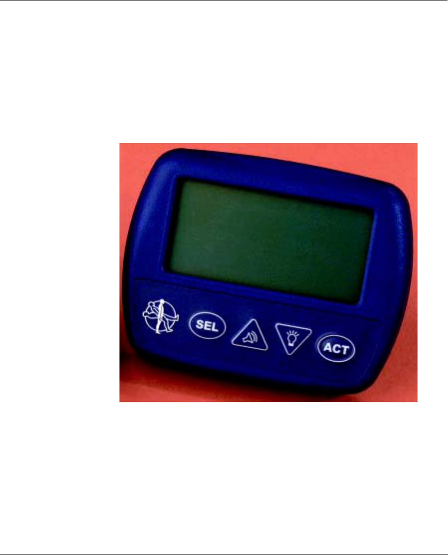
Personal Pump Communicator (PPC)
The Personal Pump Communicator (PPC) is the hand-held component of
the MiniMed 2007C Implantable Pump System (see Figure 5).
The PPC allows the physician and patient to communicate with the Pump
by transmitting radio frequency messages when the PPC is held within 3”
of the Pump. Additionally, the PPC stores important programming infor-
mation in its memory.
Figure 5: Personal Pump Communicator (PPC)
Dmp9196021-011_c.book Page 18 Thursday, April 4, 2002 8:15 AM

Implantable Insulin Pump 19
The PPC has been designed so the physician and patient can:
• Program basal infusion rates (48 basal rates, 3 different patterns)
• Deliver or suspend an immediate, square wave, or dual wave
bolus of insulin
• Deliver or cancel a temporary basal rate
• Review the delivery history
• Enter personal events (meal, snack, exercise)
Independent of the programming function, the PPC is able to receive and
record certain programming data from the Pump. The recorded informa-
tion is accessible and can be displayed on the screen.
Dmp9196021-011_c.book Page 19 Thursday, April 4, 2002 8:15 AM

Description of the Medtronic MiniMed 2007C Implantable Insulin Pump System
20
Dmp9196021-011_c.book Page 20 Thursday, April 4, 2002 8:15 AM

21
CHAPTER 2 Indications and
Contraindications
Indications for use
The Medtronic MiniMed 2007C Implantable Insulin Pump System is
indicated for intraperitoneal administration of exogenous insulin in
patients with diabetes mellitus.
Only Aventis HOE 21 PH U-400 insulin is indicated for use in the
Medtronic MiniMed 2007C Implantable Insulin Pump System.
Contraindications for use
The Medtronic MiniMed 2007C Implantable Insulin Pump System is con-
traindicated in patients who:
• are unwilling or unable to monitor their blood glucose level at
least four times per day.
• are unwilling or unable to make programming modifications to
the Pump based on glucose level readings.
• are unable or unwilling to administer insulin by other means, if
necessary.
• are unable or unwilling to comply with the guidance and advice
of their treating physician and other healthcare providers.
Dmp9196021-011_c.book Page 21 Thursday, April 4, 2002 8:15 AM

Indications and Contraindications
22
• reside at or travel (other than by pressurized commercial aircraft)
at elevations above 8,000 feet.
• have other medical or mental conditions which may place the
patient at risk.
• are unwilling or unable to return for routine insulin refills accord-
ing to their dosage requirements (approximately once every 2-3
months).
• present or have a history of sensitivity to titanium alloy,
polysulfone or silicone materials used in the implanted compo-
nents of the system.
Possible adverse effects
The MiniMed 2001 Implantable Insulin Pump System has undergone an
extensive clinical evaluation. The model 2007C is essentially identical to
the model 2001 Pump except for the use of updated electronics and bat-
tery. Evaluation of components used in the MiniMed 2001 System
spanned a period of ten years and involved approximately 650 patients
from both the U.S. and Europe. Although clinically relevant over-delivery
of insulin did not occur during the ten year evaluation period, there is a
potential for such an occurrence.
The following are specific adverse effects which should be understood by
the physician and explained to the patient. These do not include all
adverse effects which can occur with surgery in general or with the use of
this device, but are important considerations, particularly in the treatment
of diabetic patients. The general surgical risks, as well as operative site
cosmetic risks, should be explained to the patient prior to surgery.
Dmp9196021-011_c.book Page 22 Thursday, April 4, 2002 8:15 AM

Possible adverse effects 23
Abdominal Pain Foreign Body Reaction
Abnormal Healing Skin Disorder
Infection Urinary Disorder
Necrosis Psychiatric Decompensation
Retinal Disorder Skin Erosion
Abnormal Liver Function Kidney Disorder
Ileus Pocket Lymph Edema
Inflammation at Refill Site Pump Failure
Hyperglycemia Catheter Occlusion/Encapsulation
Hypoglycemia Battery Depletion
Ketoacidosis PPC Failure
Dmp9196021-011_c.book Page 23 Thursday, April 4, 2002 8:15 AM

Indications and Contraindications
24
Dmp9196021-011_c.book Page 24 Thursday, April 4, 2002 8:15 AM

25
CHAPTER 3 Personal Pump Communicator
(PPC)
Introduction
The Personal Pump Communicator (PPC) has a comprehensive set of pro-
gramming features to control the Implantable Insulin Pump in the treat-
ment of IDDM. The PPC cannot be used by the patient until it has been
initialized by the healthcare professional. This chapter of the manual is
divided in two parts:
The first part (Part 1) will describe the PPC/PUMP system initialization
process that will be performed the day prior to implant.
The second part (Part 2) will describe how to use the additional features
that the healthcare professional or patients can activate.
Dmp9196021-011_c.book Page 25 Thursday, April 4, 2002 8:15 AM
Personal Pump Communicator (PPC)
26
PPC Icons
After initialization, the PPC Main Screen displays the time (12hr. or 24hr.
format), month, day and a variety of icons. The type and purpose of these
icons are as follows:
Certain features of the PPC such as programming and dosing limits can be
set only by the healthcare professional in a password-protected mode
called the Supervisor Mode. Information pertaining to initializing the
PPC and entering the PPC Supervisor Mode is not included in the Patient
User Manual.
Bell Icon:
Displayed when the PPC receives a telemetry message from the Pump
indicating that the Pump has detected an alarm condition, when a PPC
error is detected and when the Pump is Suspended or Stopped.
Reservoir Level Indicator Icon:
The reservoir icon is composed of 4 segments that indicate how full
the Pump reservoir is, based on the history of Pump delivery.
Insulin Delivery Icon:
The PPC simulates spinning the delivery icon when insulin delivery is
in progress by displaying alternating patterns, the pattern changes
every 4 seconds. When the Pump is delivering a bolus, the pattern will
show three delivery segments. When the Pump is delivering a basal
rate, the pattern will show one delivery segment. When the Pump is
not delivering, all four segments will be displayed.
Dmp9196021-011_c.book Page 26 Thursday, April 4, 2002 8:15 AM

Introduction 27
PPC buttons
Select:SEL
Activate:
The SEL button steps through each of the displays and
menus.
ACT
Activate:
The ACT button activates programming changes in the
Pump, new information to be entered into the PPC mem-
ory, and alarms to be turned off. As a safety check, ACT
must be pressed to complete any programming changes.
A single beep is heard after activating a change.
Up and Down
Arrows:
▲
▲▲
▲ or ▼
▼▼
▼
The ▲
▲▲
▲ or ▼
▼▼
▼ arrows allow changes in the screen set-
tings. Pressing ▲
▲▲
▲ once will find the next highest set-
ting, and pressing ▼
▼▼
▼ once will find the next lowest
setting. Holding down either button will rapidly scroll
through the list of preset values. Desired values can then
be programmed by pressing ACT.
Sound Icon
the Up Arrow
When the Audio Bolus feature is turned on, pressing ▲
▲▲
▲
allows programming an Audio Bolus.
Light Icon
the Down
Arrow:
From the main operating screen, pressing ▼
▼▼
▼ once will
turn on the backlight. The backlight allows the Pump to
be programmed in the dark. The backlight will turn off
automatically after four seconds.
Dmp9196021-011_c.book Page 27 Thursday, April 4, 2002 8:15 AM

Personal Pump Communicator (PPC)
28
Communicating with the pump
Place the PPC near the Pump when the screen displays, “PPC COMMU-
NICATING.” The word "COMMUNICATING" will blink as indication of
succesfull communication. If a communication link between the PPC and
Pump is not established, a “TELEMETRY COMM ERROR 3” message
will appear. The PPC will beep six times once every minute until the
screen is acknowledged by pressing SEL and ACT. The screen will then
display “PPC COMMUNICATING” again.
After a communication is established between the PPC and Pump and
program information is successfully transferred to the Pump, the PPC will
beep once and return to the Time/Date screen.
• Always press the PPC buttons slowly and firmly. Wait until the
screen changes before pressing the button again.
• A flashing value on the screen means that the value is activated,
and can be changed by pressing the arrow buttons.
• The PPC cannot be turned off. Once the battery has been
installed, the PPC is on and remains on until the battery is
removed.
• Certain types of Radio Frequency (RF) generating equipment
could affect PPC communication with the Pump. If you are expe-
riencing communication difficulties, change locations.
• The time and date settings must be correct to ensure appropriate
calculation of insulin delivery and display of daily totals and
activity history.
Dmp9196021-011_c.book Page 28 Thursday, April 4, 2002 8:15 AM

Introduction 29
Install/Replace the main battery
The battery used to power the PPC is a 1.5v AA alkaline. The life of the
battery is approximately 8 weeks during normal usage conditions. If the
vibrator mode is selected, the battery life is approximately 6 weeks.
• Locate the battery door on the back of the PPC.
• Slide the locking bar to the left.
• Push the middle part of the PPC box (under the battery door) and
lift by gently pulling up the battery door to unlatch.
• Remove the old battery, noting the polarity. The screen will be
blank.
• Position the new battery so the + and - markings on the battery
match the polarity diagram in the battery compartment.
• Close the battery door.
• Slide the locking bar to the right.
• The PPC screen will reappear within 30 seconds:
1. The PPC will beep 6 times, and after a
few seconds, the screen will display
“CHECK PUMP STATUS”.
2. Press SEL then ACT, and place the PPC
near the Pump.
3. Wait a few seconds for the communica-
tion to complete.
PPC 4 102 100
PUMP __ __ __
08:26 JAN O2
CHECK
PUMP STATUS
PPC
COMMUNICATING
Dmp9196021-011_c.book Page 29 Thursday, April 4, 2002 8:15 AM

Personal Pump Communicator (PPC)
30
NOTE: When the PPC displays “PPC LOW BATTERY”,
the message can be cleared, and programming
continued. There should be sufficient energy in
the battery to communicate with the Pump a few
more times, but the battery should be changed as
soon as possible.
NOTE: If while programming the PPC, the screen goes
blank, the PPC beeps six times and then the
“CHECK PUMP STATUS” message appears, the
battery needs to be replaced.
Dmp9196021-011_c.book Page 30 Thursday, April 4, 2002 8:15 AM

Part 1: PPC/Pump system initialization 31
Part 1: PPC/Pump system initialization
The Implantable Insulin Pump arrives from MiniMed with preset factory
default values. During the initialization process these preset values are
downloaded into the PPC memory. The preset values can then be changed
by the healthcare professional, allowing the system to be personalized for
each patient. The factory default values are as follows:
Bolus Delivery Type Normal Off Locked
Maximum status Off
Maximum Bolus 25 U Password YIQ8
Audio Bolus Off Personal Events
status
OFF
Audio Feedback Disabled Personal ID 000
(32 characters)
Auto Off duration Off PPC alarm type High
Basal Delivery Pattern ARefill Amount 25 g
Maximum Basal Rate 35 U/H Time Format 12 hours
Insulin Concentration 400 U/ml Variable Bolus status Off
Dmp9196021-011_c.book Page 31 Thursday, April 4, 2002 8:15 AM

Personal Pump Communicator (PPC)
32
Initialize the PPC
When the healthcare professional receives a new PPC it must be “mar-
ried” to the Pump. Following are the basic steps used to initialize a Pump
System the day prior to implant:
1. The PPC is delivered without a battery in
place. After installing a new battery, the
PPC will beep six times and the screen
will identify the PPC software used (see
Chapter 1, Install/Replace the Main
Battery).
2. The screen now changes to, “PPC NOT
INITIALIZED”, and the PPC will beep six
times once every minute until the initial-
ization process is started. Press SEL and
then ACT, then quickly place the PPC
over the Pump.
3. When a communication link has been
established, the screen will read, “PPC
COMMUNICATING”, and then will
change to the next screen.
4. “NO” is blinking. Check to make sure the
serial number displayed on the screen
matches the Pump serial number. Press
either ▲
▲▲
▲ or ▼
▼▼
▼ once to change “NO” to
“YES” and then press ACT. Place the
PPC over the Pump.
5. The screen again reads “PPC COMMUNI-
CATING”, and the PPC will beep 3 times
at the end of the programming sequence.
During this process, the PPC receives all
of the factory preset values contained in
the Pump memory.
PUMP
PPC 4 162 100
__ __ __
PPC
NOT INITIALIZED
PPC
COMMUNICATING
INITIALIZING "NO"
PPC to PUMP
..................................
........................47568
COMMUNICATING
PPC
Dmp9196021-011_c.book Page 32 Thursday, April 4, 2002 8:15 AM

Part 1: PPC/Pump system initialization 33
6. The screen will read “PUMP SUS-
PENDED”. The Pump and PPC are
now “married”.
7. Press SEL, then ACT and place the PPC
near the Pump.
8. The screen now reads
“PUMP INITIALIZED”.
9. Press SEL and then ACT again, and the
PPC will display the Time/Date screen.
NOTE: When the alarm type is set to “VIBRATE” the
beeps from the PPC during normal programming
will be low volume.
PUMP SUSPENDED
PPC
COMMUNICATING
PUMP INITIALIZED
11:16 JAN O2
Dmp9196021-011_c.book Page 33 Thursday, April 4, 2002 8:15 AM

Personal Pump Communicator (PPC)
34
Set the time and date
The time and date settings must be correct to ensure accurate calculation
of insulin delivery, daily totals, and the proper display of insulin activity
history.
1. Press SEL until the “SETUP PUMP”
screen is displayed, then press ACT two
times. The first two digits of the time
(hours) will be flashing. Use the ▲
▲▲
▲ and ▼
▼▼
▼
buttons to select the correct hour, then
press ACT. The last two digits of the time
(minutes) will be flashing. Use the ▲
▲▲
▲ and ▼
▼▼
▼ buttons to select the cor-
rect minute, then press ACT. Repeat the programming process to
enter information for the year, month and day.
2. After completing the programming pro-
cess, quickly place the PPC near the
Pump. The PPC will display “PPC
COMMUNICATING” while transfer-
ring the time and date information to the
Pump. The PPC will then move to the
next screen, “AUTO-OFF.” Skip the “AUTO-OFF” screen by press-
ing SEL once to reach the next screen, “ALARMS”.
08:32 Jan 02
SET 2000
TIME-DATE
PPC
COMMUNICATING
Dmp9196021-011_c.book Page 34 Thursday, April 4, 2002 8:15 AM

Part 1: PPC/Pump system initialization 35
Set alarms
Alarms alert the user in the event the PPC or Pump recognizes an insulin
delivery problem. The Alarm Feedback screen must always be in the
“ON” position.
1. Press ACT to enter the “ALARMS”
menu.
2. The PPC has three alarm options, two
audible tones (Low/High) and a vibrate
mode. Press the ▲
▲▲
▲ and ▼
▼▼
▼ buttons to
select the desired alarm, then press ACT.
3. The screen will now display “SET
ALARM FEEDBACK”. This setting
should always be “ON”. Press ACT.
4. Place the PPC near the Pump. When the
communication is completed, the PPC
screen will change to “SELF TEST” and
then to the Time/Date screen.
NOTE: When the alarm type is set
to “vibrate” the beeps from the PPC during nor-
mal programming will be low volume.
ALARMS
SET
PPC
ALARM TYPE
LOW/HIGH/VIBRATE
SET
ALARM
FEEDBACK
ON/OFF
PPC
COMMUNICATING
Dmp9196021-011_c.book Page 35 Thursday, April 4, 2002 8:15 AM

Personal Pump Communicator (PPC)
36
Set maximum bolus, basal rate and time display format
This programming is performed in the “SETUP II” menus. These screens
allow healthcare professionals to limit the maximum amount of insulin a
patient can deliver, either when taking a bolus or setting a new basal rate.
Access to the “SETUP II” menus is through the “SETUP PUMP” screen.
1. Press SEL until the “SETUP PUMP”
screen is displayed. Press ACT and press
SEL to reach the “SETUP II” screen.
Press ACT and then SEL to reach the
“MAX BOLUS” screen.
2. Press ACT and the maximum bolus
amount (units) will start flashing. Press
the ▲
▲▲
▲ and ▼
▼▼
▼ buttons to change the maxi-
mum allowable bolus (0.0 to 25.0 units)
and then press ACT again.
3. Place the PPC near the Pump and com-
plete the communication process. The
PPC screen will automatically change to
the “MAX BASAL” screen.
4. Press ACT and the screen will change to
“SET MAX BASAL RATE”. The maxi-
mum basal amount will start flashing.
Press the ▲
▲▲
▲ and ▼
▼▼
▼ buttons to change the
maximum allowable basal rate (0.2 to
35.0 units/hour) and then press ACT
again.
5. Place the PPC near the Pump and com-
plete the communication process. The
PPC screen will automatically change to
“TIME FORMAT.”
MAX BOLUS
--
u
MAX BOLUS
--- -----
u
SET
PPC
COMMUNICATING
MAX BASAL RATE
0.2u/h
SET
PPC
COMMUNICATING
Dmp9196021-011_c.book Page 36 Thursday, April 4, 2002 8:15 AM

Part 1: PPC/Pump system initialization 37
6. Press ACT and the screen will change to
“SET TIME FORMAT.” Press the ▲
▲▲
▲ and
▼
▼▼
▼ buttons to select either a 12 hour (AM/
PM) or 24 hour (military time) format,
and then press ACT.
7. Place the PPC near the Pump and com-
plete the communication process. The
PPC screen will return to the “PER-
SONAL EVENTS” screen. Allow the
PPC to time out and return to the Time/
Date screen.
NOTE: Adding screens to the main menu, such as
“PERSONAL EVENTS” increases the number of
SEL button presses required to reach “SETUP
PUMP.”
SET
TIME FORMAT
12/24 HOUR
PPC
COMMUNICATING
Dmp9196021-011_c.book Page 37 Thursday, April 4, 2002 8:15 AM

Personal Pump Communicator (PPC)
38
Lock maximum bolus/basal, enter personal ID and password, stop
Pump
To access the Supervisor Mode press SEL until the “SETUP PUMP”
screen is displayed. Then press and hold down the ▲
▲▲
▲ and ▼
▼▼
▼ buttons
simultaneously until the “ENTER SUPERVISOR PASSWORD” screen
appears.
Patients should not be given the Supervisor
Mode password, to avoid the accidental
programming of a large priming bolus
(99.8 U) or diagnostic insulin rate.
1. The first zero will be flashing. Press the
▲
▲▲
▲ and ▼
▼▼
▼ buttons to select the first digit,
then press ACT.The screen advances to
the second zero. Press the ▲
▲▲
▲ and ▼
▼▼
▼ but-
tons to select the second digit, then press
ACT. Repeat for the last two digits. The
factory pre-set password is YIQ8.
2. Entry into the Supervisor Mode is indi-
cated by the screen “PUMP REFILL.”
3. Press SEL until the “SET MAXIMUMS
SCREEN” is displayed, and then ACT to
reach “SET MAXIMUMS”.
Press the ▲
▲▲
▲ and ▼
▼▼
▼ buttons to select
“ON” if the patient is not given access to
this feature, or “OFF” if the patient is per-
mitted access. Press ACT again.
!
WARNING
ENTER
SUPERVISOR
PASSWORD
0000
PUMP
REFILL
SET
MAXIMUMS OFF/ON
Dmp9196021-011_c.book Page 38 Thursday, April 4, 2002 8:15 AM

Part 1: PPC/Pump system initialization 39
4. Place the PPC near the Pump and com-
plete the communication process. The
PPC screen will automatically advance to
the “PERSONAL ID” screen. Press
ACT.
5. The first of the 32 possible ID locations is
flashing. Enter the patient ID (alpha-
numeric) by pressing the ▲
▲▲
▲ and ▼
▼▼
▼ but-
tons and then ACT after each entry. Con-
tinue to press ACT, activating each “0”
until the screen changes.
6. Place the PPC near the Pump and com-
plete the communication process.
7. Press SEL until the “SUPERVISOR
PASSWORD” screen is displayed. Then
press ACT.
8. The screen now reads, “SET SUPERVI-
SOR PASSWORD”. Press ACT. Use the
▲
▲▲
▲ and ▼
▼▼
▼ buttons to enter a new supervi-
sor password (alphanumeric), pressing
ACT after each entry.
NOTE: Record the password in the patient’s chart.
PPC
COMMUNICATING
SET PERSONAL ID
..................................
.................20KOLO5
PPC
COMMUNICATING
SET
SUPERVISOR
PASSWORD
Y1Q8
SET
SUPERVISOR
PASSWORD
0000
Dmp9196021-011_c.book Page 39 Thursday, April 4, 2002 8:15 AM

Personal Pump Communicator (PPC)
40
Program a basal rate
1. From the Time/Date screen, press SEL
until the “BASAL RATE” screen is dis-
played. Preset delivery pattern “A”, a
basal rate of 0.2 U/H, and the word
“NOW” is flashing. Press ACT.
2. A “1” now appears to the right of the “A”
indicating that this programming will
effect the 1st basal change within the “A”
pattern, (there are 3 patterns available
[A,B,C] and 48 basal changes possible
within each pattern). The flashing
0.2 U/H indicates the value can be changed. Use the ▲
▲▲
▲ and ▼
▼▼
▼ but-
tons to change the value and then press ACT.
NOTE: 00:00 indicates a start time of MIDNIGHT in
24hr. display mode. In 12hr. display mode, the
screen indicates the start time as 12:00am.
3. The screen now displays “SET TIME”,
and a time of 00:30 or 12:30 am (24 or 12
hour respectively) and a “2.”
If one basal is all that will be used, press
ACT two times. If more than one basal
rate is to be programmed, enter a start
time and amount of the new basal rate for that time period, then press
ACT and enter the new basal rate.
The user can enter a new basal rate at 30 minute intervals, up to 48
basal rates.
4. Place the PPC near the Pump and com-
plete the communication process.
08:26 OCT 12
BASAL RATE : A NOW
00:00 0.2u/h
-- U/H
00:30
SET RATE
BASAL RATE: A
PPC
COMMUNICATING
Dmp9196021-011_c.book Page 40 Thursday, April 4, 2002 8:15 AM

Part 1: PPC/Pump system initialization 41
5. The PPC will briefly display the calcu-
lated total basal dose for 24 hours, based
on the values and times entered in the
Basal Rate programming screen. In this
example, the total basal dose is
4.8 U/day.
24 HOUR TOTAL
4.8U
Dmp9196021-011_c.book Page 41 Thursday, April 4, 2002 8:15 AM

Personal Pump Communicator (PPC)
42
Part 2: Additional PPC programming features
Main menu
This second part will develop how to program the additional features that
the patient or the healthcare professional can activate.
Program a bolus
A properly initialized PPC is now ready to program a bolus.
The PPC/Pump allows you to set and deliver a bolus of insulin whenever
needed. The PPC has several special features which allow you to custom-
ize the programming and delivery of boluses.
• Normal Bolus and Audio Bolus
• Square Wave Bolus
• Dual Wave Bolus
NOTE: To use the Variable bolus programming options,
(e.g. square, dual), this option needs to be pro-
grammed “ON” in the SETUP II menu. If it is not
“ON” only the default bolus, “Normal bolus”,
will be available.
Set a normal bolus with the variable bolus feature turned off
1. From the Time/Date screen, press SEL.
The “BOLUS” screen is displayed, with
the time and date flashing.
2. Press ACT and the “SET BOLUS” screen
appears.The dashes under “IMM” are
flashing. Press the ▲
▲▲
▲ and ▼
▼▼
▼ buttons to
enter an immediate bolus amount.
08:13 Jan 02
BOLUS
PROG --
IMM EXT
10 U -- U
SET BOLUS
IMM
-- U
Dmp9196021-011_c.book Page 42 Thursday, April 4, 2002 8:15 AM

Part 2: Additional PPC programming features 43
3. Press ACT and the “CONFIRM” screen
is displayed, with the screen flashing.
Confirm the bolus amount by pressing
ACT again.
4. Place the PPC near the Pump and com-
plete the communication process.
5. When the bolus programming is com-
plete, the PPC will beep once and then
briefly display the amount of insulin cur-
rently delivered.
The Pump will beep at each of the first five strokes (if audio feedback is
ON). The PPC beeps and at the end of the bolus. Three segments of the
insulin delivery icon will be displayed and spinning slowly during the
bolus delivery. By pressing SEL you can read the amount of insulin deliv-
ered.
CONFIRM
IMM
2.6U
PPC
COMMUNICATING
BOLUS 0.0U
08:13 Jan 02
Dmp9196021-011_c.book Page 43 Thursday, April 4, 2002 8:15 AM

Personal Pump Communicator (PPC)
44
Set a normal bolus with the variable bolus feature turned on
1. From the Time/Date screen press SEL
until the “BOLUS” screen is displayed.
The last bolus value programmed and the
Time and Date will be flashing.
2. Press ACT and the “SET BOLUS TYPE”
screen appears. If “NORMAL” is not
flashing, use the ▲
▲▲
▲ and ▼
▼▼
▼ buttons to
select “NORMAL.” Press ACT.
3. The “SET BOLUS” screen appears, with
dashes under “IMM” flashing. Use the ▲
▲▲
▲
and ▼
▼▼
▼ buttons to enter an immediate
bolus amount.
4. Press ACT and the “CONFIRM” screen
is displayed, with the screen flashing.
Confirm the bolus amount by pressing
ACT again.
5. Place the PPC near the Pump and com-
plete the communication process.
6. When the bolus programming is com-
plete, the PPC will beep once and then
briefly display the amount of insulin cur-
rently delivered.
The Pump will beep at each of the first five strokes (if audio feedback is
ON). The PPC beeps at the end of the bolus. Three segments of the insulin
delivery icon will be displayed and spinning slowly during the bolus
delivery. By pressing SEL you can read the amount of insulin delivered.
08:13 Jan 02
BOLUS
IMM EXT
-- U -- U
SET
NORMAL
BOLUS TYPE
SET BOLUS
IMM
--- --- U
CONFIRM
IMM
2.6u
PPC
COMMUNICATING
08:23 JAN 04
0.0U
BOLUS
Dmp9196021-011_c.book Page 44 Thursday, April 4, 2002 8:15 AM

Part 2: Additional PPC programming features 45
Set a square wave bolus
A Square Wave Bolus of insulin is delivered evenly over a preset period
of time, from 30 minutes to 4 hours. A Square Wave Bolus may be desir-
able when eating long meals such as banquets or receptions, high fat
meals, or to compensate for gastroparesis. During a Square Wave Bolus,
the programmed basal rate is also delivered.
To access this feature you must first turn the Variable Bolus feature “ON”
in the “SETUP II” menu.
1. From the Time/Date screen, press SEL.
The “BOLUS” screen is displayed, show-
ing the last bolus programmed with the
time and date flashing.
2. Press ACT and the “SET BOLUS TYPE”
screen appears. Press the ▲
▲▲
▲ and ▼
▼▼
▼ but-
tons to select “SQUARE”. Press ACT.
3. The “BOLUS” screen appears, with
dashes under “EXT” flashing. Use the ▲
▲▲
▲
and ▼
▼▼
▼ buttons to enter an extended bolus
amount. Press ACT.
4. Blinking dashes will now appear under
the bolus amount entered.
Use the ▲
▲▲
▲ and ▼
▼▼
▼ buttons to enter a time
duration for the Square Wave Bolus, in
one-half hour increments from 30 min-
utes to four hours.
5. Press ACT and the “CONFIRM BOLUS”
screen is displayed, with the screen flash-
ing. Confirm the Square Wave Bolus by
pressing ACT again.
08:13 Jan 02
BOLUS
PROG --
IMM EXT
10 U -- U
SET
SQUARE
BOLUS TYPE
SET BOLUS
IMM EXT
-- U 4.0U
SET BOLUS
IMM EXT
-- U 4.0U
2:00
CONFIRM BOLUS
IMM EXT
-- U 4.0U
2:00
Dmp9196021-011_c.book Page 45 Thursday, April 4, 2002 8:15 AM

Personal Pump Communicator (PPC)
46
6. Place the PPC near the Pump and com-
plete the communication process.
7. When the bolus programming is com-
plete, the PPC will beep once and then
briefly display the amount of insulin cur-
rently delivered.
The Pump will beep at each of the first five strokes (if audio feedback is
ON). The PPC beeps at the end of the bolus. Three segments of the insulin
delivery icon will be displayed and spinning slowly during the bolus
delivery. By pressing SEL you can read the amount of insulin delivered.
PPC
COMMUNICATING
16:06 JAN 03
0.0U
BOLUS
Dmp9196021-011_c.book Page 46 Thursday, April 4, 2002 8:15 AM

Part 2: Additional PPC programming features 47
Set a dual wave bolus
The Dual Wave Bolus programs a Normal Bolus immediately followed
by a Square Wave Bolus.
To access this feature you must first turn the Variable Bolus feature ON in
the SETUP II menu.
1. From the Time/Date screen, press SEL.
The “BOLUS” screen is displayed, show-
ing the last bolus programmed with the
time and date flashing.
2. Press ACT and the “SET BOLUS TYPE”
screen appears. Press the ▲
▲▲
▲ and ▼
▼▼
▼ but-
tons to select “DUAL.” Press ACT.
3. The “BOLUS” screen appears, with
dashes under “IMM” flashing. Use the ▲
▲▲
▲
and ▼
▼▼
▼ buttons to enter the immediate
portion of the Dual Wave Bolus. Press
ACT.
4. The “BOLUS” screen now shows dashes
flashing under “EXT.”
Use the ▲
▲▲
▲ and ▼
▼▼
▼ buttons to enter the
extended portion of the Dual Wave
Bolus. Press ACT.
5. Blinking dashes will now appear under
the bolus amount entered.
Use the ▲
▲▲
▲ and ▼
▼▼
▼ buttons to enter a time
duration for the Square Wave Bolus, in
one-half hour increments from 30 min-
utes to four hours.
08:13 Jan 02
BOLUS
--- ---
IMM EXT
--- --- U ---- ---- U
SET
DUAL
BOLUS TYPE
SET BOLUS
IMM
2.0u
SET BOLUS
IMM EXT
2.0u 2.0u
SET BOLUS
IMM EXT
2.0u 2.0u
2:00
Dmp9196021-011_c.book Page 47 Thursday, April 4, 2002 8:15 AM

Personal Pump Communicator (PPC)
48
6. Press ACT and the “CONFIRM BOLUS”
screen is displayed, with the screen flash-
ing. Confirm the Dual Wave Bolus by
pressing ACT again.
7. Place the PPC over the pump and com-
plete the communication process.
8. When the bolus programming is com-
plete, the PPC will beep once and then
briefly display the amount of insulin cur-
rently delivered.
The pump will beep at each of the first five strokes (if audio feedback
is ON). The PPC beeps at the end of the bolus. Three segments of the
insulin delivery icon will be displayed and spinning slowly during the
bolus delivery. By pressing SEL, you can visualize the amount of
insulin delivered.
CONFIRM BOLUS
IMM EXT
2.0u 2.0u
2:00
PPC
COMMUNICATING
16:06 JAN 03
BOLUS
0.0u
Dmp9196021-011_c.book Page 48 Thursday, April 4, 2002 8:15 AM

Part 2: Additional PPC programming features 49
Review bolus history
To review the type, amount, time and day of your last 512 insulin boluses.
1. From the Time/Date screen, press SEL.
The “BOLUS” screen is displayed, show-
ing the last bolus programmed.
Use the ▲
▲▲
▲ and ▼
▼▼
▼ buttons to display pre-
vious boluses, along with the time and
day each bolus was delivered.
Suspend mode
The Suspend Pump mode allows the user to cancel a bolus delivery, while
still delivering a basal rate of 0.2 U/hr.
1. From the Time/Date screen, press SEL
until the “SUSPEND PUMP” screen is
displayed. Press ACT. The screen will
display a flashing “SUSPEND PUMP”
message. Press ACT again.
2. Place the PPC near the Pump and com-
plete the communication process.
3. When the communication is complete, the
Pump will beep 3 times and the PPC
screen will change to “PUMP SUS-
PENDED”. All four segments of the
insulin delivery icon are shown. The PPC
will beep every half-hour as long as the
Pump remains suspended.
NOTE: To restart the pump, press SEL. The “PUMP
SUSPENDED” screen will begin flashing. Then
press ACT.
08:23 Jan 02
BOLUS
--- ---
IMM EXT
---- U --- --- U
PROG
SUSPEND PUMP
PPC
COMMUNICATING
08:13 OCT 12
PUMP SUSPENDED
Dmp9196021-011_c.book Page 49 Thursday, April 4, 2002 8:15 AM

Personal Pump Communicator (PPC)
50
Programming a basal rate
Basic basal rate programming was described in earlier in this chapter.
This section describes additional basal rate options.
Programming basal delivery pattern
The PPC allows three basal delivery patterns. One such basal pattern
could be used for a working day, another for a weekend day, etc. Each of
the basal delivery patterns is a set of up to 48 basal rates, one for each
half-hour of the day. Pattern A is the factory pre-set. To access profiles B
or C you must enter the “SETUP I” screens.
1. Press SEL until the “PUMP SETUP”
screen is displayed. Press ACT. Press
SEL again to access the basal rate profile
screen, “DELIVERY PATTERN”.
2. Press ACT and the screen will change to
“SET DELIVERY PATTERN”. Use the
▲
▲▲
▲ and ▼
▼▼
▼ keys select the pattern pre-
ferred; A, B, or C. Each pattern can con-
tain up to 48 different basal rates. Press
ACT after choosing a pattern.
3. Place the PPC near the Pump and allow
the communication to complete.
NOTE: When the PPC times out, press SEL until the
“BASAL RATE” screen is displayed. The basal
pattern selected in SETUP II will now appear to
the right of “BASAL RATE” A, B, or C.
DELIVERY A
PATTERN
SET
DELIVERY A,B,C
PATTERN
PPC
COMMUNICATING
Dmp9196021-011_c.book Page 50 Thursday, April 4, 2002 8:15 AM

Part 2: Additional PPC programming features 51
Setting basal rate profiles in each delivery pattern
Each of the basal delivery patterns is a set of up to 48 basal rates, one for
each half-hour of the day.
1. Press SEL until the “BASAL RATE”
screen is displayed. A basal pattern is
selected (for example Pattern A). Press
ACT.
2. A “SET RATE” and “1” is now displayed
to the right of the “A” indicating this pro-
gramming will set the 1st basal rate
within the “A” profile. The “0.2U/H” is
now flashing, indicating the value can be
changed. Use the ▲
▲▲
▲ and ▼
▼▼
▼ arrow keys
to program a new value, for example “0.4 U/H”, and then press ACT.
NOTE: 00:00 indicates a start time of MIDNIGHT in 24hr.
display mode. 12:00am indicates a start time of
MIDNIGHT in 12hr. display mode.
3. The screen now displays “SET TIME”,
with a time of “00:30” or “12:30am”
flashing (24 or 12 hour respectively) and
a “2.” This screen allows the second basal
rate to be set. Enter a start time for the 2nd
basal rate within the “A” profile, for
example “04:30.” Press ACT. (Example: a second basal rate of 0.4U/
H starting at 04:30.)
4. This screen changes to “SET RATE”
again, indicating the 2nd basal rate can
now be programmed. Use the ▲
▲▲
▲ and ▼
▼▼
▼
arrow buttons to enter a new rate, for
example “0.2U/H”, and then press ACT.
BASAL RATE : A NOW
0.2U/H
00:00
BASAL RATE : A
0.2U/H
00:00
SET RATE
BASAL RATE : A 2
SET TIME
04:30 0.4u/h
BASAL RATE : 2
SET TIME
04:30 0.4u/h
Dmp9196021-011_c.book Page 51 Thursday, April 4, 2002 8:15 AM

Personal Pump Communicator (PPC)
52
5. A “3” now appears on the screen with
“SET TIME.” Follow the same procedure
previously described and program a new
profile. If no additional profiles are
needed change the flashing time to dashes
(by pressing ▼
▼▼
▼
) and press ACT.
6. The screen will indicate “PPC COMMU-
NICATING.” Place the PPC near the
Pump and complete the communication
process.
7. The screen will briefly display the calcu-
lated 24 hour basal dose based on the
basal rate programming. In this example
a total of “8.4U” will be delivered.
To set multiple basal profiles in the other pat-
terns (A,B,C), select the pattern in SETUP II menu and follow the same
procedure.
Program a temporary basal rate
A Temporary Basal Rate is often used when a brief change in basal deliv-
ery is required, for example during exercise.
Set a temporary basal rate
1. From the time and date display press SEL
until the “TEMPORARY BASAL”
screen is displayed.
2. Press ACT and the “SET DURATION”
screen appears. The time duration of the
Temporary Basal Rate is displayed as
flashing dashes. Press the ▲
▲▲
▲ and ▼
▼▼
▼ but-
tons to enter a time duration, in 30 minute
increments from 30 minutes to 24 hours.
BASAL RATE : 3
SET TIME
05:00 0.2u/h
PPC
COMMUNICATING
24 HOUR TOTAL
8.4u
TEMP BASAL
--- --- --- --- u/h
TEMP BASAL
--- --- u/h
00:30
SET DURATION
Dmp9196021-011_c.book Page 52 Thursday, April 4, 2002 8:15 AM

Part 2: Additional PPC programming features 53
3. Press ACT and “SET AMOUNT” screen
appears. The amount of the Temporary
Basal Rate is now flashing.
Press the ▲
▲▲
▲ and ▼
▼▼
▼ buttons to enter a
delivery amount. Press ACT again.
4. Place the PPC near the Pump and com-
plete the communication process.
5. When the communication is complete, the
Pump will beep once. The PPC screen
will briefly show the “TEMP BASAL”
screen before returning to the Time/Date
screen.
NOTE: When the Pump is delivering a Temporary Basal
rate, the first screen displayed when SEL is
pressed is “TEMP BASAL.” The PPC will also
beep every 30 minutes to alert the user that a
Temporary Basal rate is currently active.
TEMP BASAL
1.5u/h
00:30
SET AMOUNT
PPC
COMMUNICATING
TEMP BASAL
08:13 OCT 02
Dmp9196021-011_c.book Page 53 Thursday, April 4, 2002 8:15 AM

Personal Pump Communicator (PPC)
54
Stop a temporary basal rate
1. From the Time/Date screen press SEL
until the “TEMP BASAL” screen is dis-
played. Press ACT and the “SET DURA-
TION” appears, with the time duration
flashing. Press ▼
▼▼
▼ once until it resets to
dashes. Then press ACT.
2. Place the PPC near the Pump and com-
plete the communication process.
3. When the communication is complete, the
PPC will briefly return to the “TEMP
BASAL” screen with the amount dashes
flashing. Allow the PPC to return to the
Time/Date screen.
Personal events
This feature allows the user to enter event codes into the PPC memory,
and record the time and date of entry. Preset event codes are: 1 = meal, 2
= snack, 3 = sick and 4 = exercise. In addition, other event codes A, B and
C can be entered to record other important events. These other event
codes should be documented prior to their use.
To access the “EVENTS” screen in the main menu, “ON” must be acti-
vated in the “SETUP II” menu, “PERSONAL EVENTS” screen.
1. From the Time/Date screen, press SEL
until “SETUP PUMP” is displayed, then
press ACT.
Press SEL until “SETUP II” is displayed,
then press ACT.
Press SEL until “PERSONAL EVENTS”
is screen is displayed.
TEMP BASAL
--- --- 1.5u/h
SET DURATION
PPC
COMMUNICATING
TEMP BASAL
--- --- --- --- u/h
SET AMOUNT
OFF
PERSONAL
EVENTS
Dmp9196021-011_c.book Page 54 Thursday, April 4, 2002 8:15 AM

Part 2: Additional PPC programming features 55
2. Press ACT and “ON” or “OFF” begins
flashing.
3. Use the ▲
▲▲
▲ and ▼
▼▼
▼ buttons to select “ON”,
then press ACT again. The “PERSONAL
EVENTS” screen will now appear on the
main menu. Allow the PPC to return to
the Time/Date screen.
4. To set an event: From the Time/Date
screen press SEL until the “EVENT”
screen is displayed then press ACT.
The screen changes to “SET EVENT”
with the word “MEAL” flashing.
Use the ▲
▲▲
▲ and ▼
▼▼
▼ buttons to select the
desired event.
5. Press ACT and the current time will
appear flashing.
Use the ▲
▲▲
▲ and ▼
▼▼
▼ buttons to enter the
time the event occurred.
Press ACT when the proper time is dis-
played. Then allow the screen return to
Time/Date.
NOTE: Only historic or current event times can be
entered.
NOTE: If the Personal Events feature is turned “OFF” in
“SETUP II”, events cannot be entered into the
PPC.
EVENTS
PERSONAL ON/OFF
SET
PERSONAL ON/OFF
EVENTS
SET
EVENT
MEAL
SET TIME
EVENT
MEAL
07:32Am
Dmp9196021-011_c.book Page 55 Thursday, April 4, 2002 8:15 AM

Personal Pump Communicator (PPC)
56
History
Historical Pump data, such as insulin medication remaining, amount of
bolus and basal delivery since the last refill, etc., can be accessed and read
on the PPC.
1. From the Time/Date screen press SEL
until the “HISTORY” screen is dis-
played. Press ACT and the “READ
PUMP DATA” screen will appear flash-
ing.
Press ACT again.
2. Place the PPC near the Pump and com-
plete the communication process. The
PPC will acquire data from the Pump.
3. The screen will change to “MED
REMAINING”, indicating the estimated
amount of insulin medication remaining
in the Pump. Record this number if
required.
4. Press SEL and the screen will read
“INSULIN TOTAL.” Delivered amounts
of basal and bolus insulin medication are
displayed for the date flashing on the
screen. Use the ▲
▲▲
▲ and ▼
▼▼
▼ buttons to
review other daily totals.
5. Press SEL and the screen will change to
“CLINICAL HISTORY PPC”. Use the
▲
▲▲
▲ and ▼
▼▼
▼ buttons to review other PPC
events.
READ PUMP DATA
000000000000000000000000
000000000000000000010057
PPC
COMMUNICATING
MED REMAINING
2263 u
Jan 02
INSULIN TOTAL
BASAL BOLUS
9u 22u
6:16 Jan 02
CLINICAL HISTORY
11
PPC
Dmp9196021-011_c.book Page 56 Thursday, April 4, 2002 8:15 AM

Part 2: Additional PPC programming features 57
6. Press SEL and the screen will change to
“CLINICAL HISTORY PUMP”. Use the
▲
▲▲
▲ and ▼
▼▼
▼ buttons to review Pump events.
7. Press SEL and the screen will change to
“EST PUMP BATT”. This screen indi-
cates the Pump battery status, during no-
load (battery power is not used) and load
(extended communication sequence) con-
ditions. The Pump is set to alarm for low
battery when the loaded (LD) voltage is at or below 2.5 volts.
8. Press SEL and the screen will read
“EXIT HISTORY.” Press ACT. The PPC
will return to the Time/Date screen.
6:26 Jan 02
CLINICAL HISTORY
14
PUMP
Jan 02
EST PUMP BATTERY
2.9 V 2.7V
NO LD LD
EXIT HISTORY
Dmp9196021-011_c.book Page 57 Thursday, April 4, 2002 8:15 AM

Personal Pump Communicator (PPC)
58
Setup Pump
The “SETUP PUMP” screen permits access to the primary Setup menus
for the Pump. Setup features discussed previously in this chapter are ref-
erenced here. Other Setup features not previously discussed are presented
here. Press SEL until the “SETUP PUMP” screen is displayed, then press
ACT to access the SETUP menus.
Auto off
Auto Off is a safety feature, reminding the user to update insulin medica-
tion delivery programming in the Pump. An alarm can be set after a
period of programming inactivity, from one to 16 hours. At the onset of
the alarm the Pump will automatically be placed in SUSPEND mode.
1. From the “ SETUP PUMP” screen, press
ACT. Press SEL to reach the “AUTO
OFF” screen, then press ACT. The screen
will display “AUTO OFF” with flashing
dashes/time. Use the ▲
▲▲
▲ and ▼
▼▼
▼ buttons to
select the number of hours before an
“AUTO OFF” alarm occurs.
2. Press ACT. In this example, a time dura-
tion of 10 hours was selected. The PPC
will alarm if the user did not attempt to
program the Pump during the previous 10
hours and be placed in SUSPEND mode.
3. Place the PPC near the Pump and com-
plete the communication process.The
PPC will beep once and return to the
Time/Date screen.
AUTO OFF
--- --- HRS
SET
AUTO OFF
10 HRS
PPC
COMMUNICATING
Dmp9196021-011_c.book Page 58 Thursday, April 4, 2002 8:15 AM

Setup Pump 59
Self test
1. Self Test allows the user to perform a
diagnostic test of the Pump and PPC
operating system. Messages are relayed
between the PPC and Pump. From the
“SETUP PUMP” screen, press ACT.
Press SEL until the “SELF TEST” screen
is displayed. Press ACT.
2. Place the PPC near the Pump and com-
plete the communication process.
Verify that the following events occur:
• A series of tones will be heard from the Pump (4 beeps).
• An alarm tone will be heard from the PPC.
• The backlight on the PPC will turn on.
• The PPC screen will briefly activate all possible display icons,
numbers, etc.
• The PPC will vibrate.
NOTE: If the above test results do not occur or the screen
displays irregular characters, please notify
MiniMed. If the PPC displays the MiniMed logo
and software version, the PPC has restarted due
to a low battery. Replace the battery immediately.
If all electronics “pass” the Self Test, the screen will automatically
change to “PPC PASSED/PUMP PASSED.” After several seconds, the
screen will return to the Time/Date screen.
SELF TEST
PPC
COMMUNICATING
Dmp9196021-011_c.book Page 59 Thursday, April 4, 2002 8:15 AM

Personal Pump Communicator (PPC)
60
Initialize PPC to Pump
From the “SETUP PUMP” screen press ACT until “INITIALIZE PPC
TO PUMP” is displayed. This option “marries” the PPC to the Pump, and
it is used to initialize a new PPC. For initialization programming follow
the steps described in, Part 1: PPC/Pump sytem initialization.
Setup II
“SETUP II” permits access to an additional group of Setup menus for the
Pump. From the “SETUP PUMP” screen, press ACT until the “SETUP
II” screen is displayed. Setup II features are presented in the next section.
Exit setup menu
1. From the SETUP “pump” screen, press
SEL until the “EXIT SETUP MENU”
screen is displayed. Press ACT. The PPC
will return to the Time/Date screen.
EXIT SETUP MENU
Dmp9196021-011_c.book Page 60 Thursday, April 4, 2002 8:15 AM

Setup II 61
Setup II
Audio bolus
The Audio Bolus feature allows the user to deliver a bolus without look-
ing at the PPC screen. There are two Audio Bolus increments, 0.4U and
0.8U. With each press of the ▲
▲▲
▲ button, the PPC will beep one time (0.4U
setting) or two times (0.8U setting), depending on the delivery amount
selected per button press.
Activating the audio bolus feature
1. From the “SETUP II” screen, press ACT.
The “AUDIO BOLUS’ screen is shown.
2. Press ACT, and the screen changes to
“SET AUDIO BOLUS” with “OFF/ON”
flashing. Use the ▲
▲▲
▲ and ▼
▼▼
▼ buttons to
choose “ON” to activate the Audio Bolus
feature or “OFF” to disable it. Then press
ACT.
3. If “ON” was chosen, the “SET STEP
AUDIO BOLUS” appears with a step
value of 0.4U or 0.8U flashing on the
screen. Use the ▲
▲▲
▲ and ▼
▼▼
▼ buttons to
choose between a step rate of 0.4U or
0.8U. Press ACT. The Audio Bolus fea-
ture is now activated.
NOTE: If “OFF” is chosen, pressing the
▲
▲▲
▲
button will
have no effect.
AUDIO BOLUS
ON 0.4u
SET
ON
AUDIO BOLUS
0.4u
SET STEP
AUDIO BOLUS
0.4u
Dmp9196021-011_c.book Page 61 Thursday, April 4, 2002 8:15 AM

Personal Pump Communicator (PPC)
62
Set an audio bolus from the main menu bolus screen
1. From the Time/Date screen press the ▲
▲▲
▲
button. The PPC beeps either one or two
times, depending upon the audio bolus
step amount set. The user counts the
number of beeps to determine how much
insulin was programmed.
2. In this example the PPC was programmed
for a 0.8U increment, and the PPC beeps
two times for the 0.8U bolus.
Press ACT and the audio sequence
repeats to confirm the bolus amount.
Press ACT twice and the Pump will be
programmed. The PPC beeps once when the programming is com-
pleted. Place the PPC on the Pump to complete the communication
process.
NOTE: While an audio bolus is being delivered, the
▲
▲▲
▲
button will not function.
Variable bolus
To access the Variable Bolus feature enter “SETUP II” and press SEL
one time.
The screen will display “VARIABLE
BOLUS”. Press ACT.
The screen will now display “SET VARI-
ABLE BOLUS” and “ON or OFF” will be
flashing. Use the ▲
▲▲
▲
and ▼
▼▼
▼
buttons to select
“ON” or “OFF”, then Press ACT.
SET BOLUS
0.8U
IMM
PPC
COMMUNICATING
VARIABLE
BOLUS
ON
SET
VARIABLE
BOLUS
Dmp9196021-011_c.book Page 62 Thursday, April 4, 2002 8:15 AM

Setup II 63
Place the PPC near the Pump to complete
communication. If “ON” was chosen the
Variable Bolus option is now available in the
Main Menu/Bolus screen.
NOTE: If “OFF” is chosen, the-
Variable Bolus option (Square, Dual) will not be
available in the (Main Menu) Bolus screen.
PPC
COMMUNICATING
Dmp9196021-011_c.book Page 63 Thursday, April 4, 2002 8:15 AM

Personal Pump Communicator (PPC)
64
Refill
The refill procedure will be described in Chapter 5 “Pump Refill Proce-
dure.” The following screens are used at the end of this procedure, and
allow you to enter the new refill volume and to calculate the refill accu-
racy.
The "PUMP REFILL" screen appears when
you access the Supervisor Mode. Press ACT.
The PPC prompts for the residual amount of
insulin removed from the Pump. Use the ▲
▲▲
▲
and ▼
▼▼
▼ buttons to enter the weight (grams) of
extracted insulin.
Press ACT and the PPC prompts for the refill
insulin amount. Use the ▲
▲▲
▲ and ▼
▼▼
▼ buttons to
enter the weight (grams) of insulin refilled in
the Pump.
Press ACT. Confirm that the insulin concen-
tration defaults to U-400. Press ACT again.
Place the PPC near the Pump to complete the
process.
The calculated accuracy will be displayed
briefly. Record this value on the refill form.
PUMP REFILL
SET
EXTRACTED AMOUNT
---- ---- g
SET
REFILL AMOUNT
---- ---- g
SET
INSULIN U400
CONCENTRATION
PPC
COMMUNICATING
CALCULATED
ACCURACY
---- ---- %
Dmp9196021-011_c.book Page 64 Thursday, April 4, 2002 8:15 AM

Setup II 65
Priming
A priming bolus is not intended as a therapeu-
tic bolus. It should be only used when the
Pump is not implanted.
The Priming Bolus is used during the preparation of the Pump for implan-
tation. This feature “Primes” the Pump piston chamber, outlet port and
Catheter. The Pump will pulse approximately 500 times during this func-
tion. To access this feature, the Pump must be in “PUMP STOPPED”
mode.
1. From the “PUMP STOPPED” screen,
press SEL. The screen will begin flash-
ing.
2. Press the ▲
▲▲
▲ and ▼
▼▼
▼ buttons at the same
time until the “ENTER SUPERVISOR
PASSWORD” screen appears.
3. Re-enter the supervisor password, press-
ing ACT after each letter or number is
entered. The factory preset password is:
YIQ8. If the password has been changed,
enter the new password. When the Super-
visor Password is successfully entered,
the screen will change to “PUMP REFILL”. Press SEL until the
“PRIMING” screen appears.
4. Press ACT and “NO” appears flashing.
Press the ▲
▲▲
▲ and ▼
▼▼
▼ buttons to change to
“YES”, then press ACT.
!
WARNING
08:13 Oct 12
PUMP STOPPED
ENTER
SUPERVISOR
PASSWORD
YIQ8
PRIMING
PRIMING
PRIMING NO
99.8u
Dmp9196021-011_c.book Page 65 Thursday, April 4, 2002 8:15 AM

Personal Pump Communicator (PPC)
66
5. The word “CONFIRM” now appears.
Press ACT to activate the factory preset
priming bolus of 99.8U.
6. Place the PPC over the Pump and com-
plete the communication process.
7. The progress of the Priming Bolus can be
verified by pressing SEL. The Priming
Bolus takes approximately 10 minutes to
complete.
NOTE: The PPC will alarm every minute during the Prim-
ing Bolus. The Priming Bolus can be terminated
at any time by using the “SUSPEND PUMP” fea-
ture.
CONFIRM
PRIMING YES
99.8u
PPC
COMMUNICATING
08:13 OCT 12
PRIMING 0.0u
Dmp9196021-011_c.book Page 66 Thursday, April 4, 2002 8:15 AM

Setup II 67
Diagnostic rate
A diagnostic rate is intended for use only when
the Pump is filled with buffer.
The Diagnostic Rate feature is used to help “diagnose” Pump delivery
problems. Fill the Pump with rinse buffer before using this feature. To
access this feature, the Pump must be in the “PUMP STOPPED” mode.
1. From the “PUMP STOPPED” screen,
press SEL. The screen will begin flash-
ing.
2. Press the ▲
▲▲
▲ and ▼
▼▼
▼ buttons at the same
time until the “ENTER SUPERVISOR
PASSWORD” screen appears. Re-enter
the supervisor password, pressing ACT
after each letter or number is entered.
The factory preset password is: YIQ8.
3. When the Supervisor Password is suc-
cessfully entered, the screen will change
to “PUMP REFILL”. Press SEL until the
“DIAGNOSTIC RATE” screen appears.
4. Press ACT and the word “SET” appears
flashing. Use the ▲
▲▲
▲ and ▼
▼▼
▼ buttons to
enter a Diagnostic Rate (units/hour).
5. Press ACT and the word “SET” changes
to “DELIVER”. “NO” also appears
flashing. Use the ▲
▲▲
▲ and ▼
▼▼
▼ buttons
change “NO” to “YES”, then press ACT.
!
WARNING
08:13 OCT 12
PUMP STOPPED
0000
SET
SUPERVISOR
PASSWORD
--- --- u/h
DIAGNOSTIC
RATE
10 u/h
SET
DIAGNOSTIC
RATE
10 u/h
DELIVER
DIAGNOSTIC
RATE
Dmp9196021-011_c.book Page 67 Thursday, April 4, 2002 8:15 AM

Personal Pump Communicator (PPC)
68
6. The entire screen will be flashing. Press
ACT again to confirm the Diagnostic
Delivery Rate.
7. Place the PPC near the Pump and com-
plete the communication process.
8. The words “DIAGNOSTIC RATE”
appear briefly on the screen.The PPC
then returns to the Time/Date screen.
NOTE: Press SEL and the PPC will indicate “DIAGNOS-
TIC RATE.”
NOTE: Diagnostic Rate Delivery can be terminated at any
time by using the “SUSPEND PUMP” feature.
10 u/h
CONFIRM
DIAGNOSTIC
RATE
PPC
COMMUNICATING
08:13 OCT 12
DIAGNOSTIC RATE
Dmp9196021-011_c.book Page 68 Thursday, April 4, 2002 8:15 AM

Setup II 69
Initialize to factory defaults
This feature resets all programmed parameters in the Pump to preset fac-
tory default values. To access this feature, the Pump must be in the
“PUMP STOPPED” mode.
1. From the “PUMP STOPPED” screen,
press SEL. The screen will begin flash-
ing.
2. Press the ▲
▲▲
▲ and ▼
▼▼
▼ buttons at the same
time until the “ENTER SUPERVISOR
PASSWORD” screen appears. Reenter
the Supervisor Password, pressing ACT
after each letter or number is entered.
The factory preset password is: YIQ8.
3. When the Supervisor Password is suc-
cessfully entered, the screen will change
to “PUMP REFILL”. Press SEL until the
“INITIALIZE TO FACTORY
DEFAULTS” screen appears.
4. Press ACT and the word “CONFIRM”
will appear. Press ACT again to activate.
5. Place the PPC over the Pump and com-
plete the communication process.
6. The PPC will now read “PUMP SUS-
PENDED.” Press SEL then ACT.
08:13 oct 12
PUMP STOPPED
ENTER
PASSWORD
SUPERVISOR
0000
INITIALIZE
DEFAULTS
TO FACTORY
INITIALIZE
DEFAULTS
TO FACTORY
CONFIRM
PPC
COMMUNICATING
08:13 OCT 02
PUMP SUSPENDED
Dmp9196021-011_c.book Page 69 Thursday, April 4, 2002 8:15 AM

Personal Pump Communicator (PPC)
70
7. Place the PPC over the Pump and com-
plete the communication process.
8. The PPC now displays the “PUMP
RESET” screen, and beeps six times
every minute until the Pump is restarted.
Press SEL then ACT. The PPC returns
to the Time/Date screen. The Pump may
now be reprogrammed.
Download software
This feature has been disabled at the factory.
1. From the “PUMP REFILL” screen in the
Supervisor menu, press SEL until the
“DOWNLOAD SOFTWARE” screen
appears.
Stop Pump
This screen allows the Physician to stop the operation of the Pump.
From the “PUMP REFILL” screen in the
Supervisor Menu, press SEL until the “STOP
PUMP” screen appears.
Press ACT and the word “CONFIRM”
appears highlighted with the entire screen
flashing. Press ACT again to confirm.
PPC
COMMUNICATING
08:13 OCT 02
PUMP
RESET
DOWNLOAD
SOFTWARE
STOP PUMP
STOP PUMP
CONFIRM
Dmp9196021-011_c.book Page 70 Thursday, April 4, 2002 8:15 AM

Setup II 71
Place the PPC near the Pump and allow the
communication to complete.
The PPC will beep four times to confirm the
“STOP PUMP” command. To restart the
Pump, press SEL and “PUMP STOPPED”
will start to flash. Press ACT. Place the PPC
near the Pump. When the communication is
complete, the PPC returns to the Time/Date
screen.
Supervisor password
If the password is lost, access the Supervisor Menu as follows :
• Program the time to midnight (12:00 am or 00:00) and the date to
January 01.
• Enter the password 0000 within one minute. If the password is
not entered within one minute the time will be reset to midnight
again.
• Record the new password in the patient’s chart.
PPC
COMMUNICATING
08:13 OCT 02
PUMP STOPPED
Dmp9196021-011_c.book Page 71 Thursday, April 4, 2002 8:15 AM

Personal Pump Communicator (PPC)
72
Exit supervisor
To exit the Supervisor Programming Menu, press SEL until the “EXIT
SUPERVISOR” screen appears, then press ACT.
Personal Pump communicator messages
Display Screen Message Message Meaning or Action Required
AUTO OFF PUMP PUMP
SUSPENDED
Auto Off time interval has elapsed. Pump operation is
suspended.
BOLUS 0.0 u A bolus has been programmed and is being delivered.
CHECK PUMP
STATUS
The PPC battery has been replaced. The PPC needs to
check the Pump status.
LOW RESERVOIR The PPC has recognized the Pump has 800 units (2 ml)
or less insulin remaining in its reservoir. Schedule a
Pump refill as soon as possible. Allowing the reservoir
to completely empty may damage the Pump.
EMPTY RESERVOIR The PPC has recognized the Pump has 400 units (1 ml)
or less insulin remaining in its reservoir. Schedule a
Pump refill as soon as possible. Allowing the reservoir
to completely empty may damage the Pump.
HOURLY MAX
EXCEEDED
You attempt to deliver more than 2.5 times the bolus
maximum in one hour. To clear the message, press
SEL and ACT. You may exceed this limit by program-
ming another bolus within 10 minutes.
PPC NEEDS
SERVICING
The internal PPC backup battery is depleted. The PPC
can be programmed. Replace the PPC as soon as possi-
ble.
PPC LOW BATTERY The internal PPC backup battery is low. The PPC can
be programmed. Replace the PPC as soon as possible.
PPC DEPLETED
BATTERY
The PPC cannot be programmed. Replace the PPC AA
1.5 volt alkaline battery.
PPC NOT INITIALIZED The PPC has not been initialized to a Pump.
PPC LOW BATTERY The PPC can be programmed. Replace the PPC AA 1.5
volt alkaline battery.
PUMP LOW
BATTERY
The Pump battery energy is low but still functioning.
Schedule a replacement as soon as possible.
Dmp9196021-011_c.book Page 72 Thursday, April 4, 2002 8:15 AM

Setup II 73
PUMP INITIALIZED The PPC has been “married” to a Pump . Press SEL
and ACT.
PRIMING XX U A Priming Bolus has been programmed and is being
delivered.
PUMP RESET The Pump was reprogrammed to the preset factory val-
ues.
PUMP SELF TEST FAIL A Pump malfunction was detected during a Self Test.
Notify your physician immediately.
PUMP STOPPED The Pump is in stop mode.
PUMP STOPPED
1 or 2 or 3 or 4or 5 or 6
When the Pump recognizes a system malfunction, it
automatically stops and insulin delivery ceases. Notify
your physician immediately.
PUMP SUSPENDED The Pump is in suspend mode
PUMP ERROR
0 or 1
User attempts to initialize the PPC to a Pump that is not
compatible with it. Clear by pressing SEL and ACT.
Verify the personal ID of the Pump responding corre-
sponds to the personal ID entered into the PPC.
PUMP ERROR
40 or 41
The Pump has invalid data. The PPC will not initialize
to Pump.
TELEMETRY COMM
ERROR
3
The PPC and Pump are not communicating. Reposi-
tion the PPC over the Pump, then press SEL and ACT.
If the error message persists, contact MiniMed.
TELEMETRY COMM
ERROR
20
If the response is “NO” to the “INITIALIZE PPC TO
PUMP” until this screen appears. Move the PPC away
from any other Pump and perform the request again.
Display Screen Message Message Meaning or Action Required
Dmp9196021-011_c.book Page 73 Thursday, April 4, 2002 8:15 AM

Personal Pump Communicator (PPC)
74
Clinical history codes
In the “HISTORY” menu, the user can access clinical history from the
PPC and the Pump. Each number code corresponds to a particular event.
The following table lists each of the number codes with their correspond-
ing events.
Clinical history PPC/Pump codes
Clinical Event Code Clinical Event Code
Version Error 1 Time Out 2
No Response 3 Retry Packet 4
No Synchronization 5 Bad CRC 6
Invalid transmission 7 RX Overflow 8
Invalid Op code 9 TX Underflow 10
Bolus Total Error 13 Unknown IRQ Vector 12
Bad Duplicates 15 NMI Occurred 14
Stop Pump Alarm 17 Suspend Alarm 16
Prime Pump Alarm 19 Diagnostic Rate Alarm 18
Max Clock Stealer 21 Exclusion List Full 20
Non Initialized PPC 23 Min Clock Stealer 22
Pump Initialized 25 Pump Self Test Error 24
Pump Reset to Defaults 26
Dmp9196021-011_c.book Page 74 Thursday, April 4, 2002 8:15 AM

Setup II 75
Download Failure 27 Hourly Maximum 28
Refill Divide Error 29 Refill Invalid Calculation 30
Divide by 0 31 EEPROM Error 32
Bad EEPROM 33 Main Battery Low 34
Main Battery Depleted 35 Back-up Battery Low 36
Temporary Basal Rate 37 Check Pump Status 38
Download Complete 39 Invalid Concentration 40
Invalid Stroke Volume 41 Battery Removed 42
IP Communication Error 1 Charge Time Too Long 2
Post-Fire Voltage Reading
too High
3 Over-Delivery Error 4
Under-Delivery Error 5 Dead Battery 6
Auto Off Interval Exceeded 7 Low Reservoir 8
Empty Reservoir 9 Low Battery 10
Normal Delivery Mode 11 Stop Delivery Mode 12
Suspend Delivery Mode 13 Diagnostic Rate delivery
mode
14
Priming Bolus Delivery
Mode
15 Insulin Concentration
Change
16
Clinical Event Code Clinical Event Code
Dmp9196021-011_c.book Page 75 Thursday, April 4, 2002 8:15 AM

Personal Pump Communicator (PPC)
76
Dmp9196021-011_c.book Page 76 Thursday, April 4, 2002 8:15 AM

77
CHAPTER 4 Pump Implantation
Preprogramming and pre-testing the pump
Every Implantable Insulin Pump is fully tested before shipment and is
accompanied by a package insert indicating the measured stroke volume
and Pump type. Prior to shipping, each Pump is filled with sterile rinse
buffer to assure sterility.
Programming of the Pump may be performed a day before Pump implan-
tation. The Implantable Insulin Pump may be programmed through the
outer tray of the sterile package. First, the PPC needs to be “married” to
the Pump, then the Pump function is verified by performing the initializa-
tion procedure described in Chapter 3, PPC/Pump System Initialization.
Registration card
To ensure proper patient identification and device serial number tracking,
the Registration Card that accompanies each Pump must be completed
and promptly returned to MiniMed.
Dmp9196021-011_c.book Page 77 Thursday, April 4, 2002 8:15 AM

Pump Implantation
78
Supplies and solutions
Before preparing the Pump, be sure to read Appendix D, Precautions and
General Procedures. Assemble the necessary materials prior to starting
the procedure:
Supplies
• One (1) 100 µL sterile pipette (available non sterile from
MiniMed) MMT-4104
• One (1) sterile scalpel blade
• One (1) scale (0.01g resolution)
• One (1) sterile beaker (or sterile barrier towel) for weighing
• One (1) sterile bag for PPC
• One (1) Pump System: PPC, Pump and Side Port Catheter
• Sterile markers and Steri-Strips®
• Three (3) refill Kits - MMT-4105:
• 1 kit to remove shipping fluid from Pump
• 1 kit to fill the Pump with U-400 INSULIN (to rinse the
pump)
• 1 kit to fill the Pump with U-400 INSULIN (final insulin
fill)
• One (1) 3 mL syringe (fluid barrier)
• Three (3) MiniMed refill needles, MMT-4102
• Three (3) 18 gauge needles
• One (1) Implant Worksheet
• One (1) Back-up Pump System: PPC, Pump and Side Port Cathe-
ter
Solutions
• One (1) bottle of sterile water, room temperature
• One (1) vial 10 mL rinse buffer (RB)
• Four (4) vials 10 mL Aventis HOE 21 PH U-400 INSULIN
Dmp9196021-011_c.book Page 78 Thursday, April 4, 2002 8:15 AM

Preprogramming and pre-testing the pump 79
Emptying and filling the Pump
To prepare the Pump for implantation, the Pump must be emptied and
then filled twice and tested with insulin. These procedures are performed
in the operating room prior to implanting the patient. As this is a surgery,
all supplies and required equipment should be prepared in accordance
with the institution’s approved sterile procedures.
When you remove the Pump from the
sterile box, do not remove the plastic
tubing placed at the Pump outlet. Trim
the distal part with a scalpel blade. This
tubing will be used for the “Stroke
Volume Measurement” procedure.
DO NOT TRY TO REPLACE THE TUBING
BACK ON THE PUMP OUTLET, or you can dis-
place or damage the “O” ring placed around the outlet.
A sterile field is established in the operating room to prepare the RINSE
BUFFER (RB) syringe and remove the shipping fluid from the pump.
Document the Pump, Catheter and PPC serial numbers on the Implant
Worksheet.
!
WARNING
Dmp9196021-011_c.book Page 79 Thursday, April 4, 2002 8:15 AM

Pump Implantation
80
Remove shipping fluid from the Pump
1. Using aseptic technique, open the Pump sterile package. Do not
remove the plastic tubing from the Pump outlet. Trim the distal part
of the tubing with the scalpel blade.
2. Remove the refill syringe from the refill kit package.
3. Firmly attach the two-way stopcock to the refill syringe and attach an
18 gauge needle to the stopcock.
4. Draw approximately 4 mL of RINSE BUFFER into the refill syringe.
5. Fill the hub of the refill needle with RINSE BUFFER and firmly
attach it to the stopcock, prime the needle and close the stopcock.
Figure 6: Filling the Hub of the Refill Needle
Dmp9196021-011_c.book Page 80 Thursday, April 4, 2002 8:15 AM

Preprogramming and pre-testing the pump 81
6. Retract the plunger until it locks into place. This should be no further
than 55 mL. Do not go beyond the vent hole. Press the lock into the
plunger groove to be sure it is firmly secured.
7. Fill one 3 mL syringe with RINSE BUFFER (RB) and attach a needle.
8. Fill the Pump fill port using the 3 mL syringe. Any time a refill nee-
dle is to be inserted into the Pump fill port, a fluid barrier must be
present to prevent air from entering the Pump reservoir.
9. With the stopcock still closed, insert the RB syringe into the Pump fill
port. Press down with at least one-half pound of force to open the
inlet valve. As the needle passes through the septum and seats in the
valve, you can feel approximately 0.5mm of movement as the valve is
opened.
10. Open the stopcock and allow the syringe vacuum to empty the Pump
of shipping fluid. Allow 30 seconds after the fluid level appears to
have stopped rising in the refill syringe, to assure the Pump is com-
pletely emptied. Close the stopcock and remove the syringe.
Dmp9196021-011_c.book Page 81 Thursday, April 4, 2002 8:15 AM

Pump Implantation
82
Rinse the Pump with insulin (IN1)
11. Remove the second refill syringe from the refill kit package.
12. Firmly attach the two-way stopcock to the refill syringe and attach an
18 gauge needle to the stopcock. Use the sterile marker to label the
syringe, “IN1”.
13. Draw 20 mL of INSULIN (two vials) into the refill syringe.
14. Remove the 18 gauge needle and expel all air bubbles in the syringe.
15. Close the stopcock.
16. Retract the plunger until it locks into place. This should be no further
than 55 mL. Do not go beyond the vent hole. Press the lock into the
plunger groove to be sure it is firmly secured.
17. Shake vigorously for a minimum of 30 seconds to degas the
INSULIN.
18. Point the syringe tip upward and slowly open the stopcock to vent the
syringe.
19. Release the locking ring on the refill syringe.
20. Expel air in the syringe and carefully observe to ensure no air bubbles
remain in the syringe. If air bubbles are noted, repeat steps 15 - 20.
21. Fill the hub of the refill needle with INSULIN and attach it to the
stopcock.
22. Prime the needle and close the stopcock.
23. Refill the fill port with the 3 mL RINSE BUFFER syringe, as needed,
to maintain the fluid barrier.
24. Use the “IN1” syringe containing the degassed INSULIN to fill the
Pump.
Dmp9196021-011_c.book Page 82 Thursday, April 4, 2002 8:15 AM
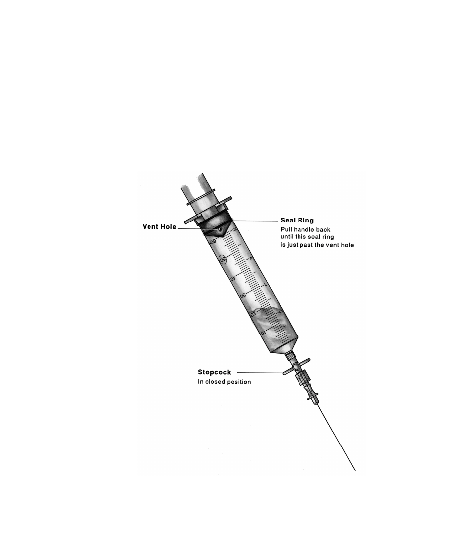
Preprogramming and pre-testing the pump 83
OPTIONAL
25. Use this step only if the plunger is not moving forward while filling
the reservoir.
26. With the refill needle pointing down, vent the syringe head space by
pulling back firmly on the plunger until the second sealing ring on the
black rubber cap passes beyond the vent hole (see Figure 7).
Figure 7: Venting the Syringe Head Space
Dmp9196021-011_c.book Page 83 Thursday, April 4, 2002 8:15 AM

Pump Implantation
84
27. With the stopcock closed, press the refill needle into the Pump fill
port.
28. Open the stopcock. Maintain downward pressure on the barrel of the
syringe to ensure the inlet valve of the Pump remains open.
Never push on the refill syringe plunger to
fill the Pump. When the refill needle is
properly seated in the fill port of the
Pump, the vacuum in the reservoir will
draw the insulin from the syringe.
29. Allow the Pump vacuum to draw the INSULIN into the reservoir.
When the INSULIN stops moving, the Pump is filled. Close the stop-
cock and remove the syringe.
30. Prepare the IN1 syringe for aspiration. Remove any air from the
syringe, prime the needle, close the stopcock and obtain a vacuum by
pulling back on the plunger until it locks. Press the lock into the
plunger groove to be sure it is firmly secured. A fluid barrier of at
least 2 mL should remain in the syringe.
31. Press the refill needle back into the Pump fill port with the stopcock
closed.
32. Open the stopcock and empty the Pump. Allow 30 seconds after the
INSULIN level appears to have stopped rising in the refill syringe to
assure the Pump is completely emptied.
33. Close the stopcock and remove the syringe.
!
WARNING
Dmp9196021-011_c.book Page 84 Thursday, April 4, 2002 8:15 AM