Mertik Maxitrol and KG B6RHAS Control Unit For GV60/Symax System User Manual Users manual Part 2 of 3
Mertik Maxitrol GmbH & Co. KG Control Unit For GV60/Symax System Users manual Part 2 of 3
Contents
- 1. Users manual Part 1 of 3
- 2. Users manual Part 2 of 3
- 3. Users manual Part 3 of 3
Users manual Part 2 of 3
15 / 29
ENGLISH
INSTALLATION AND OPERATING INSTRUCTIONS FOR OEM USE ONLY
© 2018 Mertik Maxitrol GmbH & Co. KG, All Rights Reserved.
DRAFT 21/11/2018
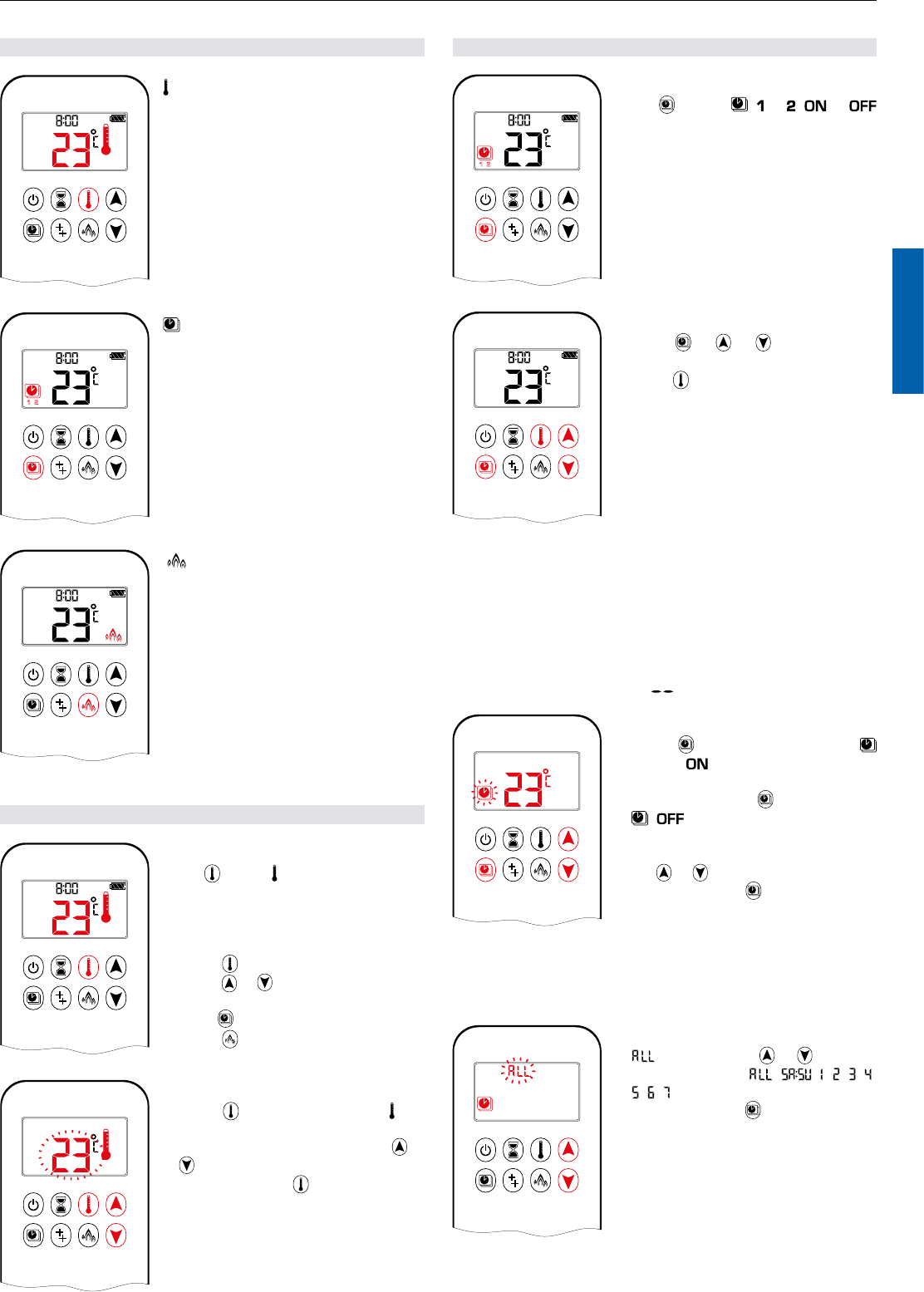
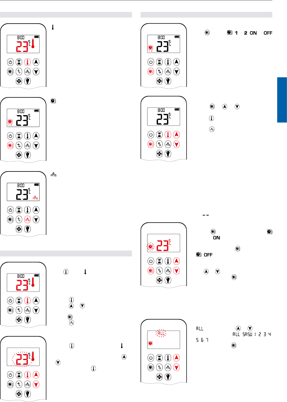
MODES OF OPERATION
1 2
ON
AM
PM
OFF
Thermostatic Mode
The room temperature is measured and
compared to the set temperature. The
ame height is then automatically ad-
justed to achieve the set temperature.
1 2
ON
AM
PM
OFF
Program Mode
PROGRAMS 1 and 2, each can be pro-
grammed to go ON and OFF at specic
times at a set temperature.
AM
Eco Mode
Flame height modulates between high
and low. If the room temperature is low-
er than the set temperature, the ame
height stays on high for a longer period
of time. If the room temperature is high-
er than the set temperature, the ame
height stays on low for a longer period
of time. One cycle lasts approx. 20 min.
THERMOSTATIC MODE
1 2
ON
AM
PM
OFF
ON:
Press button. displayed, preset tem-
perature displayed briey, and then room
temperature displayed.
OFF:
1. Press button.
2. Press or button to enter Manual
Mode.
3. Press button to enter Program Mode.
4. Press button to enter Eco Mode.
1 2
ON
AM
PM
OFF
SETTING:
1. Press button and hold until dis-
played, temperature ashes.
2. To adjust set temperature press or
button.
3. To conrm press button or wait.
PROGRAM MODE
1 2
ON
AM
PM
OFF
ON:
Press button. , or
, or
displayed.
1 2
ON
AM
PM
OFF
OFF:
1. Press or or button to enter
Manual Mode.
2. Press button to enter Thermostatic
Mode.
NOTE: The set temperature for Thermostatic Mode is the tem-
perature for the ON time in Program Mode. Changing
the Thermostatic Mode set temperature also changes
the ON time temperature in Program Mode.
Default settings:
ON TIME (Thermostatic) TEMPERATURE: 70 °F / 21 °C
OFF TIME TEMPERATURE: “ ” (pilot ame only)
1 2
ON
AM
PM
OFF
TEMPERATURE SETTING:
1. Press button and hold until
ashes.
and set temperature (set-
ting in Thermostatic Mode) displayed.
2. To continue press button or wait.
, displayed, temperature ash-
es.
3. Select OFF temperature by pressing
the or button.
4. To conrm press button.
NOTE: The ON (Thermostatic) and OFF set temperatures are
the same for each day.
1 2
ON
AM
PM
OFF
DAY SETTING:
5. ashes. Press or button to
choose between , , , , , ,
, , .
6. To conrm press button.
16 / 29
INSTALLATION AND OPERATING INSTRUCTIONS FOR OEM USE ONLY
© 2018 Mertik Maxitrol GmbH & Co. KG, All Rights Reserved.
DRAFT 21/11/2018
selected
1 2
ON
AM
PM
OFF
ON TIME SETTING (PROGRAM 1):
7. , , displayed, is displayed
shortly, and hour ashes.
8. To select hour press or button.
9. To conrm press button. , ,
displayed, displayed shortly,
and minutes ash.
10. To select minutes press or but-
ton.
11. To conrm press button.
OFF TIME SETTING (PROGRAM 1):
1 2
ON
AM
PM
OFF
12. , ,
displayed, is displayed
shortly, and hour ashes.
13. To select hour, press or button.
14. To conrm press button. , ,
displayed, displayed short-
ly, and minutes ash.
15. To select minutes press or but-
ton.
16. To conrm press button.
NOTE: Either continue to PROGRAM 2 and set on and off times
or stop programming at this point, and PROGRAM 2 re-
mains deactivated.
NOTE: PROGRAM 1 and 2 use the same ON (Thermostatic) and
OFF temperatures for , and Daily Timer ( , , ,
, , , ). Once a new ON (Thermostatic) and / or OFF
temperature has been set, that temperature becomes the
new default setting.
NOTE: If , or Daily Timer are programmed for PRO-
GRAM 1 and PROGRAM 2 ON and OFF times, these
become the new default times. The batteries must be re-
moved to clear the PROGRAM 1 and PROGRAM 2 ON
and OFF times and temperatures.
or Daily Timer ( , , , , , , ) selected
▪ Set ON time and OFF time using same procedure as “ se-
lected” (above).
▪
:
Set ON time and OFF time for both Saturday and Sunday.
▪ Daily Timer: Unique ON and OFF times may be set for a single
day of the week, for multiple days of the week, or for every day
of the week.
▪ Wait to nish setting.
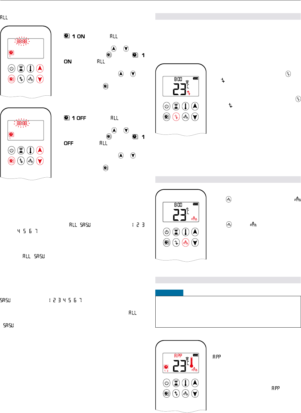
AUXILIARY FEATURE (2ND BURNER FEATURE)
The latching solenoid valve will open automatically after ignition
or after switching the system off, so that the maximum ow of
gas is supplied to both burners assisting with the ignition pro-
cess. After pressing the AUX-button the motor will turn 7 sec-
onds in the ON direction until the max. position is reached.
1 2
ON
AM
PM
OFF
ON:
To switch a burner ON, press the but-
ton. displayed.
OFF:
To switch the burner OFF, press the
button.
disappears.
NOTE: The latching solenoid valve cannot operate manually. If
the receiver battery runs down it will remain in the last
operating position.
ECO MODE
AM
ON:
Press button to enter Eco Mode.
displayed.
OFF:
Press button. disappears.
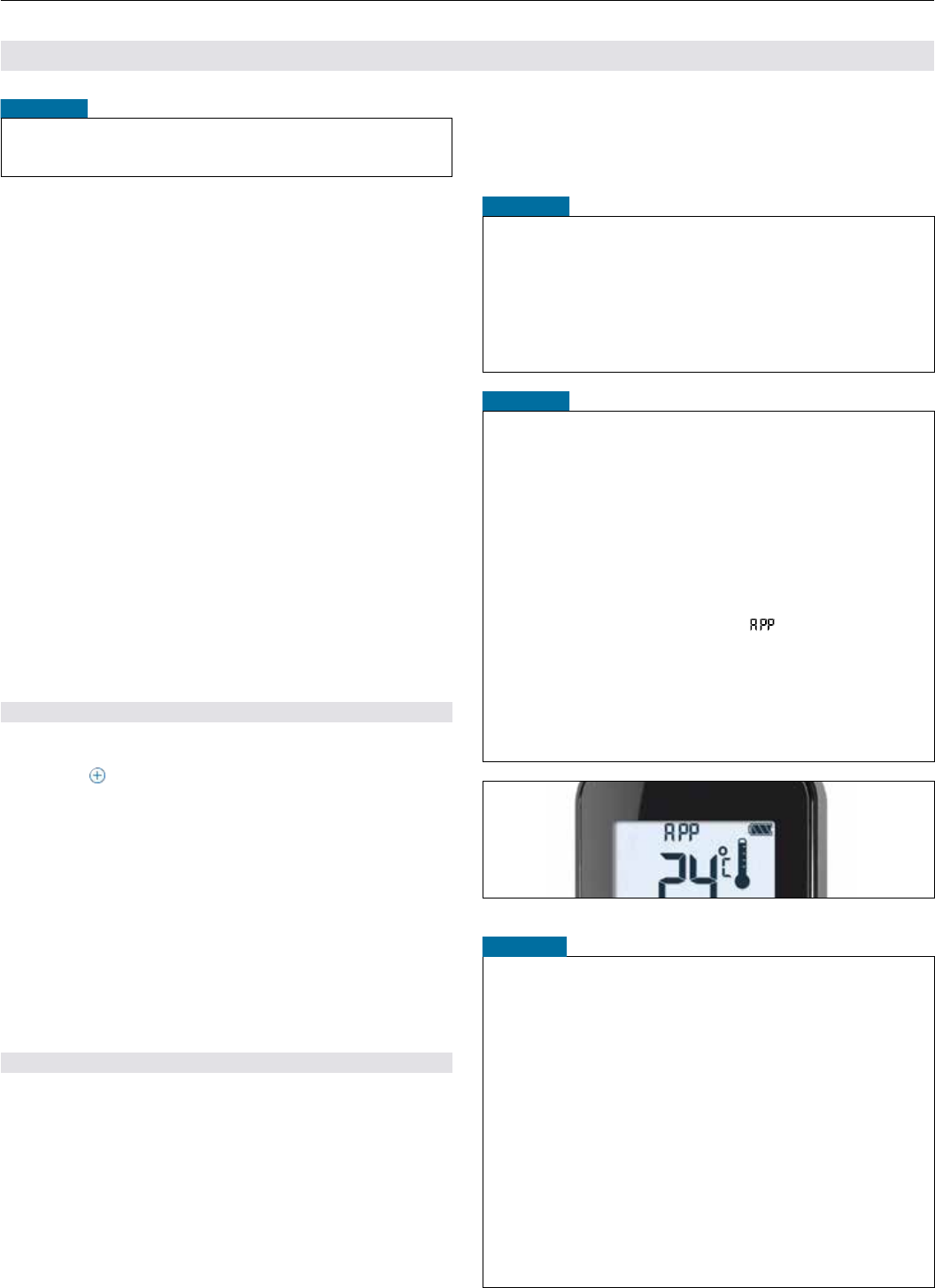
MYFIRE APP
NOTICE
Before the app can be used, the myre Wi-Fi Box must be wired
and plugged into mains power according to myre app setup
diagram (see gure 30, page 29), and the app setup must be
completed (see myre app setup, page 24).
1 2
ON
AM
PM
OFF
If Thermostatic, Program or Eco Mode
is activated, the corresponding icon and
“” is displayed on the handset.
The modes can be operated according
to the descriptions on previous pages.
NOTE: In Manual Mode “” is NOT
displayed on the handset.
17 / 29
ENGLISH
INSTALLATION AND OPERATING INSTRUCTIONS FOR OEM USE ONLY
© 2018 Mertik Maxitrol GmbH & Co. KG, All Rights Reserved.
DRAFT 21/11/2018
CHILD PROOF
1 2
ON
AM
PM
OFF
ON:
To activate press and buttons
simultaneously. displayed and the
handset is rendered inoperable, except
for the OFF function.
OFF:
To deactivate press and buttons
simultaneously. disappears.
SETTING FAHRENHEIT OR CELSIUS
1 2
ON
AM
PM
OFF
To change between °C and °F, press
and buttons simultaneously.
NOTE: Choosing °F results in a 12 hour
clock. Choosing °C results in a
24 hour clock.
SETTING THE TIME
AM
PM
1 2
ON
OFF
1. Press and buttons simultane-
ously. Day ashes.
2. Press or button to select a num-
ber to correspond with the day of the
week (e. g. = Monday, = Tuesday,
= Wed nesday, = Thursday, = F r i -
day, = Sat urday, = Sunday).
3. Press and buttons simultane-
ously. Hour ashes.
4. To select hour press or button.
5. Press and buttons simultane-
ously. Minutes ash.
6. To select minutes press or but-
ton.
7. To conrm press and buttons
simultaneously or wait.
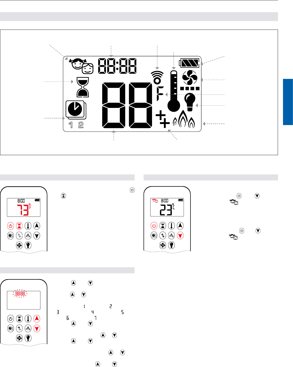
10-SYMBOL OPERATION
Figure 22: 10-symbol Display
Light
Fan
Program Mode
Temperature
Time
Auxiliary Feature (2nd Burner Feature)
Countdown Timer
Battery Status
Signal Indicator Child Proof
Eco Mode
Thermostatic Mode
1 2
ON
AM
PM
OFF
Fahrenheit or Celsius
18 / 29
INSTALLATION AND OPERATING INSTRUCTIONS FOR OEM USE ONLY
© 2018 Mertik Maxitrol GmbH & Co. KG, All Rights Reserved.
DRAFT 21/11/2018
MANUAL MODE (HANDSET)
NOTICE
BEFORE OPERATING
1. Make sure MANUAL knob on the GV60 valve is in the ON,
full counterclockwise position.
2. Place the ON / OFF switch (if equipped) in the I (ON) position.
TO TURN ON FIRE
When pilot ignition is conrmed, motor turns automatically to
maximum ame height.
1 2
ON
AM
PM
OFF
▪ Press button (One Button Ignition)
or and button simultaneously
(Two Button Ignition) until two short
beeps and a blinking series of lines
conrms the start sequence has be-
gun; release button(s).
▪ Main gas ows once pilot ignition is
conrmed.
▪ Handset automatically goes into Man-
ual Mode after main burner ignition.
If the pilot does not stay lit after several tries, turn the main valve
knob to OFF and follow the instructions “TURN OFF GAS TO
APPLIANCE” (see page 9).
STANDBY MODE (PILOT FLAME)
Handset
▪
Press and hold
button
to set appliance to pilot ame.
TO TURN OFF FIRE
1 2
ON
AM
PM
OFF
Handset
▪ Press
button to turn off
.
NOTE: A new ignition is possible after
the OFF icon stops ashing.
FLAME HEIGHT ADJUSTMENT
1 2
ON
AM
PM
OFF
Handset
▪ To increase ame height press and
hold button.
▪ To decrease ame height or to set ap-
pliance to pilot ame, press and hold
button.
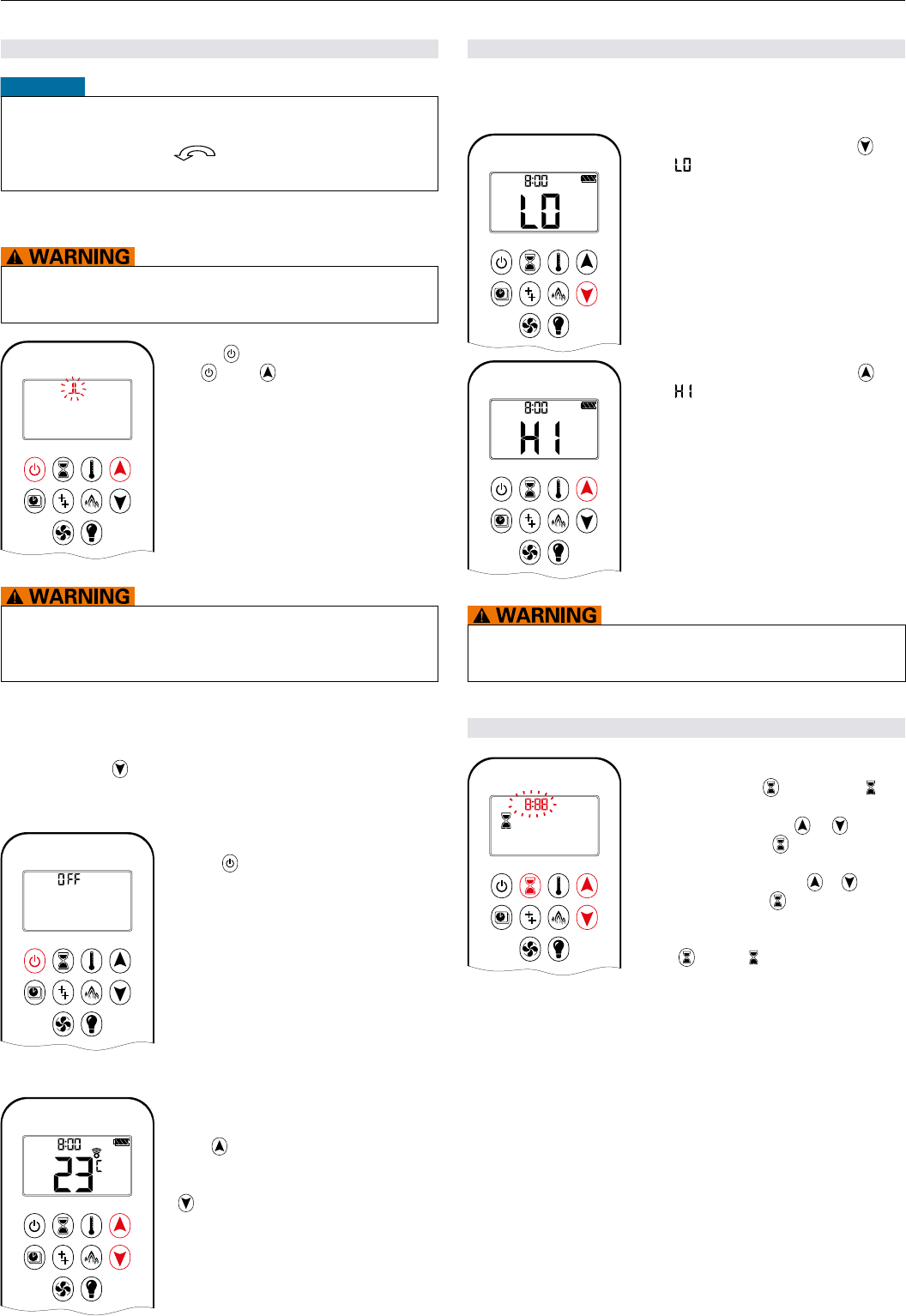
DESIGNATED LOW FIRE AND HIGH FIRE
NOTE: Backlight must be on for high re and low re double-click
operation.
AM
▪ To go to low re, double-click but-
ton. is displayed.
NOTE: Flame goes to high re rst be-
fore going to low re.
AM
▪ To go to high re, double-click but-
ton. is displayed.
If the appliance will not operate, follow the instructions “TURN
OFF GAS TO APPLIANCE”
(see page 9)
.
COUNTDOWN TIMER
1 2
ON
AM
PM
OFF
ON / SETTING:
1. Press and hold button until dis-
played, and hour ashes.
2. To select hour press or button.
3. To conrm press button. Minutes
ash.
4. To select minutes press or button.
5. To conrm press button or wait.
OFF:
Press button,
and Countdown Time
disappear.
NOTE: At end of Countdown Time period, the re shuts off. The
Countdown Timer only works in Manual, Thermostatic,
and Eco Modes. Maximum Countdown Time is 9 hours
and 50 minutes.
19 / 29
ENGLISH
INSTALLATION AND OPERATING INSTRUCTIONS FOR OEM USE ONLY
© 2018 Mertik Maxitrol GmbH & Co. KG, All Rights Reserved.
DRAFT 21/11/2018
MODES OF OPERATION
1 2
ON
AM
PM
OFF
Thermostatic Mode
The room temperature is measured and
compared to the set temperature. The
ame height is then automatically ad-
justed to achieve the set temperature.
1 2
ON
AM
PM
OFF
Program Mode
PROGRAM 1 and 2, each can be pro-
grammed to go ON and OFF at specic
times at a set temperature.
AM
Eco Mode
Flame height modulates between high
and low. If the room temperature is low-
er than the set temperature, the ame
height stays on high for a longer period
of time. If the room temperature is high-
er than the set temperature, the ame
height stays on low for a longer period
of time. One cycle lasts approx. 20 min.
THERMOSTATIC MODE
1 2
ON
AM
PM
OFF
ON:
Press button. displayed, preset tem-
perature displayed briey, and then room
temperature displayed.
OFF:
1. Press button.
2. Press or button to enter Manual
Mode.
3. Press button to enter Program Mode.
4. Press button to enter Eco Mode.
1 2
ON
AM
PM
OFF
SETTING:
1. Press button and hold until dis-
played, temperature ashes.
2. To adjust set temperature press or
button.
3. To conrm press button or wait.
PROGRAM MODE
1 2
ON
AM
PM
OFF
ON:
Press button. , or
, or
displayed.
1 2
ON
AM
PM
OFF
OFF:
1. Press or or button to enter
Manual Mode.
2. Press button to enter Thermostatic
Mode.
3. Press button to enter Eco Mode.
NOTE: The set temperature for Thermostatic Mode is the tem-
perature for the ON time in Program Mode. Changing
the Thermostatic Mode set temperature also changes
the ON time temperature in Program Mode.
Default settings:
ON TIME (Thermostatic) TEMPERATURE: 70 °F / 21 °C
OFF TIME TEMPERATURE: “ ” (pilot ame only)
1 2
ON
AM
PM
OFF
TEMPERATURE SETTING:
1. Press button and hold until
ashes.
and set temperature (set-
ting in Thermostatic Mode) displayed.
2. To continue press button or wait.
, displayed, temperature ash-
es.
3. Select OFF temperature by pressing
the or button.
4. To conrm press button.
NOTE: The ON (Thermostatic) and OFF set temperatures are
the same for each day.
1 2
ON
AM
PM
OFF
DAY SETTING:
5. ashes. Press or button to
choose between , , , , , ,
, , .
6. To conrm press button.
20 / 29
INSTALLATION AND OPERATING INSTRUCTIONS FOR OEM USE ONLY
© 2018 Mertik Maxitrol GmbH & Co. KG, All Rights Reserved.
DRAFT 21/11/2018
SELECTED
1 2
ON
AM
PM
OFF
ON TIME SETTING (PROGRAM 1):
7. , , displayed, is displayed
shortly, and hour ashes.
8. To select hour press or button.
9. To conrm press button. , ,
displayed, displayed shortly,
and minutes ash.
10. To select minutes press or but-
ton.
11. To conrm press button.
OFF TIME SETTING (PROGRAM 1):
1 2
ON
AM
PM
OFF
12. , ,
displayed, is displayed
shortly, and hour ashes.
13. To select hour, press or button.
14. To conrm press button. , ,
displayed, displayed short-
ly, and minutes ash.
15. To select minutes press or but-
ton.
16. To conrm press button.
NOTE: Either continue to PROGRAM 2 and set on and off times
or stop programming at this point, and PROGRAM 2 re-
mains deactivated.
NOTE: PROGRAM 1 and 2 use the same on (Thermostatic) and
off temperatures for , and Daily Timer ( , , , , ,
, ). Once a new on (Thermostatic) and / or off tempera-
ture has been set, that temperature becomes the new
default setting.
NOTE: If , or Daily Timer are programmed for PRO-
GRAM 1 and PROGRAM 2 on and off times, these be-
come the new default times. The batteries must be re-
moved to clear the PROGRAM 1 and PROGRAM 2 on
and off times and temperatures.
or Daily Timer ( , , , , , , ) selected
▪ Set on time and off time using same procedure as “ se-
lected” (above).
▪
:
Set on time and off time for both Saturday and Sunday.
▪ Daily Timer: Unique on and off times may be set for a single
day of the week, for multiple days of the week, or for every day
of the week.
▪ Wait to nish setting.
AUXILIARY FEATURE (2ND BURNER FEATURE)
The latching solenoid valve will open automatically after ignition
or after switching the system off, so that the maximum ow of
gas is supplied to both burners assisting with the ignition pro-
cess. After pressing the AUX-button the motor will turn 7 sec-
onds in the ON direction until the max. position is reached.
1 2
ON
AM
PM
OFF
ON:
To switch a burner on, press the but-
ton. displayed.
OFF:
To switch the burner off, press the
button.
disappears.
NOTE: The latching solenoid valve cannot operate manually. If
the receiver battery runs down it will remain in the last
operating position.
ECO MODE
AM
ON:
Press button to enter Eco Mode.
displayed.
OFF:
Press button. disappears.
CIRCULATING FAN OPERATION
AM
Circulating fan has 4 speed levels from
low (1 bar) to high (4 bars).
SETTING:
1. Press button and hold until
ashes.
2. Press button to increase fan speed
and button to decrease fan speed.
3. To conrm setting either press but-
ton or wait ( displayed).
OFF:
Press button until all 4 speed level
bars disappear.
NOTE: SETTING only. If the fan was not switched off after last
use, it starts automatically 4 minutes after ignition at max-
imum speed and goes to the last set level after 10 sec-
onds. The fan stops 10 minutes after the gas is OFF or
at pilot.
21 / 29
ENGLISH
INSTALLATION AND OPERATING INSTRUCTIONS FOR OEM USE ONLY
© 2018 Mertik Maxitrol GmbH & Co. KG, All Rights Reserved.
DRAFT 21/11/2018
AM
ON:
Press button ( displayed). Light is
on at preset level.
OFF:
Press button ( disappears).
SETTING:
1. Press button and hold until ash-
es.
2. To adjust light between 20…100 %
press or button.
3. To conrm setting either press but-
ton or wait ( displayed).
NOTE: The Light works independently of the pilot ame. If you
want the light on but no ame, press button.
MYFIRE APP
NOTICE
Before the app can be used, the myre Wi-Fi Box must be wired
and plugged into mains power according to myre app setup
diagram (see gure 30, page 29), and the app setup must be
completed (see myre app setup, page 24).
1 2
ON
AM
PM
OFF
If Thermostatic, Program or Eco Mode
is activated, the corresponding icon and
“” is displayed on the handset.
The modes can be operated according
to the descriptions on previous pages.
NOTE: In Manual Mode “” is NOT
displayed on the handset.
LIGHT / DIMMER OPERATION
22 / 29
INSTALLATION AND OPERATING INSTRUCTIONS FOR OEM USE ONLY
© 2018 Mertik Maxitrol GmbH & Co. KG, All Rights Reserved.
DRAFT 21/11/2018
The Puck is a smart control that works in conjunction with the
GV60 / Symax system. Its basic functions include turning the re
on and off and turning the ame height up and down.
The Puck is equipped with temperature sensing that allows the
use of the popular myre app.
ON / OFF
Up / HIDown /LO
Figure 23: 3-button layout
TECHNICAL DATA
AMBIENT TEMPERATURE RANGE
CSA: The Puck: 32 °F to 131 °F
CE: The Puck: 0 °C to 55 °C
RADIO FREQUENCY
CSA: 918 MHz for U.S. and for Canada (The Puck, receiver)
CE: 868 MHz for Europe (The Puck, receiver)
(see radio frequency information on page 4.)
POWER SUPPLY
Handset: 2 x 1.5 V “AAA” (quality alkaline recommended)
NOTICE
Wiring of valve and receiver must be completed before starting
ignition. Failure to do so could damage the electronics.
NOTICE
The handsets and receivers are not interchangeable with
previous electronics.
To avoid damaging the electronics, do NOT use metal tools to
remove the batteries from the handset / receiver.
▪ Without using a mains adapter, battery replacement is recom-
mended at the beginning of each heating season.
▪ Old or dead batteries should be removed immediately. If left
in the unit the batteries can overheat, leak, and / or explode.
▪ Do NOT expose batteries (including during storage) to direct
sunlight, excessive heat, re, moisture, or severe impact. Each
of these conditions can cause the batteries to overheat, leak,
and / or explode.
▪ Batteries must be kept within their recommended temperature
limits (ambient battery temperature range: 32 °F to 131 °F /
0 °C to 55 °C).
▪ New and old batteries and different brands of batteries should
not be used together. Mixing of various batteries can cause
the batteries to overheat, leak, and / or explode.
THE PUCK HANDSET
SYNCHRONIZATION RECEIVER / THE PUCK HANDSET
NOTICE
See page 7 for more information about synchronization between
receiver and The Puck handset.
MODES OF OPERATION
When pilot ignition is conrmed, motor turns automatically to
maximum ame height.
TURN FIRE ON AND OFF
▪ Press and hold the button until two
short beeps conrms the start se-
quence has begun; release button.
▪ Main gas ows once pilot ignition is
conrmed.
▪ Press and hold the
button to turn
OFF
.
If the pilot does not stay lit after several tries, turn the main valve
knob to OFF and follow the instructions “TURN OFF GAS TO
APPLIANCE” (see page 9).
STANDBY MODE (PILOT FLAME)
▪ Press and hold the "–" button to set
appliance to pilot ame
FLAME HEIGHT ADJUSTMENT
▪ To increase ame height press and
hold "+" button.
▪ To decrease ame height or to set ap-
pliance to pilot ame, press and hold
"–" button.
DESIGNATED LOW FIRE AND HIGH FIRE
▪ To go to hi re, double-click "+" button.
▪
To go to low re, double-click "–" button.
NOTE: Flame goes to high re rst be-
fore going to low re.
If the appliance will not operate, follow the instructions “TURN
OFF GAS TO APPLIANCE”
(see page 9)
.
23 / 29
ENGLISH
INSTALLATION AND OPERATING INSTRUCTIONS FOR OEM USE ONLY
© 2018 Mertik Maxitrol GmbH & Co. KG, All Rights Reserved.
DRAFT 21/11/2018
MYFIRE WI-FI BOX (B6R-W2…)
The new Wi-Fi Box has a faster processing speed, variable power
supply between 5 and 24 volts, two RGB outlets, identical con-
nectors on both ends of the cable, and the Wi-Fi Box itself has a
much smaller footprint.
TECHNICAL DATA
AMBIENT TEMPERATURE RANGE
CSA: myre Wi-Fi Box: 32 °F to 176 °F
CE: myre Wi-Fi Box: 0 °C to 80 °C
RADIO FREQUENCY
CSA + CE: 2.4 GHz
(see radio frequency information on page 4.)
POWER SUPPLY
6 V connection to the receiver which is connected to an AC
mains adapter.
WIRELESS COMMUNICATION
▪ WPA2 authentication
▪ AES 256-bit encryption security
▪ Compatible with IEEE 802.11 b/g/n
POWER CONSUMPTION
CSA + CE: Nominal: max. 0.5 W
CSA + CE: Standby: max. 5 mA
LED RGB CONTROL OUTPUT
CSA + CE: Phoenix, 3 pol, MC 1.5 / 3-ST-3.5,
5 VDC - 24 VDC / 5 A
LED RGB EXTERNAL POWER INPUT
CSA + CE: Phoenix, 2 pol, MC 1.5 / 2-ST-3,
5 VDC - 24 VDC / 5 A
MODES OF OPERATION
The myre Wi-Fi Box communicates with a home network (Wi-Fi
Router) over a wireless signal.
1. The myre Wi-Fi Box must be wired to the receiver according
to the myre app setup diagram (see gure 30, page 29)
2. Connect receiver to mains power. The myre Wi-Fi Box start
with the Access Point Mode (green/blue LED blinking). Go to
“myre app setup”…
MINIMUM REQUIREMENT FOR WI-FI ROUTER
▪ IEEE 802.11n/g/b compatibility
▪ WPA2 encryption
▪ Radio frequency: 2.4 GHz band
▪ Wireless auto channel: Automated search for WLAN radio
channel free of interference
▪ User Datagram Protocol (UDP) support
▪ multicast DNS (mDNS) for Kwik Connect process
MINIMUM REQUIREMENT SMART DEVICE:
▪ iOS 8.0 or Android 4.2
Reset button
(Use paper clip to push button)
Receiver
LED 1
RGB
Power Input Receiver cable
RGB 1 RGB 2
Figure 24: myre Wi-Fi Box (B6R-W2…)
LED INDICATION ON MYFIRE WI-FI BOX (see gure 24, page 23)
2 RGB LEDs
Label LED Status
Receiver
LED 1
Green Connected to receiver.
Red Not connected to receiver.
Off Standby mode is active or no Power supply.
WLAN
LED 2
Green Wi-Fi connection is safe.
Blue/Green blinking Access point mode (AP mode) is active.
Red Not connected to home network (Wi-Fi Router).
Off Standby mode is active or no power supply.
RESET STATUS ON MYFIRE WI-FI BOX:
Press Reset
Button
LED Function
Power-On-
Reset or
1-sec-Reset
WLAN LED 2
ashes red,
green and
blue
If no network is set, the AP Mode will be activated
for 2 hours. When the network isn't set after 2
hours, the Wi-Fi Box will go to Standby Mode.
Once a network is set, the Wi-Fi Box will connect
directly.
7 secs WLAN LED 1
ashes every
500 ms in blue
Removes the Wi-Fi settings and turns on the
Access point mode (AP mode) for 2 hours.
20 secs WLAN LED 1
ashes every
50 ms in blue
Erases all Setup Data. The Wi-Fi chip will be set
to the last version after the reboot. The AP-Mode
will be activated for 2 hours.
NOTICE
▪ A Symax handset or The Puck must be used to achieve full
functionality.
▪ If mains power is lost, disconnect the myre Wi-Fi Box from
the receiver. This will prevent receiver batteries from being
drained quickly.
▪
Multiple users on the same Wi-Fi channel may interfere with the
data transfer. Press reset button on the myre Wi-Fi Box for 1
second to change current channel (see gure 24, page 23).
▪ If no network is congured, the myre Wi-Fi Box will leave the
Access Point Mode (AP Mode) after 2 hours.
▪ If you have multiple replaces using myre Wi-Fi Boxes, the
minimum distance between the myre Wi-Fi Boxes must be 60
cm (2'). A shorter distance may interfere with the data transfer.
Do not connect the combination control system to the LED
connections of the myre Wi-Fi Box.
WLAN
LED 2
24 / 29
INSTALLATION AND OPERATING INSTRUCTIONS FOR OEM USE ONLY
© 2018 Mertik Maxitrol GmbH & Co. KG, All Rights Reserved.
DRAFT 21/11/2018
MYFIRE APP SETUP
NOTICE
For myre app setup, you will need your Wi-Fi network SSID
and password.
For more detailed app setup / operating instructions refer to
www.myreapp.com
INITIAL SETUP
1. Download myre app from Apple App Store or Google Play
Store.
2. Touch screen to start app setup.
3. Choose language, temperature (°C or °F) and time format
(12 or 24 hour).
REGISTRATION
NOTE: You must register before logging in. Registration is one
time only.
1. Fill in data and accept the “Privacy Policy”.
2. Touch “OK” in pop-up notice.
3. Touch link to conrm email verication.
4. You will be shown a message that you have successfully reg-
istered the myre app.
5. Return to app.
LOGIN
1. Fill in your registration password.
2. Accept “Terms and Conditions”.
3. Touch the “Login” button.
KWIK CONNECT
CONNECT SMART DEVICE TO MYFIRE WI-FI BOX
1. Touch the icon.
2. The Home Wi-Fi Network name your smart device is currently
connected to is displayed.
3. Type in the password of the displayed Home Wi-Fi Network.
4. Touch "Connect". The myre App starts connecting the myre
Wi-Fi Box to the selected Home Wi-Fi Network.
COMPLETE MYFIRE APP SETUP
1. Type in a name for your replace or select an icon.
2. Activate Fan, Light and AUX if installed to your replace.
3. Touch "Finish" to complete the setup.
The home screen is displayed and the myre app is ready to go.
STANDARD SETUP
IF KWIK CONNECT IS NOT AVAILABLE, AND YOU HAVE EN-
TERED THE CORRECT PASSWORD, USE STANDARD SETUP.
1. Type in the password of the displayed Home Wi-Fi Network.
2. Follow the instructions on the screen and touch the "Standard
Setup" button to proceed.
3. Go to your smart device Wi-Fi settings and select the myre
Wi-Fi Box network (myre_WiFi-Box_<number>) you want to
connect.
4. Go back to the myre app setup and follow the instructions on
the screen. Your selected Wi-Fi Box network name from the
smart device Wi-Fi settings.
USE RETRY IF PASSWORD IS INCORRECT
1. Touch the "Retry" button to repeat the Kwik Connect process.
2. Type in the correct password.
NOTICE
To connect myre Wi-Fi Box to Wi-Fi Router (home network),
make sure:
▪ Home network is available.
▪ Home network name and password are correct.
▪ SSID of the Wi-Fi Router is not hidden.
▪ Home network signal is in range.
▪ Wi-Fi Router supports User Datagram Protocol (UDP).
NOTICE
▪ After setting up the myre Wi-Fi Box and myre app, the time
has to be synchronized in the settings of the myre app.
▪ The active device (The Puck or Symax handset or smart
device) is the one last used. An exception is if the non-active
devise is used to change Light, Fan, or AUX. The non-active
device will make the changes, but the active device remains
so if it is in Thermostatic, Program, or Eco Mode. If a Prole
includes a Thermostatic, Program, or Eco setting it will also
cause the active device to remain active.
▪ If Thermostatic, Program, or Eco Mode is activated using the
app, the corresponding icon and “ ” is displayed on the
Symax handset (see gure 25, page 24).
▪ During motor movement no information between receiver and
transmitter is exchanged. The synchronization follows after
motor has stopped.
▪ The room temperature data is transferred by the handset
during synchronization.
Figure 25: App connected (in Thermostatic Mode)
It is the responsibility of the OEM to consider the following:
▪ The location of the GV60 system components will signicantly
effect the radio signal strength.
▪
The type of materials (e.g. sheet metal) used in the construction of
the gas replace will signicantly effect the radio signal strength.
▪ Operate the system with a dedicated mains power supply
and/or batteries.
▪ Do not use near household electrical wiring and/or magnetic
elds.
▪ Other transmitters using the same signal will negatively affect
the radio signal strength.
▪ Adjustment of the on-board antenna on the receiver can
improve signal strength.
▪ Do not store or locate the GV60 system components in a hot,
cold, or humid environment.
NOTICE
25 / 29
ENGLISH
INSTALLATION AND OPERATING INSTRUCTIONS FOR OEM USE ONLY
© 2018 Mertik Maxitrol GmbH & Co. KG, All Rights Reserved.
DRAFT 21/11/2018
ON-OFF
UP
DOWN
Figure 26
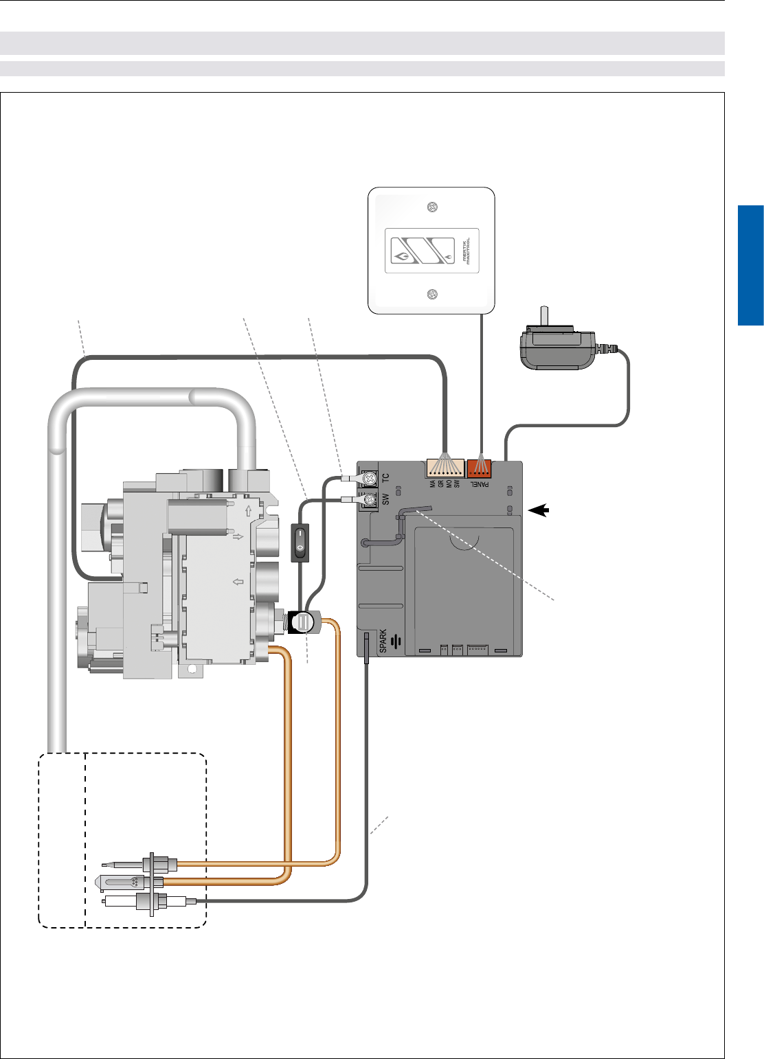
BASIC
Pilot Burner
G30-ZP2M-L
Wall Switch (optional)
G6R-ZWSE(N)…
Receiver
B6R-R8(9)P…
Thermocurrent Cable SW
with ON / OFF Switch
G60-ZSKS(L)S…
Thermocurrent Cable TC
G60-ZKIRS…
8 Wire Cable
G6R-C…
Interrupter Block
G60-ZUS…
Mains Adapter (optional)
G60-ZMA3
Ignition Cable
G60-ZKIS…
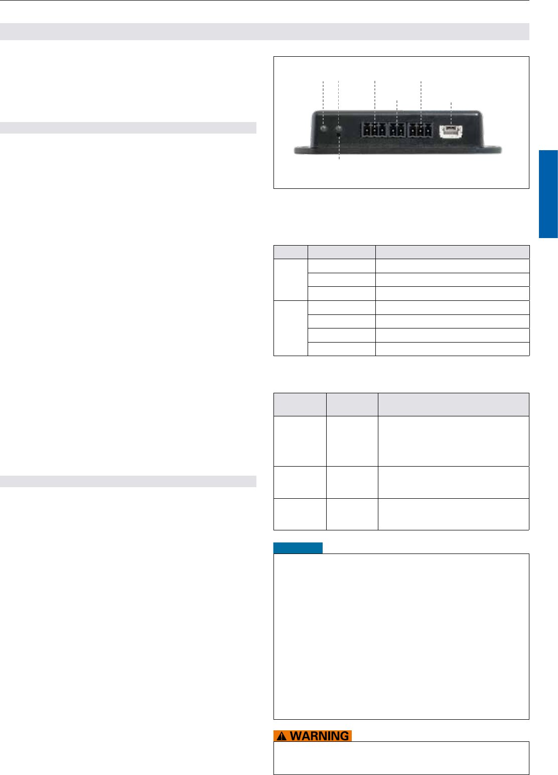
RESET Button
Additional functions
The universal receivers B6R-R8(9)P… and B6R-R8(9)PT… can be used to start a power ue con-
trol (2pin outlet) or to operate a second burner or a relay (3pin outlet). Together with a module, the
receiver controls a circulating fan and a dimmer.
The receiver B6R-R8(9)PT… has main burner supervision (2nd thermocouple option). This option is
programmed so that it cannot be used without the second thermocouple installed and vice versa.
Main Burner
Combination Control
GV60…
Antenna
WIRING DIAGRAMS