Motorola Solutions 92FT7089 Mobile 2-Way Portable Radio with Bluetooth, Bluetooth LE and WiFi User Manual Installation Manual 3 of 4
Motorola Solutions, Inc. Mobile 2-Way Portable Radio with Bluetooth, Bluetooth LE and WiFi Installation Manual 3 of 4
Contents
Installation Manual 3 of 4

MN003109A01_aa
Standard Configurations Planning the Installation 2-13
2.1.3.2 Remote Mount: Power, Ignition, and Emergency Cable Installation
The single control head O2, O5, O7 or O9 remote mount configurations receive power from the J200
connector’s red and black wires. The yellow wire at J200 is one ignition sense wire. On mid power
radios, the J2 connector can also be used for ignition sense. If the HLN6863 is attached at J100 of
the O2, O5, O7 or O9 control head, the “thin red” wire will NOT function as an ignition sense wire,
since the J100 connector has no ignition sense electrical connection.
NOTE: It is incorrect for installation to attach ignition sense at more than one wire or connector.
Refer to Table 2-1 or Table 2-2 for its correct wiring configurations.
The O3 control head receives its power down the CAN cable, and detects the ignition state by the
ignition sense pin at J2. On mid power radios, the J2 connector can also be used for ignition sense.
In Multi-Control Head installations, the yellow ignition wire must be connected to the head assigned
ID # 1. Section 2.2.2.4: “Setting the Initial Control Head ID” for further information.
The design of the control head is different compared to the transceiver, therefore it is also NOT
necessary to attach HLN6863 at J100 to prevent accidental emergency operation. The control head
can have an emergency accessory attached at connector J100 instead of at the transceiver
connector J2. Wherever the emergency accessory is placed, it is recommended to only attach at one
location rather than multiple emergency accessories attached at different points of the radio.
Draft
ergenergen
emergencyemergency
MN003109A01_aa
2-14 Standard Configurations Planning the Installation
Table 2-1. Dash and Remote O2, O3, O5, O7 or O9 Radio Power ON @ J2
Dash/Remote
Mount
Transceiver
Red Power
Wire
HLN6863
Thin Red Wire
@ J2
Transceiver
Red Power
Wire
HLN6863
Thin Red Wire
@ J2
Transceiver
Red Power
Wire
HLN6863
Thin Red Wire
@ J2
Connected to
battery
XXX X
Connected to
ignition switch
XXX
Ignition switch
controls
No ignition switch control. Enables ignition switch functionality
as programmed in the codeplug.
Illegal wiring configuration. See
CAUTION note.
Table 2-2. Remote O2, O5, O7 or O9 Radio Power ON @ J200
Remote
Control Head
Red Wire
@J200
Control Head
Yellow Wire
@J200
Control Head
Red Wire
@J200
Control Head
Yellow Wire
@J200
Control Head
Red Wire
@J200
Control Head
Yellow Wire
@J200
Connected to
battery
XXX X
Connected to
ignition switch
XXX
Ignition switch
controls
No ignition switch control. Enables ignition switch functionality
as programmed in the codeplug.
Illegal wiring configuration. See
CAUTION note.
Table 2-3. Ignition Interface Cables
Part Number Description
HLN6863_ Cable, M.A.P. 26pin with Only Ignition and SPK
KT000274A01 Y-Cable, M.A.P to M.A.P. and DB 25
DO NOT connect any wires to the battery terminals until you have finished the entire
radio installation (Dash or Remote Mount) configuration to avoid potential equipment
damage.
Incorrect wiring of the radio may result in incorrect ignition sense detection, incorrect
power-on state, or incorrect power-off state of the radio system.
The Control Head Power cable wire (RED) and Transceiver Power cable wire (RED)
are always attached to the battery terminal and NOT to the ignition switch.
!
C a u t i o n
ft
and DB 25d DB
aft
with Only Ignition andh Only Ignition an
aft
DescriptionDescription
Draf
EnablesEnables
ignition switc ignit
as programmed in the cas programm
Ignition Interface Cablestion Interface Cables
Dr
D
D
D
Dr
ra
af
aft
aft
ft
t

MN003109A01_aa
Standard Configurations Planning the Installation 2-15
2.1.4 Ignition Sense Switch (Radio Wide Advance)
CPS selectable settings to control the radio’s functionality based on the state of the vehicle’s Ignition
status. These descriptions can be found in the CPS (customer programming software) tool HELP
Guides and are repeated here for convenience.
Table 2-4. Ignition Sense Switch Settings in CPS
Feature Description
Blank • Radio POWERS ON when the Power Button is pressed or with the emergency power up
feature.
• Radio POWERS OFF when the Power Button is pressed.
TX Inhibit (Available only when: the radio is model/option capable)
• Radio POWERS ON with a radio Power On button / knob selection.
• Radio POWERS OFF with a radio Power Off button / knob selection, or when the Inactiv-
ity Auto Power Off timer expires.
•While “IGNITION” is not present, certain communications are not possible:
I. The radio does not register with ASTRO 25 (APCO) - Trunking Systems and there-
fore cannot receive this type of Trunking communications (see the System Type
field), however, Type II Trunking Systems can receive dispatch without being regis-
tered.
II. Also, the radio cannot be powered-on with the Emergency Power UP feature, and
Emergency Alarm transmissions using the Emergency Power UP footswitch are not
possible.
PTT TX Inhibit (Available only when: the radio is model/option capable)
• Radio POWERS ON with a radio Power On button / knob selection.
• Radio POWERS OFF with a radio Power Off button / knob selection, or when the Inactiv-
ity Auto Power Off timer expires.
•While “IGNITION” is not present, all PTT button transmissions are inhibited:
I. The radio does not register with ASTRO 25 (APCO) - Trunking Systems and
therefore cannot receive this type of Trunking communications (see the System
Type field), however, Type II Trunking Systems can receive dispatch without
being registered.
II. Also, the radio cannot be powered-on with the an Emergency Power UP
footswitch-press; however, the footswitch can be used to initiate Emergency
Alarm transmissions if the radio is already on.
Required • Radio POWERS ON when the Power Button is pressed and Ignition is present.
• Radio POWERS ON when Ignition is cycled and radio was previously ON.
• Radio POWERS OFF when the Power Button is pressed, or when Ignition is lost.
Soft Power Off • Radio POWERS ON when the Power Button is pressed, or when Ignition is detected.
• Radio POWERS OFF when the Power Button is pressed, or when Ignition is lost.
Ignition Only Power Up • Radio POWERS ON when Ignition is present.
• Radio POWERS OFF when Ignition is lost.
• Control head power button is ignored.
raft
n: the radio is model/option ca: the radio is model/o
N with a radio Power On buttith a radio Power On butt
with a radio Power Off button with a radio Power Off butto
xpires.xpires.
ent, all ent, all
PTT button tra
PTT button t
ft
Dra
ONON
” i
adio does adio does
nn
D
e e
cannotcan
D
receive ceiv
field), however, Type II field), however, Typ
tered.tere
lso, the radio so, the radio
cannot cannot
Dr
be pow
ergency Alarm transmissions rgency Alarm transm
e.
ter with ASTROter with AST
is type of Ttype
runk
runk
ra

MN003109A01_aa
2-16 Standard Configurations Planning the Installation
NOTE: When either TX Inhibit, PTT TX Inhibit or Required are selected, the Emergency Power Up
feature will not be available to the radio-user.
When any other Ignition Switch setting is made, Emergency Power Up is available to the
radio-user, regardless of current ignition state.
Any optional inactivity time-out timer setting in CPS may delay the power off of the radio once
Ignition sense is removed.
Draft
MN003109A01_aa
Standard Configurations Planning the Installation 2-17
2.1.5 Motorola Branded SB9600 Siren/PA Configuration/Programming
The Siren/PA is shipped pre-wired for 100W operation. It can be rewired for 65W, 75W, or 130W
power levels.
To change to another power level, perform the following:
1. Open the Siren/PA connector cover to gain access to the two-connector speaker leads. Do
not change the speaker common lead (pin 20). The other lead is connected to pin 35 (for
100W operation).
2. Using an appropriate pin removal tool, extract pin 35 and move it to one of the following pin
locations:
- pin location 36 for 75W operation
- pin location 28 for 65W or 130W operation
3. For 65W or 75W operation, no further changes are required. Reassemble the connector.
4. For 130W operation, you must parallel two 11ȍ speakers, each rated at 65W minimum.
Proper phasing of the two speakers is important--when connecting two speakers in parallel,
wire similar speaker terminals together to ensure maximum loudness and prevent
"deadspots." For example, if the terminals are marked "1" and "2", connect the terminals
marked "1" together and connect those wires to one speaker lead. Connect the terminals
marked "2" together and connect those wires to the other speaker lead.
5. When the Siren/PA is configured for dual speaker, 130W operation, it is necessary to remove
a resistor and move two jumpers to set the correct power level. Remove the Siren/PA cover,
and locate resistor R219 (0 ohm). This resistor should be removed for 130W operation.
Locate jumpers JU100 and JU101. These jumpers should be installed for 130W operation.
6. Close and reconnect the Siren/PA connector cover.
NOTE: Jumpers JU100 and JU101 do not affect the Siren output level. JU100 and JU101
compensate for the lower speaker load and the two speakers in parallel, by
decreasing the gain U102-1. JU100 affects the radio PA level and JU101 affects the
PA audio level.
Pin locations of various power level configurations are listed in Table 2-5
Before continuing, remember that under a high-line supply condition
(16.6V), up to 30% more power will go to the speaker(s) after
reconfiguring for 130W operation. Do this only when your PA
speakers are capable of handling the extra power.
Table 2-5. Power Level Configurations
Pin location of speaker
leads R219 JU100/JU101
65W 20,28 IN Across pins A and B
75W 20,36 IN Across pins A and B
100W 20,35 IN Across pins A and B
130W 20,28 OUT Across pins B and C
!
C a u t i o n
aft
r dual speakdual speak
er, 130W ope
er, 130W op
t the corrt the corr
ect power le
power
esisi
stor should bestor should be
umpers shopers
ove
ve
Draf
ontinuing, remember that untinuing, remember
to 30% %
more power will gomore pow
Dr
na
na
ple, if thple, if th
and connect and connect
er and connect ter and connect
ho
or 130W operation. Do this130W operation. D
able of handling the extra pof handling the extra
Dr
af
MN003109A01_aa
2-18 Standard Configurations Radio Mounting
2.2 Radio Mounting
The mounting location must be accessible and visible. Select a location that will permit routing the
RF antenna cable as directly as possible.
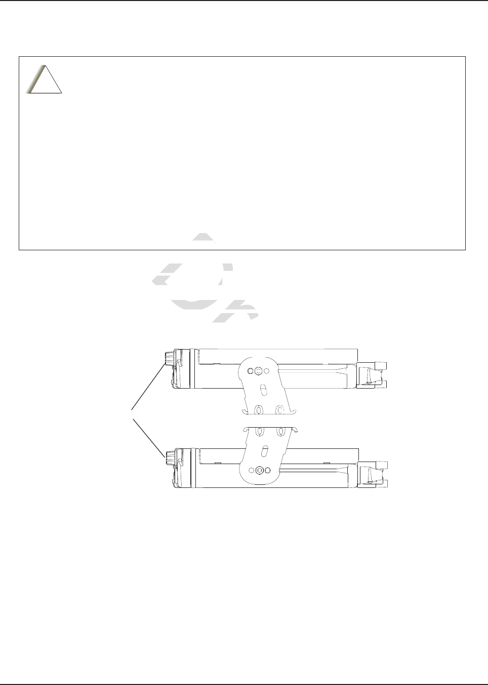
NOTE: For optimum radio performance, orient the mounting trunnion as shown in Figure 2-18 for mid
power. For new or existing installations of all use only the APX mobile trunnion, kit number
HLN7002_.
Figure 2-18. APX8500 Mid Power Trunnion Orientation
DO NOT mount the radio on a plastic mounting surface without first reinforcing the
mounting surface; the weight of the radio may crack or break the mounting surface.
DO NOT mount the radio on any surface where the radio could be partially submersed
in water. This is especially important if the cab area of the vehicle is cleaned by
spraying with water. If the radio sits in water for a length of time, moisture may seep
inside the radio and damage the electronic components.
DO NOT allow water to stand in recessed areas of vertically mounted radios. Remove
any moisture immediately to prevent it from seeping down into the radio.
Care must be taken to shield the control head (front and back) from direct exposure to
pressurized water. The pressurized water from a hose, in most cases, is more severe
than the stated test and conditions in typical environments.
!
C a u t i o n
RADIO
APPLIES TO RADIOS IN DASH AND REMOTE INSTALLATIONS
Draf
st be acst be a
cessible ande a
ectly as possible.
ctly as possible.
rformance, orient the mounrformance, orient th
ng inst
allations of all use oallations of
onditondit
io
D
raft
a
a
a
a
a
af
t
ft
f
f
a
af
a
a
a
a
aft
af
aft
af
a
a
a
a
aft
ft
t
aft
aft
t
t
t
a
aft
ft
aft
a
ft
af
ft
ft
raf
t
t
t
ft
f
f
aft
af
aft
a
a
a
a
af
a
a
a
a
af
af
af
af
af
af
af
af
af
af
ft
ft
ft
ft
ft
ft
f
ft
f
f
f
f
t
ft
aft
ft
ft
ft
ft
MN003109A01_aa
Standard Configurations Radio Mounting 2-19
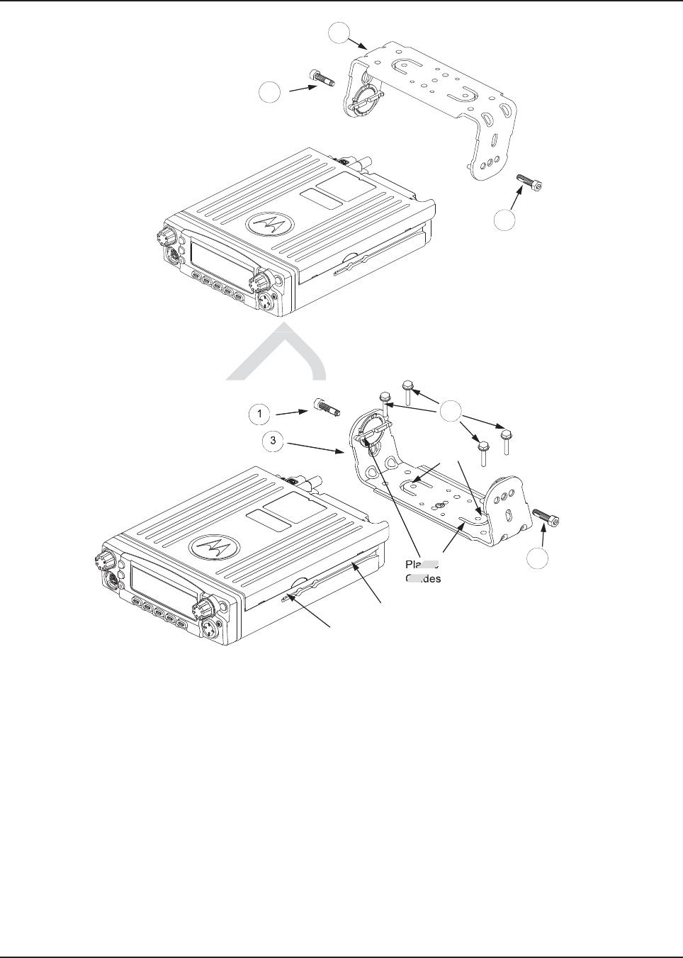
2.2.1 Dash Mount with Trunnion
1. Select the location to mount your radio on the transmission hump (see Figure 2-19) or under
the dash (see Figure 2-20)
NOTE: When mounting the trunnion on the transmission hump take care that the transmission
housing is not affected. Plan your installation ensuring enough room for the Accessory
connector and cable in the back of the radio.
2. Using the trunnion mounting bracket as a template, mark the positions of the holes on the
mounting surface. Use the innermost four holes for a curved mounting surface such as the
transmission hump, and the four outmost holes for a flat surface such as under the dash.
3. Center punch the spots you have marked and realign the trunnion in position.
4. Secure the trunnion mounting bracket with the four self-drilling screws provided
(see Figure 2-19 and Figure 2-20).
5. Ensure that the plastic guides are aligned (horizontal) to the grooves of the trunnion. Slide the
radio into the grooves until it snaps into place (see Figure 2-20).
Table 2-6. Mid Power Trunnion Kit
Item Part Number Description Mid Power Transceiver
1 0371859H01 Trunnion Mounting Screw APX 8500
2 0312002B14 Self-Drilling Tapping Screw APX 8500
3 HLN7002_ Mackinaw Trunnion Hardware Kit APX 8500
raft
on Hardware Kit APX 85on Hardware Kit
af
Dra
Tapping Screw APg Screw
a
Dr
on Mounting Screwon Mounting Screw
D
Descriptionn
D
Table 2-6. MTable 2-6.
D
D
D
Dr
ra
raf
MN003109A01_aa
2-20 Standard Configurations Radio Mounting
Figure 2-19. Transmission Hump Trunnion Mounting
Figure 2-20. Below Dash Trunnion Mounting
6. Secure the radio with two screws provided (Item 1 in Table 2-6). The torque down force for
0371859H01 should be between 50in-lbf to 52in-lbf.
NOTE: This configuration shows the O5 control head. The TIB is used for O3 control head for the
same configuration.
Tabs
Threaded Hole
for Screw
Groove
Plastic
Guides
1
3
2
1
1
1
3
TransmisTransmi
Draft
Dra
aft
aft
aft
aft
Draf
Draf
a
ra
r
Dr
Dr
D
r
ra
r
r
r
r
r
r
r
r
ra
r
a
a
a
a
a
af
raf
a
a
a
af
f
f
a
a
ft
f
r
r
r
r
r
ra
r
r
r
r
r
r
r
aft
aft
ft
af
af
ft
ft
f
ra
ra
ra
a
a
af
r
ra
t
f
f
ra
r
ra
a
r
r
r
r
r
f
r
f
t
r
r
r
a
a
ra
af
a
a
r
r
f
f
f
f
ft
f
f
f
ra
r
a
ra
a
r
r
r
a
ra
ra
ra
ra
a
a
r
r
r
r
r
r
r
r
r
r
r
r
r
r
r
ra
r
r
ra
a
a
a
r
r
ra
f
f
f
ft
a
ra
a
af
ft
t
af
a
t
af
t
f
ft
f
ft
f
f
t
t
ra
af
a
t
f
t
f
ft
f
ft
f
f
af
af
f
ft
ft
f
f
f
f
f
f
f
af
a
af
a
a
f
f
af
ft
a
ft
t
af
ft
t
f
f
ft
f
ft
f
a
a
f
a
a
a
ra
af
a
t
a
af
t
f
ft
f
ft
f
f
af
ft
t
t
ft
ft
ra
f
f
ft
ra
f
af
a
a
af
ra
ra
af
a
a
a
a
a
a
a
a
af
ra
a
t
af
ra
ra
ra
ra
ra
af
af
a
t
ft
f
ra
a
a
af
ra
aft
t
raf
t
raf
ra
ra
a
f
a
t
af
ft
af
a
af
af
t
t
t
af
t
af
t
af
ft
ft
r
r
r
ra
a
a
ra
a
a
a
a
a
a
a
a
a
a
a
af
af
f
f
af
af
f
f
f
ra
r
r
f
f
a
a
a
a
r
a
af
a
f
f
f
f
ra
ra
af
af
f
f
r
a
af
a
a
a
af
a
af
af
ra
r
af
f
f
f
af
f
f
f
af
af
f
f
f
f
f
f
af
a
r
a
a
a
ra
ra
ra
ra
ra
ra
ra
ra
a
f
a
af
a
af
af
f
af
af
af
af
af
af
af
af
af
af
af
af
af
a
a
a
a
a
a
a
af
af
f
f
f
f
f
f
f
r
ra
r
r
r
ra
r
r
r
r
a
af
a
af
af
a
a
a
af
a
a
af
af
a
a
a
af
af
a
a
a
a
a
af
af
a
af
af
a
a
af
D
D
D
D
D
Dr
Dr
D
D
D
D
Dr
D
D
D
D
D
D
D
D
Dr
Dr
D
D
D
D
D
D
D
D
D
D
D
D
D
D
D
D
D
D
D
D
D
D
D
D
D
D
D
D
D
D
Dr
Dr
Dr
Dr
Dr
Dr
Dr
Dr
Dr
Dr
Dr
Dr
Dr
Dr
D
D
D
D
D
D
D
D
D
Dr
Dr
Dr
Dr
Dr
Dr
Dr
Dr
D
D
D
D
D
D
D
D
D
D
D
D
D
D
D
D
D
D
Dr
D
Dr
D
D
Dr
D
Dr
D
D
Dr
Dr
Dr
Dr
Dr
Dr
Dr
Dr
Dr
D
D
D
D
D
D
D
D
D
D
D
D
D
D
Dr
Dr
Dr
Dr
Dr
Dr
D
D
D
D
D
D
D
D
D
D
D
D
D
D
Dr
D
Dr
D
Dr
Dr
Dr
Dr
Dr
Dr
Dr
Dr
D
D
D
D
D
D
D
D
D
D
D
D
D
Dr
Dr
D
Dr
D
Dr
Dr
D
Dr
Dr
D
Dr
Dr
D
Dr
Dr
D
D
Dr
Dr
D
Dr
D
D
D
D
D
D
D
Dr
D
D
D
D
D
D
Dr
Dr
Dr
Dr
D
D
Dr
Dr
Dr
Dr
Dr
Dr
Dra
Dra
Dra
Dra
ra
a
a
aft
ft
ft
ft
ft
af
f
af
f
t
astic
Guid
D
D
D
Dr
Dr
Dr

MN003109A01_aa
Standard Configurations Radio Mounting 2-21
2.2.2 Remote Mount with Trunnion
For a remote mount installation, the transceiver may be mounted anywhere in the vehicle, provided
that the installation location is safe, follows the cautions mentioned at the beginning of this section,
and is accessible for servicing/maintenance as well as cabling. A typical mounting location
recommended by Motorola is in the vehicle’s trunk. The trunnion provided may still be used to mount
the transceiver, and the mounting process is the same as for the dash mount installation
(Section 2.2.1). See Figure 2-10 or Figure 2-11 for a remote installation.
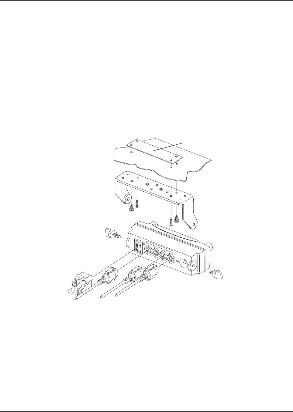
2.2.2.1 Remote Mount Control Head Installation
Choose a mounting location for the radio, considering accessibility, and control and antenna cable
lengths.
The recommended mounting surfaces for the control unit are under the mounting surface, on the
transmission hump, or on the center console. Figure 2-21 and Figure 2-22 shows how the trunnion,
control head, and cables should be installed for the O2, O3, O5, O7 or O9 control head.
NOTE: Connector-protective covers (Remote Mount Dust Cover kit) KT000246A01 are provided with
the radio.
They should be installed on exposed connectors for added environmental robustness.
Before installing any electrical equipment, check the vehicle manufacturer’s user
manual.
The installation of this device should be completed by an authorized servicer or
installer.
Before making any holes in the trunk for radio mounting, check the vehicle
manufacturer's user manual for restrictions (e.g. due to the gas tank location).
!
C a u t i o n
Draft
ng prong pro
2-102-10
or o
FiguFigu
ntrol Head Installatntrol Head Insta
ation for the radio, consideation for the radio, c
rfaces for the controaces for the contro
l unit a
er console. sole.
Figure 2-21Figure 2
an
stalled for the O2, O3, O5alled for the O2, O3, O5
mote Mount Dustmote Mount Dust
Cover kit)
Cover ki
nnenne
ctors for addctors for add
MN003109A01_aa
2-22 Standard Configurations Radio Mounting
An adjustable trunnion, which allows a number of mounting positions, is supplied for mounting the
control unit. The installation must not interfere with the operation of the vehicle or its accessories, nor
disturb passenger seating or leg room. The control head must be within convenient reach and
viewing of the user.
If the trunnion is mounted on a plastic mounting surface, all four mounting screws should penetrate
the mounting surface’s supporting metal frame. If that is not possible, use a metal backing plate (not
supplied) to strengthen the installation. Install the control follows:
1. Use the control unit trunnion as a template to mark the mounting holes; drill 5/32" holes.
If mounting on a plastic surface, use a metal backing plate.
2. Attach the trunnion bracket using all four 10-16" x 5/8" self-tapping screws provided.
3. Temporarily install the control head (adjusting for proper viewing angle) and fasten it to the
trunnion with two wing screws. Test the installation to be sure the control head feels securely
locked in place while you are pressing its buttons.
4. Finish installation by fully tightening screws.
Figure 2-21. O5 Control Head Installation Exploded View (Also applicable for O2 and O7 Control Heads)
Metal Backing Plate
(Not Supplied)
Draft
Draft
t
ft
ft
r
r
aft
aft
aft
aft
aft
af
aft
ft
ft
Draft
Dra
Dr
r
r
Dr
Dr
Dr
Draft
ft
ft
a
r
r
r
r
Dr
Dr
Dr
Dr
a
a
a
a
a
a
D
Dr
a
Dr
Dr
D
D
D
D
D
aft
D
D
aft
aft
aft
aft
aft
aft
aft
aft
aft
aft
aft
aft
aft
aft
aft
aft
aft
aft
aft
aft
aft
aft
aft
aft
aft
aft
aft
aft
aft
af
af
af
raf
af
af
af
af
af
a
aft
a
r
ra
ra
ra
ra
r
r
r
r
r
r
r
r
r
r
r
r
r
r
r
r
r
ra
ra
ra
ra
ra
ra
ra
ra
ra
ra
ra
ra
ra
ra
ra
Dr
Dr
D
Dra
Dr
MN003109A01_aa
Standard Configurations Radio Mounting 2-23
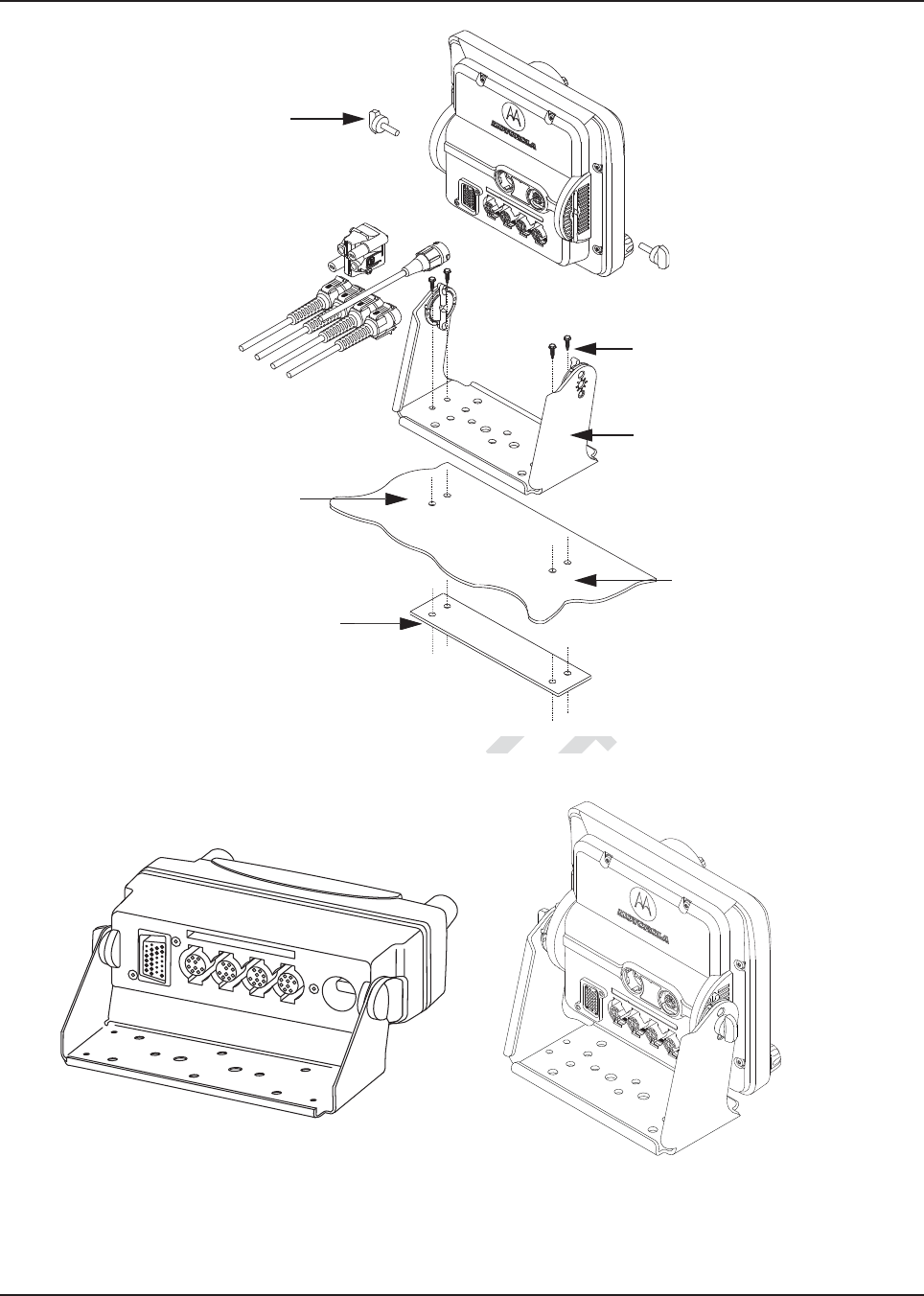
Figure 2-22. O9 Control Head Installation Exploded View
Figure 2-23. O5 and O9 Control Head Rear View
Adjust the control head to desired
angle and secure with wing screws
Use four mounting screws on all
installations
Trunnion
Drill four 5/32” holes in
mounting surface
Mounting surface
IMPORTANT:
Use a metal backing plate (not
supplied) if mounting trunnion on
plastic or unstable surface
r
aft
d Installation Explodnstallation Explo
Draft
a
a
a
ra
f
ra
f
ra
raft
Draft
D
D
Dra
Dr
D
Draf
D
D
D
D
Dr
D
D
D
ra
ra
ra
ra
Dra
D
D
a
a
f
f
f
a
a
D
f
ft
a
D
D
D
f
ra
ra
ra
ra
Dra
f
f
f
f
ft
ft
D
D
r
r
r
r
r
r
ra
r
r
ra
ra
ra
Dr
Dr
Dr
Dra
Dra
Dr
Dra
Dra
Dra
ra
Dra
Dra
ra
ra
ra
ra
ra
ra
ra
ra
ra
ra
ra
ra
ra
ra
ra
ra
ra
ra
f
f
f
f
f
f
f
f
f
f
f
f
ft
ft
ft
ft
ft
ft
ft
ft
ft
f
f
f
f
f
f
f
f
f
f
f
f
ft
ft
ft
ft
ft
ft
ft
ft
ft
ft
ft
ft
D
D
D
D
ra
ra
ra
t
MN003109A01_aa
2-24 Standard Configurations Radio Mounting
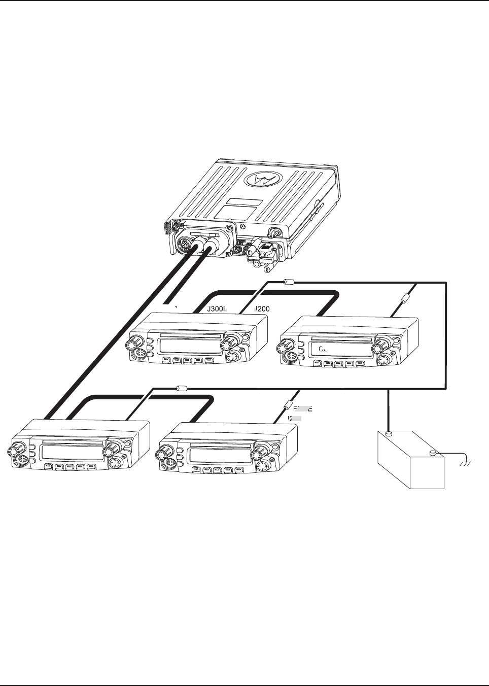
2.2.2.2 Multiple Control Head Installation
Control heads in a multiple control head configuration should be installed per the steps detailed in
Section 2.2.2.1: “Remote Mount Control Head Installation” . Two heads can be connected to each of
the two CAN connectors on the transceiver, see Figure 2-24. Control heads can also be connected a
“daisy chain” configuration from a single transceiver CAN connector. See Figure 2-25 for examples.
NOTE: The transceiver must be configured for Multiple Control Head via CPS programming.
Navigate to the “Control Head” tab in the Radio Wide section of CPS, and select “Help” for
further information and tutorials.
Figure 2-24. Multiple Control Heads Parallel Configurations
Control Head 1 Control Head 2
J300R J300R
J200 J200
J300L
(-)
RED LEAD
(+)
BATTERY
FUSE
FUSE
FUSE
FUSE
Control Head 3 Control Head 4
J300R
J200 J200
J300L
J300R
Draft
D
D
D
D
D
D
D
D
D
D
D
D
D
D
D
D
D
D
D
D
D
D
D
D
D
D
D
D
D
D
D
D
D
D
D
D
D
D
D
D
D
D
D
D
D
D
D
D
D
D
D
D
D
D
D
D
D
D
D
D
D
D
D
D
D
D
D
D
D
D
D
D
D
D
D
D
D
D
D
D
D
D
D
D
D
D
D
D
D
D
D
D
D
D
D
D
D
D
D
D
D
D
D
D
D
D
D
D
D
D
D
D
D
D
D
D
D
D
D
D
D
D
D
D
D
D
D
D
D
D
D
D
D
D
D
D
D
D
D
D
D
D
D
D
D
D
D
D
D
D
D
D
D
D
D
D
D
D
D
D
D
D
D
D
D
D
D
D
D
D
D
D
D
D
D
D
D
D
D
D
D
D
D
D
D
D
D
D
D
D
D
D
D
D
D
D
D
D
D
D
D
D
D
D
D
D
D
D
D
D
D
D
D
D
D
D
D
D
D
D
D
D
D
D
D
D
D
D
D
D
D
D
D
D
D
D
D
D
D
D
D
D
D
D
D
D
D
D
D
D
D
D
D
D
D
D
D
D
D
D
D
D
D
D
D
D
D
D
D
D
D
D
D
D
D
D
D
D
D
D
D
D
D
D
D
D
D
D
D
D
D
D
D
D
D
D
D
D
D
D
D
D
D
D
D
D
D
D
D
D
D
D
D
D
Dr
Dr
D
Dr
Dr
aft
aft
ft
Draf
t
aft
t
t
200
FUSE
ft
ft
ft
ft
Co
J
J300L
D
R
Draf
ra
ra
Dra
ra
ra
ra
ra
ra
ra
ra
ra
ra
ra
r
ra
r
r
r
r
r
ra
a
ra
ra
ra
ra
ra
ra
ra
a
a
a
a
a
a
a
ra
a
a
a
r
r
a
ra
ra
ra
ra
ra
ra
ra
ra
ra
ra
ra
ra
ra
ra
ra
ra
ra
ra
ra
ra
ra
ra
ra
ra
r
r
ra
ra
ra
ra
r
r
ra
r
ra
ra
ra
r
r
ra
ra
ra
ra
ra
ra
ra
ra
ra
ra
ra
ra
r
ra
ra
ra
r
ra
ra
ra
ra
ra
ra
a
a
af
a
f
f
f
f
f
f
f
af
af
af
a
ft
aft
aft
af
af
af
aft
af
af
af
af
af
af
af
af
af
af
af
af
af
ft
ft
f
f
f
ft
f
f
f
f
f
f
f
f
f
f
f
f
f
f
f
f
f
f
f
af
a
af
af
af
af
af
af
af
af
af
af
af
af
af
af
af
af
af
af
af
af
af
af
af
af
af
af
af
af
af
af
af
af
af
af
af
af
af
af
af
af
af
af
af
af
af
af
af
af
af
af
af
af
ft
ft
ft
ft
ft
f
f
ft
ft
ft
ft
ft
ft
ft
f
ft
f
ft
ft
ft
ft
ft
ft
ft
f
ft
f
ft
MN003109A01_aa
Standard Configurations Radio Mounting 2-25
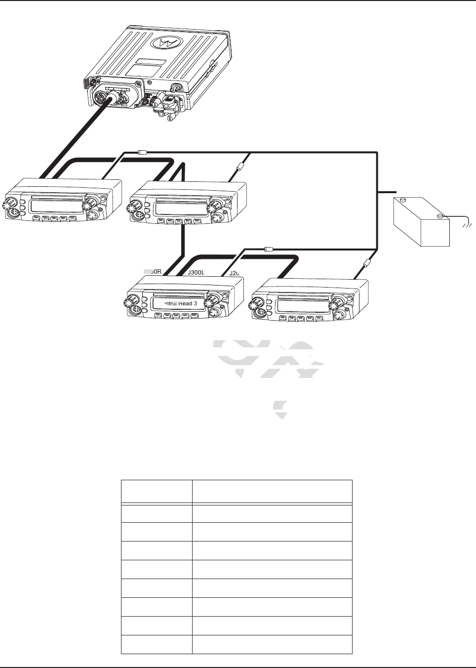
Figure 2-25. Multiple Control Heads Series Configurations
NOTE: In Multiple Control Head (MCH) installations, the yellow ignition sense wire must be
connected to the head assigned ID # 1. Section 2.2.2.4: “Setting the Initial Control Head ID”
for further information.
Use the most convenient configuration for your installation, ensuring that the combined cable lengths
do not exceed 131 feet (40 meters). See Table 2-7 for a list of available CAN cable lengths. Control
head ground, power and ignition sense wires (black, red, and yellow respectively) may need
additional length (not supplied) in installations that locate the head more than 10 feet from a power
source.
Table 2-7. Available CAN Cables
Part Number Description
HKN6164_ Cable, Remote Mount, 40m (131ft)
HKN6165_ Cable, Remote Mount, 35m (115ft)
HKN6166_ Cable, Remote Mount, 23m (75ft)
HKN6167_ Cable, Remote Mount, 15m (50ft)
HKN6168_ Cable, Remote Mount, 9m (30ft)
HKN6169_ Cable, Remote Mount, 5m (17ft)
HKN6170_ Cable, Remote Mount, 3m (10ft)
PMLN4958_ Cable, O3 Extension, 5m (17ft)
Control Head 1 Control Head 2
J300R J300R
J200 J200
J300L J300L
(-)
RED LEAD
(+)
BATTERY
FUSE
FUSE
FUSE
FUSE
Control Head 3 Control Head 4
J300R
J200 J200
J300L
J300R
raft
Control Heads Seontrol Heads Se
ries Conries Co
nstallations, nstallation
the yellow ign
the yellow ig
# 1. 1.
Section 2.2.2.4: “Se
Section 2.2.2.4: “
allation, enation
a lis
a li
Dra
D
D
D
D
Dra
a
D
D
ntrol Hea
L
J300
J30
Dra
r
Dr
ra
Dr
Dr
Dr
Dr
Dr
Dra
Dr
Dra
Dr
Dr
Dr
Dr
Dr
Dr
Dr
Dr
Dr
Dra
Dra
Dra
Dra
Dra
Dr
Dr
Dr
Dra
Dra
Dra
Dra
Dra
Dra
Dra
Dra
Dra
Dra
Dra
Dra
Dr
Dr
r
ra
ra
Dr
Dra
Dr
Dr
Dr
D
Dr
Dr
D
r
D
r
D
D
D
D
Dr
Dr
Dr
r
r
Dr
Dr
r
Dr
r
Dr
Dr
Dr
Dr
Dr
Dr
Dr
Dr
Dr
Dr
Dr
Dr
Dr
Dr
Dr
Dr
Dra
Dr
Dr
Dr
Dr
Dr
Dr
Dr
Dr
Dr
Dr
Dr
Dr
Dr
Dr
Dr
Dr
Dr
Dr
Dr
Dr
Dr
Dr
Dr
Dr
Dr
Dr
Dr
Dr
Dr
Dr
Dr
Dr
Dr
Dr
Dr
Dr
Dr
Dr
Dr
Dr
Dr
Dr
Dr
Dr
Dr
Dr
Dr
Dr
Dr
a
a
a
a
a
a
a
a
a
a
a
a
a
a
a
a
a
a
a
a
a
a
a
a
a
a
a
a
a
a
a
a
a
a
a
a
a
a
a
a
a
a
a
a
a
a
a
a
a
a
a
a
a
a
a
a
a
a
a
a
a
a
a
MN003109A01_aa
2-26 Standard Configurations Radio Mounting
2.2.2.3 Cable Installation
Route the cables where they are protected from pinching, sharp edges or crushing. Use grommets in
any holes where the cable passes through metal panels. Figure 2-15 shows how the cables and
components are connected. It is not recommended to route cabling or wiring inside the wheel wells
of a vehicle.
2.2.2.4 Setting the Initial Control Head ID
The Front Panel Programming (FPP) mode allows you to define which control head in a Multi Control
Head system becomes control head number 1-4.
Set the control head ID number for each attached head the first time Multi Control Head is used.
1. Press the power button to power off the radio.
2. Press and hold left-most menu and the orange button on the control head simultaneously.
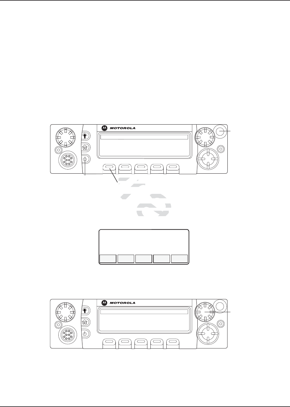
Figure 2-26. APX Mobile O5 Control Head Front View
3. Press the power button to power on the control head. The head will power on into FPP mode
and display the current control head ID number:
Figure 2-27. Radio Display with Current Control Head ID
4. Turn the Mode knob to change the control head’s ID number.
Figure 2-28. APX Mobile O5 Control Head Front View – Mode Knob
5. Repeat steps 1 to 4 above to set the ID of the remaining control heads.
NOTE: In Multiple Control Head (MCH) installations, the yellow ignition sense wire must be
connected to the head assigned ID # 1.
O5
Left-most
Menu Button
Power Button
Emergency
Button
CH ID#
1
O5
Mode Knob
Draft
X Mobile O5Mob
Control HeadContro
5
er on the control head. Thethe control h
ad ID number:d ID number:
D
D
D
D
D
D
D
D
D
D
D
D
D
D
D
D
D
D
D
D
D
Left-most Left-most
Menu ButtonMenu Button
D
aft
aft
t
t
MN003109A01_aa
Standard Configurations Radio Mounting 2-27
2.2.2.5 O3 Control Head and Remote Mount Cabling
Choose a mounting location for the radio, considering accessibility, and control and antenna cable
lengths. The control head extension cable and the accessories cable should be installed and routed
properly to avoid complications. Route the cables in the vehicle’s wiring troughs (where available) or
route the cables where they are protected from pinching, sharp edges, or crushing. One suggested
route is along one side of the driveshaft hump under the carpet. Use grommets in any holes where
the cable passes through metal panels.
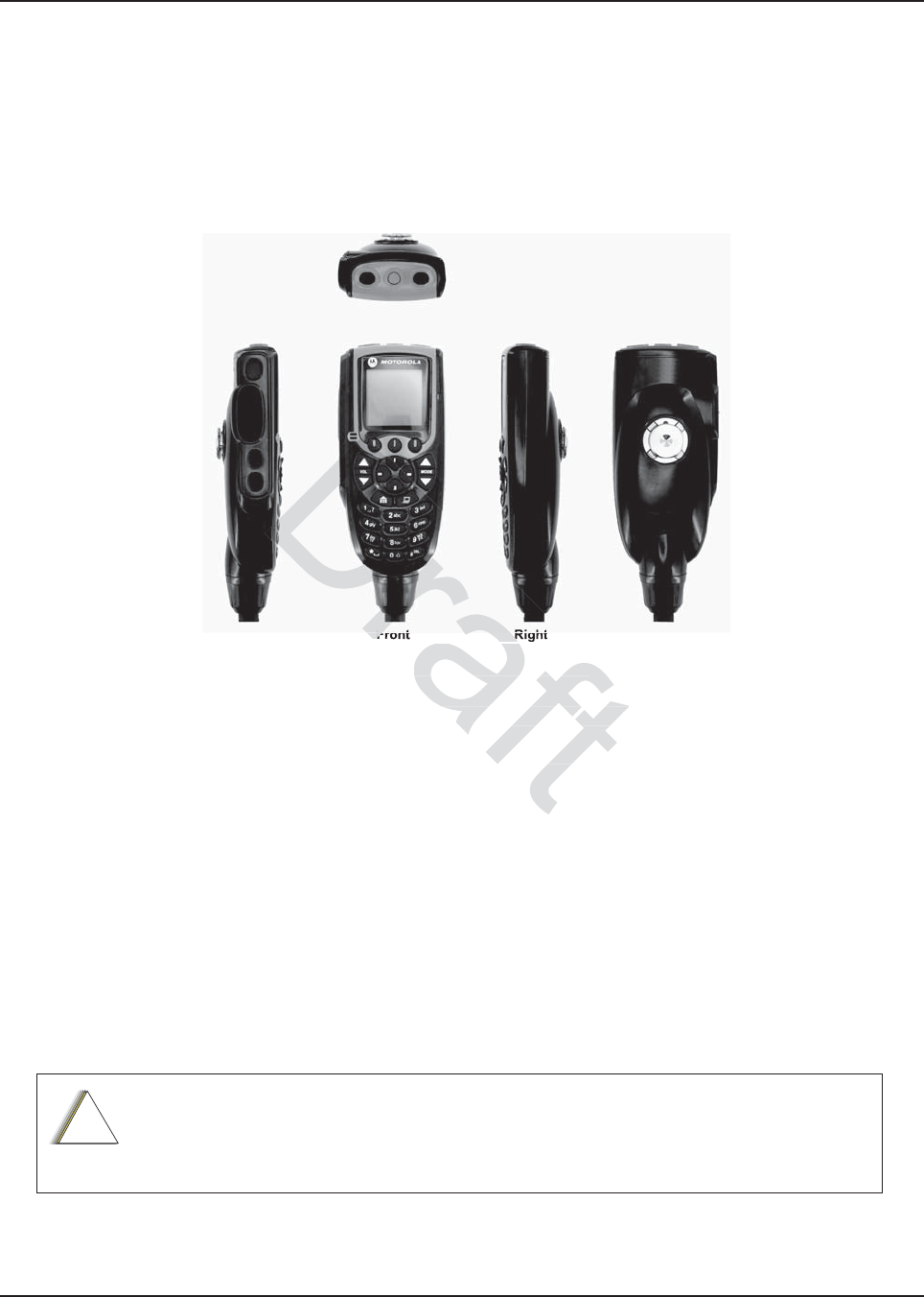
Figure 2-29. O3 Control Head
The recommended mounting surface for the control unit is on the center console. Figure 2-31 shows
how the hang-up clip control head, and cables should be installed for the O3 control head.
NOTE: Connector-protective covers are provided with the radio. They should be used for added
environmental robustness.
A mounting clip, which allows the control head to be mounted, is supplied together with the control
head. The installation must not interfere with the operation of the vehicle or its accessories, nor
disturb the passenger seating. The control head must be within convenient reach and viewing of the
user.
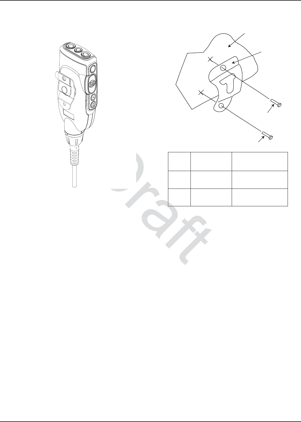
Install the mounting clip as follows:
1. Use the provided mounting clip to determine the location of the two screw holes.
2. Drill 7/16” deep holes for upper and lower screws.
3. Use the tapping screw provided to install the mounting clip.
Care must be taken to shield the control head (front and back) from direct exposure to
pressurized water. The pressurized water from a hose, in most cases, is more severe
than the stated test and conditions in typical environments.
Top
Front RightLeft Back
!
C a u t i o n
2-29. O3 Control Head29. O3 Control Head
the control unit is on the ce
the control unit is on the c
les s
should be installed fo
should be installed
ed with the radio.d with the radio
ou
ou
raf
Front R
Front
MN003109A01_aa
2-28 Standard Configurations Radio Mounting
Figure 2-30. O3 Control Head Rear View Figure 2-31. Hang-Up Clip Installation Exploded
View
VEHICLE
DASHBOARD
2
2
1
2
2
1
Vehicle Mounting Surface
Item
No.
Part Number Description
1 01-80743T91 Mic Hang-Up Clip
Assembly
2 03-07644M19 Screw, Machine,
8-32 x 7/16
View FigurewFigure
2-31. Ha2-31. Ha
Dr
2
a
a
MN003109A01_aa
Standard Configurations Radio Mounting 2-29
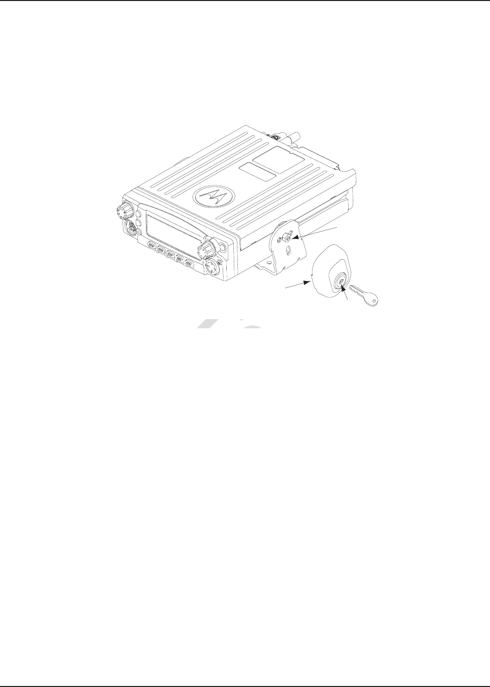
2.2.3 Locking Kit (Optional)
2.2.3.1 All Radios
If an optional locking kit (HLN6372_) is used (shown in Figure 2-32), position the lock housing on the
trunnion after installing the radio mounting screws. Then rotate the lock with the key in it and remove
the key to lock the radio. You can install the lock on either side of the radio, and in dash and remote
mount installations.
Figure 2-32. Locking Kit (Optional)
Lock
Lock
Housing
Existing
Mounting
Screw
Draft
gure 2-32. Locking Kit (Op2-32. Locking
Dr
D
D
D
D
D
D
D
D
D
D
D
D
D
D
D
D
D
D
D
D
D
D
D
D
D
D
D
D
D
D
D
D
D
D
D
D
D
D
D
D
D
D
D
D
D
D
D
D
D
D
D
D
D
D
D
D
D
D
D
D
D
D
D
D
D
D
D
D
D
D
D
D
D
D
D
D
D
D
D
D
D
D
D
D
D
D
D
D
D
D
D
D
D
D
D
D
D
D
D
D
D
D
D
D
D
D
D
D
D
D
D
D
D
D
D
D
D
D
D
D
D
D
D
D
D
D
D
D
D
D
D
D
D
D
D
D
D
D
D
D
D
D
D
D
D
D
D
D
D
D
D
D
D
D
D
D
D
D
D
D
D
D
D
D
D
D
D
D
D
D
D
D
D
D
D
D
D
D
D
D
D
D
D
D
D
D
D
D
D
D
D
D
D
D
D
D
D
D
D
D
D
D
D
D
D
D
D
D
D
D
D
D
D
D
D
D
D
D
D
D
D
D
D
D
D
D
D
D
D
D
D
D
D
D
D
D
D
D
D
D
D
D
D
D
D
D
D
D
D
D
D
D
D
D
D
D
D
D
D
D
D
D
D
D
D
D
D
D
D
D
D
D
D
D
D
D
D
D
D
D
D
D
D
D
D
D
D
D
D
D
D
D
D
D
D
D
D
D
D
D
D
D
D
D
D
D
D
D
D
D
D
D
D
D
D
D
D
D
D
D
D
D
D
D
D
D
D
D
D
D
D
D
D
D
D
D
D
D
D
D
D
D
D
D
D
D
D
D
D
D
D
D
D
D
D
D
D
D
D
D
D
D
D
D
D
D
D
D
D
D
D
D
D
D
D
D
D
D
D
D
D
D
D
D
D
D
D
D
D
D
D
D
D
D
D
D
D
D
D
D
D
D
D
D
D
D
D
D
D
D
D
D
D
D
D
D
D
D
D
D
D
D
D
D
D
D
D
D
D
D
D
D
D
D
D
D
D
D
D
D
D
D
D
D
D
D
D
D
D
D
D
D
D
D
D
D
D
D
D
D
D
D
D
D
D
D
D
D
D
D
D
D
D
D
D
D
D
D
D
D
D
D
D
D
D
D
D
D
D
D
D
D
D
D
D
D
D
D
D
D
D
D
D
D
D
D
D
D
D
D
D
D
D
D
D
D
D
D
D
D
D
D
D
D
D
D
D
D
D
D
D
D
D
D
D
D
D
D
D
D
D
D
D
D
D
D
D
D
D
D
D
D
D
D
D
D
D
D
D
D
D
D
D
D
D
D
D
D
D
D
D
D
D
D
D
D
D
D
D
D
D
D
D
D
D
D
D
D
D
D
D
D
D
D
D
D
D
D
D
D
D
D
D
D
D
D
D
D
D
D
D
D
D
D
D
D
D
D
D
D
D
D
D
D
D
D
D
D
D
D
D
D
D
D
D
D
D
D
D
D
D
D
D
D
D
D
D
D
D
D
D
D
D
D
D
D
D
D
D
D
D
D
D
D
D
D
D
D
D
D
D
D
D
D
D
D
D
D
D
D
D
D
D
D
D
D
D
D
D
D
D
D
D
D
D
D
D
D
D
D
D
D
D
D
D
D
D
D
D
D
D
D
D
D
D
D
D
D
D
D
D
D
D
D
D
D
D
D
D
D
D
D
D
D
D
D
D
D
D
D
D
D
D
D
D
D
D
D
D
D
D
D
D
D
D
D
D
D
D
D
D
D
D
D
D
D
D
D
D
D
D
D
D
D
D
D
D
D
D
D
D
D
D
D
D
D
D
D
D
D
D
D
D
D
D
D
D
D
D
D
D
D
D
D
D
D
D
D
D
D
D
D
D
D
D
D
D
D
D
D
D
D
D
D
D
D
D
D
D
D
D
D
D
D
D
D
D
D
D
D
D
D
D
D
D
D
D
D
D
D
D
D
D
D
D
D
D
D
D
D
D
D
D
D
D
D
D
D
D
D
D
D
D
D
D
D
D
D
D
D
D
D
D
D
D
D
D
D
D
D
D
D
D
D
D
D
D
D
D
D
D
D
D
D
D
D
D
D
D
D
D
D
D
D
D
D
D
D
D
D
D
D
MN003109A01_aa
2-30 Standard Configurations Power Cables (Transceiver and Control Head)
2.3 Power Cables (Transceiver and Control Head)
Route the RED power cable from both the radio and the control head to the vehicle’s battery
compartment, using accepted industry methods and standards. Be sure to grommet the firewall hole
to protect the cable. Remove the 15-amp (part number 6580283E06), 20-amp (part number
6580283E07) or 30-amp (part number 6580283E09) fuse from the fuseholder and connect the red
lead of the radio power cable to the positive battery terminal using the hardware provided as shown
in Figure 2-33 and Figure 2-34. Connect the black lead to a convenient solid chassis ground point.
DO NOT connect the black lead directly to the battery’s negative terminal.
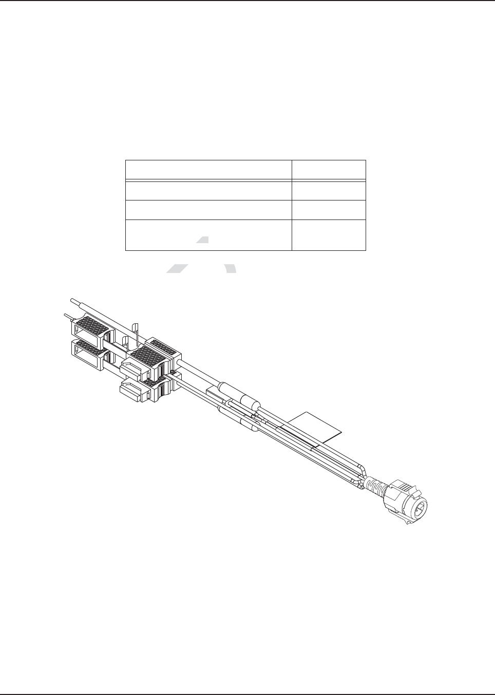
2.3.1 O2, O5, O7 or O9 Control Head Power Cables
Figure 2-33. HKN6188_ Power Cable with External Speaker Connector
Table 2-8. Power Cables
Description Part Number
Mid Power Dash Mount HKN4191_
Mid Power Remote Mount HKN4192_
O5, O7, and O9 Remote Control
Head Power Cable
HKN6188_
Dr
trol Head Powtrol Head Po
ableable
D
Draft
t
t
ft
ft
MN003109A01_aa
Standard Configurations Power Cables (Transceiver and Control Head) 2-31
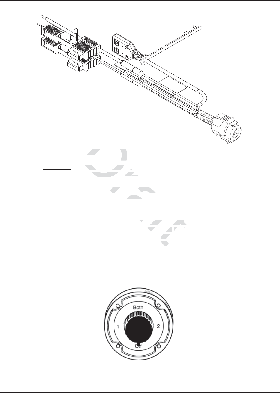
Figure 2-34. HKN6187_ Power Cable with External Speaker Connector, Record Audio Output Jack (2.5 mm)
and Earphone Jack (2.5 mm)
NOTE: Audio Out – Does not require CPS programming. Attaching a headset will mute the external
speakers of the radio which are attached at the SPK jack of the control head.
Record Out – Requires CPS programming. In CPS, navigate to Radio Wide/Advanced/
Record Audio and select TX + RX Audio.
2.3.2 Battery Selector Switch
In vehicles which have installed a Battery Selector Switch, the ignition sense (yellow) wire should be
the only wire connected to the battery selector switch (see Figure 2-35). Radio transceiver and
control head power wires (red) must be connected directly to the vehicle battery. If the control head
power wire and the control head ignition sense wire are both connected to a battery selector switch,
but the radio transceiver power lead is not, improper power-cycling and off-state battery drainage
may occur. If the desired state of the radio is a total battery drain elimination, then all power and
ignition sense wires must be routed through the battery selector switch, so that the control head and
radio transceiver both see the loss of battery power at the same time.
Figure 2-35. Battery Selector Switch
Draft
able with External Sable with Externa
and Earphone rph
oes not require CPS prograoes not require CPS
dio whicdio whic
h are attached at h are attach
CPS programming. In CCPS programming.
P
X + RX Audio.X Audi
ector Switch, the ignit
ector Switch, the ig
switch (see witch (see
FigurFigur
di
rectly to ectly
re bore b
D

MN003109A01_aa
2-32 Standard Configurations Antenna Installation
2.4 Antenna Installation
IMPORTANT: To assure optimum performance and compliance with RF Energy
Exposure regulations, these antenna installation guidelines and
instructions are limited to metal-body vehicles with appropriate ground
planes and take into account the potential exposure of back seat
passengers and bystanders outside the vehicle.
2.4.1 Selecting an Antenna Site/Location on a Metal Body Vehicle
1. External installation – Check the requirements of the antenna supplier and install the
vehicle antenna external to a metal body vehicle in accordance with those requirements.
2. Roof top – For optimum performance and compliance with RF Energy Exposure regulations,
mount the antenna in the center area of the roof.
3. Trunk lid – On some vehicles with clearly defined, flat trunk lids, the antennas of some radio
models (see restrictions below) can also be mounted on the center area of the trunk lid. For
vehicles without clearly defined, flat trunk lids (such as hatchback autos, sports utility
vehicles, and pick-up trucks), mount the antenna in the center area of the roof.
Before installing an antenna on the trunk lid,
- Be sure that the distance from the antenna location on the trunk lid will be at least 85 cm
(33 inches) from the rear seat head-rest to ensure compliance with RF Energy Exposure
regulations.
- Ensure that the trunk lid is grounded by connecting grounding straps between the trunk lid
and the vehicle chassis.
4. Mounting restrictions for certain radio models.
NOTE: Do not cut antenna cables to ensure compliance with RF Energy Exposure regulations
NOTE: VHF and UHF 1/4 wave antenna should be mounted only in the center area of the roof,
not on the trunk lid, to ensure compliance with RF Energy Exposure regulations.
5. Ensure that the antenna cable can be easily routed to the radio. Route the antenna cable as
far away as possible from any vehicle electronic control units and associated wiring.
6. Check the antenna location for any electrical interference.
NOTE: Any two metal pieces rubbing against each other (such as seat springs, shift levers, trunk and
hood lids, exhaust pipes, etc.) in close proximity to the antenna can cause severe receiver
interference.
If these conditions cannot be satisfied, then mount the antenna on the roof top.
!
C a u t i o n
ft
s.s.
Draft
, m
, m
tenna on ttenna on
stance from the anstance from the
m the rear seat head-rest
m the rear seat hea
k lid is grounded by conk lid is grounded by
ne
s
d
then mount the antenn
then mount the ante
raf
ft
MN003109A01_aa
Standard Configurations Antenna Installation 2-33
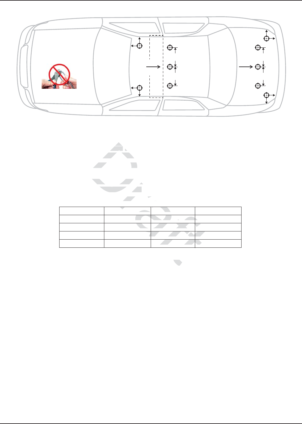
Figure 2-36. Multiple Antennas Separation for locations 1-10
Figure 2-36 indicates the separation distances required for the various antennas used with an APX
8500 midpower radio. Each "cross-hair" symbol represents a possible location (i.e. LOC) of an
antenna. The recommendation is to locate them as close to the center of the roof and/or trunk as
possible, without interference with a lightbar. This picture is not drawn to scale.
For letters A, B, C, and D, the table indicates the EXACT distance for separation of the LMR
antennas.
For letters E, F, G, and H, the table indicates the maximum distance between the edge of the ground
plane and the accessory antenna location.
NOTE:
• A minimum of 18 inch separation is required between lightbar and any roof mounted antennas,
to prevent interference with the lightbar circuitry (see lightbar manufacturers installation
information).
• The LMR 700/800 antennas should only be placed at LOC:2 or LOC:5.
• Standard LMR VHF and UHF antennas should only be placed at LOC:1, LOC:3, LOC:4 and
LOC:6.
• 1/4 wave LMR VHF and UHF antennas should only be placed at LOC:1 and LOC:3 (i.e.roof
only) to ensure compliance with RF Energy Exposure regulations.
• The VML antenna must be separated from any LMR antenna by at least 40 inches.
• The LTE Main and Diversity Antenna locations should be at LOC:9 and LOC:10 when the LMR
All-Band or LMR 700/800 narrow band antennas are at LOC:2 (i.e LTE opposite location from
the LMR).
• The LTE Main and Diversity Antenna locations should be at LOC:7 and LOC:8 when the LMR
All-Band or LMR 700/800 narrow band antennas are at LOC:5 (i.e LTE opposite location from
the LMR).
• In some mobile installations that include an LTE modem, external filtering on the LMR port and/
or the LTE port may be needed to reduce interference. Contact your local Motorola Solutions
Service Center for more information and for filter kit numbers (See Appendix for contact info).
Table 2-1 Distance Between Antenna
Characters Distance Characters Distance
A 8 inches E 8 inches
B 8 inches F 8 inches
C 8 inches G 8 inches
D 8 inches H 8 inches
F
F
E
G
C
D
G
H
H
E
LOC:7 LOC:1
LOC:2
LOC:3
A
B
LOC:8
LOC:9
LOC:4
LOC:5
LOC:6
LOC:10
Roof
Center
Trunk
Center
NOTE: Do not cut
the antenna cable
ft
ween wee
ft
aft
H8H
ft
aft
G8
G
a
ft
aft
es F 8
es F
a
ft
Draf
ss-h
ss-h
is to is to
lolo
e with a lighte with a ligh
D, the table indicaD, the table indica
te
H, the table indicates tH, the table indicate
he m
ntenna location. ntenna location.
istance Between Antennace Between A
istance Charactersstance Char
ches Ees E
ra
f
ra
raf
af
aft
aft
ft
MN003109A01_aa
2-34 Standard Configurations Antenna Installation
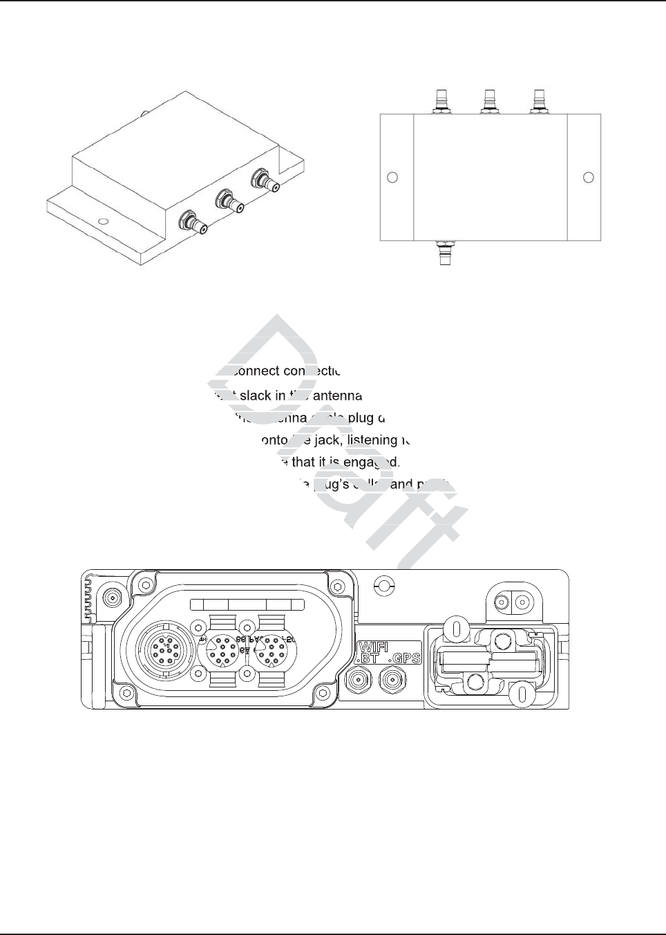
2.4.2 Multiplexers and Vehicle Installation
Figure 2-37. Multiplexer Views
2.4.3 QMA Connection (APX8500 Only)
APX8500 is using a quick disconnect connection called QMA. This does not require any tightening.
• Ensure there is sufficient slack in the antenna cable.
• Ensure that the collar of the antenna cable plug does not bind.
• Engage the QMA cable plug onto the jack, listening for a click to ensure proper engagement.
• Gently tug on the cable to ensure that it is engaged.
• To disengage, pull back on the cable plug’s collar and pull the cable straight off the jack.
2.4.4 GPS/GLONASS/Wi-Fi/Antenna Placement (APX8500 Only)
Figure 2-38. GPS/GLONASS and Wi-Fi Antenna Connector on the Back of the Mid Power Radio
D
Dr
Dr
Dra
raf
raf
8500 Only)8500 Only)
disconnect conne
cient slack in the
the antenna cable p
o the jack, liste
re that it is engaged
plug’s collar and pull the
ement (APX8500 On
ement (APX8500 O
t
t
MN003109A01_aa
Standard Configurations Speaker 2-35
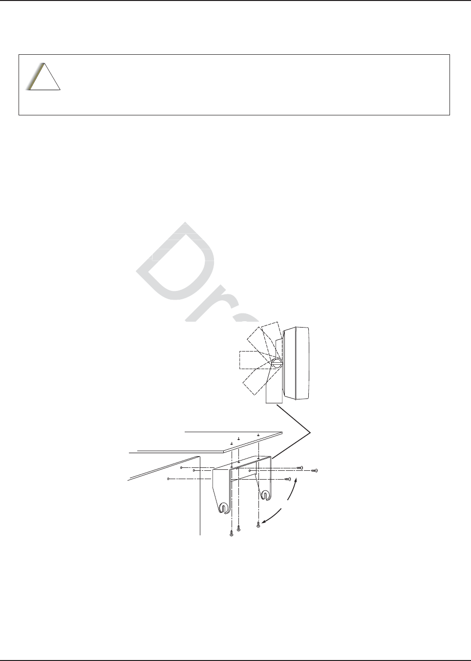
2.5 Speaker
The speaker kit includes a trunnion bracket that allows the speaker to be mounted in a variety of
ways. With the trunnion bracket, the speaker can mount permanently on the mounting surface or in
accessible firewall areas. The trunnion allows the speaker to tilt for best operation. Mount the
speaker out of the way so that it will not be kicked or knocked around by the vehicle occupants.
Mount the speaker as follows:
1. Use the speaker mounting bracket as a template to mark the mounting hole locations.
2. Use the self-drilling screws provided to fasten the trunnion.
3. Attach the speaker and fasten to the trunnion with two wing screws.
4. Route the speaker wires under the carpet or floor covering, or behind the kick panels. Be sure
the wires are out of the way and will not be snagged and broken by the occupants of the
vehicle.
5. Do not submerse the 2-pin speaker connector in water nor place this connector in an area
that could have standing water.
Figure 2-39. Speaker Mounting
DO NOT ground the radio's speaker leads. This system has a floating speaker output
(DC voltage on both leads); damage to the audio circuit will result if either lead is
grounded or if they are shorted together.
!
C a u t i o n
Dashboard
Firewall
Trunnion
Bracket
OR
fastenfasten
ires under theires under th
ofof
the way and will the way and w
ff
e the 2-pin speaker connec the 2-pin speaker
nding water.nding wate
raft
ft
ft
ft
ft
aft
ft
aft
aft
aft
aft
raft
ft
ft
t
MN003109A01_aa
2-36 Standard Configurations Speaker
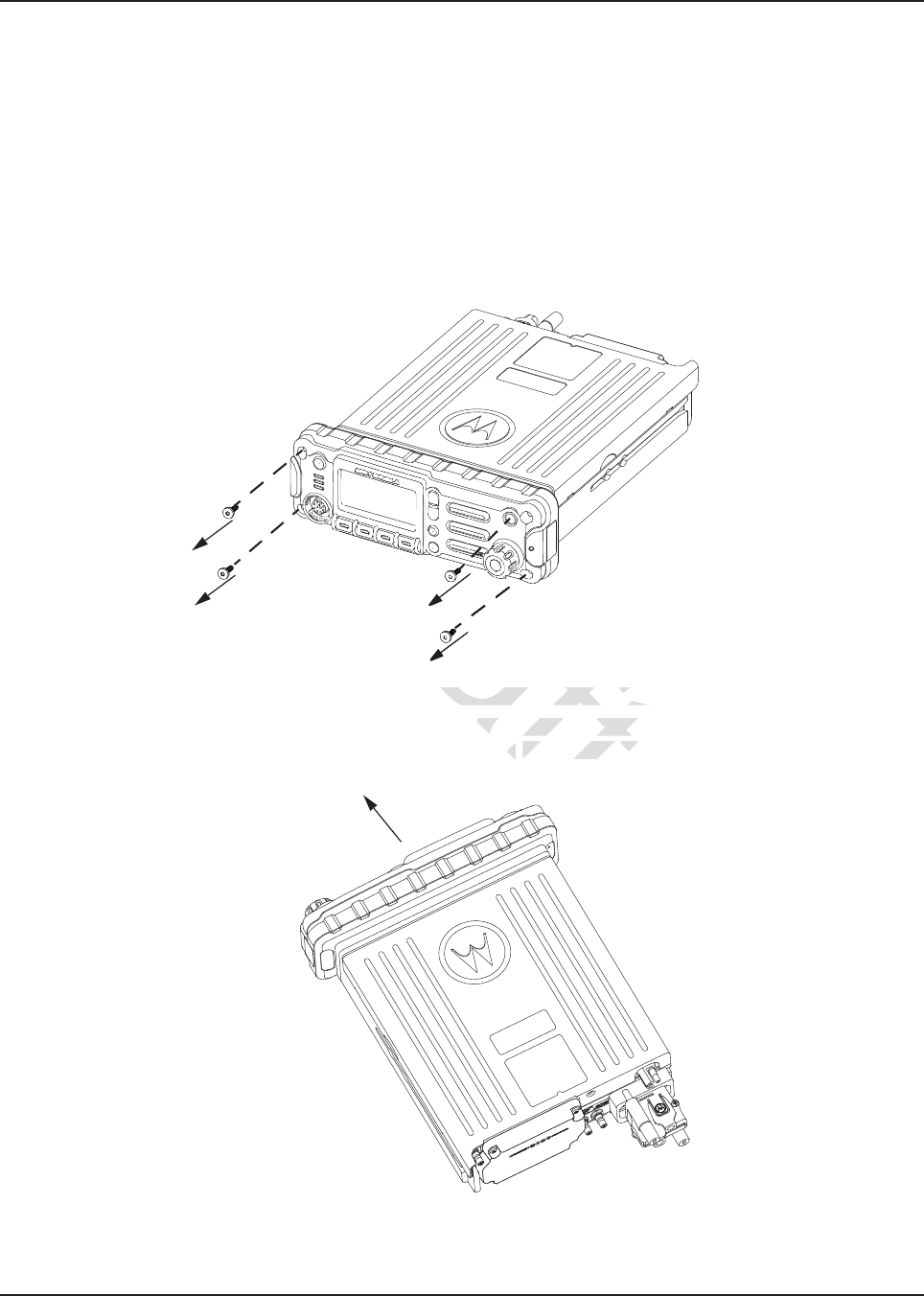
2.5.1 Internal Speaker Disassembly
NOTE: This configuration is only applicable for O2 Control Heads.
You can disable the internal speaker of your radio by following the instructions below.
Use the following procedure to disassemble your radio:
1. Unplug power, antenna, microphone and all accessories connections. If the radio is a
remote-mount radio, disconnect the remote-mount control cable from the front of the
transceiver.
2. Remove the four screws found on the control head with a Torx T-20 bit as shown in
Figure 2-40. Discard the screws.
Figure 2-40. Removing the screws on the Control Head
3. Firmly grasp the front panel of the control head. Carefully remove the front housing assembly
from the back housing assembly as shown in Figure 2-41. Note the position of the attached
flex and do not pull on it excessively.
Figure 2-41. Removing the Control Head
aft
he screws on the Control H
he screws on the Control
ol head. Carefully remov
l head. Carefully rem
n in n
Figure 2-41Figure 2-41
. NN
raf
Draf
Dra
Dr
Dr
Dr
D
Dr
D
D
D
D
D
D
D
D
D
D
D
D
D
D
D
D
D
D
D
D
D
D
D
D
D
D
D
D
D
D
D
D
D
D
D
D
D
D
D
D
D
D
D
D
D
D
D
D
D
D
D
D
D
D
D
D
D
D
D
D
D
D
D
D
D
D
D
D
D
D
D
D
D
D
D
D
D
D
D
D
D
D
D
D
D
D
D
D
D
D
D
D
D
D
D
D
D
D
Dr
D
D
D
D
D
D
D
D
D
D
D
D
D
D
D
D
D
D
D
D
D
D
D
D
D
D
D
D
D
D
D
D
D
D
D
D
D
D
D
D
D
D
D
D
D
D
D
D
D
D
D
D
D
D
D
D
D
D
D
D
D
D
D
D
D
D
D
D
D
D
D
D
D
D
D
D
D
D
D
D
D
D
D
D
D
D
D
D
D
D
D
D
D
D
D
D
D
r
D
D
D
D
D
D
D
D
D
D
D
D
D
D
D
D
D
D
D
D
D
D
D
D
D
D
D
D
D
D
D
D
D
D
D
D
D
D
D
D
D
D
D
D
D
D
D
D
D
D
D
D
D
D
D
D
D
D
D
D
D
D
D
D
D
D
D
D
D
D
D
D
D
D
D
D
D
D
D
D
D
D
D
D
D
D
D
D
D
D
D
D
D
D
D
D
D
D
D
D
r
r
r
r
r
D
r
r
r
r
r
r
r
r
D
D
D
D
D
D
D
D
D
D
D
D
D
D
D
D
D
D
D
D
D
D
D
D
D
D
D
D
D
D
D
D
D
D
D
D
D
D
D
D
D
D
D
D
D
D
D
D
D
D
D
D
D
D
D
D
D
D
D
D
D
D
r
r
D
D
D
D
D
D
D
D
D
D
D
D
D
D
D
D
D
D
D
D
D
D
D
D
D
D
D
D
D
D
D
D
D
D
D
D
D
D
r
r
r
r
r
r
r
r
r
D
D
D
D
D
D
D
D
D
D
D
D
D
D
D
D
D
D
D
D
D
r
r
r
D
D
D
D
D
D
D
D
D
r
D
D
D
D
D
D
D
D
D
D
D
D
D
D
D
D
D
D
D
D
D
D
D
D
D
D
D
D
D
D
D
D
D
D
D
D
D
D
D
D
D
D
D
D
D
D
D
D
D
D
D
D
D
D
D
D
D
D
D
D
D
D
D
D
D
D
D
D
D
D
D
D
D
D
D
D
D
D
D
D
D
D
D
D
D
D
D
D
D
D
D
D
D
D
D
D
D
D
D
D
D
D
D
D
D
D
D
D
D
D
D
D
D
D
D
D
D
D
D
D
D
D
D
D
D
D
D
D
D
D
D
D
D
D
D
D
D
D
D
D
D
D
D
D
D
D
D
D
D
D
D
D
D
D
D
D
D
D
D
D
D
D
D
D
D
D
D
D
D
D
D
D
D
D
D
D
D
D
D
D
D
D
D
D
D
D
D
D
D
D
D
D
D
D
D
D
D
D
D
D
D
D
D
D
D
D
D
D
D
D
D
D
D
D
D
D
D
D
D
D
D
D
D
D
D
D
D
D
D
D
D
D
D
D
D
D
D
D
D
D
D
D
D
D
D
D
D
D
D
D
D
D
D
D
D
D
D
D
D
D
D
D
D
D
D
D
D
D
D
D
D
D
D
D
D
D
D
D
D
D
D
D
D
D
D
D
D
D
D
D
D
r
r
r
r
r
r
r
r
r
r
r
D
D
D
D
D
D
D
D
D
D
D
D
D
D
D
D
D
D
D
D
D
D
D
D
D
D
D
D
D
D
D
D
D
D
D
D
D
D
D
D
D
D
D
D
D
D
D
D
D
D
D
D
D
D
D
D
D
D
D
D
D
D
D
D
D
D
D
D
D
D
D
D
r
r
r
D
D
D
D
D
D
D
D
D
D
D
D
D
D
D
D
D
D
D
D
D
D
D
D
D
D
D
D
D
D
D
D
D
D
D
Dr
D
D
D
D
D
D
D
D
D
D
D
D
D
D
D
D
D
D
Dr
Dr
D
D
D
D
D
D
D
D
D
D
D
D
D
D
D
D
D
D
D
D
D
D
D
D
D
D
D
D
D
D
D
D
D
D
D
D
D
D
D
D
D
D
D
D
D
D
D
D
D
D
D
D
D
D
D
D
D
D
D
D
D
D
D
D
D
D
D
D
D
D
D
D
D
D
D
D
D
D
D
D
D
D
D
D
D
D
D
D
D
D
D
D
D
D
D
D
D
D
D
D
D
D
D
D
D
D
D
D
D
D
D
D
D
D
D
D
D
D
D
D
D
D
D
D
D
D
D
D
D
D
D
D
D
D
D
D
D
D
D
D
D
D
D
D
D
r
D
D
D
D
D
D
D
Dr
D
D
D
D
D
D
D
D
D
D
D
D
D
D
D
D
D
D
D
D
D
D
D
D
D
D
D
D
D
D
D
D
D
D
r
r
r
r
D
D
D
D
D
D
D
D
D
r
D
D
D
D
D
D
D
D
D
D
D
D
D
D
D
D
D
D
D
D
D
D
D
D
D
D
D
D
D
D
D
D
D
D
D
D
D
D
D
D
D
D
D
D
D
D
D
D
D
D
D
D
D
D
D
D
D
r
r
r
D
D
D
D
D
D
D
D
D
D
D
D
D
D
D
D
D
D
D
D
D
D
D
D
D
D
D
D
D
D
D
D
D
D
D
D
D
D
D
D
D
D
D
D
D
D
D
D
D
D
D
D
D
D
D
D
D
D
D
D
D
D
D
D
D
D
D
D
D
D
D
D
D
D
D
D
D
D
D
D
D
D
D
D
D
D
D
D
D
D
D
D
D
D
D
D
D
D
D
D
D
D
D
D
D
D
D
D
D
D
D
D
D
D
D
D
D
D
D
D
D
D
D
D
D
D
D
D
D
D
D
D
D
D
D
D
D
D
D
D
D
D
D
D
D
D
D
D
D
D
D
D
D
D
D
D
D
D
D
D
D
D
D
D
D
D
D
D
D
D
D
D
D
D
D
D
D
D
D
D
D
D
D
D
D
D
D
D
D
D
D
D
D
D
D
D
D
D
D
D
D
D
D
D
D
D
D
D
D
D
D
D
D
D
D
D
D
D
D
r
D
r
D
r
r
D
r
r
r
D
D
D
D
D
D
D
D
D
D
D
D
D
D
D
D
D
D
D
D
D
D
D
D
D
D
D
D
D
D
D
D
D
D
D
D
D
D
D
D
D
D
D
D
D
D
D
D
D
D
D
D
D
D
D
D
D
D
D
D
D
D
D
D
D
D
D
D
D
D
D
D
D
D
D
D
D
D
D
D
D
D
D
D
D
D
D
D
D
D
D
D
D
D
D
D
D
D
D
D
D
D
D
D
D
D
D
D
D
D
D
D
D
D
D
D
D
D
D
D
D
D
D
D
D
D
D
D
D
D
D
D
D
D
D
D
D
D
D
D
D
D
D
D
D
D
D
D
D
D
D
D
D
D
D
D
D
D
D
D
Dr
Dr
Dr
Dr
Dr
Dr
Dr
Dr
Dr
Dr
Dr
Dr
Dr
Dr
Dr
Dr
Dr
Dr
Dr
Dr
Dr
Dr
Dr
Dr
Dr
Dr
Dr
Dr
Dr
Dr
Dr
Dr
Dr
Dr
Dr
Dr
Dr
Dr
Dr
Dr
Dr
Dr
Dr
Dr
Dr
Dr
Dr
Dr
Dr
Dr
Dr
Dr
Dr
Dr
Dr
Dr
Dr
Dr
Dr
Dr
Dr
Dr
Dr
Dr
Dr
Dr
Dr
Dr
Dr
Dr
Dr
Dr
Dr
Dr
Dr
Dr
Dr
Dr
Dr
Dr
Dr
Dr
Dr
Dr
Dr
Dr
Dr
Dr
Dr
Dr
Dr
Dr
Dr
Dr
Dr
Dr
Dr
Dr
Dr
Dr
Dr
Dr
Dr
Dr
Dr
Dr
Dr
Dr
Dr
Dr
Dr
Dr
Dr
Dr
Dr
Dr
Dr
Dr
Dr
Dr
Dr
Dr
Dr
Dr
Dr
Dr
Dr
Dr
Dr
Dr
Dr
Dr
Dr
Dr
Dr
Dr
Dr
Dr
Dr
Dr
Dr
Dr
Dr
Dr
Dr
Dr
Dr
Dr
Dr
Dr
Dr
Dr
Dr
Dr
Dr
Dr
Dr
Dr
Dr
Dr
Dr
Dr
Dr
Dr
Dr
Dr
Dr
Dr
Dr
Dr
Dr
Dr
Dr
Dr
Dr
Dr
Dr
Dr
Dr
Dr
Dr
Dr
Dr
Dr
Dr
Dr
Dr
Dr
Dr
Dr
Dr
Dr
Dr
Dr
Dr
Dr
Dr
Dr
Dr
Dr
Dr
ra
ra
ra
ra
ra
ra
ra
ra
ra
ra
ra
ra
ra
ra
ra
ra
ra
ra
ra
ra
ra
ra
ra
ra
ra
ra
ra
ra
ra
ra
ra
ra
ra
ra
ra
ra
ra
ra
ra
ra
ra
ra
ra
ra
ra
ra
ra
ra
ra
ra
ra
ra
ra
ra
ra
ra
ra
ra
ra
ra
ra
ra
ra
ra
ra
ra
ra
ra
ra
ra
ra
ra
ra
ra
ra
ra
ra
ra
ra
ra
ra
ra
ra
ra
ra
ra
ra
ra
ra
ra
ra
ra
ra
ra
ra
ra
ra
ra
ra
ra
ra
ra
ra
ra
ra
ra
ra
ra
ra
ra
ra
ra
ra
ra
ra
ra
ra
ra
ra
ra
ra
ra
ra
ra
ra
ra
ra
ra
ra
ra
ra
ra
ra
ra
ra
ra
ra
ra
ra
ra
ra
ra
ra
ra
ra
ra
ra
ra
ra
ra
ra
ra
ra
ra
ra
ra
ra
ra
ra
ra
ra
ra
ra
ra
ra
ra
ra
ra
ra
ra
ra
ra
ra
ra
ra
ra
ra
ra
ra
ra
ra
ra
ra
ra
ra
ra
ra
ra
ra
ra
ra
ra
ra
ra
ra
ra
ra
ra
ra
ra
ra
Dra
Dra
Dra
Dra
Dr
r
ra
ra
a
ra
ra
ra
ra
t
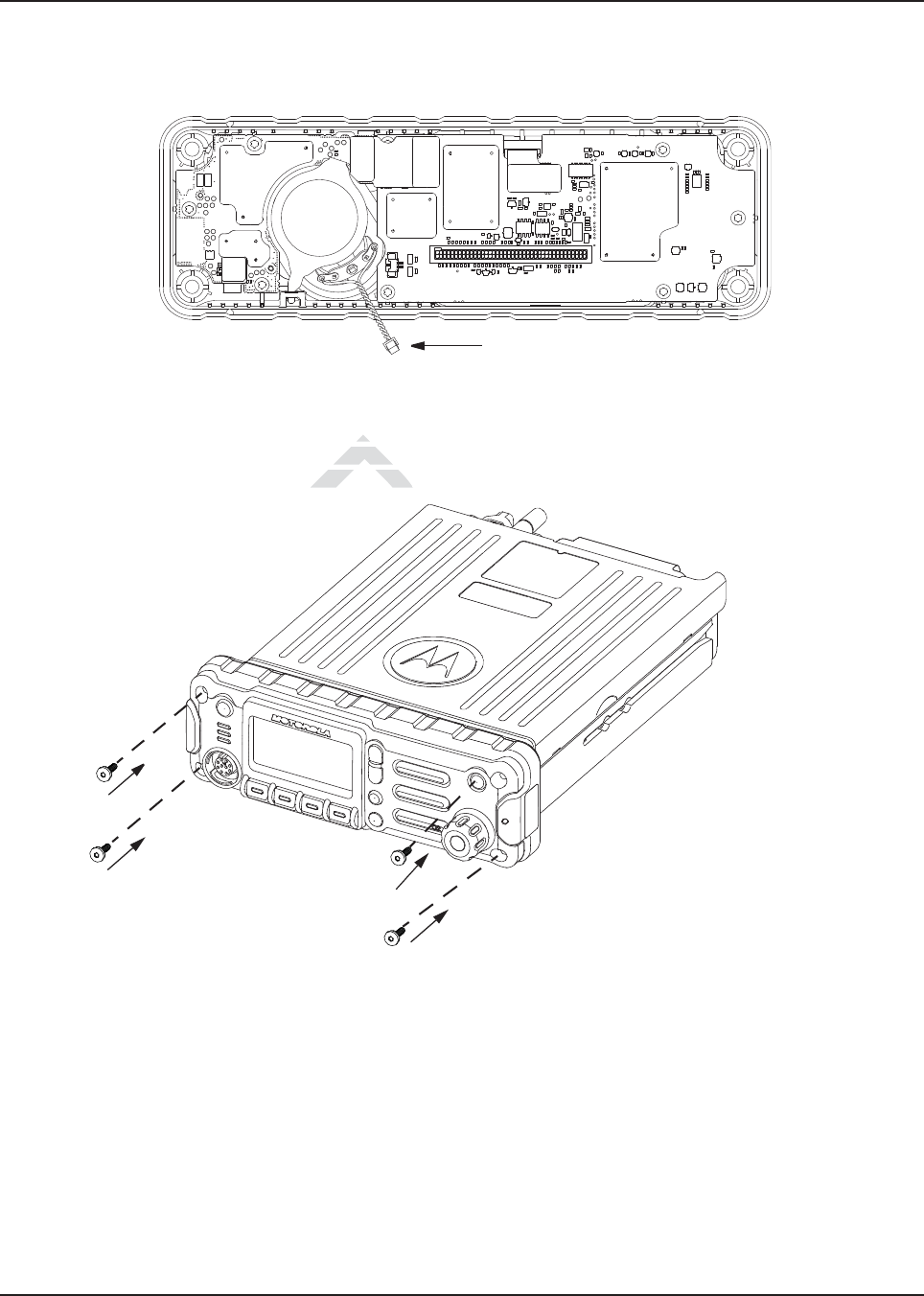
MN003109A01_aa
Standard Configurations Speaker 2-37
4. Put the control head face down on a clean, flat surface to avoid damaging it. Do not touch the
o-ring on the back housing.
5. Carefully disconnect the speaker connector from the circuit board as shown in Figure 2-42.
Figure 2-42. Disconnecting the Speaker Connector
6. Reattach the front housing assembly to the back housing assembly as shown in Figure 2-43.
Make sure that the flex is returned to its original position and that the o-ring on the back
housing assembly is not pinched.
Figure 2-43. Reattaching the Control Head
7. Secure the front housing assembly back to the back housing assembly with four new screws
using the Torx T-20 bit as shown in Figure 2-43. Apply 9 in. lbs. torque for each screw.
D
g a
g a
is returnis retur
not pinched.not pinched
aft
Draft
raft
Draf
Dr
Dra
Dra
Dra
Dra
Dra
Dra
Dra
Draf
r
r
ra
ra
ra
ra
ra
ft
ft
ft
ft
ft
ft
ra
ra
ra
a
raft
af
af
af
af
af
ft
ft
af
af
f
af
ft
ft
af
ft
a
ft
ft
af
ft
af
a
ft
af
a
af
ft
af
ft
a
aft
aft
af
ft
a
f
ft
ft
ft
ft
ft
f
a
a
f
f
a
f
a
a
a
f
f
a
f
a
a
a
raft
a
aft
a
aft
af
af
aft
a
af
ft
ft
ra
a
ft
a
ra
ft
ft
ft
f
f
ft
f
aft
f
aft
f
aft
ft
ft
f
ft
ft
f
ft
t
ft
t
t
t
ft
ft
ft
ft
ft
ft
ft
ft
ft
ft
t
ft
ft
ft
ft
ft
t
aft
ft
ft
ft
t
ft
ft
aft
t
ft
ft
t
ft
ft
ft
t
ft
t
t
ft
ra
ft
ft
t
ft
ft
ft
ft
t
ft
ft
a
t
t
t
t
t
t
D
a
ft
ft
r
ra
ra
r
a
f
f
f
f
f
f
f
f
f
af
a
af
a
af
f
ft
ft
ft
ft
f
f
f
f
f
t
t
t
ft
ft
ft
ft
ft
ft
ft
ft
ft
f
t
ft
ft
ft
t
t
t
ft
ft
ft
t
t
t
t
t
t
ft
ft
ft
ft
ft
ft
a
a
a
D
ra
ft
ft
ft
ft
ft
ft
ft
t
ft
t
t
ft
ft
t
t
t
ft
ft
t
t
t
t
ft
ft
ft
ft
ft
ft
t
D
ft
ft
ra
ra
ra
r
r
ra
ra
ra
a
ra
ra
a
ra
af
ft
ft
af
raf
ra
ra
r
a
a
a
raf
af
raf
a
a
a
ra
a
t
D
aft
raft
ft
ft
ft
ft
f
f
af
af
a
a
t
t
t
t
t
ft
ft
f
ft
f
f
af
af
a
a
a
a
af
f
f
f
f
f
f
ft
t
ft
ft
t
t
t
a
af
ft
ft
ft
ft
ft
ft
ft
f
t
ft
ft
a
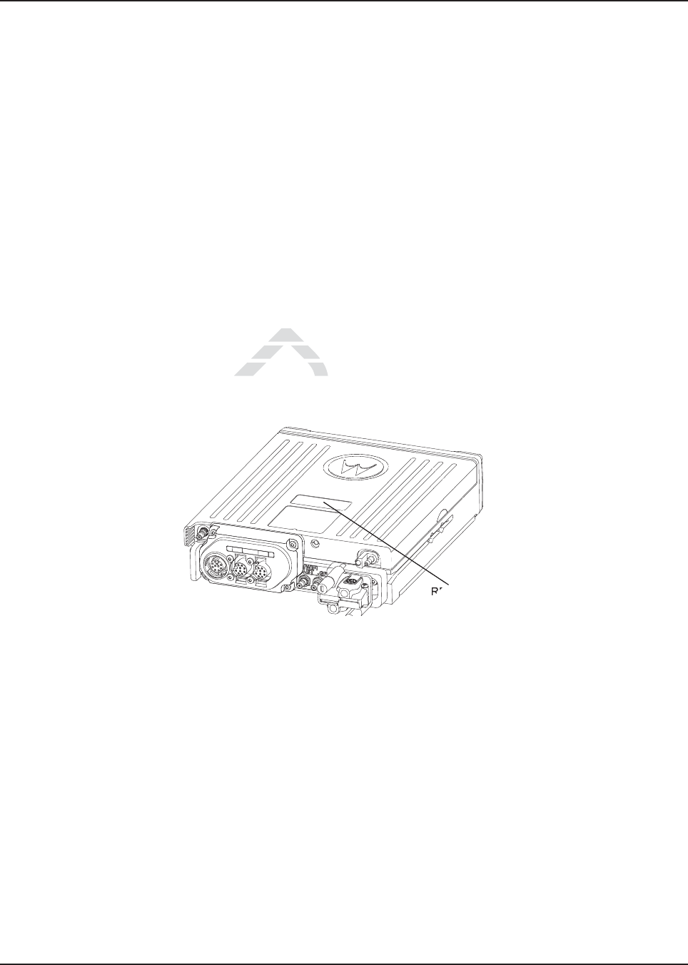
MN003109A01_aa
2-38 Standard Configurations Microphone Hang-Up Clip
2.6 Microphone Hang-Up Clip
2.6.1 Standard or O3 Control Head Hang-Up Clip
The hang-up clip must be within reach of the operator(s) and close enough to the control head to
prevent cable strain. Measure this distance before actually mounting the bracket. Since the bracket
has a positive-detent action, the microphone can be mounted in any position.
Use the hang-up clip as a template to locate the mounting holes. To avoid interference when
removing the microphone, install the flathead screw in the top clip hole.
Some microphone models require the grounding of the microphone clip in order for HUB operation to
work correctly. Refer to the documentation that comes with your Motorola microphone model.
NOTE: For multi-control head configuration where only one of the control heads has a microphone,
the control heads without a microphone attached must have their HUB or Monitor pin
(J100-22) jumpered by a wire to GND (J100-1 or J100-14) for HUB operation to work.
2.7 RFID (Option)
An APX mobile radio equipped with an RFID tag allows an alternate option for tracking the radio
asset. Each RFID equipped radio has an RFID tag preprogrammed with the individual radio’s serial
number (also found on the FCC label) as well as band and radio model information (see below for
further information).
Figure 2-44. RFID Location on Mid Power Radio
RFID Tag
Draft
th an Rth an R
dio has an Rdio has an R
CC label) as wellCC label) as we
raft
raft
Draft
Draf
Dra
D
D
D
D
D
D
Dr
Dr
D
Dr
Dr
Dr
Dra
Dra
Dra
ra
ra
f
f
f
f
ra
a
a
f
f
f
af
Dr
ra
ra
raft
raft
ft
ft
a
a
ft
ft
ft
f
raft
raft
raft
aft
ft
a
a
a
ft
ft
f
ft
Dr
f
f
f
aft
aft
f
ft
ft
f
f
ft
f
f
f
ft
aft
ft
ft
aft
aft
ft
ft
aft
ft
ft
ft
ra
a
ra
a
ra
ft
ft
ft
ft
ft
aft
ft
ft
ft
ft
aft
aft
aft
t
t
f
f
D
Dr
Dra
Dra
Dr
Dr
Dr
Dr
Dr
Dr
Dr
Dr
Dr
ft
ft
ft
ft
ft
ft
ft
ft
ft
ft
D
Dr
D
Dr
t
t
Dr
Dr
Dra
Dr
ra
ra
ft
f
f
ft
ft
ft
ft
ft
ft
ft
ft
ft
ft
ft
f
f
ft
ft
ft
t
t
t
t
Dr
D
D
Dr
ra
a
a
ra
a
a
a
a
a
ra
ra
ra
ra
ra
f
f
f
Dr
Dr
Dr
t
t
ft
f
f
f
ft
ft
ft
ft
a
a
ra
ra
ra
ra
ra
ra
a
a
f
ft
ra
ra
ra
af
a
a
Dra
Dra
f
ra
raf
D
ra
ra
ra
a
ft
ra
ra
ra
ra
ra
ra
ra
ra
ra
ra
ra
ra
a
Dr
Dr
Dra
Dra
a
a
a
af
ra
ra
ra
ft
ft
ft
ft
ft
ft
ft
ft
ft
ft
ft
ft
f
ft
ft
ft
ft
D
ft
ft
ft
ft
ft
f
f
ft
ft
ft
ft
ft
ft
ft
ft
ft
ft
ft
ft
ft
ft
ft
ft
ft
t
t
t
ft
f
f
f
f
f
D
t
Dra
t
t
D
D
D
D
D
D
a
a
a
a
a
af
af
af
aft
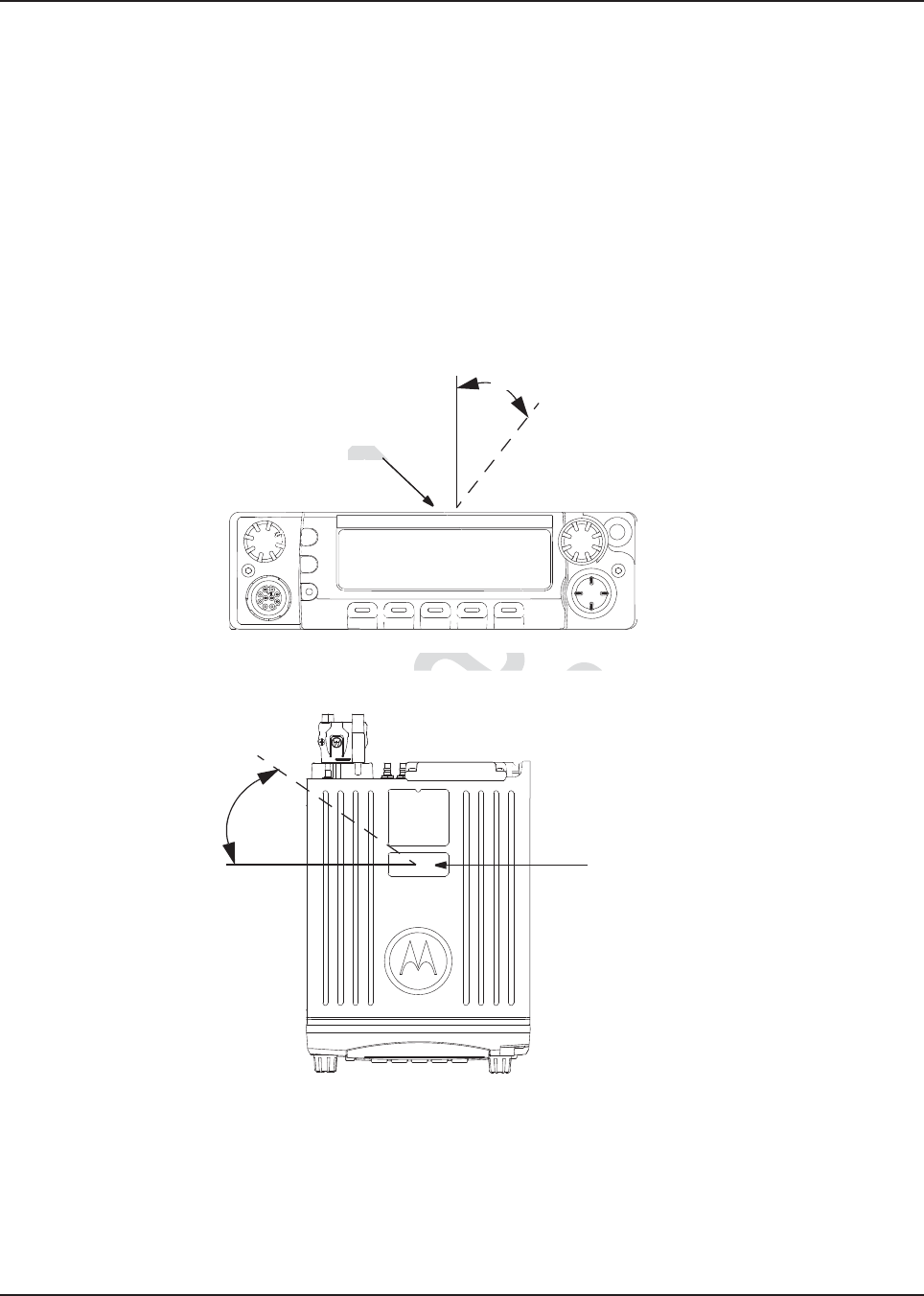
MN003109A01_aa
Standard Configurations RFID (Option) 2-39
2.7.1 RFID Reading
To read an RFID tag using a UHF Gen 2 RFID reader (e.g. Motorola’s MC9090-G), open an
appropriate RFID read application, point the RFID reader at the tag and activate the reader's RFID
antenna (e.g. pull Motorola’s MC9090-G scanning trigger). RFID reader must be within 1 foot from
tag in order to read.
Two variables, Read Angle and Reader Orientation, aid in the distance needed to read and write to
the RFID Tag. Read distance is independent of Tag Angle, but the reader should be as close to
perpendicular to the tag as possible (Read Angle).
As Read Angle increases past 60 degrees, read distance will begin to decrease; tag will become
unreadable once Read Angle exceeds 90 degrees (see Figure 2-45). RFID tag cannot be read
through metal. The orientation of the reader (Reader Orientation) and the tag must be aligned to
improve read and writability (see Figure 2-47).
Figure 2-45. Read Angle for Mid Power Radio
.
Figure 2-46. Tag Angle for Mid Power Radio
Read Angle
RFID Tag
RFID Tag
Tag Angle
Draft
Read Angle for Mid Power d Angle for Mid Power
Dra
Dra
D
D
D
D
D
D
D
D
D
D
D
D
D
D
D
D
D
D
ra
r
ra
ra
ra
ra
ra
a
a
a
r
Dr
Dr
Dr
Dra
Dr
D
D
D
D
D
D
D
D
D
D
D
D
D
D
D
D
D
D
D
D
D
D
D
Dr
Dr
r
D
D
D
D
D
D
D
D
D
D
D
D
D
D
D
D
D
D
D
D
D
D
D
D
D
D
D
D
D
D
D
D
D
D
D
D
D
D
D
D
D
D
D
D
D
Dr
D
D
D
D
D
D
D
D
D
D
D
D
D
D
D
D
D
D
D
D
D
D
D
D
D
D
D
D
D
D
D
D
D
D
D
D
D
D
D
D
D
D
D
D
D
D
D
D
D
D
D
D
D
D
D
D
D
D
D
D
D
r
Dr
r
D
Dr
D
D
D
D
D
D
ra
Dra
Dra
Dra
r
Dr
Dra
Dra
ra
ra
Dra
ra
r
r
Dra
Dr
Dr
ra
Dra
Dra
Dra
ra
Dra
Dra
Dra
ra
ra
ra
ra
ra
ra
Dra
Dra
Dra
ra
ra
ra
ra
ra
ra
a
a
a
a
a
a
ra
ra
a
ra
ra
a
a
a
a
a
a
a
a
a
a
a
a
a
a
a
a
a
D
D
D
D
RFID TRFID T
aft
ft
ft
ft
ft
f
ft
ft
ft
ft
ft
f
f
f
f
ft
ft
ft
f
f
ft
f
ft
f
f
ft
ft
ft
ft
ft
ft
ft
ft
ft
ft
ft
f
ft
ft
ft
ft
ft
ft
ft
ft
f
f
f
f
f
f
f
f
f
f
f
f
f
f
f
f
f
f
f
f
f
f
f
f
f
f
f
f
f
f
f
f
f
f
f
ft
f
f
f
f
f
ft
f
f
f
f
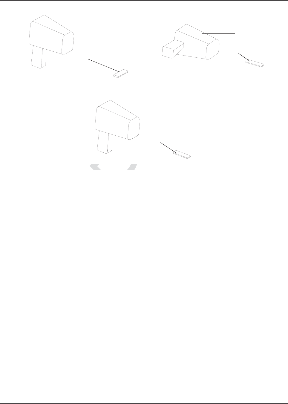
MN003109A01_aa
2-40 Standard Configurations RFID (Option)
Figure 2-47. Examples of Reader and Tag Aligned (Reader Orientation)
Figure 2-48. Example of Reader and Tag Misaligned (Reader Orientation)
Reader
Tag
Reader
Tag
Reader
Tag
Draft
ample of Reader and Tag
ample of Reader an
D
D
D
D
D
D
D
D
D
MN003109A01_aa
Standard Configurations RFID (Option) 2-41
2.7.2 Programming RFID (If Equipped)
The user can reprogram the tag (up to 12 ASCII characters when encoded to hexadecimal format)
using any UHF Gen 2 capable RFID writer (e.g. Motorola’s MC9090-G).
NOTE: Follow read direction in Section 2.7.1 to optimized reprogramming.
Table 2-1. Model Number Chart in 12-Digit ASCII Format
Model Number Radio Tier/Band/Output Level Last Two Digits
M37TSS9PW1AN APX Mobile 700/800 VHF UHF–MP T0
M30KSS9PW1AN APX Mobile SB–MP VHF D2
M24KSS9PW1AN
APX Low Tier Mobile–MP VHF D8
M22KSS9PW1AN
M36KSS9PW1AN APX Lowest Tier Mobile–MP VHF D9
M30KTS9PW1AN APX Mobile SB–HP VHF D3
M30QSS9PW1AN APX Mobile SB–MP UHF1 E2
M30QTS9PW1AN APX Mobile SB–HP UHF1 E3
M30SSS9PW1AN APX Mobile SB–MP UHF2 D2
M20TSS9PW1AN APX Mobile DB–MP 700/800–MP VHF R2
M30TXS9PW1AN APX Mobile DB–MP 700/800–HP VHF R3
M30URS0PW1AN APX Mobile SB–MP 700/800 F2
M22URS9PW1AN
APX Low Tier Mobile–MP 700/800 F8
M24URS9PW1AN
M36URS9PW1AN APX Lowest Tier Mobile–MP 700/800 F9
M24QSS9PW1AN
APX Low Tier Mobile–MP UHF1 E8
M22QSS9PW1AN
M36QSS9PW1AN APX Lowest Tier Mobile–MP UHF1 E9
M24SSS9PW1AN
APX Low Tier Mobile–MP UHF2 E8
M22SSS9PW1AN
M36SSS9PW1AN APX Lowest Tier Mobile–MP UHF2 E9
M22WRS9PW1AN APX Low Tier Mobile–MP 900 F8
Table 2-2. Serial Number with Radio Band/Tier/Power
Characters Radio Band/Tier/Power
F 700/800 and 900
DVHF
ft
P 700/800700/8
aft
e–MP 700/800e–MP 700/8
t
t
raft
SB–MP 700/800B–MP 700/800
t
raf
bile DBbile
–MP 700/800–HP VHMP 700/800–
Dra
X Mobile DBe DB
–MP 700/800–M–MP 70
Dr
APX Mobile SB–MP UHF2APX Mobile SB–MP
D
D
APX Mobile SB–HP U
APX Mobile SB–
D
D
APX Mobile SB–MAPX Mobile SB–
D
D
Mobile Mobile
D
D
D
D
D
Dr
ra
raf
aft
ft
t

MN003109A01_aa
2-42 Standard Configurations Completing the Installation
2.8 Completing the Installation
Complete the installation by connecting the speaker to the accessory cable; verify the ignition sense
wire is attached according to planned ignition sense; verify the control head is attached to either the
TIB or the CAN extension cable; and then attach the power cable to the back of the transceiver.
E UHF
R 700/800 and VHF
T Multi-Band
E UHF1 and UHF2
S 700/800 and UHF
0 APX 8500
1 APX 7000
2 APX 7500 Mid Power
3 APX 7500 High Power
4 APX 6000
5 APX 6500 Mid Power
6 APX 6500 High Power
7 APX Low Tier Portable
8 APX Low Tier Mobile MP/APX 4500 MP/APX 2500 MP
9 APX Lowest Tier Mobile MP/APX 1500 MP
Table 2-2. Serial Number with Radio Band/Tier/Power
Draft
tionon
the speaker to the accessoe speaker to the accesso
on sense;on sense;
verify the contro
verify the contr
ach the power cable to th
ch the power cable to
Dra
APX Lowest Tier Mobile MP/APX Lowest Tier Mobi
Dr
APX Low Tier Mobile MPAPX Low Tier M
D
D
APX Low Tier PortaAPX Low Tier Po
D
D
PX 6500 HighPX 6500 High
D
500
500
D
D
D
Dr
Dra
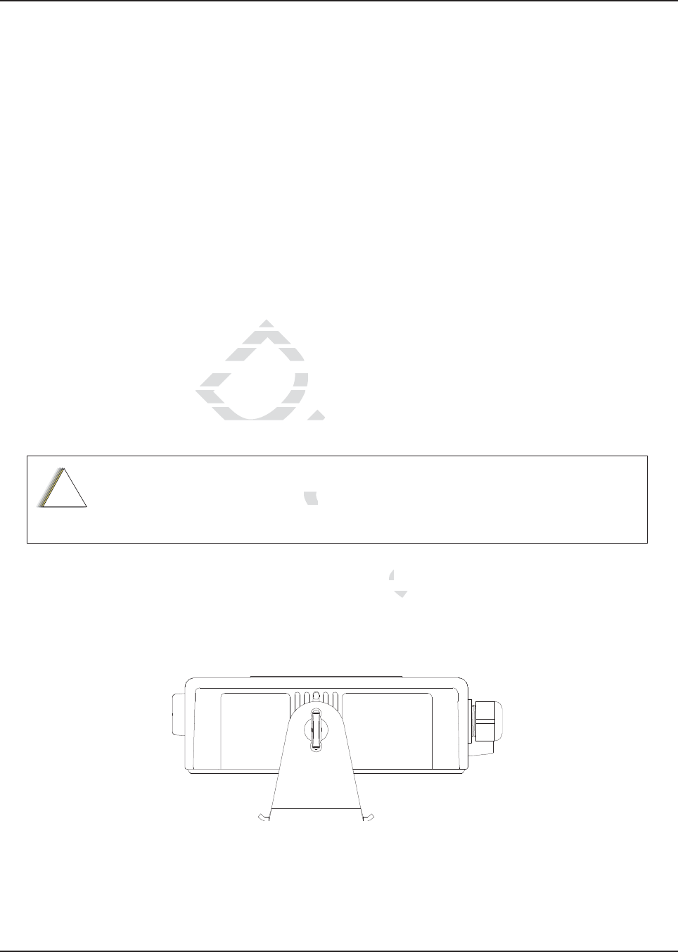
Chapter 3 Universal Relay Controller Installation
The Universal Relay Controller (URC) is an extension of and an orderable accessory for O7 or O9
control head. URC is used to control high power switching peripherals, e.g. lightbar. URC works on
all lightbars which can be controlled by power application. URC is connected to the transceiver's
MMP port.
The URC design consists of a microcontroller and uses 10 relays to control the switching device. A
separate ground for isolation exists between the relay and MCU sections, which is provided by the
use of iCoupler from Analog Devices. Each relay is connected to an output with 15 A fuse. The
maximum load allowed on each output is 12 A. Two cables, each with the maximum of 60 A, can be
used to connect to the input connector at the bus bar. Each cable is connected with a 60 A circuit
breaker. One-wire EEPROM is employed to enable MMP to recognize the URC accessory ID. CPS
can be used to program the relay patterns.
When installing URC, make sure to plan the installation carefully and leave additional room in the
front and rear of the box for cabling and accessory connections; and also to the sides of the radio so
that you may access and install the trunnion screws.
The recommended mounting location for URC is in the car trunk, either next to the transceiver or
within the area not further than 4.5 m away from the transceiver. Ensure that sufficient cooling is
provided. Do not cover URC with baggage, blankets, etc.
3.1 Universal Relay Controller Mounting
The mounting location must be accessible and visible. Select a location that permits routing the
cable as directly as possible.
NOTE: For optimum URC performance, orient the mounting trunnion as shown in Figure 3-1.
Figure 3-1. Universal Relay Controller Orientation
An adjustable trunnion, which allows a number of mounting positions, is supplied for mounting the
URC. The installation must not interfere with the operation of the vehicle or its accessories.
Do not backfeed power into URC.
!
C a u t i o n
ft
tingg
Se
Se
Draft
to
to
abling andabling an
stall the trunnstall the trunn
unting location for URCunting location for
her than 4.5 m away from
her than 4.5 m aw
RC with baggage, blanketRC with baggage,
RC.RC.
ra
ft
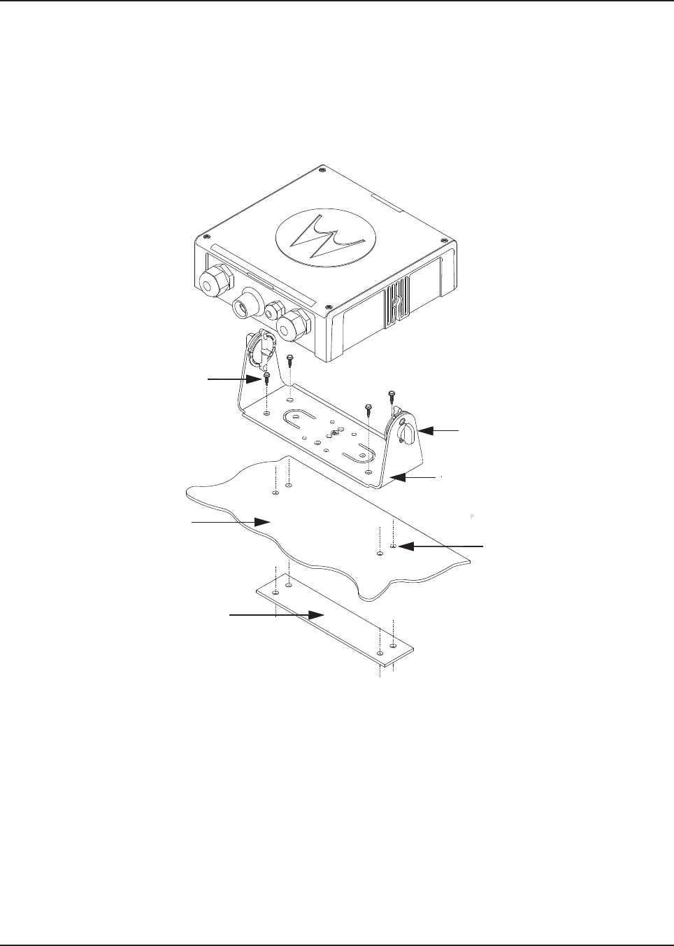
MN003109A01_aa
3-2 Universal Relay Controller Installation Universal Relay Controller Mounting
Install the URC as follows:
1. Use the URC trunnion as a template to mark the mounting holes;
drill 5/32" holes. If mounting on a plastic surface, use a metal backing plate.
2. Attach the trunnion bracket using all four 10 – 16" x 5/8" self-tapping screws provided.
3. Temporarily install the URC (adjust for proper viewing angle) and fasten it to the trunnion with
two wing screws. Test the installation to ensure that the unit is securely locked in place.
Figure 3-2. Universal Relay Controller Installation Exploded View
Adjust the universal relay controller
to desired angle and secure with
wing screws
Use four mounting screws on all
installations
TRUNNION
Drill four 5/32” holes in
mounting surface
Mounting surface
IMPORTANT:
Use a metal backing plate (not
supplied) if mounting trunnion on
plastic or unstable surface
Draft
Dra
D
D
a
t
t
t
t
D
D
D
D
D
D
D
D
D
D
D
D
D
D
D
D
D
D
D
D
D
D
D
D
D
D
D
D
D
D
D
D
D
D
D
D
D
D
D
D
D
D
D
D
D
D
D
D
D
D
D
D
D
D
D
D
D
D
D
D
D
D
D
D
D
D
D
D
D
D
D
D
D
D
D
D
D
D
D
D
D
D
D
D
D
D
D
D
D
D
D
D
D
D
D
D
D
D
D
D
D
D
D
D
D
D
D
D
D
D
D
D
D
D
D
D
D
D
D
D
D
D
D
D
D
D
D
D
D
D
D
D
D
D
D
D
D
D
D
D
D
D
D
D
D
D
D
D
D
D
D
D
D
D
D
D
D
D
D
D
D
D
af
af
af
af
raft
D
D
D
D
D
D
D
D
D
D
Dr
D
D
Dr
Dr
Dr
D
D
Dr
Dr
D
Dr
D
D
D
D
D
Dr
Dr
Dra
Dr
Dr
a
r
Dr
D
ra
D
Draf
af
D
Dr
ra
ra
Dr
Dr
Dr
Dr
ra
Dr
D
D
D
D
D
D
D
D
D
D
D
D
D
D
Dr
D
D
D
D
D
D
Dr
Dr
Dr
Dra
Dra
Dr
Dr
a
Dr
D
a
Dr
Dr
a
Dr
Dr
a
Dr
Dr
ra
Dr
Dr
a
D
D
D
D
D
D
D
D
a
a
D
D
D
D
D
Dr
ra
Dr
D
Dr
Dr
D
D
D
Dr
Dr
Dr
D
D
D
D
D
Dr
ra
Dr
ra
Dr
ra
Dra
Dra
Dr
r
Dr
Dr
Dr
Dr
Dr
Dr
Dr
Dr
Dr
Dr
Dr
Dr
Dr
Dr
Dr
Dr
r
Dr
Dr
Dra
Dr
Dra
Dr
Dr
Dr
Dr
Dr
Dr
Dr
Dr
D
D
D
D
D
D
D
D
D
D
D
a
D
D
D
D
D
D
D
D
D
D
a
D
D
D
D
D
D
D
Dra
D
Dr
a
D
D
D
D
D
D
D
D
D
a
a
D
D
a
Dr
f
a
r
r
ra
ra
a
af
r
Dra
r
r
ra
r
D
D
D
D
D
D
D
D
D
D
D
D
D
D
D
D
D
D
D
D
D
D
D
D
D
D
D
D
D
D
D
D
D
D
D
D
D
D
D
D
D
D
D
D
D
D
D
D
a
a
a
a
ra
ra
f
f
af
af
a
a
a
a
a
a
a
ra
af
a
D
D
D
D
D
D
D
D
D
a
a
a
a
ft
ft
a
af
af
af
D
D
D
D
D
D
D
D
D
a
ft
f
ft
f
ft
f
t
D
D
D
D
D
af
af
af
af
af
Draf
D
Dr
D
D
D
af
D
Dr
Dr
a
a
Dra
Dra
Dr
Dra
Dra
Dr
Dr
r
ra
a
a
af
a
D
a
a
a
af
af
af
af
D
D
a
a
a
D
D
D
D
D
D
D
D
D
D
D
D
D
D
D
D
D
D
D
D
D
D
D
D
D
D
D
D
D
D
D
D
D
D
D
D
D
D
D
D
D
D
D
D
D
D
D
D
D
D
D
D
D
D
D
D
D
D
D
D
D
D
D
D
D
D
D
D
D
D
D
D
D
D
D
D
D
D
D
D
D
D
D
D
D
D
D
D
D
D
D
D
D
D
D
D
D
D
D
D
D
D
D
D
D
D
D
D
D
D
D
D
D
D
D
D
D
D
D
D
D
D
D
a
a
a
a
a
a
a
a
a
a
a
a
a
a
a
a
a
a
a
a
af
af
a
D
D
D
D
D
D
D
D
D
D
D
D
D
D
D
r
r
r
r
r
r
af
af
af
af
af
af
f
f
f
f
f
f
f
f
f
aft
aft
aft
aft
aft
aft
aft
aft
aft
ft
ft
aft
ft
ft
ft
D
D
D
D
af
af
af
af
ft
ft
ft
ft
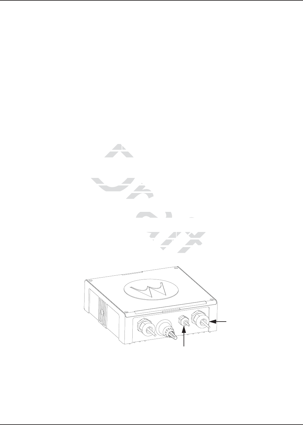
MN003109A01_aa
Universal Relay Controller Installation O7/O9 Universal Relay Controller Cable Assembly 3-3
3.2 O7/O9 Universal Relay Controller Cable Assembly
3.2.1 Power Cable
1. Remove the cap nut of power cable gland assembly, and insert the power cable through the
cap nut and neoprene seal in the cable gland body. Use power cable with either AWG 6 or
AWG 8 only (recommended OD range of cable is 5.5 mm to 9 mm) that is able to withstand
80 A and 50 A respectively, to ensure water sealing of the controller. User can decide to
install one or two power cables based on the requirements. The power cables (A+) are not
supplied.
2. The loose end of the power cable with cable strip length 7.94 mm (5/16”) is then placed on
the power lug and secured down by a set screw. The cap nut is then reassembled with
tightening torque 18 lb-in.
3. The other end of the power cable should be connected to circuit breaker (Motorola part
number 40012006001) end which indicates "AUX" and then, to power supply on the other
end which indicates "BAT", instead of connecting to power supply directly.
4. Repeat steps 1 to 3 to install the second power cable, if required.
5. If only one power cable is installed, it is recommended to cover the other side of the power
cable gland with power cable gland seal with tightening torque 18 lb-in.
3.2.2 Ground Cable
1. Remove the cap nut of ground cable gland assembly, insert the ground cable through the cap
nut and then reassemble the cap nut. Use ground cable with AWG 14 only (recommended
OD range of cable is 2 mm to 4 mm) that is able to withstand 5 A. The ground cables (A+) are
not supplied.
NOTE: The ground is used to switch the relays, and not act as a ground to the actual device being
controlled.
2. The loose end of the ground cable with cable strip length 7.94 mm (5/16”) is then connected
to a two-pin terminal block. Both pins on the terminal block are inter-connected and either pin
can be used. The cap nut is then reassembled with tightening torque 7 lb-in.
Figure 3-3. Power and Ground Cable Glands
Ground Cable Gland
Power Cable Gland
Draft
is inis in
stast
er cable glaer cable gla
nut of ground cable glandnut of ground cable
emble the cap nut. Use groemble the cap nut. U
2 mm to 4 mm) that is able4 mm) tha
h the relays, and not act ae relays, and not act a
with cable stith cable st
rip length 7.9
rip length 7
n the ten the te
rminal block
rminal bloc
mbled with tightmbled with ti
t
t
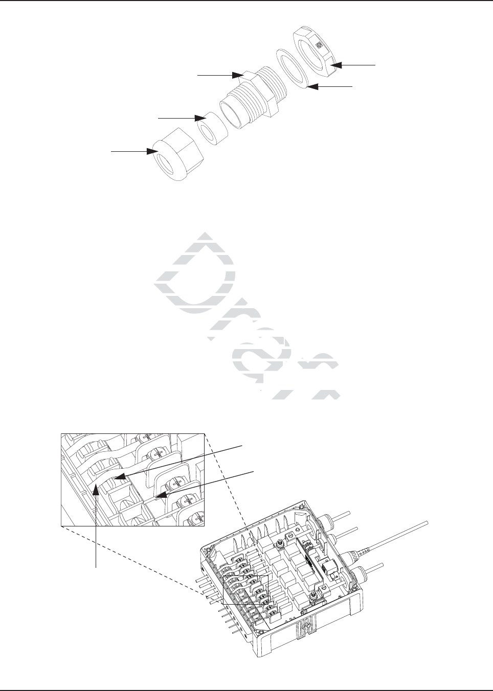
MN003109A01_aa
3-4 Universal Relay Controller Installation O7/O9 Universal Relay Controller Cable Assembly
Figure 3-4. Cable Gland Assembly with Gasket
3.2.3 Wires
1. Assemble the wires into the lightbar gasket retainer and lightbar gasket. The URC can
support lightbars through control wires with outer diameter ranging from
1.52 mm to 3.77 mm (0.06” to 0.148”), with wire gages ranging from AWG 12 – 20.
2. Each individual loose wire (prior to stripping off the wire jacket) needs to be inserted one at a
time through the chassis. Ensure the lightbar wire is straight before inserting the wire into the
chassis. Each wire is sealed individually by the radial gasket seal. When a thick wire (i.e.
AWG 14 wire or wire OD > 2.90 mm) is inserted through the chassis, there is potential torn at
the rubber gasket. Remove the rubber gasket residual and continue to the next step.
3. Thin wires 2.5 mm and below should be dressed into the retention feature using a black stick
(see Figure 3-5); thick wires above 2.5 mm should be routed above the retention feature.
Strip off the wire until 7.94 mm (5/16”) after the wire is inserted into the URC, and install the
wire into respective lightbar terminal block.
4. Cover the lightbar gasket retainer's hole with seal, gasket and ground cable gland, if no wire
is inserted.
Figure 3-5. Wires Installation
Counter Nut
Gasket, Cable Gland
Neoprene Seal
Cap Nut
Cable Gland Body
WIRE RETENTION FEATURE
LIGHTBAR WIRE WITH DIAMETER
2.5 mm AND BELOW
LIGHTBAR WIRE
WITH DIAMETER
ABOVE 2.5 mm
Draft
ligh
ligh
control w control w
0.06” to 0.148”)0.06” to 0.148
ose wire (prior to strippiose wire (prior to st
chassis. Ensure the lightba
hassis. Ensure the
s sealed individually by ths sealed individually
e
D > 2.90 mm) is inserted thD > 2.90 mm) is ins
ve the rubber gasket residue rubber gaske
should be dresseshould be dresse
d into thed
ove 2.5 mm should be route2.5 mm should be route
6”) after the 6”) after the
wire is insertewire is inser
block.block.
with seal, gasket anwith seal, gasket an
d
t
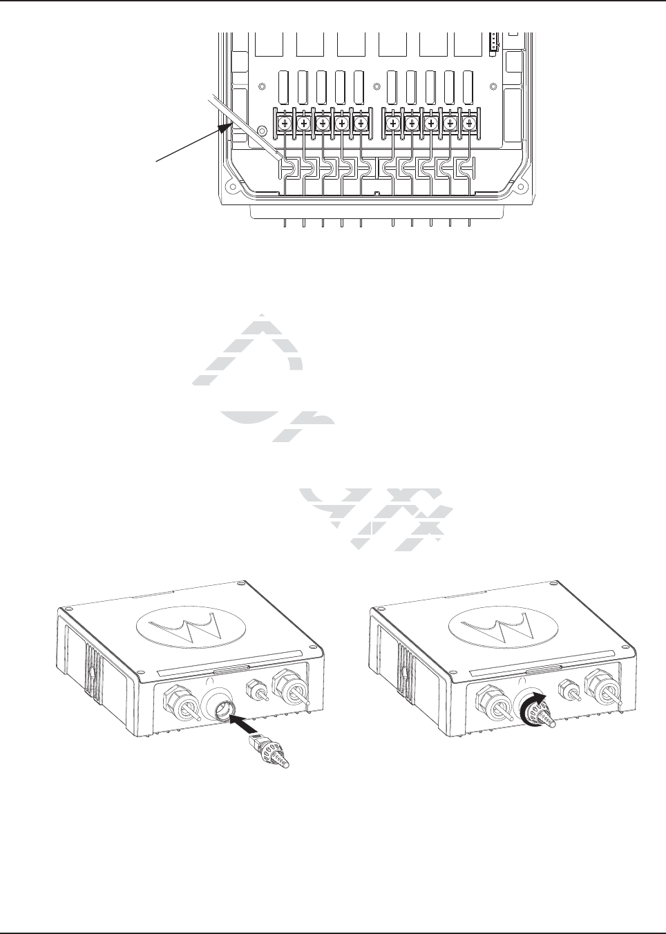
MN003109A01_aa
Universal Relay Controller Installation O7/O9 Universal Relay Controller Cable Assembly 3-5
Figure 3-6. Wire Installation with Black Stick
5. The lightbar gasket should be replaced at each reassembly of the wire.
NOTE: Use of other cable gages except as recommended in this manual may result in water
intrusion. Any reassembly of wire needs a new lightbar gasket replaced. If the current loading
for one wire is higher than 12 A, the wires should be splitted before being assembled to the
URC system. Wires kit (PMKN4109_) is provided to ease installation of the URC. Incorrect
use of the wires kit, e.g. improper connection at external loose end wires, may impact the
robustness of the URC.
Remove the wires and gasket residual inside the URC after the wire installation, before
closing the top housing of the URC.
3.2.4 O7/O9 to URC Cable
The O7/O9 to URC cable (Motorola part number 3064153H02) can be assembled either before or
after reassembling the top housing. Assemble the RJ45 port of the cable into the RJ45 connector on
the URC and turn the locking collar instead of cable, 90 degrees to the right to ensure it is locked
properly. After that, test whether the cable is locked properly or not by trying to pull out the cable.
Figure 3-7. O7/O9 to URC Cable Installation
Black Stick
Draft
y o
y o
han 12 Ahan 12
s kit (PMKN41s kit (PMKN4
kit, e.g. imprkit, e.
oper coper
the URC.
the U
and gasket residual insideand gasket residual
ng of the URC.he UR
t number 3064153H02) canumber 3064153H02) c
mble the RJ45 port of the c
mble the RJ45 port of the
f cable,f cable,
90 degrees to
90 degrees
ked properly or nked properly or n
t

MN003109A01_aa
Notes
3-6 Universal Relay Controller Installation
Draft
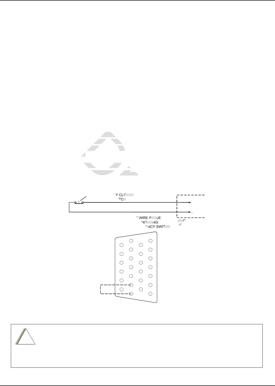
Chapter 4 Options and Accessories Installation
4.1 Dash-Mount Accessory Installation
For dash-mounted configurations, the accessories must be installed through the accessory
connector assembly that is located on the rear of the radio, adjacent to the power connector.
Motorola-approved accessories are supplied with male terminals crimped to a 20-gauge wire
specifically designed to fit the plug of the accessory connector assembly.
Insert the male terminal into the accessory connector assembly in the appropriate location and
connect the accessory connector assembly in the rear accessory port. Do not use other generic
terminals in the plug. Generic terminals can cause electrical intermittencies and may cause damage
to the plug.
4.1.1 Dash-Mount Emergency Pushbutton or Footswitch Installation
Mount the footswitch using the hardware that comes with the kit. Open the accessory cable
connector housing; remove the jumper wire. Connect the emergency switch wires to pins 14 and 15
(see Figure 4-1). Close the connector housing; route the finished cable from the switch location to
the control head location.
NOTE: The emergency footswitch should be attached with A+ unattached.
A+ should be attached after successfully securing the screws in the connector.
Figure 4-1. Emergency Switch Wiring Diagram
The radio is sold with correct accessory cables and jumpers in order to have emergency
de-activated by default, regardless of the setting in CPS. However, if cables are not used, or if
jumpers are removed without replacing with an emergency accessory button/switch at one of
the accessory ports, the radio will power-up upon the application of A+. The display may not
show an indication that the radio is on, and this can result in an incorrect operation of the radio
as well as excessive current drain of the vehicle’s battery when the engine is off.
ACCESSORIES
CONNECTOR
J2 IN DASH MOUNT
J100 IN REMOTE MOUNT
PIN 14
PIN 15
NOTE 1
SPST NORMALLY CLOSED
EMERGENCY SWITCH
NOTE 1: REMOVE BLACK JUMPER WIRE INSIDE
ACCESSORY CONNECTOR HOUSING.
INSERT WIRES FROM EMERGENCY SWITCH
GND
EMER
1
7
8
14
13
20
21
26
!
C a u t i o n
Dra
hardwahardw
the jumper wthe jumper w
e connector house connector ho
on.on.
footswitch should be attacfootswitch should b
hed after successfully hed after successfu
sec
raft
ft
t
ACC
C
af
aft
OSED
CH
R WIRE INSIDE
OUSIN
ENCY SWITCH
ft
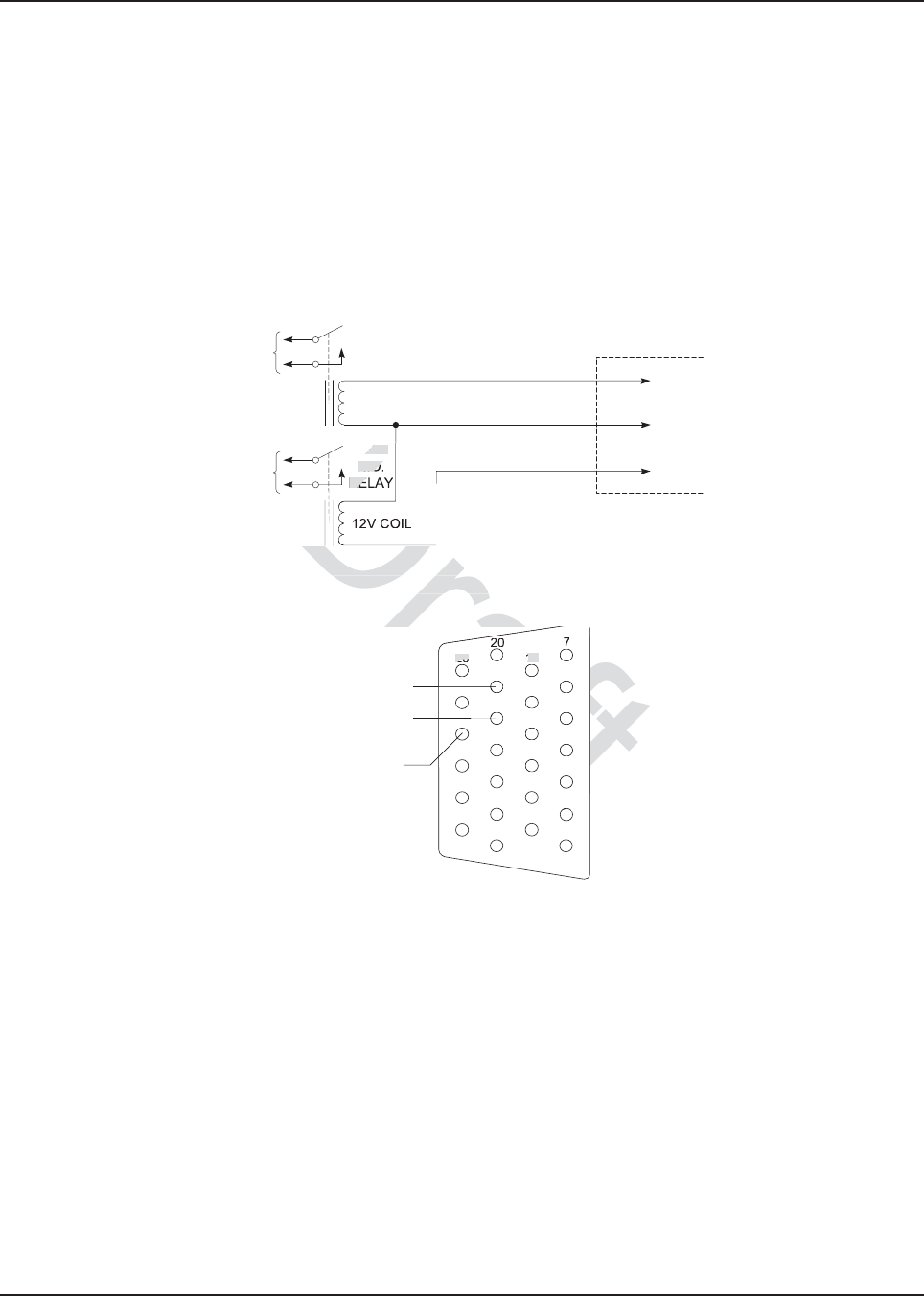
MN003109A01_aa
4-2 Options and Accessories Installation Remote-Mount Accessory Installation
4.1.2 Dash-Mount Horn and Lights (External Alarms) Relays
NOTE: For installations that use the horn/lights option, select a suitable location for mounting
(normally under the dash) and, referring to Figure 4-2, perform the following procedure:
1. Horn Relay – Connect the relay contacts across the horn ring switch, typically found in the
steering column. Open the accessory cable connector and connect the two control wires
(male pins) into locations 18 and 24 of the connector.
2. Lights Relay – Connect the relay across the head lamp ON/OFF switch, typically found in
the steering column. Open the accessory cable connector and connect the two control wires
(male pins) into locations 19 and 24 of the accessory connector.
Figure 4-2. Horn/Light Wiring Diagram
Figure 4-3. Radio MAP Connector
4.2 Remote-Mount Accessory Installation
Perform the following installation procedure:
1. Select an appropriate place to mount the option or accessory hardware.
2. Route the accessory-to-control head cables under floor coverings or behind panels so that
the vehicle occupants do not snag or break the wires.
3. Attach wires from the accessory to the appropriate wire on the VIP cable (see Table 4-1 and
Table 4-2).
CONNECT
ACROSS HORN
RING SWITCH
CONNECT
ACROSS HEAD
LAMP SWITCH
SPST
N.O.
RELAY
12V COIL
12V COIL
VIP OUT 1
SWB+
VIP OUT 2
SPST
N.O.
RELAY
ACCESSORIES
CONNECTOR
PIN 18
PIN 24
PIN 19
SWB+
VIP OUT 2
(LIGHTS)
VIP OUT 1
(HORN)
1
7
8
14
13
20
21
26
ure 4-2. Horn/Light Wiring re 4-2. Horn/Light
D
D
D
D
D
D
D
D
D
D
D
PST
N.O.
RE
raft
raft
t
ft
ft
f
ft
aft
af
aft
aft
af
aft
a
af
raf
af
ra
a
a
13
26

MN003109A01_aa
Options and Accessories Installation Remote-Mount Accessory Installation 4-3
4.2.1 Emergency Pushbutton or Footswitch Installation
Mount the switch using the hardware that comes with the kit. Connect the button/switch wires to a
ground pin and the emergency pin, removing the default jumper wire in the rear accessory cable.
The button/switch will short the pins when in-active. When the button/switch is pressed, its contact
opens, the emergency path is un-ungrounded and pulled-high inside the radio transceiver, and
detected by the processor. If an emergency accessory is used at either (or both) J2 connector and
J626 connector, all jumper wires, shorting emergency to ground, must be removed so button/switch
press can be detected.
4.2.2 Horn (External Alarm) Relay Installation
Mount the horn relay in a suitable location (normally under the dash). Connect the relay contacts
across the horn ring switch, typically found in the steering column. Connect the two control wires to a
SW B+ pin and a VIP OUT pin on the VIP connector.
4.2.3 Lights (External Alarm) Relay Installation
Mount the light relay in a suitable location (normally under the dash). Connect the relay contacts
across the head lamp ON/OFF switch. Connect the two control wires to a SW B+ pin and a VIP OUT
pin on the VIP connector.
4.2.4 Gunlock Installation
The O7 or O9 control head can program up to three gunlocks through the programmable buttons.
You can set the time for the momentary trigger using the time-out trigger button. Connect the relay
contacts across the gunlock switch to install the gunlock. Connect the two control wires to a SW B+
pin and a VIP OUT pin on the VIP connector.
It is recommended to install a failsafe/redundant bypass switch for the gunlock. It is suggested to use
a separate timer switch or a manual push-on button switch to activate the gunlock. Connect the
switch from the supply to the gunlock directly, as shown in Figure 4-4. Place the manual button at a
suitable and reachable location, yet not easily seen.
The radio is sold with correct accessory cables and jumpers in order to have
emergency de-activated by default, regardless of the setting in CPS. However, if
cables are not used, or if jumpers are removed without replacing with an emergency
accessory button/switch at one of the accessory ports, the radio will power-up upon
the application of A+. The display may not show an indication that the radio is on, and
this can result in an incorrect operation of the radio as well as excessive current drain
of the vehicle’s battery when the engine is off.
!
C a u t i o n
Draft
m) Relay Instam) Relay Ins
n a suitable location (nor
n a suitable locatio
witch, typically found in the sitch, typically foun
T pin on the VIP connectorT pin on the VIP con
Relay Installationlay Installatio
ocation (normally under then (normally u
Connect the twConnect the tw
o control wo control w
ee gunlocksgunlo
g the tithe
k
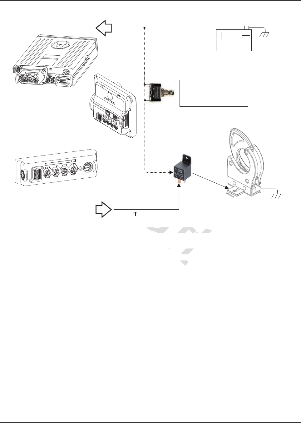
MN003109A01_aa
4-4 Options and Accessories Installation Remote-Mount Accessory Installation
Figure 4-4. Gunlock Switch Redundancy Diagram
NOTE: Refer to section 4.3.1 for information related to wiring and activation of VIPOUTs
The Y-cable KT000247A01 is primarily designed to allow for simultaneous operation of the Motorola
Branded SB9600 siren and still retain duplicate access to all the MAP (J2) connector pins located on
the APX 8500 remote TIB. Use of emergency accessories, speakers, programming cables, VIPS,
etc are possible via the P3 connector of Y-cable KT000247A01. The 26pin connector P2 does not
contain every signal from the legacy DB25 port, called J600 on the APX 7500. Therefore, some
legacy functionality (i.e. A+) is reduced with the APX 8500 remote mount configuration compared to
the APX 7500 remote mount configuration.
VIP OUT
GND
GND
Gunlock
Redundancy
Wiring
Car Battery
A+ into Transceiver
VIP OUT pin from
either J2 (Transceiver)
or J400 (control head)
Momentary or
time-out bypass
manual switch
Relay and Diode for
Activation of Gunlock
aft
witch Redundancy Diagram
witch Redundancy Diagra
d to wiring andto wiring
w for s
for
Draf
D
D
D
D
D
D
D
D
D
D
D
D
D
D
D
Dra
D
D
D
D
D
D
D
D
D
D
D
D
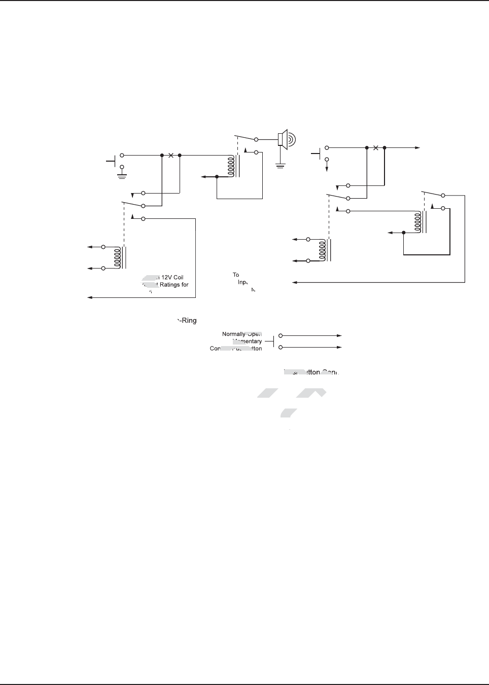
MN003109A01_aa
Options and Accessories Installation Remote-Mount Accessory Installation 4-5
4.2.5 Horn-Ring Transfer
Configure the Horn Relay for either Negative Contact or Positive Contact as shown in section 6.3 of
the siren/PA manual (6881093C18). Program the designated VIP-OUT line for “Horn-Ring Transfer”
and program the designated VIP-IN line for “Horn-Ring”.
Figure 4-5 shows wiring diagrams for connecting the Horn-Ring via a transfer relay for both negative
and positive ground systems. Refer to the siren/PA manual (6881093C18) for more information.
Figure 4-5. Siren/PA Horn-Ring Connections
4.2.6 Record Audio Out Jack of Transmit and Receive Audio
The use of Power Cable kit HKN6187_ (see Figure 2-34) provides access to both the transmitted
audio speech, as well as the received audio speech. This can be recorded with a standard tape
recorder using a 2.5 mm connector.
4.2.7 Earphone Jack
The use of Power Cable kit HKN6187_ (see Figure 2-34) provides the ability to use a standard
earphone/headset instead of the external speaker. Once a cable is plugged into this 2.5 mm jack, the
external speaker attached at the control head will turn mute.
To Horn
Break
Here
Horn
Ring
To Control Head VIP
Output Programmed for
Horn-Ring Transfer
To Control Head VIP
Input Programmed
for Horn-Ring
To SW B+ at
VIP Connector
N.C.
COM.
N.O.
To DIG. GND at
VIP Connector
+ 12V
Positive-Contact Horn-Ring
Negative-Contact Horn-Ring
Under Hood
Horn Relay Horn
Break
Here
Horn
Ring
To Control Head VIP
Output Programmed for
Horn-Ring Transfer
To Control Head VIP
Input Programmed
for Horn-Ring
Any SPDT Relay with 12V Coil
and Suitable Contact Ratings for
Vehicle Installation
N.C.
COM.
N.O.
+ 12V
Normally-Open
Momentary
Contact Pushbutton
To VIP Input Programmed for Horn-Ring
To DIG. GND at VIP Connector
Pushbutton Connections
NOTE: Locate Pushbutton
in a Location Convenient to
the Driver
To SW B+ at
VIP Connector
aft
orn-Ring Connection-Ring Connecti
Receiveece
4
4
Draft
ay with
ontact
n
Dr
Dr
y-Open
Mome
ntact Pushbutt
a
a
a
af
af
af
af
af
Pushbutton Con
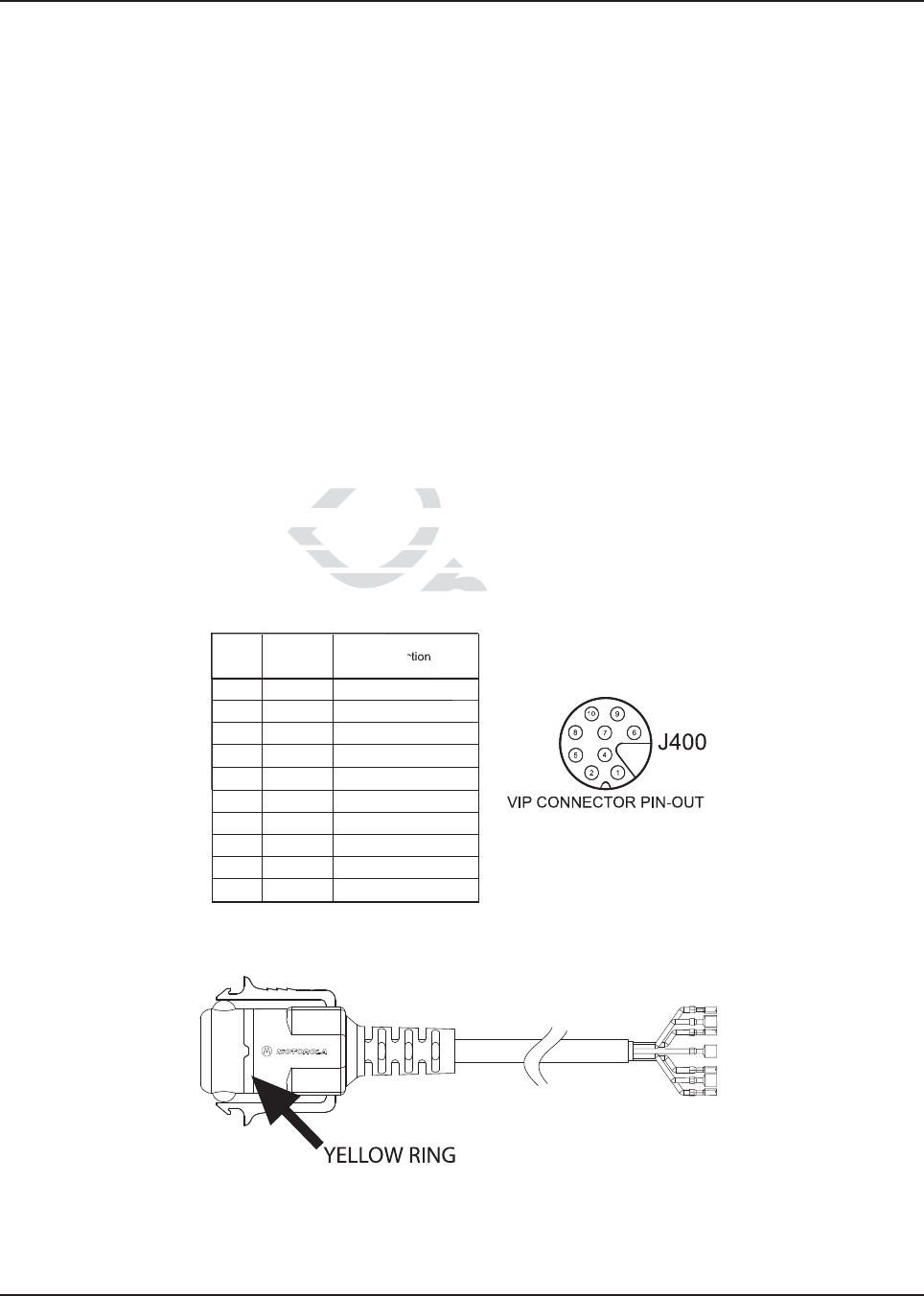
MN003109A01_aa
4-6 Options and Accessories Installation Vehicle Interface Port Overview
4.2.8 USB Data Cables
It is recommended that the USB 1.5 meter data cable HKN6163_ is used for both dash mount
configurations (at J2 connector) and for remote mount configurations (at J100 connector). This is
because the HKN6163_ has the emergency jumper present, which is necessary for correct dash
mount configurations. For interfacing at the MMP port, use Cable HKN6184_ which is a USB device
cable.
The USB 4 meter (15 feet) data cable HKN6172_ is recommended for remote mount configurations
only (at J2).
If the customer intends to use the HKN6172_ for dash mount configurations (at J2), the cable’s
26-pin connector must be opened and an emergency jumper-wire placed across pins 14 and 15.
Refer to Figure 4-1.
4.2.9 RS232 Cables
The following are RS232 cables. Although not compatible with CPS radio reading or programming,
they can be used for interfacing with RS232 accessories or RS232 computer programs. HKN6160_
is a 6 feet dash RS232 cable from J2 connector. HKN6161_ is a 20 feet dash RS232 cable from J2
connector.
4.3 Vehicle Interface Port Overview
The Vehicle Interface Port (VIP) allows the control head to operate outside circuits and to receive
inputs from outside the control head. There are three VIP outputs which are used for relay control.
There are also three VIP inputs which accept inputs from switches (remote mount only).
Figure 4-6. Remote Control Head Pinouts
Figure 4-7. HKN6196_ VIP Connector Detail
J400-1 RED SWB +
J400-2 GREEN GND
J400-3 - NO PIN
J400-4 - "VIP" detect: GPIO=HIGH
J400-5 BLUE VIP_OUT_1
J400-6 YELLOW VIP_OUT_2
J400-7 BLACK VIP_OUT_3
J400-8 WHITE VIP_IN_1 (VIP_IN GPIO)
J400-9 ORANGE VIP_IN_2 (VIP_IN GPIO)
J400-10 VIOLET VIP_IN_3
Radio
Pin
Number
VIP Cable
(HKN6196_)
Wire Color
Function
Dra
2
ort Overviewort Overvie
rt (VIP) allows the control
rt (VIP) allows the
trol head. There are thrtrol head. There are
ee
ts which accept inputs froms which accept inpu
raft
aft
t
t
t
t
t
ft
ft
ft
ft
ft
ft
ft
ft
ft
ft
ft
ft
ft
ft
ft
ft
ft
ft
ft
ft
ft
ft
ft
ft
ft
ft
ft
ft
ft
ft
a
a
a
a
ra
a
ra
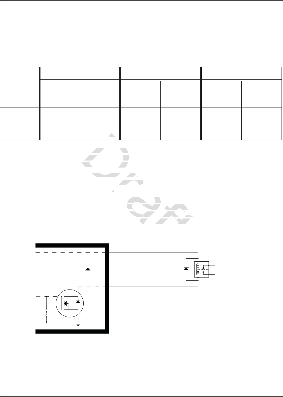
MN003109A01_aa
Options and Accessories Installation Vehicle Interface Port Overview 4-7
4.3.1 VIP Output Connections
The VIP output pins are on the back of the control head (J100 and J400), or the rear accessory port
(J2), as shown in Figure 2-10. Use these connections to wire control relays. One end of the relay
should connect to switched B+ voltage, while the other side connects to a software controlled ON/
OFF switch inside the control head. The relay can be normally on or normally off depending on the
configuration of the VIP outputs. There are three VIP output connections, as follows:
The function of these VIP outputs can be field programmed in the control head. Typical applications
for VIP outputs are external horn/lights alarm and horn ring transfer relay control. For further
information on VIP outputs, see the control head programming manual.
VIP OUT 1 and VIP OUT 2 can be accessed from either J100 or J400 connectors. This is to allow a
previously wired VIP OUT at J2 to move easily to J100. However, when any cable is inserted into
J400, J100 VIP OUTs are disabled.
When installing relays to the VIP OUT lines, a diode is necessary to prevent damage to the transistor
or MOSFET, due to “back EMF” when the field collapses on the relay coil. Some vendor relays
already come with this diode built-in, and other relays require the customer to install it. Figure 4-8
shows the proper placement of the diode across the relay coil. The transistor or MOSFET is located
inside the radio or the D.E.K. box.
Figure 4-8. Relay Coil
NOTE: See Appendix A: Replacement Parts Ordering to order relay’s for your VIP OUT applications.
Example relay hardware: TLN4533_ (relay without internal diode), HLN6969_ (relay with
internal back EMF protection diode), and HKN4258_ (relay wiring cable).
Table 4-1. VIP Output Connections
VIP OUT #
J400 J2 J100
SW B+ Pin
Number
On/Off
Switched Pin
Number
SW B+ Pin
Number
On/Off
Switched Pin
Number
SW B+ Pin
Number
On/Off
Switched Pin
Number
1 Red 1 5 (Blue) 24 18 24 18
2 Red 1 6 (Yellow) 24 19 24 19
3Red 17 (Black)NANANANA
N.C.
N.O.
Relay
G
D
S
VIPout
SW B+
Note:
To 'activate' a VIPOUT, you have to ground the VIPOUT, such that the
current now flows thru the relay coil to GND through a MOSFET inside
the radio or control head, which causes the relay wiper to toggle. The
MOSFET of a VIPOUT should never be used to directly drive an
accessory. The MOSFET should be used to control an external relay.
Protection
Diode
Draft
outputs can be foutputs can be
ernal horn/lights alarm ernal horn/lights al
puts, see t
puts,
he control headcontr
2 can be acce2 can be acc
ssed from essed
J2 to move easily to2 to move easily
J100
bled.d.
U
T lines, a diode is necessaes, a diode is
the field cohe field co
llapses on the llapses on the
otheothe
r relays require the cu
r relays require the c
cross the relay coil. The t
oss the relay coil. Th
D
kk
)
)
D
t
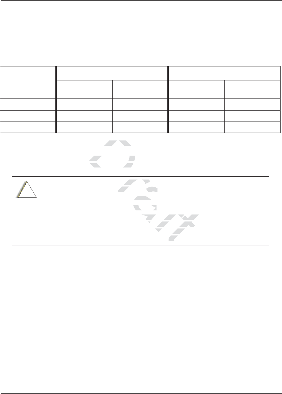
MN003109A01_aa
4-8 Options and Accessories Installation Vehicle Interface Port Overview
4.3.2 VIP Input Connections
The VIP input pins are only available on the back of the control head (remote mount). These
connections control inputs from switches. One side of the switch connects to ground while the other
side connects to a buffered input on the control head. The switch can be normally closed (NC) or
normally open (NO) depending on the configuration of the VIP inputs. There are three VIP input
connections, as follows:
NOTE: Remote Mount requires the VIP cable to be attached to J400.
MCH installations require the VIP inputs to be connected to the head assigned ID #1. See
Section 2.2.2.4 for further information.
Table 4-2. VIP Input Connections
VIP IN #
J400 J2
Ground Pin
Number
On/Off Switched
Pin Number
Ground Pin
Number
On/Off Switched
Pin Number
1 2 (green) 8 (white) NA NA
2 2 (green) 9 (orange) NA NA
3 2 (green) 10 (violet) NA NA
APX mobile radios equipped with the following features are capable of transmitting
automatically, even if the radio is turned off:
• Automatic Vehicle Location
• Other Special Data Products
All APX mobile have accessory connector pins 14 and 15 connected together to allow
the radio to power down. Opening this connection by REMOVING the accessory
connector, or otherwise failing to maintain a normally closed path, could, if left
unchecked, drain the vehicle battery, and possibly cause transmissions to occur.
!
C a u t i o n
Draft
s the VIP cas the VIP ca
s require the VIs requ
P inputs P in
or further information.r further informati
ipped with the following fewith the foll
radio is turned off:dio is turned off:
cle Locationocation
a ProductsProducts
ector pins 14 and 15 conn
ector pins 14 and 15 co
connection by REMO
connection by REM
a normally closa normally c
ssibly causbly c
D
Dr
t

MN003109A01_aa
Options and Accessories Installation Accessory Connector Assembly Details (P2) 4-9
4.4 Accessory Connector Assembly Details (P2)
The APX mobile accessory connector assembly is mounted on the right rear of the radio, opposite
the antenna and adjacent to the power connector. It is fastened to the radio via jackscrews and held
together by the two cover screws. It is a multi-functional connector that allows for many different
types of adaptations. All approved accessory wires are securely strain-relieved through the exiting
slots at the back of the accessory connector assembly. The terminations that are supplied with all
accessories are designed to be fully engaged and locked into the plug connector (6680163F01).
They can also be detached for service with the assistance of a terminal removal tool. The accessory
connector assembly can be serviced multiple times for future installation upgrades.
The accessory connector assembly, supplied with every APX mobile dash-mounted radio, is
equipped with a 26-pin plug assembly, two covers, two jackscrews, two cover screws, one
emergency jumper, one ignition sense cable assembly, and one speaker pigtail. The jumper is
provided to complete the circuit for emergency mode. If this circuit becomes open, the radio will be
set to emergency mode.
39800834F05 is the crimping pin part number for use with any wires used inside the accessory cable
connector.
4.4.1 Disassembly and Assembly
4.4.1.1 Disassembly
1. Disconnect the negative terminal from the vehicle’s battery. Make sure that the battery cable
is secured such that it will not power the vehicle’s electrical system.
2. Unscrew both jackscrews completely.
3. Pull the accessory connector assembly out from the radio.
4. Loosen both cover screws, but do not remove them completely.
5. Pull the jackscrews away from the plug and hold them back.
6. Pry apart the accessory connector assembly covers.
7. Attach any new wire to its proper location by pushing in the male terminal. When you hear a
pop, the wire is engaged. To verify that the wire is engaged, tug gently on the wire and be
sure it does not come out. Do not overload the wire: severe damage will result to the plug.
Draft
mblymbly
negative terminal negative terminal
from the
at it will not power the vehat it will not power
ews completely. mpletely.
ctor assembly out from thetor assembly out fr
ut do not remove them como not remove them com
he plug and hold them back
e plug and hold them ba
ssembly covers. sembly covers.
on by pushing in thby pushing in th
wire is engae is e
e wire:wir
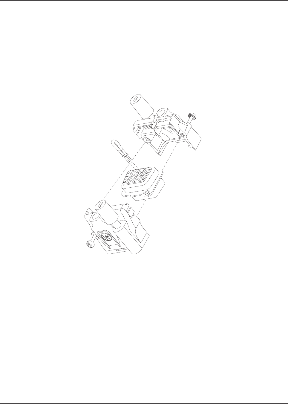
MN003109A01_aa
4-10 Options and Accessories Installation Accessory Connector Assembly Details (P2)
4.4.1.2 Assembly
1. Place the plug in one cover. Be sure that the flange of the plug is in the slot of the cover.
See Figure 4-9.
2. Push the jackscrew through the plug to hold it in.
3. Position each wire across the strain-relief features in the cover. Avoid damaging loads on the
plug by allowing some slack in each wire in the accessory connector assembly’s wire
chamber.
4. Place the second cover onto the plug. Be sure that the flange is protruding through both
covers.
Figure 4-9. Exploded View of Accessory Connector Assembly (HLN6863_)
5. Squeeze the covers together bending the wires in the strain-relief features. You may need a
pair of pliers to seat the assembly covers.
6. Once the covers are fully seated, fasten them with the cover screws. Tighten the screws
firmly but do not over-tighten them. Be sure none of the wires are pinched.
7. Reattach the accessory connector assembly to the back of the radio and fasten it by
finger-tightening the jackscrews to prevent any loosening.
NOTE: See APX Mobile Basic Service Manual for more detailed descriptions of these pins and other
connectors located in the APX mobile radio.
t
Draft
Dr
Dr
Dr
Dra
Dra
r
Dr
Dr
Dr
Dr
ra
r
ra
ra
a
r
r
ra
D
Dr
D
D
Dr
Dr
Dr
Dr
Dr
Dr
Dr
Dr
Dr
Dr
ra
ra
ra
r
r
ra
Dr
Dr
Dr
Dr
Dr
Dr
Dr
Dr
Dr
Dr
Dr
r
Dr
Dr
Dr
Dr
Dr
Dr
Dr
Dr
Dr
Dr
Dr
D
D
D
D
D
Dr
Dr
Dr
Dr
Dr
Dr
Dr
Dr
Dr
Dr
ra
Dr
Dr
Dr
Dr
r
r
Dr
Dr
Dr
Dr
Dr
Dr
Dr
Dr
Dr
Dr
Dr
Dr
Dr
Dr
Dr
Dr
Dr
Dr
Dr
Dr
Dr
Dr
Dr
Dr
Dr
Dr
Dr
Dr
Dr
Dr
Dr
Dr
ra
Dr
ra
Dr
Dr
r
D
r
Dr
Dr
Dr
Dr
Dr
Dr
Dr
Dr
Dr
Dr
Dr
Dr
Dr
Dr
D
Dr
Dr
D
Dr
Dr
D
Dr
D
Dr
Dr
r
ra
ra
Dr
Dr
Dr
Dr
Dr
Dr
Dr
Dr
D
Dr
Dr
Dr
D
Dr
Dr
Dr
D
Dr
Dr
Dr
ra
Dr
Dr
Dr
r
r
r
D
Dr
Dr
D
Dr
D
D
D
D
D
D
D
D
D
Dr
D
ra
Dr
ra
r
r
Dr
r
Dr
Dr
Dr
Dr
Dr
Dr
Dr
Dr
Dr
D
D
D
Dr
Dr
Dr
Dr
ra
Dr
Dr
D
D
Dr
D
D
Dr
Dr
D
Dr
D
D
D
D
D
D
D
D
D
D
r
Dr
Dr
Dr
Dr
Dr
Dr
Dr
Dr
Dr
Dr
Dr
Dr
Dr
Dr
Dr
Dr
Dr
Dr
D
Dr
Dr
ra
r
D
D
D
D
D
D
D
D
Dr
Dr
Dr
Dr
Dr
D
D
Dr
r
D
Dr
Dr
Dr
r
r
Dr
Dr
Dr
Dr
Dr
Dr
Dr
Dr
Dr
r
Dr
Dr
Dr
Dr
Dr
Dr
Dr
Dr
D
ra
Dr
Dr
Dr
Dr
Dr
Dr
Dr
Dr
Dr
Dr
Dr
Dr
Dr
Dr
Dr
Dr
Dr
Dr
Dr
D
D
D
D
D
D
D
D
Dr
Dr
Dr
Dr
Dr
Dr
Dr
Dr
Dr
Dr
Dr
Dr
Dr
D
Dr
D
Dr
Dr
Dr
Dr
Dr
D
Dr
D
Dr
Dr
Dr
Dr
Dr
r
Dr
Dr
D
Dr
Dr
Dr
Dr
Dr
Dr
Dr
Dr
Dr
Dr
Dr
Dr
D
Dr
D
Dr
Dr
Dr
Dr
Dr
D
Dr
D
Dr
Dr
Dr
Dr
Dr
Dr
Dr
Dr
r
Dr
Dr
Dr
Dr
Dr
Dr
Dr
Dr
D
Dr
Dr
Dr
Dr
Dr
Dr
Dr
D
Dr
D
Dr
Dr
Dr
Dr
Dr
Dr
Dr
Dr
Dr
Dr
Dr
Dr
D
D
D
D
D
D
Dr
D
Dr
Dr
Dr
Dr
D
Dr
Dr
Dr
D
D
Dr
Dr
Dr
Dr
Dr
D
Dr
Dr
D
Dr
Dr
Dr
Dr
Dr
Dr
Dr
Dr
Dr
Dr
Dr
Dr
Dr
Dr
Dr
Dr
Dr
Dr
Dr
Dr
Dr
Dr
Dr
r
a
r
Dr
Dr
Dr
Dr
Dr
Dr
Dr
ra
ra
ra
Dr
Dr
Dr
ra
r
r
Dr
Dr
Dr
Dr
r
Dr
Dr
Dr
Dr
Dr
ra
ra
Dr
Dr
Dr
Dr
Dr
Dr
Dr
r
Dr
Dr
Dr
D
Dr
Dr
Dr
Dr
Dr
Dr
Dr
Dr
Dr
Dr
r
Dr
Dr
D
Dr
Dr
Dr
Dr
Dr
Dr
Dr
Dr
Dr
Dr
Dr
Dr
Dr
Dr
Dr
Dr
Dr
Dr
Dr
Dr
Dra
ra
ra
ra
ra
Dr
Dr
Dr
Dr
Dr
Dr
Dr
Dr
Dr
Dr
Dr
Dr
r
Dr
Dr
Dr
Dr
Dr
Dr
Dr
Dr
Dr
Dr
Dr
Dr
Dr
Dr
Dr
Dr
Dr
Dr
Dr
Dr
Dr
Dr
Dr
Dr
Dr
Dr
Dr
Dr
Dr
Dr
Dr
Dr
Dr
Dr
ra
ra
ra
a
r
r
D
D
Dra
D
ra
D
ra
r
ra
ra
ra
Dra