Motorola Solutions 92FT7089 Mobile 2-Way Portable Radio with Bluetooth, Bluetooth LE and WiFi User Manual Installation Manual 4 of 4
Motorola Solutions, Inc. Mobile 2-Way Portable Radio with Bluetooth, Bluetooth LE and WiFi Installation Manual 4 of 4
Contents
Installation Manual 4 of 4
MN003109A01_aa
Options and Accessories Installation Motorola Branded SB9600 Siren Connection to APX 8500 4-11
4.5 Motorola Branded SB9600 Siren Connection to APX 8500
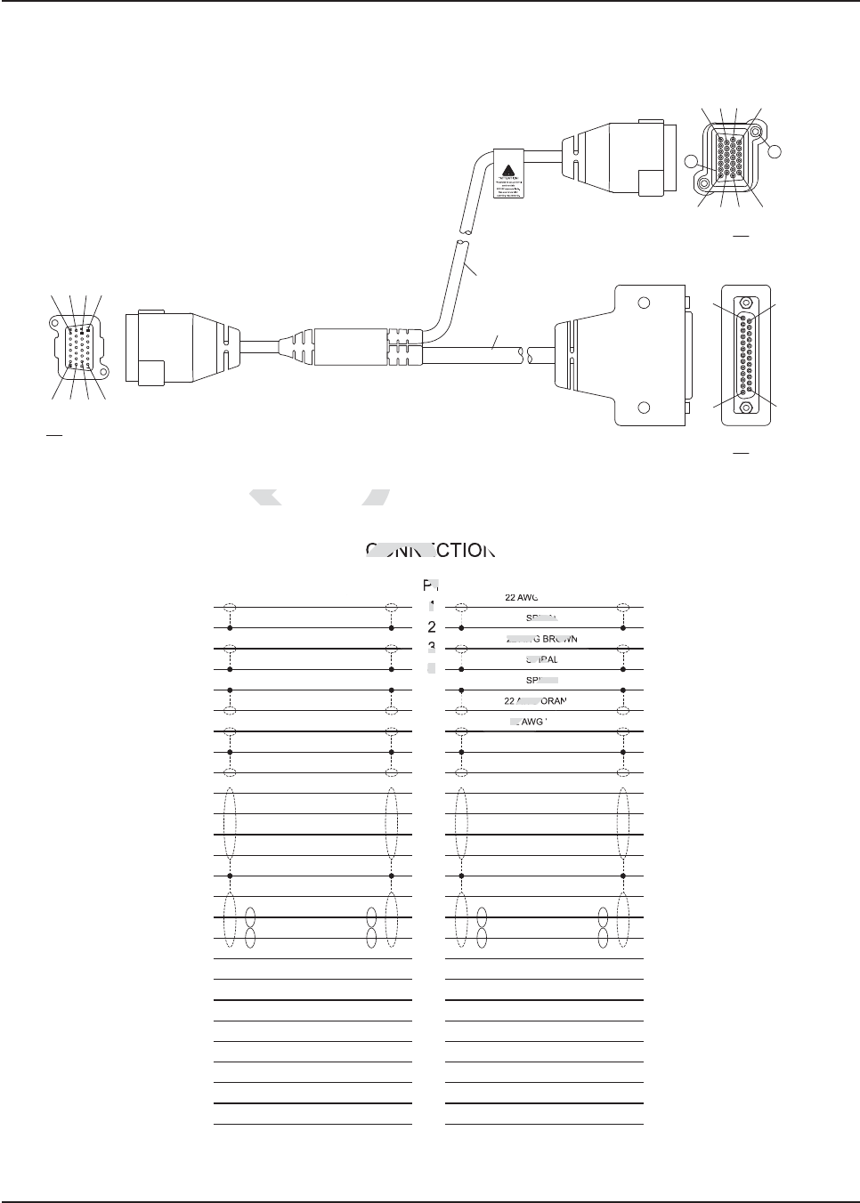
Figure 4-10. J600 Accessory Connector Y-Cable KT000247A01
Figure 4-11. Pinout for cable KT000247A01
CABLE 2
CABLE 1
P1
P2
P3
#21 #11 #8 #1
#26 #20 #13 #7 #13
#1
#7 #13 #20 #26
#1 #8 #14 #21
#25
#14
340
130
22 AWG YELLOW
SPIRAL
22 AWG BROWN
SPIRAL
SPIRAL
22 AWG ORANGE
22 AWG WHITE
SPIRAL
22 AWG BLACK
22 AWG PINK
22 AWG PURPLE
22 AWG GRAY
22 AWG TAN
22 AWG DRAIN
22 AWG BLUE
22 AWG RED
22 AWG GREEN
18 AWG RED
18 AWG YELLOW
22 AWG LIGHT BLUE
22 AWG LIGHT GREEN
18 AWG ORANGE
18 AWG BROWN
22 AWG BROWN/WHITE
22 AWG BLACK/WHITE
18 AWG BLACK
P3
1
CUT
CUT
4
5
6
7
CUT
CUT
10
11
12
13
14
15
16
17
18
19
20
21
22
23
24
25
26
22 AWG YELLOW
SPIRAL
22 AWG BROWN
SPIRAL
SPIRAL
22 AWG ORANGE
22 AWG WHITE
SPIRAL
22 AWG BLACK
22 AWG PINK
22 AWG PURPLE
22 AWG GRAY
22 AWG TAN
22 AWG DRAIN
22 AWG BLUE
22 AWG RED
22 AWG GREEN
18 AWG RED
18 AWG YELLOW
22 AWG LIGHT BLUE
22 AWG LIGHT GREEN
18 AWG ORANGE
18 AWG BROWN
22 AWG BROWN/WHITE
22 AWG BLACK/WHITE
18 AWG BLACK
P2
10/11
5
14
2
3
CUT
CUT
19
23
8/17
4
CUT
CUT
18/21
13
1
CUT
15
CUT
25
6/9
CUT
12
20/22
16
24
P1
1
2
3
4
5
6
7
8
9
10
11
12
13
14
15
16
17
18
19
20
21
22
23
24
25
26
CONNECTION
Dr
-10. J600 Accessory Con
10. J600 Accesso
D
Draft
ra
a
a
ra
ra
ra
a
a
af
af
aft
aft
ft
ft
t
t
af
af
af
af
af
af
af
af
af
af
f
f
f
f
f
SPIRAL
22 AWG BROWN
SPIRAL
PIRAL
AWG O
22 A
P1
1
2
3
4
CONNEC
MN003109A01_aa
4-12 Options and Accessories Installation Motorola Branded SB9600 Siren Connection to APX 8500
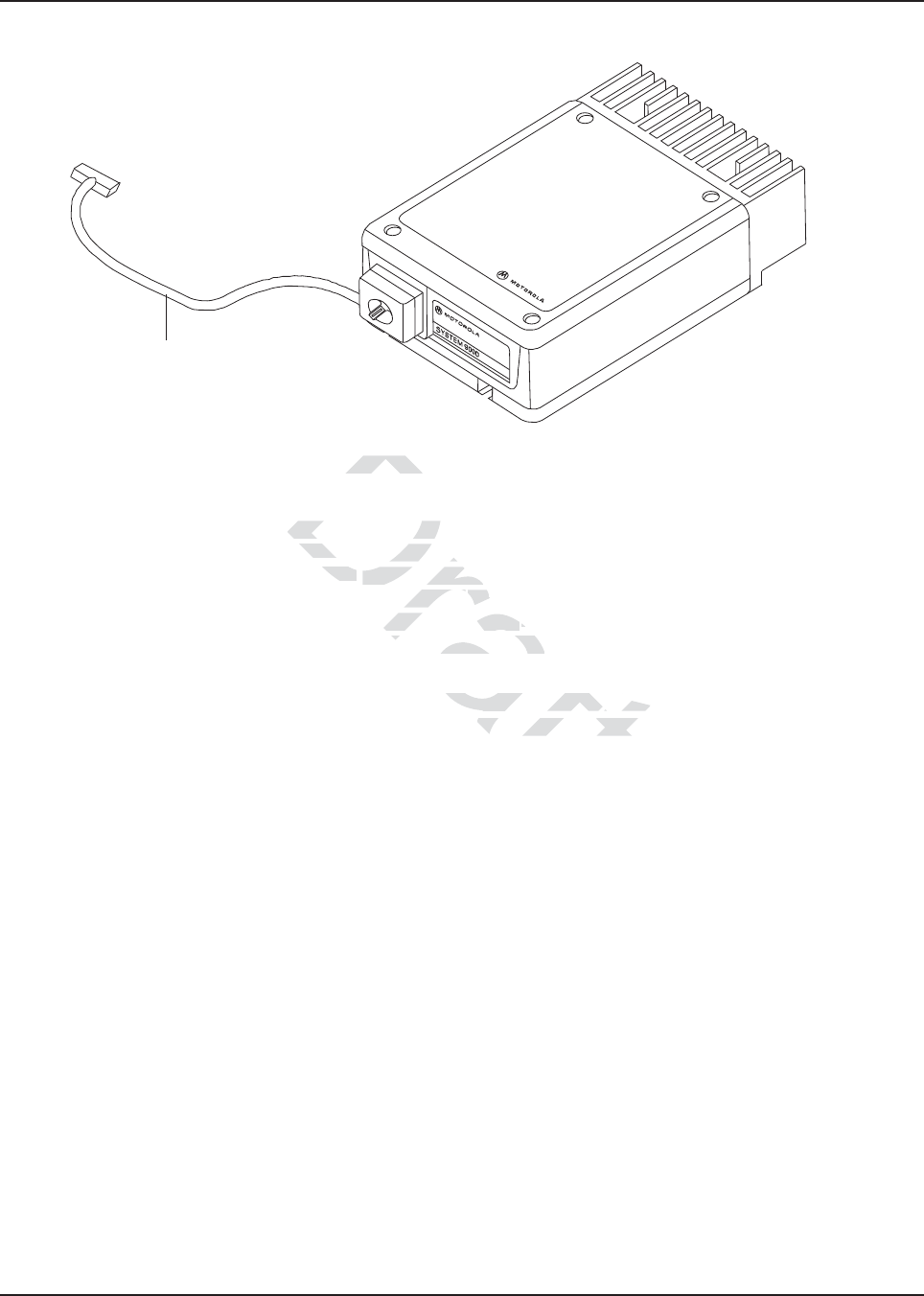
Figure 4-12. Interfacing the Y-cable to the Motorola Branded SB9600 Siren and External Accessories
The Y-cable KT000247A01 is primarily designed to allow for simultaneous operation of the Motorola
Branded SB9600 siren and still retain duplicate access to all the MAP (J2) connector pins located on
the APX 8500 remote TIB. Use of emergency accessories, speakers, programming cables, VIPS,
etc are possible via the P3 connector of Y-cable KT000247A01. The 25pin connector P2 does not
contain every signal from the legacy DB25 port, called J600 on the APX 7500. Therefore, some
legacy functionality (i.e. A+) is reduced with the APX 8500 remote mount configuration compared to
the APX 7500 remote mount configuration.
NOTE: Only USB 1.5 meter data cable HKN6163_ is approved for use in series with the Y-cable
KT000247A01 at connector P3. USB 4 meter data cable HKN6172_ is not approved for use
in series with the Y-cable at connector P3.
Siren Cable
Draft
o the Motoo the Mot
01 is primarily designed t
01 is primarily desig
d still retaind still
duplicate acceduplicat
se of se of
emergency accessoremergency acc
nector of Y-cablf Y-cabl
e KT00024e K
cy DB25 port, calleDB25 port, calle
d J600 d
ed with the APd with the A
X 8500 remoX 850
on.
N6163_ is aN6163_ is
pproved for use
pproved for u
meter data cable HKN6
meter data cable HK
MN003109A01_aa
Options and Accessories Installation Compatibility of Emergency when Attaching a Motorola Branded SB9600 Siren4-
4.6 Compatibility of Emergency when Attaching a Motorola Branded
SB9600 Siren
When using emergency footswitch or pushbutton with siren/PA configuration, REMOVE pin 8
(emergency) from the siren connector of the HKN4363_ siren cable as follows:
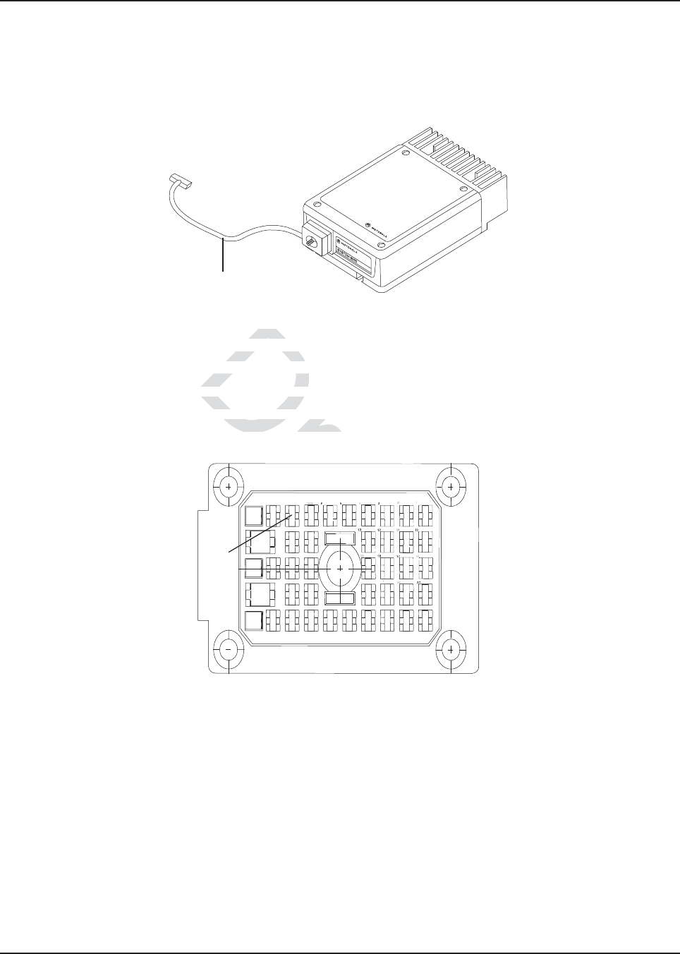
Figure 4-13. Field adjustment for Emergency Operation with Siren Accessory
1. Remove the knob from the siren/PA cable connector.
2. Remove all four screws from the connector in the siren/PA cable.
3. Open the connector cap and locate pin 8.
4. Using the contact removal tool (6684690C02), remove pin 8 from the connector.
5. Put the connector cap in place and proceed to reinstall the four screws and the knob.
Figure 4-14. Location for Pin 8
Siren Cable
1
2
3
4
5
67 8
9
A
B
2930
3132
3334
35
36
37
2324
25
26
16
17
18
19
10
11
12
13
1415
20
21
22
27
28
Pin 8
Dra
the sirethe sire
ews from the cews from the
ctor cap and locate pinctor cap and locat
ct removal tool (6684690Cct removal tool (6
cap in place and proceed toap in place and pro
raft
ra
ft
aft
aft
f
af
af
af
f
ft
ft
ft
ft
ft
ft
t
ft
ft
ft
ft
ft
ft
ft
ft
ft
ft
ft
ft
ft
ft
ft
ft
ft
ft
ft
ft
ft
ft
ft
ft
ft
ft
ft
ft
ft
ft
ft
ft
ft
ft
ft
ft
ft
ft
ft
t
t
t
t
t
f
f
f
f
f
f
af
af
af
af
af
af
af
af
t
t
t
ft
ft
ft
ft
ft
ft
ft
aft
aft
aft
ft
aft
aft
ft
aft
aft
aft
aft
aft
aft
aft
af
af
af
f
af
af
f
ft
af
ft
ft
ft
ft
ft
af
af
a
a
af
af
af
a
a
a
a
a
a
a
a
a
a
a
ft
f
f
a
1
2
4
24
16
6
19
11
2

MN003109A01_aa
4-14Options and Accessories Installation Compatibility of Emergency when Attaching a Motorola Branded SB9600 Si-
Notes
Draft
Chapter 5 Motorcycle Radio Installation
5.1 Motorcycle Radio Description
The motorcycle model includes all the same components in the standard radio. The following
paragraphs describe the unique items provided with the motorcycle models.
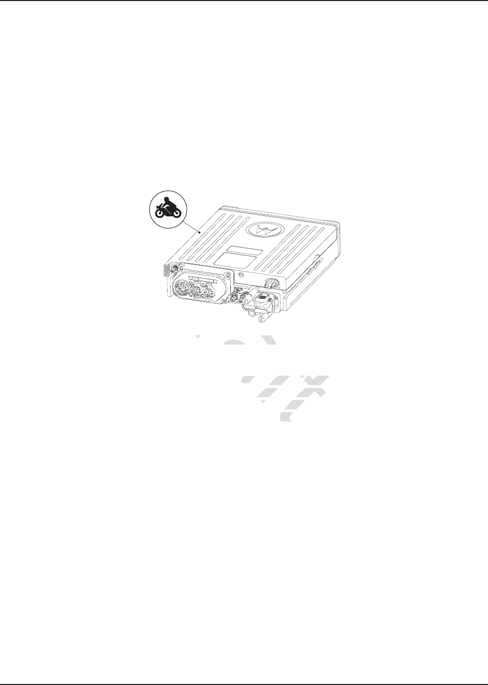
A small label is included with the motorcycle radio, which can be placed on the radio to identify it as
a motorcycle radio. The label should be placed on a flat and protected area to avoid damage during
handling. See Figure 5-1.
Figure 5-1. Identification of a Motorcycle Radio by Using a Label
5.1.1 Transceiver Enclosure
The transceiver is mounted in the weather-resistant enclosure that consists of a bottom housing and
a hinged top cover. The top cover has a locking latch that requires a key to open. The enclosure is
mounted above the rear motorcycle wheel, oriented so that the lock is forward and the hinged cover
opens toward the rear of the motorcycle. The bottom housing has a grommeted hole for cable entry
and weep holes to permit water drainage.
The enclosure is mounted on the motorcycle with a universal mounting plate and shock and vibration
isolators. A large, braided ground-strap (installed between the mounting plate bolts and the
motorcycle frame) grounds the transceiver.
5.1.2 Control/Display Unit
All radio functions, except push-to-talk (PTT), are activated from the control head, which also is
weather-resistant. The control head and the external speaker are mounted for easy access near the
center of the handlebars. The control head is positioned for unobstructed viewing, and it may be
tilted on the horizontal axis for ease of viewing. The microphone cable port on the front of the control
head is plugged and is not used.
5.1.3 Control Head Cable
The control-head cable connects the control head to the transceiver. The cable is routed along the
motorcycle’s frame and has weather-resistant connections at both ends. Excess cable is coiled
under the transceiver inside the weather-resistant enclosure.
Each end of the cable is strain-relieved with jackscrews at the control head and the transceiver.
The cable is shielded to reduce the effects of radio frequency interference and ignition sense noise.
Draft
tion of tio
a Motorcycle Radioa Motorcycle
resistantsista
enclosure that c
enclosure tha
t
g latch that requiresg latch that require
ted ed
so that the that
m housinghou
Dra
ra
r
Dr
Dr
Dr
Dr
Dr
Dr
Dr
Dr
Dr
Dr
Dr
D
Dr
Dr
Dr
D
Dr
D
D
D
D
D
D
D
D
D
D
D
D
D
D
D
D
D
D
D
D
D
D
D
D
D
D
D
D
D
D
D
D
D
D
D
D
D
D
D
D
D
D
D
D
D
D
D
D
D
D
D
D
D
D
D
D
D
D
D
D
D
D
D
D
D
D
D
D
D
D
D
D
D
D
D
D
D
D
D
D
D
D
D
D
D
D
D
D
D
D
D
D
D
D
D
D
D
D
D
D
D
D
D
D
D
D
D
D
D
D
D
D
D
D
D
D
D
D
D
D
D
D
D
D
D
D
D
D
D
D
D
D
D
D
D
D
D
D
D
D
D
D
D
D
D
D
D
D
D
D
D
D
Dr
D
Dr
D
Dr
Dr
D
D
D
D
D
D
D
D
D
D
D
D
D
D
Dr
Dr
D
Dr
Dr
D
D
Dr
D
Dr
Dr
D
D
D
D
D
D
D
D
D
D
D
D
D
D
D
D
D
D
D
D
D
D
D
D
D
D
D
D
D
D
D
D
D
D
D
D
D
D
D
D
D
D
D
D
D
D
D
D
D
D
D
D
D
D
D
D
D
a
D
D
D
Dr
D
D
D
Dr
Dr
Dr
D
D
D
D
D
D
D
D
D
D
D
D
D
D
D
D
D
D
D
D
Dr
D
r
r
r
r
r
r
r
Dr
Dr
Dr
D
Dr
Dr
r
Dr
Dr
Dr
Dr
r
Dr
Dr
Dr
r
Dr
Dr
r
D
r
D
D
r
r
D
D
Dr
D
Dr
D
D
D
Dr
Dr
Dr
Dr
D
D
D
D
D
D
D
Dr
Dr
D
D
D
D
D
D
D
D
D
D
D
D
D
D
D
D
D
D
D
Dr
Dr
D
D
D
Dr
Dr
Dr
D
Dr
Dr
Dr
Dr
Dr
Dr
Dr
Dr
Dr
Dr
Dr
Dr
Dr
Dr
r
D
Dr
D
D
D
Dr
r
r
D
r
r
r
r
r
r
r
r
r
r
r
r
r
r
r
Dr
D
D
Dr
Dr
D
D
D
D
D
Dr
Dr
D
D
D
D
Dr
D
Dr
Dr
D
D
D
D
D
Dr
Dr
Dr
D
D
D
D
D
D
D
D
D
D
D
D
D
D
D
D
D
D
D
D
D
D
D
D
D
D
D
D
D
D
D
D
D
D
D
D
D
D
D
D
D
D
D
D
D
D
D
r
r
r
r
r
D
D
Dr
Dr
D
Dr
D
Dr
D
Dr
D
D
D
D
D
D
D
D
D
D
D
D
D
D
D
D
D
D
D
D
D
D
D
D
D
D
D
D
D
D
D
D
D
D
D
D
D
D
D
D
D
D
D
D
D
D
a
a
a
r
Dr
Dr
D
Dr
Dr
Dr
Dr
Dr
Dr
Dr
Dr
Dr
Dr
Dr
D
D
D
D
D
D
D
D
D
D
r
r
Dr
Dr
r
r
r
Dr
r
r
r
r
r
r
r
r
r
r
r
r
r
r
r
Dr
Dr
D
Dr
Dr
Dr
Dr
Dr
D
D
D
D
D
r
r
r
Dr
D
D
D
D
a
a
a
a
Dr
Dr
Dr
a
a
a
D
D
D
Dr
Dr
Dr
Dr
Dr
Dr
Dr
Dr
Dr
Dr
Dr
Dr
Dr
Dr
Dr
Dr
Dr
Dr
Dr
Dr
Dr
Dr
Dr
Dr
Dr
Dr
Dr
Dr
Dr
Dr
Dr
Dr
Dr
Dr
Dr
Dr
Dr
Dr
Dr
Dr
Dr
Dr
Dr
Dr
Dr
Dr
Dr
D
D
D
D
D
D
D
D
D
D
D
D
D
D
D
D
D
D
D
D
D
D
D
D
D
D
D
D
D
D
D
D
D
D
D
D
D
D
D
D
D
D
D
D
D
D
D
D
D
D
D
D
D
D
D
D
D
D
D
D
D
D
D
D
D
D
D
D
D
D
D
D
D
D
D
D
D
D
D
D
D
D
D
D
D
D
D
D
D
D
D
D
D
D
D
D
D
D
D
D
D
D
D
D
D
D
D
D
D
D
D
D
D
D
D
D
D
D
D
D
D
D
D
D
D
D
D
D
D
D
D
D
D
D
D
D
D
D
D
D
D
D
D
D
D
D
D
D
D
D
D
D
D
D
D
D
D
D
D
D
D
D
D
D
D
D
D
D
D
D
D
D
D
D
D
D
D
D
D
D
D
D
D
D
D
D
D
D
D
D
D
D
D
D
D
D
D
D
D
D
D
D
D
D
D
D
D
D
D
D
D
D
D
D
Dr
D
D
D
Dr
Dr
Dr
Dr
D
D
D
D
D
D
Dr
D
Dr
Dr
Dr
Dr
Dr
Dr
D
D
D
D
D
D
D
D
D
D
D
D
D
D
D
D
D
D
D
D
D
D
D
D
D
D
D
D
D
D
D
D
D
D
D
D
D
D
D
D
D
D
D
D
Dr
D
D
Dr
Dr
D
D
D
D
D
D
D
D
D
D
D
D
D
D
Dr
Dr
Dr
D
Dr
D
D
D
D
D
D
D
D
D
D
D
D
D
D
D
D
D
D
D
D
D
D
D
D
D
D
D
D
D
D
D
D
D
D
D
D
D
D
D
D
D
D
D
D
D
D
D
D
D
D
D
D
D
D
D
D
D
D
D
D
D
D
D
D
D
D
D
D
D
D
D
D
D
D
D
D
D
D
D
D
D
D
D
D
D
D
D
D
Dr
Dr
Dr
Dr
D
Dr
D
D
Dr
Dr
Dr
D
D
D
D
D
D
D
D
D
D
D
D
D
D
D
D
D
D
D
D
D
D
D
D
D
D
D
D
D
D
D
D
D
D
D
D
Dr
Dr
Dr
Dr
Dr
Dr
Dr
Dr
Dr
Dr
Dr
Dr
Dr
Dr
Dr
Dr
Dr
Dr
Dr
Dr
Dr
D
D
D
D
D
D
D
D
D
D
Dr
Dr
Dr
Dr
Dr
Dr
Dr
D
D
D
D
D
D
D
D
D
D
Dr
Dr
Dr
Dr
D
D
D
D
D
D
D
D
D
D
Dr
D
D
D
D
D
D
D
D
D
D
D
D
D
D
D
D
D
D
D
D
D
D
D
D
D
D
D
D
D
D
D
Dr
D
D
D
Dr
Dr
Dr
r
r
a
D
r
a
a
Dr
Dr
Dr
Dr
Dr
Dr
Dr
Dr
Dr
Dr
Dr
r
Dr
Dr
Dr
Dr
Dr
Dr
Dr
Dr
Dr
Dr
Dr
Dr
Dr
Dr
Dr
Dr
Dr
Dr
Dr
Dr
Dr
Dr
Dr
Dr
Dr
Dr
Dr
Dr
Dr
Dr
Dr
Dr
D
r
r
Dr
Dr
Dr
Dr
Dr
Dr
Dr
Dr
Dr
Dr
Dr
Dr
D
D
D
D
D
D
D
D
D
D
D
D
r
r
r
Dr
Dr
r
Dr
r
r
r
r
r
r
r
r
r
r
r
r
r
r
r
r
r
r
r
r
r
r
r
r
r
r
r
r
Dr
Dr
Dr
Dr
Dr
Dr
Dr
Dr
r
r
r
r
r
r
r
r
r
r
r
r
r
r
r
r
r
r
r
r
r
r
r
r
r
D
Dr
r
r
r
Dr
Dr
D
D
r
D
D
D
D
D
D
D
D
D
D
D
D
D
D
D
D
r
r
r
r
r
r
r
r
D
Dr
Dr
Dr
D
Dr
D
D
Dr
Dr
D
Dr
Dr
D
Dr
Dr
Dr
Dr
Dr
Dr
Dr
Dr
Dr
Dr
Dr
Dr
Dr
D
D
D
D
D
D
D
D
D
D
D
D
D
D
D
D
D
D
D
D
D
D
D
D
D
D
D
D
D
D
D
Dr
D
Dr
D
D
D
D
D
D
D
D
D
D
D
D
D
D
D
D
D
D
D
D
Dr
Dr
Dr
Dr
Dr
Dr
D
D
D
D
D
D
D
D
D
D
D
D
D
D
D
D
D
D
D
D
D
D
D
D
D
D
D
D
D
D
D
D
D
D
D
D
D
D
D
D
D
D
D
D
D
D
D
D
D
D
D
D
D
D
D
D
D
D
D
D
D
D
D
D
D
D
D
D
D
D
D
D
D
D
D
D
D
Dr
Dr
r
r
Dr
Dr
Dr
Dr
Dr
Dr
Dr
Dr
Dr
Dr
Dr
Dr
r
Dr
Dr
Dr
Dr
Dr
Dr
Dr
Dr
Dr
Dr
Dr
Dr
Dr
r
r
r
r
r
Dr
Dr
Dr
r
r
r
Dr
Dr
Dr
Dr
Dr
Dr
Dr
r
Dr
Dr
Dr
Dr
Dr
Dr
Dr
Dr
r
r
Dr
Dr
Dr
r
r
Dr
r
r
r
r
r
r
Dr
Dr
Dr
Dr
r
r
r
r
r
r
r
r
r
r
r
r
r
r
r
r
r
r
r
r
r
r
r
r
r
r
r
r
r
r
r
r
r
r
r
r
D
D
D
Dr
Dr
D
D
D
D
D
D
D
D
D
D
D
D
D
D
Dr
D
D
D
Dr
D
D
D
D
D
D
D
D
D
D
D
D
D
Dr
D
D
D
Dr
Dr
D
D
Dr
D
D
D
D
D
D
D
D
D
D
D
D
D
D
D
D
D
D
D
D
D
D
Dr
Dr
Dr
Dr
Dr
D
D
D
D
D
D
D
Dr
D
D
D
D
D
D
D
D
Dr
Dr
D
D
D
D
D
Dr
D
D
D
D
D
D
D
D
D
D
D
D
D
D
D
D
D
D
D
D
D
D
D
D
D
D
D
D
D
D
D
D
D
D
D
D
D
D
D
D
D
D
Dr
D
D
D
Dr
D
D
D
D
D
D
D
D
D
Dr
D
Dr
D
D
Dr
D
D
D
D
D
D
D
D
D
D
D
D
D
D
D
D
D
D
D
D
D
D
D
D
D
D
D
D
D
D
Dr
D
D
D
D
D
D
D
Dr
Dr
Dr
D
D
D
D
D
D
D
D
D
D
D
D
D
D
D
D
D
D
Dr
D
D
D
D
Dr
D
D
D
D
D
D
D
D
Dr
Dr
Dr
Dr
D
D
D
D
D
D
D
D
D
D
D
D
D
D
D
D
D
D
D
D
D
D
D
D
D
D
D
Dr
D
D
D
Dr
Dr
Dr
Dr
D
D
Dr
D
D
D
Dr
D
D
D
D
D
D
D
D
D
D
D
D
D
D
D
Dr
D
D
Dr
D
Dr
D
D
Dr
Dr
Dr
Dr
D
D
D
Dr
Dr
Dr
Dr
D
D
D
D
D
D
Dr
D
Dr
D
D
D
D
D
D
D
D
D
D
D
Dr
D
Dr
D
D
D
D
D
D
D
D
D
D
D
D
D
D
D
D
D
D
D
D
D
D
D
D
D
D
D
D
D
D
D
D
D
D
D
D
D
D
D
D
D
D
D
D
D
D
D
D
D
D
D
D
D
D
D
D
D
D
D
D
D
D
D
D
D
D
D
D
D
D
D
Dr
D
D
D
D
D
D
D
D
D
D
D
r
r
r
a
a
r
r
r
a
ra
a
a
a
r
r
r
r
r
r
r
r
a
a
a
r
r
r
r
a
r
r
r
r
r
r
a
a
a
r
Dr
D
D
D
Dr
Dr
D
D
D
D
Dr
Dr
Dr
D
D
D
D
D
Dr
Dr
D
D
D
D
Dr
Dr
D
D
Dr
D
D
D
D
D
D
D
D
D
D
D
D
D
D
D
D
D
D
D
D
D
Dr
Dr
D
Dr
Dr
D
Dr
Dr
D
D
D
D
D
D
D
Dr
D
D
D
D
D
D
D
D
D
D
D
D
D
D
D
D
D
D
D
D
D
D
D
D
D
D
D
D
D
D
D
D
Dr
D
D
D
D
D
D
D
D
D
Dr
Dr
Dr
D
Dr
Dr
Dr
D
D
D
D
D
D
D
Dr
Dr
Dr
Dr
Dr
Dr
Dr
D
Dr
Dr
Dr
Dr
D
D
D
D
D
D
D
D
D
D
D
D
D
D
D
D
D
D
D
D
D
D
D
D
D
D
D
D
D
D
D
D
D
D
D
D
D
D
D
D
D
D
D
Dr
Dr
Dr
Dr
Dr
Dr
D
D
D
D
D
D
Dr
D
D
Dr
D
D
D
D
D
D
Dr
D
D
D
D
D
Dr
Dr
Dr
Dr
Dr
Dr
Dr
Dr
Dr
Dr
Dr
Dr
Dr
Dr
Dr
Dr
D
D
D
D
D
D
D
D
D
D
D
D
D
D
D
D
D
D
D
D
D
D
D
D
D
D
D
D
D
D
D
D
D
D
D
D
D
D
D
D
D
D
D
D
D
D
D
D
D
D
D
D
D
D
D
D
D
D
D
D
D
D
D
D
D
D
D
D
D
D
D
D
D
D
D
D
D
D
D
D
D
D
D
D
D
D
D
D
D
D
D
D
D
D
D
D
D
D
D
D
D
D
D
D
D
Dr
Dr
Dr
Dr
Dr
Dr
Dr
Dr
Dr
Dr
Dr
Dr
Dr
Dr
Dr
Dr
Dr
Dr
Dr
Dr
Dr
Dr
Dr
Dr
Dr
Dr
Dr
Dr
Dr
Dr
Dr
Dr
Dr
Dr
Dr
Dr
Dr
Dr
Dr
Dr
Dr
Dr
Dr
Dr
Dr
Dr
Dr
Dr
Dr
Dr
Dr
Dr
Dr
Dr
Dr
Dr
Dr
Dr
Dr
D
D
D
D
D
D
D
D
D
D
D
D
D
D
D
D
D
D
D
D
D
D
D
D
D
D
D
D
D
D
D
D
D
D
D
D
D
D
D
D
D
D
D
D
D
D
D
D
D
D
D
D
D
D
D
D
D
D
D
D
D
D
D
D
D
D
D
D
D
D
D
D
D
D
D
D
D
D
D
D
D
D
D
D
D
D
D
D
D
D
D
D
D
D
D
D
D
D
D
D
D
D
D
D
D
D
Dr
Dr
Dr
D
Dr
Dr
Dr
D
Dr
D
D
D
D
D
D
Dr
Dr
Dr
D
D
D
Dr
Dr
Dr
D
Dr
D
Dr
Dr
Dr
D
D
D
D
D
D
D
D
D
D
D
D
D
Dr
Dr
Dr
D
Dr
Dr
Dr
Dr
Dr
Dr
Dr
D
D
D
D
D
D
D
D
D
D
D
D
D
D
D
D
D
D
D
D
D
D
D
D
D
D
D
D
Dr
Dr
Dr
Dr
Dr
Dr
Dr
Dr
Dr
Dr
Dr
D
Dr
Dr
Dr
Dr
Dr
D
D
D
D
D
D
D
D
D
D
D
D
D
D
D
D
D
Dr
D
D
Dr
Dr
Dr
D
D
Dr
D
D
D
Dr
Dr
Dr
D
D
D
D
Dr
Dr
D
D
D
D
D
Dr
D
D
D
D
D
D
D
D
D
D
D
D
D
D
D
D
D
D
D
D
D
D
D
D
D
D
D
D
D
D
D
D
D
D
D
D
D
D
D
D
D
D
D
D
D
D
D
D
D
D
D
D
D
D
D
D
D
D
D
D
D
D
D
D
D
D
D
D
D
D
D
D
D
D
D
D
D
D
D
D
D
D
D
D
D
D
D
D
D
D
D
D
D
D
D
D
D
D
D
D
D
D
D
D
D
D
D
D
D
D
D
D
D
D
D
D
D
D
D
D
D
D
D
D
D
D
D
D
D
D
D
D
D
D
D
D
D
D
D
D
D
D
D
r
r
r
r
r
r
r
r
r
r
r
r
r
r
r
r
r
r
r
r
r
r
r
r
r
r
r
r
r
r
r
r
r
r
r
r
r
r
r
r
r
r
r
r
r
r
r
r
r
MN003109A01_aa
5-2 Motorcycle Radio Installation Motorcycle Radio Description
5.1.4 Microphone
A weather-resistant, palm microphone and coiled cord plug into a pigtail connector on the control
cable. The microphone attaches to a hang-up bracket located within easy reach of the motorcycle
rider. The coiled cord is long enough to be operated by someone standing next to the motorcycle, yet
short enough to not interfere with the motorcycle’s steering or operation.
5.1.5 External Speaker
A 3.2-ohm, 10-watt-rated-audio-power, external speaker is mounted on the front of the motorcycle.
The speaker cable is routed along the motorcycle frame to the transceiver’s rear accessory
connector. A sealed, weather-resistant, speaker-muting (toggle) switch is mounted on top of the
speaker.
The external speaker connects to the rear accessory connector of the transceiver.
5.1.6 Headset Capability
The motorcycle radio is compatible with various headset accessories that provide hands-free
operation of the radio. Motorola does not manufacture headset equipment, but provides the
interconnection for headset equipment with the motorcycle radio. Aftermarket headset equipment is
available through Motorola (see Appendix A: Replacement Parts Ordering).
5.1.7 Antenna
The antenna(s) are mounted on top of the transceiver’s weather-resistant enclosure.
The enclosure’s metal lining acts as the antenna’s ground plane.
5.1.8 Ignition Sense (ACC) Wire
The ignition sense wire connects to the motorcycle’s fuse box and is routed along the motorcycle
frame to the transceiver’s rear accessory connector.
The radio is wired so that transmission is inhibited if the motorcycle’s ignition sense switch is off.
If the PTT switch is pressed with the ignition sense off, a low-frequency tone sounds. The receiver is
controlled by the control head on/off switch.
To avoid loud audio, refer to the CPS help menu for audio settings if the Motorola
mobile radio is used with any motorcycle helmet headset.
!
C a u t i o n
raft
nsceiver’s weather-resista
ceiver’s weather-res
s ground plane.ground plane.
Dra
dio, refer to the CPS helpdio, refer to the C
D
s
meme
nt wnt w
e e
Appendix AAppendix A
d with any motorcycle helmd with any motorcy
D
ra

MN003109A01_aa
Motorcycle Radio Installation Installation Overview 5-3
5.2 Installation Overview
5.2.1 General
All APX mobile radios are tested and inspected before shipment. It is, however, suggested that the
transmitter frequency, deviation, and power output be checked at the time of installation. It is the
license holder’s responsibility to ensure that the operating parameters of his station comply with
applicable laws governing radio communications equipment. For tests and alignment procedures,
refer to the appropriate service manual (refer to “Related Publications”.
Generally, the installation of the motorcycle radio takes place in the following parts:
• Mounting the universal mounting plate and related hardware at the rear of the motorcycle;
• Mounting the control head, speaker, microphone, and related hardware forward on the
motorcycle;
• Routing the power cable, control-head cable, speaker cable, and ignition sense cable to the
weather-resistant enclosure;
• Mounting the weather-resistant enclosure and radio chassis, and connecting the cables;
• Mounting the antenna(s) to the weather-resistant enclosure.
A universal mounting plate, supplied by Motorola, is first mounted to either a motorcycle carrier at the
rear of the motorcycle or to the rear frame of the motorcycle itself. The mounting procedures for the
universal mounting plate vary from motorcycle to motorcycle. Therefore, the procedures given in this
manual for installing the mounting plate may not specifically apply, but are provided for guidance.
The control head, speaker, and microphone are mounted forward on the motorcycle, on or near the
steering column. There are several possible mounting configurations which use a combination of
Motorola and customer-built brackets. These configurations are outlined in this manual. Because of
the large number of motorcycle makes and models in existence, the customer-built brackets are
necessary to tailor the mounting of the Motorola equipment to the particular motorcycle being used.
Suggestions for customer-built brackets are given in this manual.
The power cable, control-head cable, speaker cable, and ignition sense cable are routed to the
weather-resistant enclosure position. The enclosure and the radio chassis are then mounted. Special
care is required when connecting cables to the radio equipment within the enclosure.
Draft
o to t
he whe
supplied suppl
by Mby M
to the rear frame ofto the rear frame
ate vary from motorcycle t
te vary from motor
mounting plate may not smounting plate ma
and microphone are moand microphone are
un
veral possible mountipossible moun
ng co
ckets. These configurkets. These configu
ation
kes and models and models
in existencin existen
Motorola equipment to theMotorola equipment to th
are given in this manual.are given in this manual.
r carc
ble, and ignition s
ble, and ignition
sure and the radiure and the rad
io equipmeequip

MN003109A01_aa
5-4 Motorcycle Radio Installation Installation Overview
5.2.2 Important Motorcycle Installation Hints
Consider the following when mounting the radio components:
• Excess lengths of control-head, power, ignition sense, and speaker cables must be routed in
the enclosure as shown in Figure 5-19.
• All components must be mounted securely in order to withstand the constant and sometimes
severe vibration experienced on a motorcycle.
• No cantilever action, which could cause severe vibration, should be generated in the mounting
hardware.
• The control head and microphone must be placed for ease of accessibility by the motorcycle
operator.
• Forward components (control head, microphone, and speaker) should not interfere with visual
or physical access to controls and instruments.
• Forward components should not interfere with the handling of the motorcycle.
• Cabling between the control head and the radio chassis should be run to minimize interference
with operator movements.
• The weather-resistant enclosure should be placed to avoid any interference with the motorcycle
operator.
• Electrical continuity must be present through the enclosure shock mounts to the motorcycle
frame for proper electrical and RF grounding.
• The antenna(s) are designed for mounting on the top of the weather-resistant enclosure and an
adequate metal ground plane.
• Only the supplied microphone mounting clip should be used to ensure secure mounting of the
microphone. This clip has a very strong spring to ensure positive retention of the microphone
over rough terrain. Also, there must be electrical continuity from this clip to the motorcycle
frame for DC grounding.
• Direct access to the microphone should be provided from both sides of the motorcycle.
• Sufficient slack in the microphone coiled cord should be allowed so as not to impede steering.
• Mounting hardware must be stainless steel to prevent corrosion.
• If an extra length of cable is used to extend the microphone, ensure that the added capacitance
does not interfere with the operation of the radio.
• A suitable covering should be applied to the DB-9 receptacle when the water resistant
microphone (HMN1079) is not connected.
Draft
osure shoosure sho
must be present througmust be present th
ctrical and RF grounding.
ctrical and RF grou
signed for mountingsigned for mounting
on the
lane.ane
e mounting clip should be mounting clip shou
y strong springy strong spri
to ensure pto e
st be electrical continuity fre electrical continuity fr
be e
provided from both sid
provided from both
d should be alloweshould be allow
event corroent c
oph
oph

MN003109A01_aa
Motorcycle Radio Installation Installation Overview 5-5
5.2.3 Parts Identification
The following installation procedures refer to Figure 5-2 through Figure 5-20. Detailed descriptions of
the mounting hardware used in each procedure are provided in parts lists located in the exploded
views located in the APX Mobile Basic Service Manual (see related documentation). Those parts
supplied by Motorola are contained in one of the following kits:
• Motorcycle Weather-Resistant Microphone
• Motorcycle Weather-Resistant Speaker with Mute Switch
• Motorcycle Hardware Kit SECURENET or Motorcycle Hardware Kit
• Motorcycle Power Cable Kit
• Motorcycle Mounting Kit
• Weather-Resistant Enclosure
• Antenna
5.2.4 Order of Installation
Before starting the installation, familiarize yourself with the mounting hardware (see Figure 5-2
through Figure 5-20). Perform the installation procedures in the order that follows.
1. Install the universal mounting plate on the motorcycle.
2. Install the control head and speaker.
3. Install the microphone hang-up clip.
4. Install antenna base and cable onto enclosure.
5. Install the cables.
6. Install the weather-resistant enclosure on the universal mounting plate.
7. Route the cables inside the weather-resistant enclosure.
8. Install the transceiver in the weather-resistant enclosure.
9. Install the antenna(s) on the enclosure.
Draft
amili
amil
m the instam the insta
al mounting plate oal mounting plat
rol head and speaker.
rol head and speak
hone hang-up clip.hone hang-up clip.
and cable onto enclosureand cable onto enc
enclosos
ure on the universaure on the u
ather-resistant enclosure.her-resistant enclosure.
er-resistant enclosure.r-resistant enclosure.
MN003109A01_aa
5-6 Motorcycle Radio Installation Installing the Universal Mounting Plate
5.3 Installing the Universal Mounting Plate
The universal mounting plate, supplied with the motorcycle radio, must be mounted on the
motorcycle first. It provides the base on which the weather-resistant enclosure is to be mounted.
The method used for mounting the plate depends on the make and model of the motorcycle and
whether the plate is mounted to a carrier or to the motorcycle chassis. After the plate has been
securely mounted to the motorcycle, mounting the weather-resistant enclosure onto the plate is
straightforward.
Figure 5-2 illustrates the universal mounting plate mounted to a motorcycle carrier. Since there are
so many makes and models of motorcycles and motorcycle carriers, it is impossible to give specific
step-by-step instructions for mounting the universal mounting plate. However, noting the following
considerations will aid in the installation procedure.
• A minimum of holes are predrilled into this plate as supplied. Mounting holes must be drilled as
required for the particular motorcycle on which the plate is being mounted.
• The universal mounting plate should be mounted on the motorcycle in such a manner that the
later mounting of the weather-resistant enclosure will not interfere with the motorcycle seat
back, with any other obstacles, or with the motorcycle operator. The enclosure may be
temporarily bolted to the universal mounting plate and the unit positioned on the motorcycle to
ensure the above criteria are met.
• To ensure a good grounding path from the universal mounting plate to the motorcycle carrier or
frame, stainless steel lock washers must be used with the mounting hardware in two areas to
score through the paint on the universal mounting plate and on the carrier or frame, thereby,
providing good electrical contact with the underside of the motorcycle carrier or motorcycle
frame.
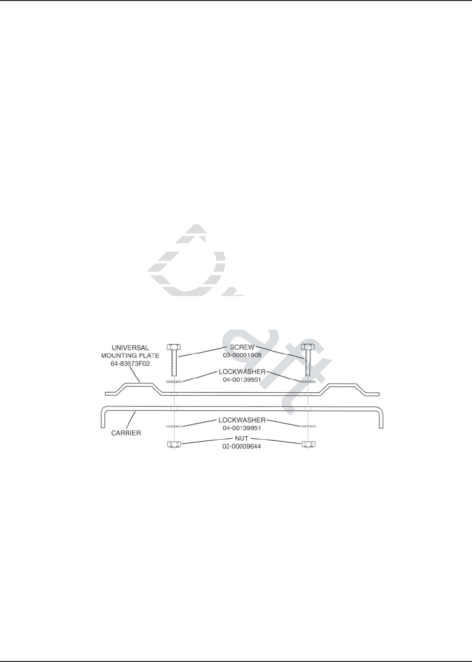
Figure 5-2. Universal Mounting Plate Installation (Part of Radio Enclosure Kit)
Follow the procedures below to mount the universal mounting plate to the motorcycle
(see Figure 5-2).
1. Determine the mounting position for the mounting plate.
2. Determine whether stainless steel spacers are required for clearance in mounting the plate.
3. Drill four 9/32-inch holes in the mounting plate and the corresponding motorcycle carrier or
chassis for mounting the plate.
4. Attach the universal mounting plate to the motorcycle using four machine screws, eight lock
washers, and four nuts. Tighten screws securely. The lock washers must cut through the
paint on the plate and motorcycle carrier or frame to ensure a good ground path.
Draf
versal versal
are met.are met.
nding path from thending path from
el lock washers must be
el lock washers mu
aint on the universal mountint on the univers
al contact with the undersidal contact with the u
MN003109A01_aa
Motorcycle Radio Installation Installing the Speaker and Control Head 5-7
5.4 Installing the Speaker and Control Head
NOTE: To disable the internal speaker of the O2 Control Head, please refer to Section 2.5.1: “Internal
Speaker Disassembly” .
The control head mounting location and configuration is determined largely by the make and model
of motorcycle. Two different mounting configurations are described below. One involves mounting
the speaker and control head together as a unit using the combination speaker/control-head bracket
(shown in Figure 5-4) supplied by Motorola. Alternately, the control head may be mounted by itself
using a smaller control-head bracket supplied by Motorola. In this case, the speaker is mounted
elsewhere. This section outlines installation procedures for each configuration mentioned above.
The customer (or installer) is in the best position to determine the most appropriate mounting
configuration for the control head and speaker based on the particular motorcycle on which the
equipment is to be mounted.
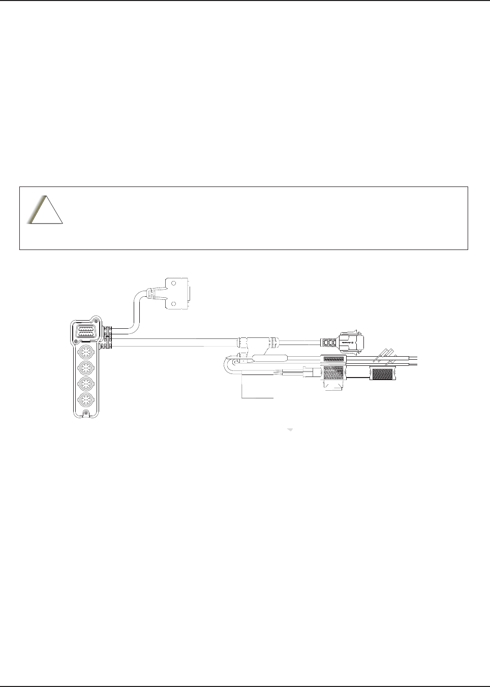
Figure 5-3. Motorcycle Control Head Cabling (3075217A01)
When determining its location, position the control head so that it is clearly visible and
within easy reach of the motorcycle operator.
!
C a u t i o n
Draft
ab
ab
D
raft
Draf
ra
ra
D
D
D
D
D
D
D
D
D
D
D
D
D
D
D
D
D
D
D
D
D
D
D
D
D
D
D
D
D
D
D
D
D
D
D
D
D
D
D
D
D
D
D
D
D
D
D
D
D
D
D
D
D
D
D
D
D
D
D
D
D
D
D
D
D
D
D
t
t
t
t
t
t
t
t
t
t
ft
ft
ft
f
ft
ft
ft
ft
ft
f
ft
ft
t
t
t
t
t
t
t
t
t
t
t
t
t
t
t
t
t
t
t
t
t
t
t
t
t
t
t
t
t
t
t
t
t
t
t
t
t
t
t
t
t
t
t
t
t
t
t
t
t
t
t
t
t
t
t
t
t
t
t
t
t
t
t
ft
t
t
t
t
t
t
ft
t
t
t
t
ft
t
t
t
ft
t
ft
t
t
ft
ft
t
ft
t
t
ft
t
t
ft
ft
t
t
t
ft
ft
t
t
ft
ft
t
t
t
t
t
ft
ft
ft
ft
ft
ft
ft
t
t
ft
ft
ft
ft
ft
ft
ft
ft
ft
f
f
ft
ft
ft
t
t
t
t
t
t
t
t
t
t
t
t
t
t
t
t
t
t
t
t
t
t
ft
t
t
t
t
t
t
ft
t
t
t
ft
t
t
t
t
ft
t
ft
t
t
ft
t
ft
t
f
aft
aft
af
t
ft
t
ft
t
t
t
ft
t
ft
t
t
t
ft
ft
t
ft
t
t
ft
ft
ft
ft
ft
f
ft
af
af
af
af
af
af
af
af
af
af
af
af
ft
ft
t
ft
ft
ft
ft
t
t
t
t
t
t
t
t
t
t
t
t
ft
ft
t
t
t
t
t
t
ft
ft
t
t
t
t
t
t
t
ft
ft
ft
ft
t
t
t
t
t
t
ft
t
t
t
t
t
ft
t
t
t
t
t
ft
af
ft
aft
aft
aft
aft
aft
aft
aft
ft
ft
t
t
t
t
t
aft
ft
ft
t
t
t
t
t
a
t
t
t
t
t
ft
t
t
t
t
t
ft
ft
t
t
t
t
t
aft
ft
ft
t
t
t
t
t
aft
t
t
t
t
ft
ft
t
t
t
t
ft
ft
ft
t
t
t
a
ft
ft
ft
t
t
t
aft
t
t
t
ft
t
t
t
ft
aft
ft
t
t
t
ft
ft
t
t
t
ft
ft
ft
t
t
ft
t
t
ft
ft
ft
ft
t
t
ft
ft
aft
ft
aft
ft
a
aft
aft
aft
aft
aft
aft
ra
a
a
af
ra
ra
ra
a
ra
a
ra
ra
ra
a
ra
ra
a
ra
ra
ra
a
ra
ra
a
ra
ra
ra
a
af
a
f
af
a
a
a
a
f
f
f
af
af
f
a
a
a
af
ra
ft
ft
a
a
a
a
a
a
a
a
af
ra
a
af
ra
af
ra
ra
af
af
af
af
af
af
ra
ra
a
ra
ra
ra
ra
ra
ra
ft
ft
ft
ft
ft
ft
ft
ft
ft
ft
ft
ft
t
t
ft
t
t
ft
ft
t
t
t
t
ft
ft
t
t
t
t
t
t
t
t
t
ft
ft
t
t
t
t
t
t
t
t
t
t
t
t
t
t
t
t
t
t
t
t
t
t
t
t
t
t
t
t
t
t
t
t
t
ft
t
af
af
a
a
a
ra
ra
a
a
a
ra
af
af
a
a
a
ra
af
af
af
af
af
af
ra
ra
ra
a
a
ra
af
ft
af
af
ft
ft
a
aft
MN003109A01_aa
5-8 Motorcycle Radio Installation Installing the Speaker and Control Head
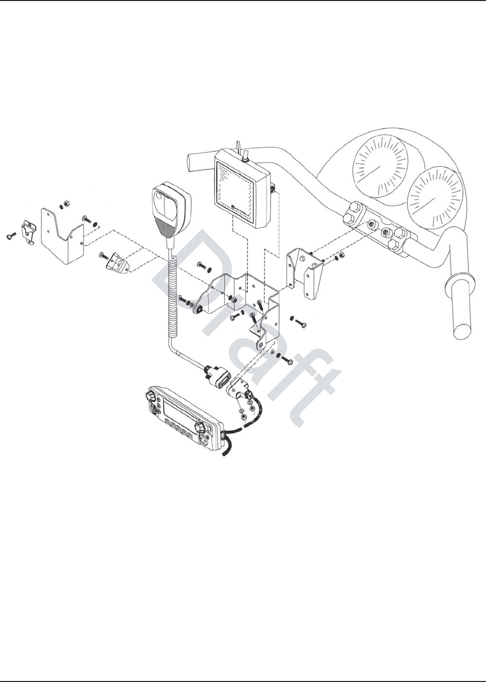
5.4.1 Handlebar Installation with Speaker and Control Head Mounted Together
Figure 5-4 illustrates the combination speaker/control head bracket. This combination bracket is
used only when the control head and speaker are to be mounted as a unit. Also illustrated in
Figure 5-4 is a handlebar-mounting bracket which may be required if the combination speaker/
control-head bracket cannot be easily mounted to the motorcycle. In this case the
handlebar-mounting bracket is mounted to the motorcycle, and the combination bracket is then
mounted to the handlebar-mounting bracket.
Figure 5-4. Handlebar Installation with Speaker and Control Head Mounted Together

MN003109A01_aa
Motorcycle Radio Installation Installing the Speaker and Control Head 5-9
Provision has been made on the combination speaker/control-head bracket for mounting the
microphone hang-up clip. If that mounting is desired, the hang-up clip must be attached to the
bracket before installing the control head and speaker. See Section 5.6: “Installing the Microphone
Hang-Up Clip” for the hang-up clip procedure. Install the speaker and control head as described
below.
1. Determine the location where the speaker/control head is to be mounted. Consider how the
speaker/control-head bracket may be mounted, and whether or not a handlebar-mounting
bracket is needed. Take care to select a location that is not only mechanically convenient, but
is located for ease of operation.
NOTE: The angle at which the handlebar-mounting bracket or the speaker/control-head bracket is
mounted to the motorcycle determines the firing angle of the speaker.
2. If the handlebar-mounting bracket is needed, install it first.
3. Mount the speaker/control-head bracket, either directly to the motorcycle, or, if used, to the
handlebar-mounting bracket, using four stainless-steel machine screws, lock washers, and
nuts.
4. Mount the 9-pin D-connector end of the motorcycle control-head cable to the speaker/control
head bracket, using two machine screws, flat washers, and nuts. (Cable routing directions
appear later in this section.)
5. Mount the speaker on the speaker/control-head bracket, using two machine screws and lock
washers. Torque these screws to 20 in-lbs.
6. Attach the control-head cable to the control head and tighten the locking screws on the
connector. This connection must be made before you mount the control head in the bracket.
(Cable routing directions appear later in this section.)
7. Mount the control head to the bracket, using two machine screws, lock washers, and flat
washers.
8. Adjust the control head viewing angle by loosening its mounting screws and rotating the
control head to the desired angle. Then, retighten screws to 20 in-lbs torque. This concludes
the speaker/control-head installation.
5.4.2 Fuel Tank Console Installation with Speaker and Control Head Mounted
Together
Some motorcycles provide a console for mounting radio equipment. This console is attached to the
top of the fuel tank. With the use of a mounting bracket, screws, nuts, and lock washers, the
combination speaker/control-head bracket can be mounted to this console. Figure 5-5 illustrates this
type of mounting.
The console attachment screws must be removed, and the console must be lifted slightly from the
fuel tank to gain access in order to attach mounting hardware, and to route cables later.
In this installation, the microphone (mic), mic hang-up bracket, and mic extension bracket will
interfere with handlebar travel.
Installation using this method is the same as in Section 5.4.1: “Handlebar Installation with Speaker
and Control Head Mounted Together” .
Draft
tor
to
o machino machi
ection.) ection
er on the speaer on
ker/coke
e these
e the
screws to 20 in-l to
-head cable to the contro-head cable to the
l
nection must be made beection must be ma
fo
ns appp
ear later in this sectiear later in th
the bracket, using he bracket, using
two mactw
angle by longle by lo
osening its mou
osening its mo
hen, retighten screws to 2
en, retighten screws t
aker anker
MN003109A01_aa
5-10 Motorcycle Radio Installation Installing the Speaker and Control Head
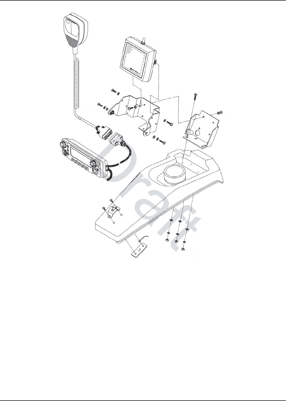
Figure 5-5. Fuel Tank Console Installation with Speaker and Control Head Mounted Together
f

MN003109A01_aa
Motorcycle Radio Installation Installing the Speaker and Control Head 5-11
5.4.3 Handlebar Installation with Speaker and Control Head Mounted Separately
It may be necessary to use the smaller control head bracket (part number 07-80127N02) and mount
the speaker and microphone hang-up clip in another location on the motorcycle.
Before installing the control head using the bracket described above, the control-head end of the
control-head cable should be temporarily fastened to the control head, and the control head fastened
to its bracket. Motorola-supplied spacers and the mic-cable bracket are required to mount the control
head to the handlebar. This mic-cable bracket has holes to mount the microphone-cable connector.
Follow these procedures when mounting the smaller control-head bracket:
1. Determine the location at which the control head is to be mounted. Take care to choose a
location that is not only mechanically convenient, but is located for ease of operation.
2. Securely mount the Motorola-supplied spacers, mic-cable bracket, and small control-head
bracket to the handlebars.
3. Mount the 9-pin D-connector end of the motorcycle control-head cable to the mic-cable
bracket, using two machine screws, flat washers, and nuts. (Cable routing directions appear
later in this section.)
4. Attach the control-head end of the cable to the control head and tighten the locking screws on
the connector.
5. Mount the control head to the small control-head bracket, at the proper viewing angle, using
two wing screws. Tighten firmly. This concludes the control-head installation.
end end
ofof
head to the small chead to the sma
ws. Tighten firmly. This
s. Tighten firmly. T
co
MN003109A01_aa
5-12 Motorcycle Radio Installation Installing the Speaker and Control Head
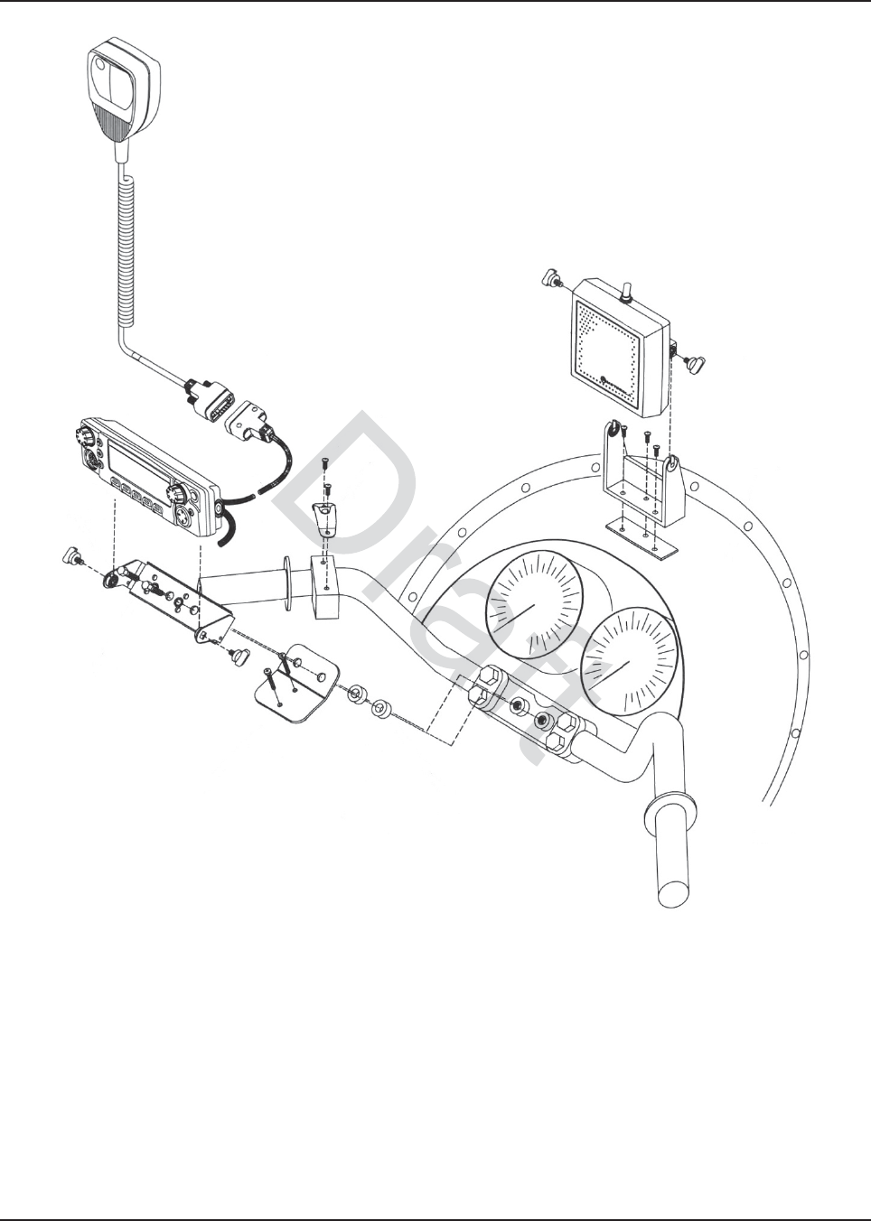
Figure 5-6. Handlebar Installation with Speaker and Control Head Mounted Separately
5.4.4 Fuel Tank Console Installation with Speaker and Control Head Mounted
Separately
The control head may be mounted to the fuel tank console using the smaller control-head bracket
and spacers/hardware. In this configuration, the microphone cable connector may be attached
directly to the console, eliminating the need for a custom bracket.
MN003109A01_aa
Motorcycle Radio Installation Installing the Speaker and Control Head 5-13
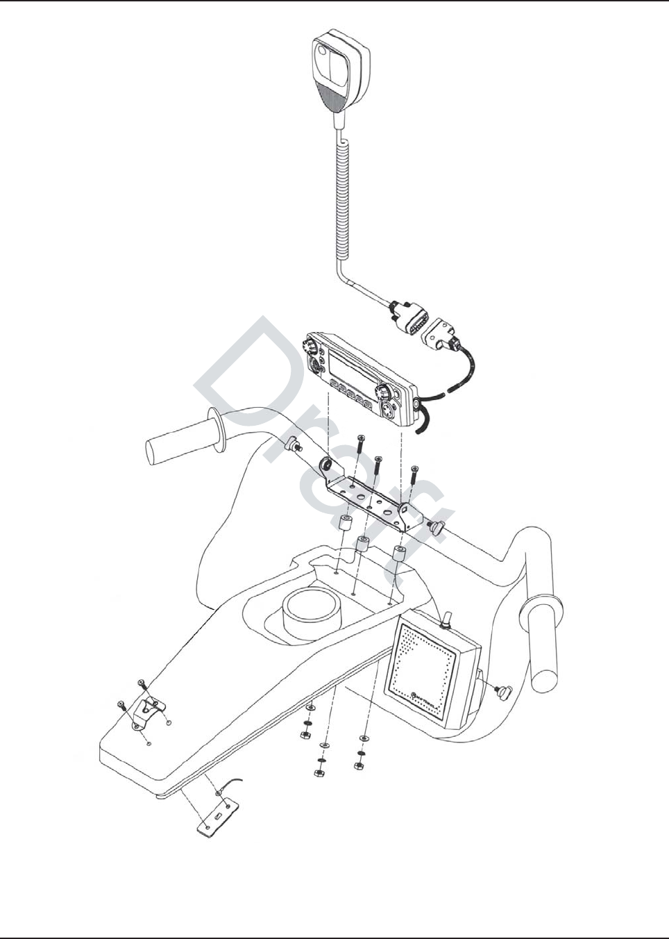
Figure 5-7. Fuel Tank Console Installation with Speaker and Control Head Mounted Separately
Installation is the same as detailed in Section 5.4.2: “Fuel Tank Console Installation with Speaker and
Control Head Mounted Together” and Section 5.4.3: “Handlebar Installation with Speaker and
Control Head Mounted Separately” .

MN003109A01_aa
5-14 Motorcycle Radio Installation Installing the Speaker
5.5 Installing the Speaker
NOTE: To disable the internal speaker of the O2 Control Head, please refer to Section 2.5.1: “Internal
Speaker Disassembly” .
Use the following procedure when the speaker is mounted separate from the control head. The
speaker bracket supplied with the speaker may be used alone if a suitable location can be found, or
if necessary, a customer-supplied bracket may be fabricated for mounting the speaker.
1. Determine the location in which the speaker is to be mounted and whether there is a
requirement for a customer-supplied bracket.
2. Fabricate a bracket if required. Use the Motorola-supplied speaker bracket as a template for
drilling mounting holes. Also drill holes in the fabricated bracket for mounting to the
motorcycle.
3. Mount the fabricated bracket to the motorcycle chassis.
4. Mount the Motorola-supplied bracket to the fabricated bracket using two machine screws, flat
washers, lock washers, and nuts.
5. Mount the speaker to the speaker bracket using two wing screws. Directions for speaker
cable routing appear later in this section. Speaker mounting is now complete.
5.6 Installing the Microphone Hang-Up Clip
Install the hang-up clip either on the supplied microphone extension bracket or on the side of the
speaker/control head bracket. Both methods are shown in Figure 5-4. Determine the mounting
location and install as described in the following paragraphs.
NOTE: Wherever the hang-up clip is mounted, it must be DC grounded for proper operation. After
mounting the clip, be sure there is electrical continuity between the clip and the motorcycle
chassis.
5.6.1 Extension Bracket Mounting
Using this method, you can mount the clip so that it faces the operator.
1. Attach the bracket to the speaker/control-head bracket using two machine screws, four lock
washers, and two nuts as shown in Figure 5-4.
2. Torque nuts to 20 in-lbs torque.
3. Fasten the hang-up clip to the extension bracket using two machine screws, lock washers,
and nuts as shown in Figure 5-4.
4. Torque nuts to 20 in-lbs torque.
5.6.2 Speaker/Control Head Bracket Side Mounting
Attach the hang-up clip to the left side of the speaker/control-head bracket using two machine
screws, lock washers, and nuts as shown in Figure 5-4. Torque nuts to 20 in-lbs. torque.
Draft
ea
in this sin this
ophone Hangophone Ha
ther on the supplied mi
ther on the supplie
cro
ket. Both methods are showet. Both methods a
ed in the following paragraed in the following p
p is mounted, it must be Dmounted, it mus
ere is electrical ere is electric
continuity bcon
it faces the operat faces the opera
bracket uacke
MN003109A01_aa
Motorcycle Radio Installation Installing Antenna Base, Cables and Multiplexer 5-15
5.6.3 Other Hang-Up Clip Mounting
To mount the microphone hang-up clip in another location, a customer-supplied bracket may be
used. Suggested locations include the handlebars, fuel-tank console, or any location which provides
easy access to the microphone without blocking controls and indicators and without interfering with
motorcycle handling. See Figure 5-5, Figure 5-6, and Figure 5-7 for alternative microphone hang-up
clip mounting methods.
1. Fabricate a bracket, then secure it to the motorcycle.
2. Use two machine screws, lock washers, and nuts to secure the hang-up clip to the
customer-supplied bracket. Ensure that the microphone clip is DC grounded to the
motorcycle chassis (a grounding lug and strap are provided in the hang-up clip kit for this
purpose) – this is essential for proper radio operation.
5.7 Installing Antenna Base, Cables and Multiplexer
NOTE: Antenna hole placement and cable routing in 700/800, VHF and UHF antenna manuals are
not applicable for the APX Series.
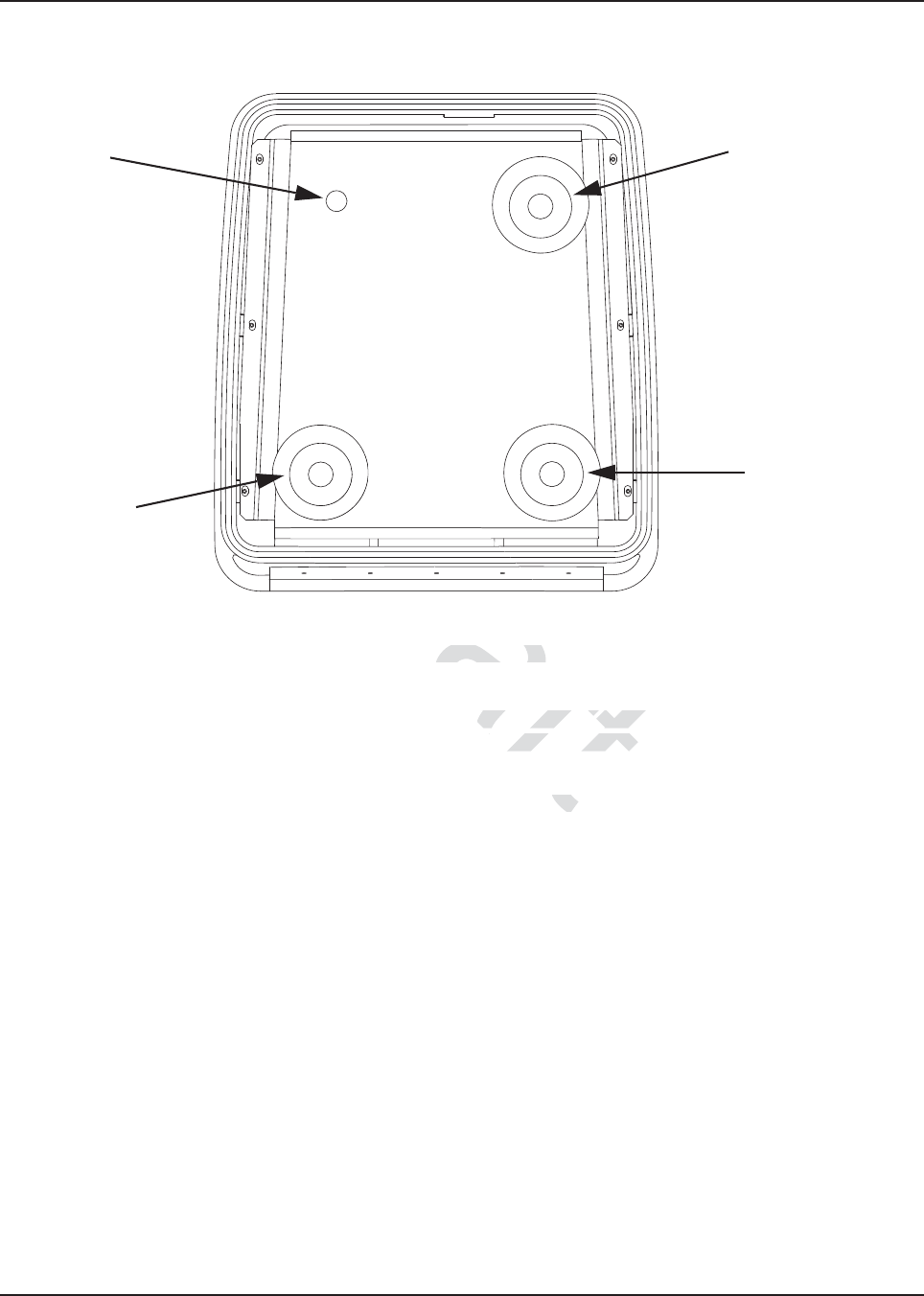
The GPS antenna assembly must be done after the removal of the metal liner but before
reinstalling the APX Series liner.
Figure 5-8. Antenna Band Identification
1. Open the top cover of the weather-resistant enclosure.
2. Uninstall the metal liner that is shipped attached to the weather-resistant enclosure. This liner
has one depressed area at the top of the enclosure liner just toward the rear of the enclosure.
This metal liner is not used with APX Series products.
3. Place the metal liner with two round, depressed areas toward the enclosure hinge and 1 inch
hole near the front of the housing, inside the top cover, and align the six slots in the metal
liner with the screw holes in the top housing.
4. The metal liner of the enclosure’s top cover acts as a ground plane for the antenna.
5. Locate the two round, depressed areas about 3 inches in diameter in the metal liner near the
enclosure hinge. Referring to Figure 5-9, these areas are either VHF or UHF depending on
the antenna port locations. For the GPS antenna, use the 1 inch hole near the front of the
housing near the lock.
GPS
LMR all-band Port
Wi-Fi
Draft
embly membly m
X Series liner.X Series liner.
Draft
raft
raft
Dra
D
Dr
r
ra
Dra
a
ra
ra
a
a
f
a
f
f
ft
f
f
f
ft
ft
ft
aft
a
ft
f
f
f
aft
aft
aft
aft
ft
f
f
f
f
aft
aft
aft
ft
ft
ft
a
a
ft
ft
f
ft
ft
ft
ft
ft
ft
ft
f
ft
f
f
ft
f
f
ft
f
f
f
f
f
f
f
aft
aft
aft
aft
a
ft
ft
ft
t
ft
t
ft
t
ft
t
ft
ft
ft
ft
ft
f
f
f
f
f
f
f
f
f
f
f
f
f
f
f
a
ft
t
t
t
t
t
t
t
ft
ft
ft
ra
r
f
ra
r
f
ra
r
r
ra
ra
ft
Dra
Dra
Dr
Dr
Dr
a
aft
ft
ft
ft
ft
af
af
aft
f
ft
aft
aft
aft
ft
ft
ft
ft
ft
ft
ft
ft
ft
ft
ft
ft
ft
ft
ft
ft
ft
ft
ft
ft
ft
ft
ft
ft
ft
ft
t
ft
t
t
ft
ft
ft
ft
t
ft
ft
t
ft
t
t
ft
t
ft
t
ft
ft
ft
ft
t
a
a
a
a
a
a
a
a
a
r
af
af
ra
af
raf
a
ra
a
a
a
a
ra
ra
a
a
a
r
ra
r
ra
r
r
ra
ra
r
ra
r
ra
r
r
ra
r
ra
r
r
ra
ra
ra
r
ra
ra
ra
ra
ra
ra
ra
ra
ra
ra
ra
ft
ft
ft
ft
t
ft
ft
a
f
a
aft
aft
a
f
a
a
a
a
ft
ft
ft
t
ra
ra
a
a
f
ra
ra
r
a
ra
ra
r
f
f
f
f
f
f
ft
ft
ft
ft
ft
ft
ft
ft
ft
ft
ft
ft
ft
ft
t
ft
ft
ft
ft
t
t
t
t
t
ft
ft
ft
ft
f
ft
f
aft
f
f
aft
f
aft
f
a
f
f
ft
f
f
f
ft
ft
ft
ft
f
f
f
f
f
f
f
ft
f
f
f
f
ft
ft
ft
ft
ft
ft
ft
ft
ft
ft
f
ra
ra
ra
ra
ra
ra
ra
ra
a
a
a
a
a
a
a
a
f
f
f
f
f
aft
f
aft
aft
aft
f
f
aft
aft
aft
a
a
Dr
Dr
Dr
aft
ft
ft
ft
af
f
aft
aft
aft
aft
ft
ft
a
aft
f
f
f
aft
aft
f
aft
f
r
r
ra
ra
ra
a
ra
a
a
a
a
r
ra
a
a
r
ra
a
a
a
a
ra
ra
ra
a
ra
r
r
ra
ra
r
a
r
r
r
ra
a
a
r
ra
ra
r
r
ra
a
a
a
ra
ra
a
a
ra
a
ra
a
ra
a
ra
ra
ra
ra
ra
ra
ra
a
ra
ra
ra
ra
a
a
a
ra
ra
a
a
a
a
r
a
ra
a
a
ra
ra
a
a
ra
ra
a
ra
a
ra
a
r
a
a
ra
ra
r
a
a
ra
a
a
r
ra
r
ra
a
ra
a
ra
ra
a
a
ra
a
ra
ra
a
a
r
a
a
ra
a
r
ra
ra
r
ra
a
a
a
ra
a
ra
a
a
a
a
a
a
a
a
a
a
a
a
a
ra
ra
ra
ra
ra
ra
r
ra
ra
ra
ra
ra
ra
r
ra
ra
ra
a
ra
a
a
ra
ra
a
a
ra
a
a
ra
a
a
ra
a
r
a
a
a
ra
ra
a
a
a
a
a
a
a
a
ra
ra
a
a
a
a
a
a
a
a
a
a
a
a
a
a
a
a
a
a
a
a
a
a
a
a
a
a
a
a
a
a
a
a
a
a
a
a
a
a
a
a
a
a
a
a
a
a
a
a
a
a
a
a
a
a
a
a
a
a
a
a
a
a
a
a
a
a
a
a
a
a
a
a
a
a
a
a
aft
ft
ft
ft
ft
ft
MN003109A01_aa
5-16 Motorcycle Radio Installation Installing Antenna Base, Cables and Multiplexer
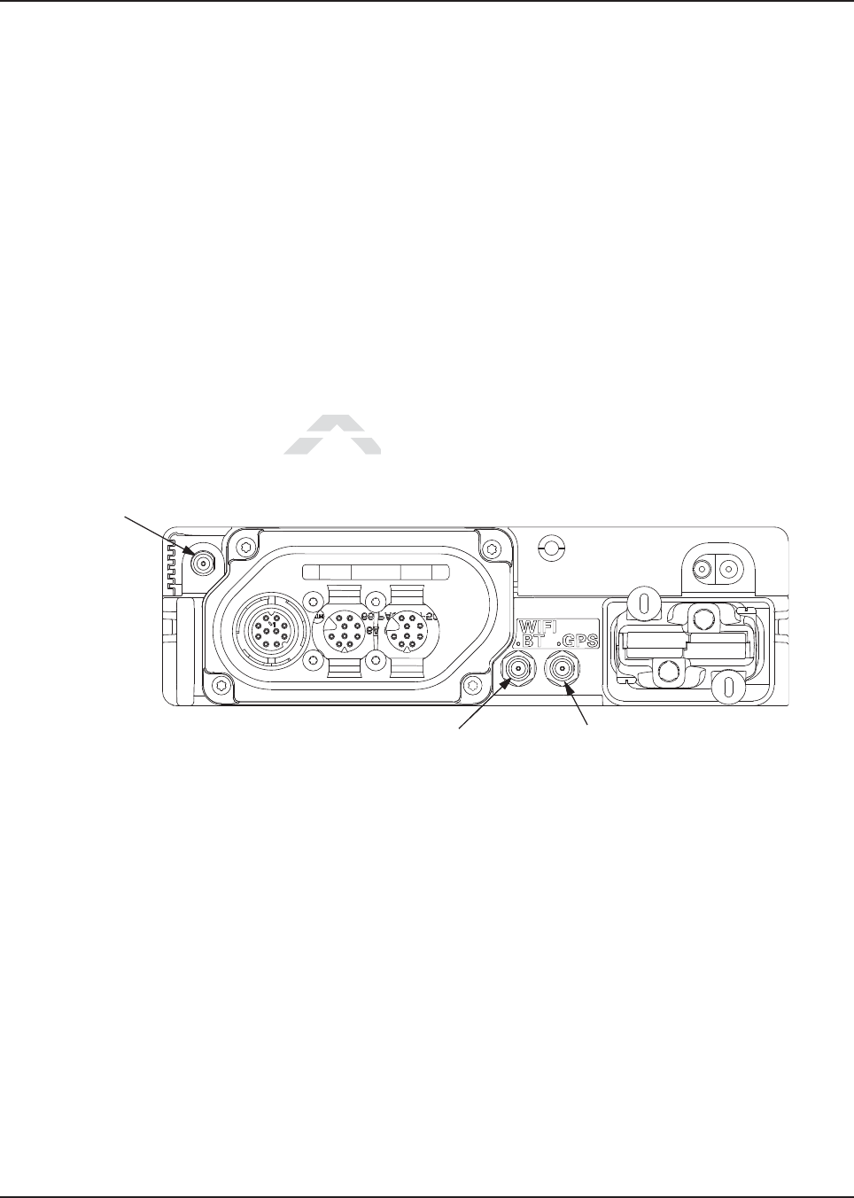
Figure 5-9. Antenna Port Locations
6. These holes in the metal liner is used as a template to mark the position of the hole(s) to be
drilled at the top cover. Follow the below guidelines for the various options.
7. Remove the metal liner from the top cover.
8. For LMR all-band antenna, use the Motorola RPX-4378A Hole-Cutting Saw or equivalent,
and carefully drill a 3/4-inch hole at the marked location from the inside of the cover until the
saw bottoms out. For the GPS/WiFi carefully drill a 1 1/16-inch hole at the marked location
from the inside of the cover until the saw bottoms out. The saw should clean a neat circle to
assure good contact between the antenna and the housing.
IMPORTANT: For proper seating of the antennas, deburr and scrape any foreign
matter from both sides of the hole, being careful not to mar the
finish of the shell.
9. Clean the mounting surface around the hole to remove dirt and wax.
10. Refer to the Motorcycle GPS Instruction Manual for further installation instruction for the
GPS. GPS must be mounted before the APX metal liner is installed.
11. Reinstall the APX metal liner with the cable clamps provided in the weather-resistant housing.
12. Attach the 700/800, VHF or UHF antenna base per Antenna Installation Manual.
IMPORTANT: Antenna Placement and Cable Routing in the Antenna Installation
Manual is not applicable for the APX series.
Top Cover for APX Radios
700/800
Antenna
UHF
Antenna
GPS/Wi-Fi
VHF
Antenna
Draft
. Antenna Port Locationstenna Port Locations
as a template to mark the
a template to mark t
guidelines for the vaguidelines for the v
X-437X-43
Dr
Dr
Dr
Dr
Dr
Dr
Dr
D
D
D
D
D
D
D
D
D
Dr
D
D
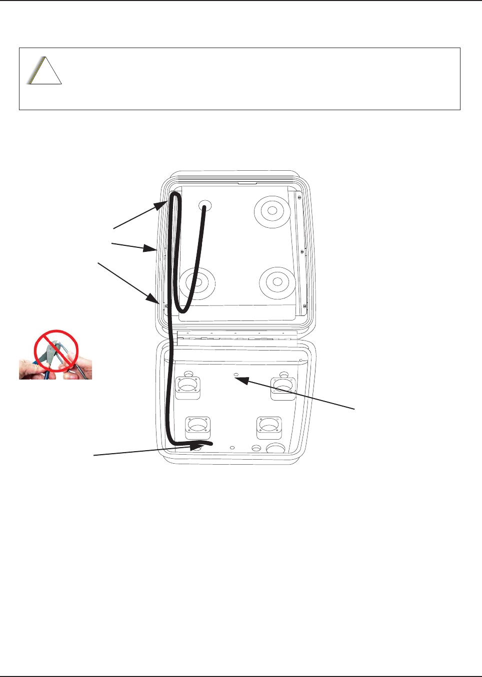
MN003109A01_aa
Motorcycle Radio Installation Installing Antenna Base, Cables and Multiplexer 5-17
13. Route the coaxial cable for the 700/800, VHF or UHF antenna(s) through the cable clamps
per Figure 5-11 for VHF hole, Figure 5-12 for 700/800 hole and Figure 5-13 for UHF hole.
14. After routing cable, allow enough of the cable to reach the radio’s antenna connector and cut
off any excess length of the cable.
15. Install the connector per Antenna Installation Manual.
Figure 5-10. Routing the GPS/Wi-Fi Cable
Be sure to observe the correct routing of the antenna cable. Failure to do so can damage the
cable.
!
C a u t i o n
Cable routes underneath
radio mounting plate and
connects to multiplexer
mounted underneath radio
on the radio mounting plate
Cable Clamps need to
be included and
routing to be through
cable clamps
GPS/Wi-Fi cables
connect to radio
directly
NOTE: Do not cut
the antenna cable
aft
ft
ft
ft
ft
ft
ft
ft
ft
t
t
ft
Draft
Draft
D
D
D
D
ra
raf
ra
ra
ra
D
D
D
ra
ra
ra
D
D
D
D
D
D
ra
D
D
ra
a
f
Dra
D
D
D
D
D
D
D
D
D
D
D
f
Dr
Dr
D
Dr
ft
r
ra
ra
ra
af
af
af
f
r
ra
ra
ra
raf
af
af
af
f
f
f
f
raft
ft
aft
aft
a
aft
aft
aft
ft
aft
ft
ft
ft
aft
ft
aft
ft
Dr
af
af
af
aft
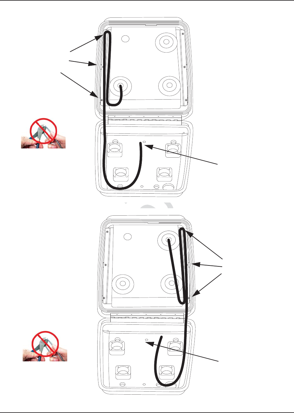
MN003109A01_aa
5-18 Motorcycle Radio Installation Installing Antenna Base, Cables and Multiplexer
Figure 5-11. Routing the VHF Antenna Cable
Figure 5-12. Routing the 700/800 Antenna Cable
Cable Clamps need to
be included and
routing to be through
cable clamps
Cable routes underneath
radio mounting plate and
connects to multiplexer
mounted underneath radio
on the radio mounting plate
NOTE: Do not cut
the antenna cable
Cable Clamps need to be
included and routing to be
through cable clamps
Cable routes underneath
radio mounting plate and
connects to multiplexer
mounted underneath radio
on the radio mounting plate
NOTE: Do not cut
the antenna cable
Dra
Routing the VHF Antenna CRouting the VHF An
Dra
Dra
ra
Dra
Dr
D
D
D
D
D
D
D
r
r
Dr
Dr
D
D
D
D
D
D
Dr
r
r
Dr
Dr
D
Dr
raft
aft
a
af
a
a
af
af
ft
ft
ft
ft
ft
a
ft
ft
aft
ft
aft
ft
aft
ft
aft
af
aft
a
aft
aft
aft
aft
af
aft
aft
ft
ft
ft
ft
ft
ft
ft
ft
ft
ft
ft
ft
ft
ft
ft
ft
aft
aft
ft
aft
aft
ft
ft
ft
ft
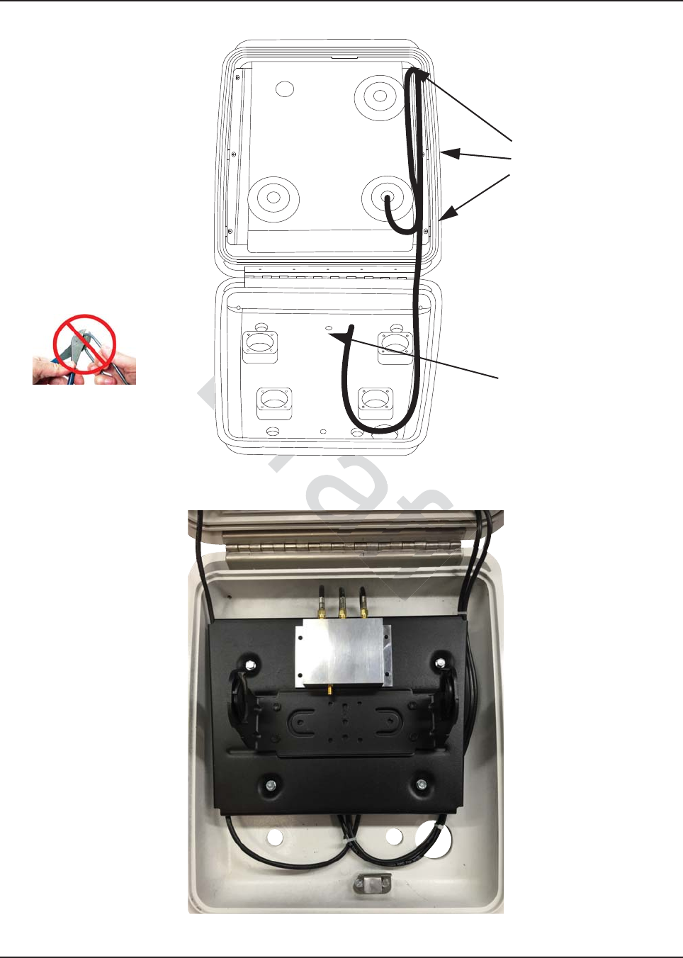
MN003109A01_aa
Motorcycle Radio Installation Installing Antenna Base, Cables and Multiplexer 5-19
Figure 5-13. Routing the UHF Antenna Cable
Figure 5-14. Multiplexer and Trunnion Mounting
Cable Clamps need to be
included and routing to be
through cable clamps
Cable routes underneath
radio mounting plate and
connects to multiplexer
mounted underneath radio
on the radio mounting plate
NOTE: Do not cut
the antenna cable
Routing the UHF Antenn Routing the UHF
Dra
Dra
ra
Dra
Dr
D
D
D
D
D
D
D
D
D
D
Dr
D
D
D
D
D
D
Dr
Dr
Dr
D
r
aft
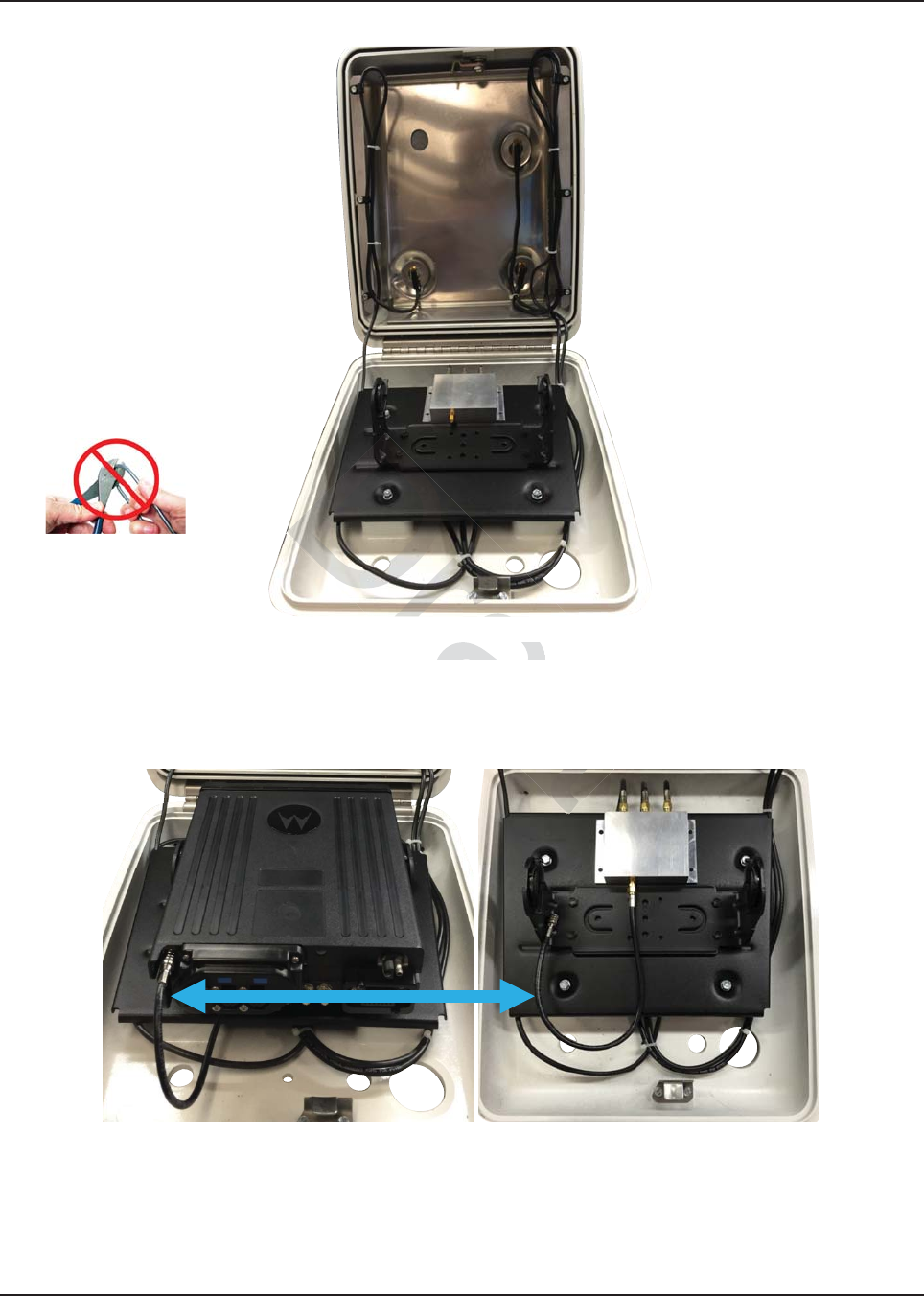
MN003109A01_aa
5-20 Motorcycle Radio Installation Installing Antenna Base, Cables and Multiplexer
Figure 5-15. Cable Routing
Figure 5-16. Cable from Radio to Multiplexer
NOTE: Radio has to be mounted with the TIB facing the front of the enclosure
NOTE: Do not cut
the antenna cable
raft
e 5-15. Cable Routing5. Cable Rou
Dra
ft
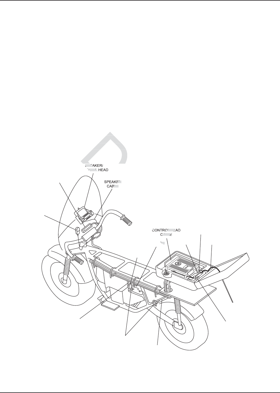
MN003109A01_aa
Motorcycle Radio Installation Installing the Antenna 5-21
5.8 Installing the Antenna
IMPORTANT: Antenna Placement and Cable Routing as described inside the
Antenna Installation Manual is not applicable for the APX radio
series. Refer to information listed below.
• Connect the appropriate antenna connectors to the antenna receptacles on the radio. Tighten
the coupling until fully engaged.
5.9 Cable Routing
Five cables must be installed to interconnect the components of the radio system as shown in
Figure 5-17. The antenna cable is routed away from the other cables inside the enclosure’s hinged
cover (see Section 5.7). The four remaining cables, routed along the motorcycle frame, are
described in the following paragraphs.
NOTE: Antenna Hole Placement and Cable Routing information in the Antenna Installation Manual
is not applicable to the APX series.
Removal of the fuel tank and seat from the motorcycle will facilitate routing the cables along
the frame. Motorcycles with consoles attached to fuel tanks require routing cables between
console and fuel tank. In this case the tank is not removed.
Figure 5-17. Cable Routing
1. Speaker Cable – runs from the speaker to the accessory-cable connector inside the
weather-resistant enclosure.
CONTROL HEAD
CABLE
SPEAKER/
CONTROL HEAD
SPEAKER
CABLE
MICROPHONE
IGNITION
CABLE
CHASSIS GROUND
FUSED POWER
CABLE
SPEAKER
CABLE
ANTENNA
CABLE
ACCESSORY
CABLE
POWER
CABLE
CONTROL HEAD
CABLE
BATTERY
FUSE
BLOCK
and
an
es with cones with co
nk. In this nk. In this
casecas
Draft
SPEA
TROL
ER
BLE
CONTROL HEA
CABLE
RY
t
r
D

MN003109A01_aa
5-22 Motorcycle Radio Installation Cable Routing
2. Control Cable – runs from the rear of the control head to the front of the transceiver inside
the enclosure.
3. Ignition Sense (Red) Wire Portion of Accessory Cable – runs from the ignition sense fuse
terminal of the fuse box to the rear area inside the enclosure. The lug for attaching the ignition
sense wire is contained on the accessory cable.
4. Power Cable – The red, unterminated end runs from the positive terminal of the battery to
the power connector that plugs in the rear of the transceiver. Lugs for attaching the red and
black leads are contained in the motorcycle power-cable kit. The black, unterminated end
runs from a suitable motorcycle chassis ground to the power connector. DO NOT connect the
black lead directly to the negative battery post.
You may route the cables in any order. As you route each cable, temporarily fasten it at both ends.
When all cables have been run, permanently fasten the cables with appropriate cable tie wraps.
Observe the following during routing and hook-up:
1. Route the cables so that none interfere with motorcycle operation.
2. Fasten the cables with supplied nylon tie wraps. The wraps should be firmly installed at
frequent intervals along the cable length in such a manner that motorcycle vibration will not
cause metal fatigue and subsequent breakage of the cable wires.
3. Take care to position cables away from parts of the motorcycle that get hot.
Bundle excess cable length inside the weather-resistant enclosure as discussed later in Section
5.11: “Transceiver, Cabling and Multiplexer Installation” .
The fifth cable is the microphone with coiled cord. Plug the 9-pin D-connector end of the coiled cord
into its mating connector, which was attached near the control head discussed in an earlier
paragraph. Tighten the coiled-cord-retention screws. Insert the S-hook strain relief (terminated to the
coiled cord) into the hole in the mounting bracket. Slide the microphone into the microphone hang-up
bracket.
Draft
ubsequubsequ
n cables away fromn cables away fro
gth inside the weather-
gth inside the weat
res
anan
d Multiplexer Installatiod Multiplexer Ins
ne with coiled cord. e with coiled cord.
Plug th
as attached near the contattached near th
etention screws. Intention screws. In
sert the s
g bracket. Slide the micropracket. Slide the microp
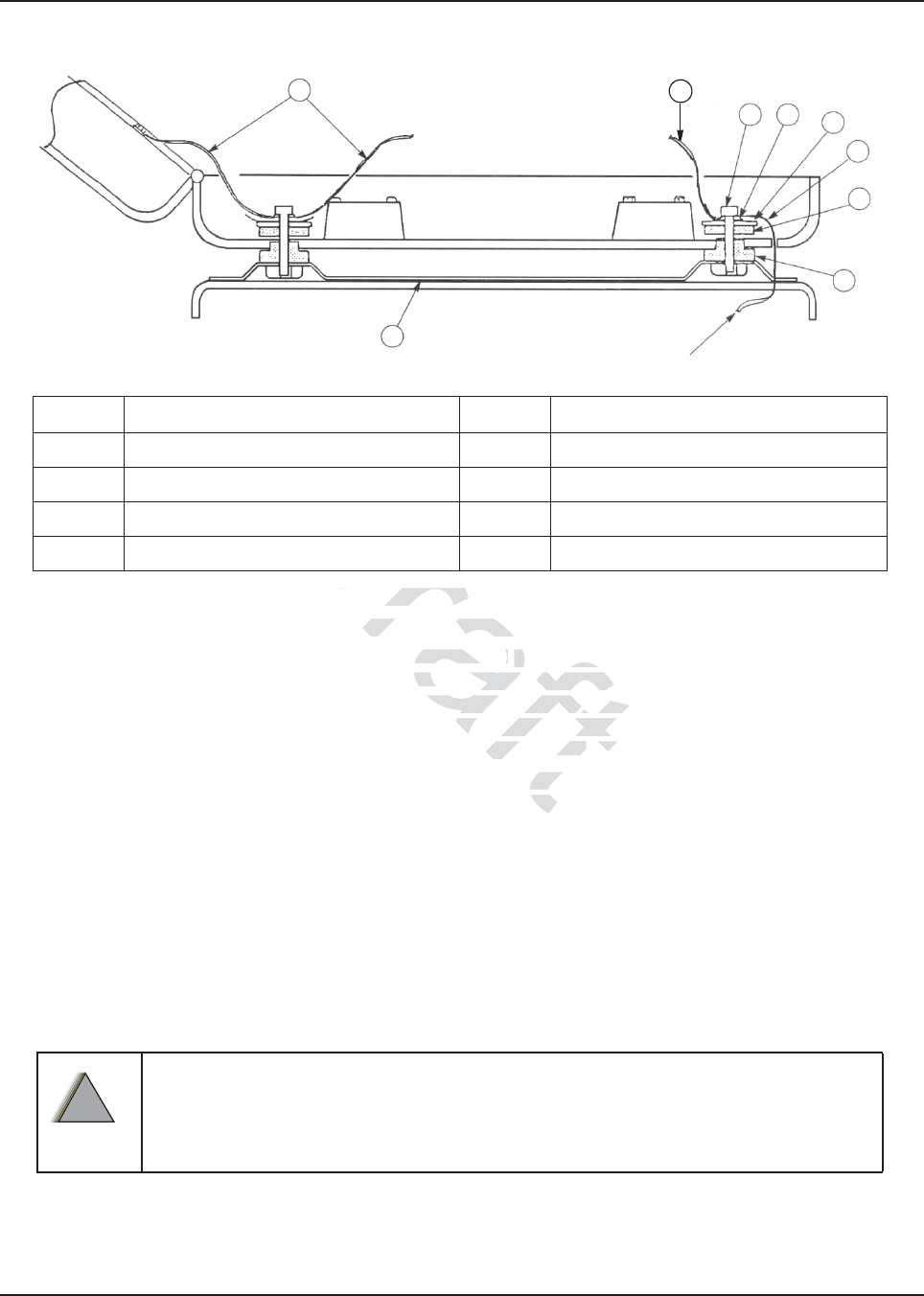
MN003109A01_aa
Motorcycle Radio Installation Installing the Weather-Resistant Enclosure 5-23
5.10 Installing the Weather-Resistant Enclosure
Figure 5-18. Weather-Resistant Enclosure Installation
1. Remove the radio-mounting plate by removing four screws, lock washers, and flat washers.
2. The weather-resistant enclosure is mounted to the universal mounting plate using shock
mounts. Assemble the shock-mount components exactly as shown in Figure 5-18. Be sure to
install ground straps between the shock-mount and the transceiver trunnion mount, and
install one 7-1/2-inch ground strap between the right rear mount and the enclosure lid’s
antenna ground plane 0 (shown in Figure 5-18 and in Figure 5-20).
3. The order of assembly is important to ensure proper shock mount operation. All components
are supplied with the mounting kit. The five 7- 1/2-inch straps are used on the rear and front
shock mounts – four from shock mount to trunnion, and one from the shock mount to the lid’s
antenna ground plane.
NOTE: Grounding through the power-supply cable is NOT sufficient. Whether the radio transceiver
is mounted to a carrier or the chassis itself, the transceiver MUST be properly grounded to
the motorcycle chassis. The ground strap supplied with the installation kit may have to be
used to ensure a good RF ground path from the radio transceiver to the motorcycle chassis.
4. Install the 3-foot ground strap on one of the front shock mounts. Route it through the cable-
routing hole and connect the other end to the motorcycle frame (see Figure 5-18).
DO NOT connect the ground strap directly to the negative battery post.
7
1
7
23 4
8
5
6
TO MOTORCYCLE
CHASSIS GROUND
Item No. Description Item No. Description
1 Universal Mounting Plate 5 Flat Rubber Washer
2 Machine Screw 6 Shouldered Rubber Washer
3 Lockwasher 7 7-1/2-inch Ground Strap
4 Flat Washer 8 Ground Strap
!
W A R N I N G
!
Draft
8. Weather-Resistant Enc Weather-Resis
ng plate by removing g plate by removin
four
sure is mounted is mounted
to the univto the univ
ount unt
components exactly amponents exactly
shock-mount and the trans
shock-mount and the tra
etween the right rear mo
tween the right rear
re 5-185-18
and in d in
FiguFig
e proper sprope
1/2-1/2-
in
r
D
D
D
Dr

MN003109A01_aa
5-24 Motorcycle Radio Installation Transceiver, Cabling and Multiplexer Installation
5. The diagram of the shock mount is shown loosely assembled. After the hex screws are
tightened, the rubber washers are compressed to fasten the weather- resistant enclosure
securely to the universal mounting plate.
6. Figure 5-20 is an exploded view of the enclosure; it shows details that will help to understand
how the enclosure is mounted. After the enclosure is completely mounted, check for proper
ground connection–continuity between the antenna ground plane and the motorcycle frame.
5.11 Transceiver, Cabling and Multiplexer Installation
After the weather-resistant enclosure has been installed, the radio chassis (transceiver) is installed in
the enclosure and then appropriate cables are connected. However, before the transceiver can be
installed, the cabling must be properly positioned in the enclosure.
5.11.1 Installing Cabling in the Enclosure
Position the cabling in the weather-resistant enclosure as follows:
1. Run the speaker, power, control-head, and ignition sense cables into the enclosure.
2. Lay the excess cable length between the radio mounting bosses in an S configuration as
shown in Figure 5-19. Do not coil any excess cable. Use the supplied tie wraps to bundle
cable as shown.
NOTE: If the extra cable length is not sufficient to match the illustrated cable routing, then match the
illustration as closely as possible.
3. Connect the speaker cable to the accessory cable connector.
NOTE: The accessory-cable emergency connector is shipped with a shorting plug installed. The
headset connector is also shipped with a shorting plug installed. The plugs must remain in if
an emergency switch and/or headset is not used. If an emergency switch and/or headset is
used, remove the shorting plug(s) and discard.
4. Install the mounting plate in position on top of the cables installed above. Take care not to
damage or pinch the cables when securing the mounting plate in position.
NOTE: At this point, the control-head cable plug should be located at the forward end of the
enclosure, and the power-cable, speaker-cable, and accessory-cable plugs should be located
at the rear of the enclosure.
be
be
not coil not coil
ength is not ength
sufficient fici
sely as possible.
sely as possible.
cable to cable to
the accessory cabthe accesso
ergency connector is shippncy connector
hipped with a shorting ipped with a shortin
plug
eadset is not used.set is not used
If an emn em
and discard.and discard.
n top of the cables installe
op of the cables inst
ng the mounting platthe mounting pla
uld be locatbe lo
and aand
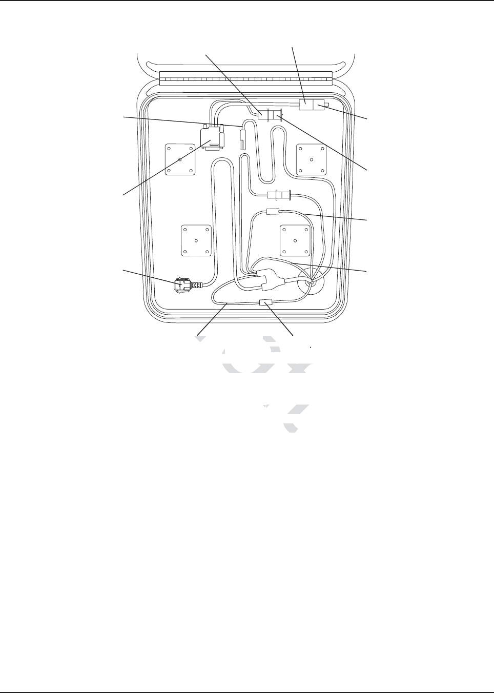
MN003109A01_aa
Motorcycle Radio Installation Transceiver, Cabling and Multiplexer Installation 5-25
Figure 5-19. Installing Cables
5.11.2 Installing the Transceiver
Install the transceiver in the weather-resistant enclosure as follows (see Figure 5-20).
NOTE: For new or existing installations, use only the APX mobile trunnion (kit number: HLN7002_).
1. Install the mounting trunnion and loose ends of the four ground straps to the radio-mounting
plate, using four screws, flat washers, and external-tooth lock washers (see Figure 5-20). The
ground straps must be sandwiched between the flat washers and lock washers. The lock
washer must be against the trunnion. The flat washer must be under the screw head.
2. Attach the transceiver to the mounting trunnion and secure with the two screws provided.
3. Connect the control cable to the front of the transceiver. Ensure the control-cable connector
screws are tightened.
4. Attach the accessory connector to the transceiver. Plug in the power connector.
5. Install the grommet around the cables and push the grommet into the cable-routing hole of
the weather-resistant enclosure.
ACCESSORY
CABLE
TRANSCEIVER
POWER CABLE
ACCESSORY CABLE
EMERGENCY AND
EXTERNAL ALARM
CONNETOR
ACCESSORY
CABLE HEADSET
CONNECTOR
HEADSET
SPORTING PLUG
EMERGENCY
CABLE SHORTING
PLUG
IGNITION SENSE
(ACC)
CONTROL HEAD
GROUND (BLACK)
CONTROL HEAD
POWER FUSE
CONTROL CABLE
(CAN)
CONTROL HEAD
POWER (RED)
Draft
19. Installing Cables19. Installing Cables
cc
losure as follolosure as
e APX APX
f
Dra
Dr
Dr
Dr
Dr
Dra
D
D
D
D
Dr
D
D
D
D
Dr
D
D
D
D
D
D
D
D
D
D
D
D
D
D
D
D
D
D
D
D
D
D
D
D
D
D
D
D
D
D
D
D
D
D
D
D
D
D
D
D
D
D
D
D
D
D
D
D
D
D
D
D
D
D
D
D
D
D
D
D
D
D
D
D
D
D
D
D
D
D
D
D
D
D
D
D
D
D
D
D
D
D
D
D
D
D
D
D
D
D
D
D
D
D
D
D
D
D
D
D
D
D
D
D
D
D
D
D
D
D
D
D
D
D
D
D
D
D
D
D
D
D
D
D
D
D
D
D
D
D
D
D
D
D
D
D
D
D
D
D
D
D
D
D
D
D
D
D
D
D
D
D
D
D
D
D
D
D
D
D
D
D
D
D
D
D
D
D
D
D
D
D
D
D
D
D
D
D
D
D
D
D
D
D
D
D
D
D
D
D
D
D
D
D
D
D
D
D
D
D
D
D
D
D
D
D
D
D
D
D
D
D
D
D
D
D
D
D
D
D
D
D
D
D
D
D
D
D
D
D
D
D
D
D
D
D
D
D
D
D
D
D
D
D
D
D
D
D
D
D
D
D
D
D
D
D
D
D
D
D
D
D
D
D
D
D
D
D
D
D
D
D
D
D
D
D
D
D
D
D
D
D
D
D
D
CONTROL HCON
POWER FUSPOW
ROL HEADOL
(RED)D)
a
Dra
D
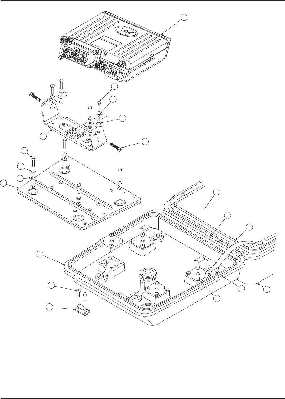
MN003109A01_aa
5-26 Motorcycle Radio Installation Transceiver, Cabling and Multiplexer Installation
Figure 5-20. Installing the Transceiver
11
1
10
15
7
3
6
8
12
13
4
2
9
17
16
14
18
2
6
Draft
D
aft
aft
aft
aft
aft
ft
aft
aft
aft
af
aft
aft
aft
ft
ft
ft
ft
ft
ft
ft
ft
ft
ft
ft
t
f
f
aft
af
aft
aft
Dra
f
ra
ra
af
f
f
f
f
D
Dr
D
D
Dr
ra
r
Dr
Dr
Dr
Dr
Dr
D
D
D
D
D
D
D
D
D
D
D
D
D
D
D
D
D
D
D
D
D
D
D
D
D
D
D
D
D
D
D
D
D
D
D
D
D
D
D
D
D
D
D
D
D
D
D
D
D
D
D
D
D
D
D
D
D
D
D
D
D
D
D
D
D
D
D
D
D
D
D
D
D
D
D
D
D
D
D
D
D
D
D
D
D
D
D
D
D
D
D
D
D
D
D
D
D
D
D
D
D
D
D
D
D
D
D
D
D
D
D
D
D
D
D
D
D
D
D
D
D
D
D
D
D
D
D
D
D
D
D
D
D
D
D
D
D
D
D
D
D
D
D
D
D
D
D
D
D
D
D
D
D
D
D
D
D
D
D
D
D
D
D
D
D
D
D
D
D
D
D
D
D
D
D
D
D
D
D
D
D
D
D
D
D
D
D
D
D
D
D
D
D
D
D
D
D
D
D
D
D
D
D
D
D
D
D
D
D
D
D
D
D
D
D
D
D
D
D
D
D
D
D
D
D
D
D
D
D
D
D
D
D
D
D
D
D
D
D
D
D
D
D
D
D
D
D
D
D
D
D
D
D
D
D
D
D
D
D
D
D
D
D
D
D
D
D
D
D
D
D
D
D
D
D
D
D
D
D
D
D
D
D
D
D
D
D
D
D
D
D
D
D
D
D
D
D
D
D
D
D
D
D
D
D
D
D
D
D
D
D
D
D
D
D
D
D
D
D
D
D
D
D
D
D
D
D
D
D
D
D
D
D
D
D
D
D
D
D
D
D
D
D
D
D
D
D
D
D
D
D
D
D
D
D
D
D
D
D
D
D
D
D
D
D
D
D
D
D
D
D
D
D
D
D
D
D
D
D
D
D
D
D
D

MN003109A01_aa
Motorcycle Radio Installation Installing the Emergency Switch Option 5-27
5.12 Installing the Emergency Switch Option
Use the two-conductor, green/black cable which has as one end terminated with two contacts (part
number 3080221P02) and which is supplied with this W688 Motorcycle Emergency Push Button.
Disconnect the emergency switch shorting plug from the accessory cable. Replace the shorting wire
of the shorting plug with the terminated end of the green/black emergency cable. Reconnect the plug
to the accessory cable.
5.13 Installing the External Alarm Relay Option
The motorcycle radio is offered with only one optional relay connection. If both horn and lights are
required, wire a second relay coil parallel to the first relay. Use the two-conductor green/black cable
which has one end terminated with two contacts (part number 3080221P02) and which is supplied
with this W116 Motorcycle Alarm Relay Option. Insert the contacts into positions 3 and 4 of the
emergency shorting plug of the accessory cable. Refer to Figure 5-26.
5.14 Installing the Headset Accessory
A six-position connector on the accessory cable has been made available for connecting a headset
accessory. Headset manufacturers should be consulted for compatibility with the motorcycle radio
prior to purchase and installation of the headset. To install, disconnect the headset shorting plug.
Remove the headset shorting wire from the headset shorting plug. Terminate the contacts provided
to the applicable wires of the headset cable. Insert the terminated wires into the headset shorting
plug per the contact positions illustrated in the typical headset schematic found in this manual.
Reconnect the terminated headset shorting plug to the accessory cable.
When upgrading from an APX mobile radio, the existing headset cable HLN6890 requires these two
pins to be swapped (see Figure 5-21). The other motorcycle headset cable with this pin change
already performed is called cable 3080010R04.
Table 5-1. Transceiver Installation Parts List
Item No. Description Item No. Description
1Lock washer 10 Ground shield plane
2Flat washer (8 used) 11 Top cover
3Screw 12 Gasket
4Screw 13 Hinge
5Grommet 14 Enclosure mounts
6Screw 15 Transceiver
7Lock catch 16 Screw
8Radio mounting plate 17 Trunnion
9Bottom housing 18 External tooth lock washer (8 used)
Draft
mm
inateinate
xternal Alarm Re
xternal Alarm
offered with only one optiooffered with only on
ay coil parallel to the first ray coil parallel to the
d with two contacts (part nutwo contact
m Relay Option. InseRelay Option. Inse
rt the c
cessory cable. Refer to ry cable. Refe
Fig
essoryessory
ble hable ha
s been made av
s been made
onsulted for comnsulted for com
o install, disstall
shortinhor
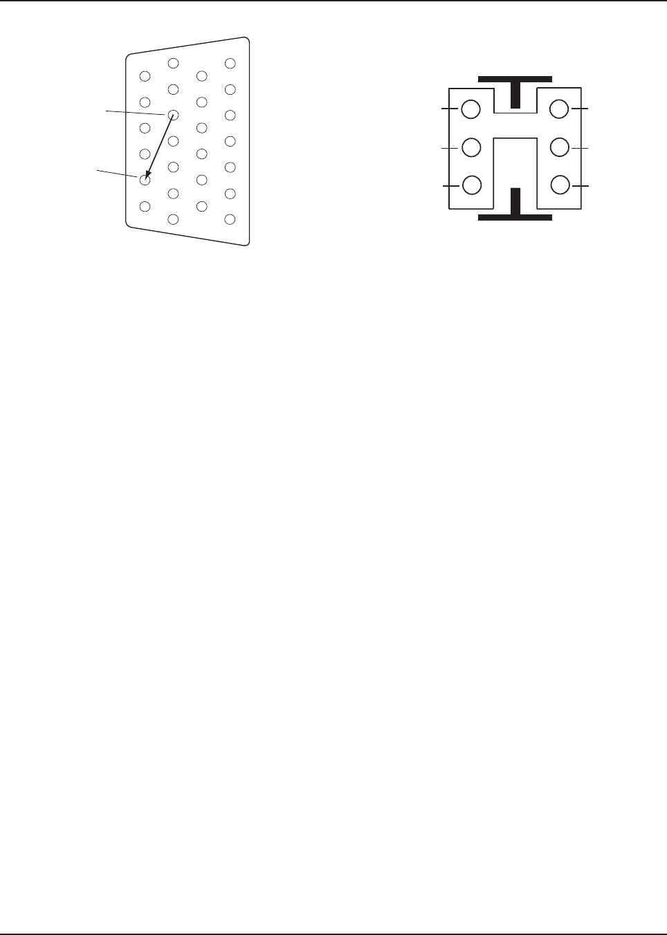
MN003109A01_aa
5-28 Motorcycle Radio Installation
Figure 5-21. Motorcycle Wiring Harness Rework
J2, BACK OF RADIO
Insert into Pin 22
(Monitor)
Remove from Pin 1
(VI P OU T 1 )
1
7
8
14
13
20
21
26
Rework for Handlebar HUB operation when
upgrading existing cable HLN6890.
(Female-Pins)
1
3
5 6
4
2
SPK -
VIP OUT 1
AUX_MIC
SPK +
GND
AUX_PTT
Draft
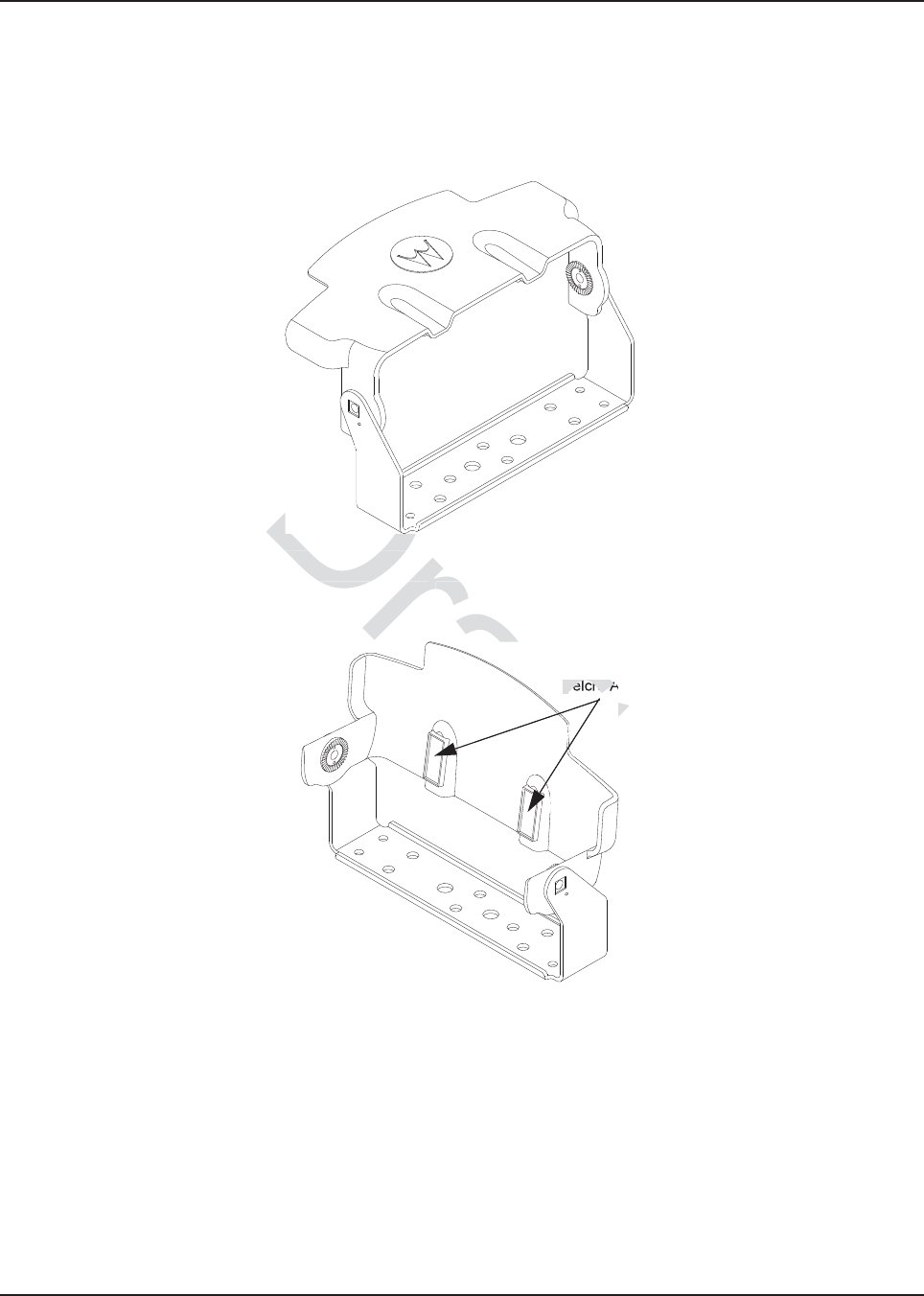
MN003109A01_aa
Motorcycle Radio Installation Installing the O5 Control Head Sunshield 5-29
5.15 Installing the O5 Control Head Sunshield
Install the sunshield (part number NNTN7279_) to the O5 control head as follows.
1. Assemble the sunshield to the remote mount trunnion as shown in Figure 5-22. The same
process can be used for the motorcycle trunnion.
Figure 5-22. Remote Mount Trunnion with Sunshield
2. Position the sunshield as shown in Figure 5-23 and remove the Velcro adhesive backing.
Figure 5-23. Position the Sunshield
Velcro Adhesive Backing
e 5-22. Remote Mount True 5-22. Remote Mo
d as shown in d as shown in
Figure 5-23Figu
D
D
D
D
D
D
D
D
D
D
D
D
D
D
D
D
D
D
D
D
D
D
D
D
D
D
D
D
D
D
D
D
D
D
D
D
D
D
D
D
D
D
D
D
D
D
D
D
raft
ra
ra
ra
ra
ra
ra
t
t
t
t
t
t
t
t
t
t
a
a
ra
ft
ft
ft
t
t
ft
a
ra
a
ft
ft
ft
ra
raft
raft
aft
t
t
t
t
t
ft
t
t
t
t
t
t
t
ft
ft
ft
ft
ft
ft
ft
ft
ft
ra
ra
aft
t
t
t
aft
Ad
Velcro A
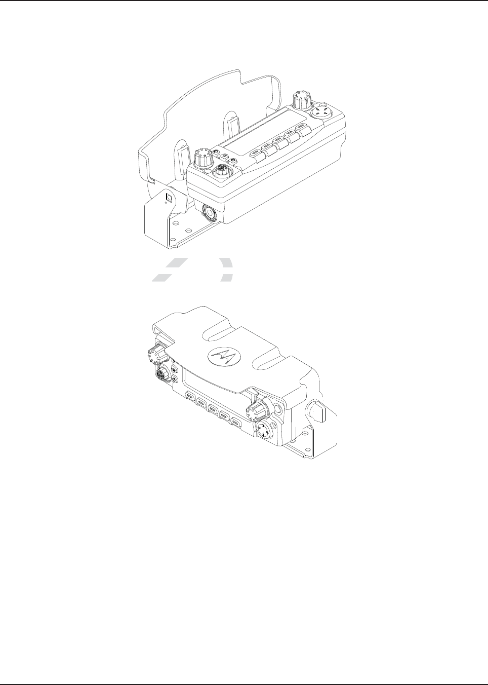
MN003109A01_aa
5-30 Motorcycle Radio Installation
3. Slide the control head onto the trunnion while aligning the edge of the control head with the
edge of the sunshield as shown in Figure 5-24. Make sure the Velcro properly adheres to the
control head.
Figure 5-24. Slide the Control Head onto Trunnion
4. Position control head as desired and install screws as shown in Figure 5-25.
Figure 5-25. Position Control Head as Desired
Draft
5-24. Slide the Co5-24. Slide the C
ead as desired and insta
ead as desired and
D
D
D
Draft
Draft
D
D
D
Dr
r
Dra
Dra
ra
ra
r
ra
ra
ra
ra
ra
ra
a
a
ra
a
a
a
raf
a
af
af
aft
af
af
a
af
af
af
af
af
a
a
ft
f
ft
ft
ft
ft
ft
ft
f
ft
ft
af
f
ft
f
ft
ft
f
f
f
ft
f
t
t
f
Dra
Dra
Dra
a
f
f
ft
ft
ft
f
f
ft
aft
f
f
f
r
ft
ft
f
ft
ft
ft
ft
ft
ft
f
f
f
f
f
ft
f
f
ft
ft
ft
ft
ft
ft
ft
a
a
ft
ft
ft
ft
ft
ft
ft
ft
ft
ft
ft
ft
ft
ft
ra
Dra
ft
ft
ft
ft
ft
ft
t
af
af
ft
ft
ft
ft
ft
ft
ft
ft
ft
ft
ft
ft
ra
Dr
af
Dr
Dr
Dra
ra
af
Dra
raf
af
ft
af
ft
ft
ft
ft
t
t
ft
ft
ft
ft
ft
ft
ft
ft
ft
ft
ft
ft
ra
Dr
Dr
Dr
Dr
f
f
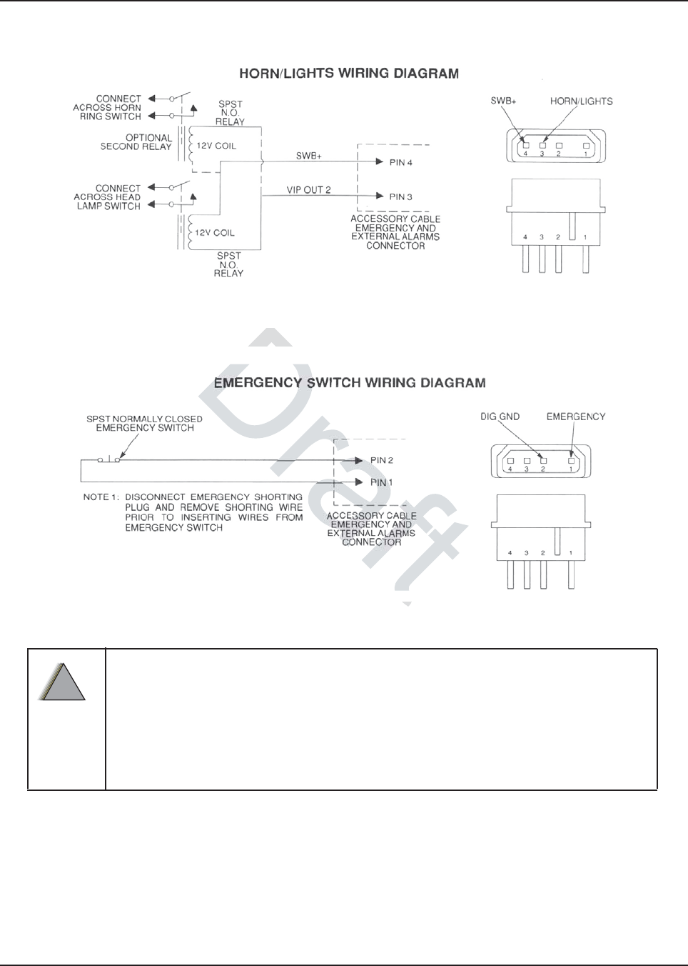
MN003109A01_aa
Motorcycle Radio Installation Horn/Lights Wiring 5-31
5.16 Horn/Lights Wiring
Figure 5-26. Horn/Lights Wiring Diagram
5.17 Emergency Switch Wiring
Figure 5-27. Emergency Switch Wiring Diagram
Motorcycle products must have pins 1 and 2 connected together to allow the
radio to power down. Opening this connection by REMOVING the emergency
shorting plug, or pressing the emergency switch, will turn on the radio. Failure
to maintain a normally-closed path could drain the vehicle battery if left
unchecked.
EMERGENCY-equipped radios are capable of TRANSMITTING without warning.
!
W A R N I N G
!
Draft
WiringWiring
Wi
Wi

MN003109A01_aa
5-32 Motorcycle Radio Installation Emergency Switch Wiring
Draft

Chapter 6 Finishing the Installation
6.1 Cable Connection
6.1.1 O2 Control Head
Perform the following if it has not been previously done:
1. Remove the control head from its mounting trunnion. Plug the radio’s CAN cable into the
proper location on the back of the control head (see Figure 2-21 and Figure 2-23 in
Chapter 2). The connectors “click” when snapped into place. The control head model can
have the microphone plugged into the lower left corner of the control head front panel.
2. Connect the plug from the speaker lead to the mating connector coming out of the power
cable.
3. Plug the VIP connector into the correct location on the back of the control head.
4. Connect the CAN cable to the proper location on the transceiver.
NOTE: Connector-protective covers are provided with the radio. They should be used for added
environmental robustness.
Be sure the control head and microphone PTT switches are OFF. Install the 15-amp fuse in
the radio power cable fuseholder and the 3- or 4-amp fuse(s) in the ignition sense cable
fuseholder(s).
Turn the radio ON at the control head and verify proper operation of all controls and indicators.
Radio operation in some installations require turning on the ignition sense. Perform a
complete operational check of the radio.
Dress the control and power cables out of the way to prevent damage (pull any excess cable
into the trunk area) securing with clamps and tie wraps where necessary.
6.1.2 O3 Control Head
Perform the following if it has not been previously done:
1. Unplug the CAN coiled cable connector on the Transceiver Interface. Plug in the connector
again. A “click” sound should be heard. Ensure location of CAN connector is correct
(i.e. J800L or J800R) on the transceiver interface.
Connect the plug from the speaker lead to the mating connector of J2.
6.1.3 O5 Control Head
Perform the following if it has not been previously done:
1. Remove the control head from its mounting trunnion. Plug the radio's CAN cable into the
proper location on the back of the control head (see Figure 2-21 and Figure 2-23 in
Chapter 2). The connectors “click” when snapped into place. The control head model can
have the microphone plugged into the lower left corner of the control head front panel.
2. Connect the plug from the speaker lead to the mating connector coming out of the power
cable.
Draft
to t
to
e to the pe to the p
tive covers are prtive covers are
robustness.robus
ol head and microphone PTol head and microph
e fuseholder and the 3- or older and t
ol head and verify proper ohead and verify proper o
pp
tions require turning on the
tions require turning on th
adio.dio.
the way to pthe way t
d tie wrtie w

MN003109A01_aa
6-2 Finishing the Installation Cable Connection
3. Plug the VIP connector into the correct location on the back of the control head.
4. Connect the CAN cable to the proper location on the transceiver.
6.1.4 O7 Control Head
Perform the following if it has not been previously done:
1. Remove the control head from its mounting trunnion. Plug the radio's CAN cable into the
proper location on the back of the control head (see Figure 2-21 and Figure 2-23 in
Chapter 2). The connectors “click” when snapped into place. The control head model can
have the microphone plugged into the lower left corner of the control head front panel.
2. Connect the plug from the speaker lead to the mating connector coming out of the power
cable.
3. Plug the VIP connector into the correct location on the back of the control head.
4. Connect the CAN cable to the proper location on the transceiver.
6.1.5 O9 Control Head
Perform the following if it has not been previously done:
1. Remove the control head from its mounting trunnion. Plug the radio's CAN cable into the
proper location on the back of the control head (see Figure 2-22 and Figure 2-23 in
Chapter 2). The connectors “click” when snapped into place. The control head model can
have the microphone plugged into the MMP connection on the control head back panel.
2. Connect the plug from the speaker lead to the mating connector coming out of the power
cable.
3. Plug the VIP connector into the correct location on the back of the control head.
4. Connect the CAN cable to the proper location on the transceiver.
Draft
been been
ad from its moad from its m
e back of the contre back of the co
onnectors “click” when s
onnectors “click” w
one plugged into the MMP ne plugged into t
m the speaker lead to the mthe speaker lead to
the correct lohe correct lo
cation on thecation
roper location on the transer location on the trans
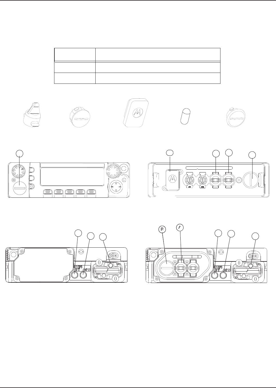
MN003109A01_aa
Finishing the Installation Dust Cover Installation 6-3
6.2 Dust Cover Installation
To help protect and ensure debris does not effect or damage your unused connectors, please use
the provided dust covers. Refer to Figure 6-1 to determine which cover is for which connector.
Figure 6-1. Dust Cover Installation Locations
NOTE: Parts B and E require inserting then turning approximately 1/3 turn using a coin as a tool until
it contacts the stop.
Part C shall be installed onto DB25 accessory cable assembly when the corresponding cable
assembly connection is not in use.
Table 6-1 Dust Cover Kit Number
Kit Number Description
KT000245A01 Dash Mount
KT000246A01 Remote Mount
A: 1515047C01 B: 1515048C01 C: 7575262A01 D:SL000319A01 E: 1515327H02
Control Head
APX 8500 Rear (with no TIB)
BCAE
A
Control Head (Rear)
APX 8500 Rear (with TIB)
BA
DDC
DDC
Draft
Dra
Dra
Dr
Dr
ra
ra
ra
D
D
Dr
Dr
Dr
Dr
Dr
ra
ra
ra
ra
Dr
Dr
Dr
Dr
Dr
D
D
D
Dr
D
D
D
D
D
D
Dr
Dr
Dr
Dr
D
D
Dr
Dr
Dr
Dr
Dr
D
D
D
D
D
D
D
D
Dr
Dr
Dr
Dr
Dr
Dr
Dr
D
Dr
Dr
Dr
D
Dr
Dr
Dr
Dr
Dr
Dr
Dr
Dr
Dr
D
Dra
D
D
D
D
D
Dr
Dr
D
Dr
D
r
Dr
D
ra
Dr
Dr
ra
r
Dr
Dr
Dr
ra
Dra
ra
ra
r
r
r
ra
ra
r
ra
ra
ra
ra
ra
r
r
r
r
r
r
Dr
Dr
Dr
Dr
D
Dr
D
Dr
Dr
Dr
Dr
Dr
Dr
Dr
Dr
Dr
Dr
Dr
D
D
Dr
D
Dr
Dr
D
Dr
Dr
Dr
Dr
Dr
Dr
Dr
Dr
Dr
Dr
Dr
Dr
D
Dr
Dr
Dr
Dr
Dr
Dr
Dra
D
Dr
Dr
Dr
Dr
Dr
Dr
Dr
Dr
D
D
D
D
D
Dr
Dr
Dr
D
D
D
ra
D
Dr
D
D
Dra
Dra
Dr
D
D
D
D
D
D
D
D
D
D
Dr
Dr
Dr
Dr
Dr
Dr
Dr
Dr
r
ra
Dr
Dr
Dr
Dr
Dr
Dr
Dr
Dr
Dr
Dr
Dr
D
Dr
Dr
Dr
Dr
Dr
Dr
Dr
Dr
Dr
D
D
D
D
D
D
D
D
Dr
Dr
Dr
Dr
Dr
Dr
Dr
Dr
Dr
D
D
D
D
D
D
D
D
Dr
D
D
Dr
D
D
D
D
D
D
Dr
D
Dr
D
Dr
Dr
D
Dr
Dr
Dr
Dr
Dr
Dr
Dr
Dr
Dr
Dr
Dr
Dr
Dr
Dr
Dr
Dr
Dr
Dr
Dr
ra
r
ra
Dra
D
D
Dr
Dr
Dr
Dr
D
ra
D
Dr
D
Dr
D
D
Dr
Dr
Dr
Dr
ra
Dr
Dr
ra
Dr
Dra
Dra
Dra
Dra
Dra
Dra
Dra
Dra
Dra
Dra
Dra
Dra
Dra
Dra
Dra
Dra
Dra
Dra
Dra
Dra
Dra
Dra
Dra
Dra
Dra
Dra
Dra
Dra
Dra
Dra
Dra
Dra
Dra
Dra
r
r
r
r
r
r
r
r
r
r
r
r
r
r
r
r
r
r
r
r
r
r
r
r
r
r
r
r
r
r
r
Dr
r
af
af
af
af
a
a
a
a
af
a
a
a
a
a
a
a
af
af
a
a
a
a
a
a
a
a
a
a
a
a
a
a
a
a
a
a
a
a
a
a
a
a
a
a
a
a
a
a
a
a
a
a
a
a
a
a
a
a
a
a
a
a
a
a
a
a
a
a
a
a
a
a
a
a
a
a
a
a
a
a
a
a
a
a
a
a
a
a
a
a
a
a
a
a
a
a
a
a
a
a
a
a
a
a
a
af
a
a
af
af
af
a
a
af
af
a
a
a
a
a
a
ft
ft
ft
ft
B
ft
ft
ft

MN003109A01_aa
6-4 Finishing the Installation Dust Cover Installation
Draft

Chapter 7 Best Practices: Installation & Troubleshooting
In this section are Motorola recommended vehicle installation practices that can address or prevent
many issues, including:
• Radio circuit damage due to over voltage condition
• Radio/Accessories "lock up"
• Radio/Accessories change state/lock-up when radio PTT is depressed
• Radio powers up in the FL 01/90 state (general communication error code)
• Radio intermittently resets
• Radio loses secure key
• Transmit audio distortion on motorcycle radio when engine is running
• Keypad buttons become inoperative for motorcycle radios when engine is running
• Alternator whine present when transmitting with engine running
• Radio/Accessories turn themselves on/off
7.1 Check Wiring of Ignition and Radio Ignition Sensing
• If it is required to turn the radio on and off via the ignition sense switch, in addition to the control
head’s on/off switch, connect the ignition sense lead to the accessory terminal from the ignition
switch (usually in the vehicle’s fuse panel under accessory or radio).
NOTE: Motorola Solutions recommends protecting or isolating the radio’s ignition sense input from
voltage spikes in excess of +/- 40VDC. Such spikes can be hundreds of volts in amplitude and
are common in larger vehicles (utility trucks, buses and etc.), especially when the source is
common to a solenoid coil. A triggerable oscilloscope is required to determine the existence of
such spikes as most voltmeters cannot measure in short duration (< 1 msec). If the condition of
the intended ignition sense source is unknown, Motorola Solutions recommends isolating the
source from the radio with a relay or the use of a suppression diode wired between the source
and ground. Any high current suppression diode (i.e. MR2535) with a breakdown voltage of
between 18 and 40 volts will suffice. A suitable diode kit is available from Motorola Solutions
parts, kit number HLN6325_.
• If it is required to have the radio power up only via the control head’s on/off switch, then connect
the ignition sense lead directly to the positive terminal of the battery. This will mean the ignition
sense will always be ignored and a re-wiring will be necessary in the future if the operator
chooses any ignition sense CPS setting.
Draft
no
no
ent when ent when
turn themselves turn themselv
of Ignition
of Ignition
and Rad an
urn the radio on and off viarn the radio on and
connect the ignition sense t the ignitio
hicle’s fuse panel under accle’s fuse panel un
ends protecting or isols protecting or
atingating
40VDC. Such spikes can b0VDC. Such spikes can
lity trucks, buses and etc.)
lity trucks, buses and et
ble oscilloscope isble oscilloscope is
req
r
measure measure
in shorin shor
ow
n, Moton, M
of a s
f a

MN003109A01_aa
7-2 Best Practices: Installation & Troubleshooting
Check Physical Installation of Radio Ground and Radio Accessory Wiring
7.2 Check Physical Installation of Radio Ground and Radio Accessory
Wiring
• Take care to scrape away paint on the chassis at the place where the ground connection is to
be made, and try to keep the ground lead as short as possible.
NOTE: Some vehicles have dedicated ground points. If available, use the ground points for the radio
ground connection.
• Verify that the A+ lead (red) is connected directly to the positive terminal of the battery and
the ground lead (black) is connected to the vehicle’s chassis using as short of a length of
wire as is practical.
• For vehicles that have other types of electronic equipment installed (lights, flashers,
computers siren/PA and etc.), use a separate ground for the mobile radio equipment.
• Make sure that the mobile radio antenna is the minimum required distance (three feet) from
the mobile radio equipment to prevent radio frequency interference (RFI) from interfering
with the radio and/or accessories.
NOTE: If multiple radios/antennas are installed, ensure that the minimum antenna separation
requirements are met.
• Do not coil up any excess length of the A+ (red) lead. Doing this may cause a large transient
voltage to be produced when there is a high current drain (e.g. during transmit). This could
cause the radio to reset when the push-to-talk (PTT) is depressed.
• For motorcycle mounted radios, make sure that the antenna ground connection is solid. An
intermittent ground connection can cause the transmission to be distorted when the
motorcycle’s engine is running.
• Do not coil up any excessive length of antenna cable, if possible. It may affect the radio’s
receive performance.
• If an extra length of cable is used to extend the microphone, make sure the added
capacitance does not interfere with the operation of the radio.
7.3 Improve the Electrical Quality of the Power and Ignition Lines
• Use a relay to isolate the vehicle’s ignition switch point (ACC) from the radio’s ignition sense
point. Control this relay from the vehicle’s ignition switch point (ACC). Supply a cleaner
voltage from the positive terminal of the battery into the relay, which will now be attached to
the radio’s ignition sense point. Now the ACC line toggles the relay, instead of directly
toggling the radios ignition sense line.
• Install a Power Line Filter between the A+ lead and the positive terminal of the battery. This is
intended to filter the battery power applied to the transmitter power amplifiers. Pay extra
caution to this because the series filter will introduce a negative spike when the radio
transmits that may cause problems with radio operation.
• For vehicles that use electromechanical relays to control external devices (lights, motors,
switch boxes and etc.), these relay circuits should be isolated as best as possible from the
mobile radio equipment. Also, diode suppression should be used across the relay contacts to
minimize the noise produced by the collapsing magnetic field.
• If the ignition sense switch is to be used, make sure that there is not a large voltage drop
between the A+ point (usually the positive terminal of the battery) and the ignition sense
point. In general, the voltage difference between these two points, should not be greater than
1.5 volts when all accessories/air-conditioner, etc. are turned on. Refer to the Basic Service
Manual for specifications for minimum and maximum voltage levels. Typical battery voltage
levels are 13.6V +/- 20%.
Draft
ar
cess length of thcess length of
uced when there is a uced when there i
o reset when the push-to-
o reset when the p
nted radios, make sure thanted radios, make
nection can cause the nection can cause
tra
nning.g.
length of antenna length of antenna
cable, ifc
o extend the microphone, m
extend the microphone,
e operation of the radio.
operation of the radio
he Power he Powe
h poinpo

MN003109A01_aa
Best Practices: Installation & Troubleshooting Minimize the Effect of Poorly Grounded Antennas 7-3
7.4 Minimize the Effect of Poorly Grounded Antennas
• For vehicles with high power radios that use glass mount antennas, care must be taken to
keep the radio and antenna cable as far as possible from the radiating element of the
antenna. If a sufficient distance is not maintained, the glass mount antenna’s lack of a proper
ground plane may cause the radio’s transmit signal to interfere with itself and cause a reset.
To minimize this effect, it may be necessary to install ferrite beads on the antenna cable to
protect the radio from this interference.
7.5 Jump-Start the Vehicle
Jump-starting a motorcycle can crank 300+ volts through the vehicle’s charging system and these
transients can damage electrical equipment.
The state of your radio prior to needing a jump-start may be unknown, and the radio may attempt to
return to its last state (radio ON), when doing a jump-start. Therefore, Motorola recommends the
following steps be taken before jump-starting any vehicle containing a radio.
1. Locate the ignition sense line (thin yellow wire or thin red wire, depending on dash mount or
remote mount installation) and the main power leads (thick red wire) near the battery positive
terminal.
NOTE: These lines are fused. In the event these lines are not fused (add the appropriate fuse in line)
use whatever tools necessary to physically disconnect the ignition sense and power lines
from the battery terminal.
Make sure that the disconnected lines are not in the way of moving motorcycle parts or
interfering with the motorcycle operation in any way.
2. Open up the fuse holders and remove the fuses out of the kits.
3. Re-tighten the fuse holders but without the fuses to insure that ignition sense and power lines
do not interfere with moving motorcycle parts.
4. Proceed with the jump-start routine as described by your vehicle owner’s manual.
5. Once the jump-start process is complete, re-install the fuses into their holders.
7.6 Eliminate Noise/Howling from PA Speaker
1. Refer to Section 2.1.1 for recommended methods of installation available for the mobile
two-way radio, with accessories placed on or inside the vehicle.
2. Refer to Section 2.1.2 for the wiring diagrams for the recommended configurations.
3. Refer to the Siren/PA User Manual for further details on lowering the wattage.
Do not jump-start vehicle with radio power or ignition sense cables connected.
Damage to the radio and/or accessories may result.
!
C a u t i o n
Draft
al equial equ
r to needing a r to needing a
dio ON), when doindio ON), when d
g
en before jump-starting a
en before jump-star
n sense line (thin yellow wn sense line (thin ye
ation) and the main poweration) and the main
he event these lines are noe event these lines
y to physically o physically
disconnect tdisconnect t
are not in the way ore not in the way
n any way.n any way
es ou
s o

MN003109A01_aa
Notes
7-4 Best Practices: Installation & Troubleshooting
Draft

Appendix A Replacement Parts Ordering
A.1 Basic Ordering Information
When ordering replacement parts or equipment information, the complete identification number
should be included. This applies to all components, kits, and chassis. If the component part number
is not known, the order should include the number of the chassis or kit of which it is a part, and
sufficient description of the desired component to identify it.
The ASTRO APX Mobile Radio Basic Service Manual includes complete parts lists and part
numbers.
Refer to Table of Content for applicable manual numbers.
A.2 Motorola Online Service and Support
For general support, users can access
• http://www.motorolasolutions.com/en_us/support.html
• http://www.motorolasolutions.com/en_us/contact-us.html
• http://www.motorolasolutions.com/en_us/products/two-way-radios/project-25-radios/mobile-
radios/apx8500.html
• Motorola Online Website: https://businessonline.motorolasolutions.com/
To register for online access:
• Domestic customers: please call 800-814-0601 (U.S. and Canada).
• International customers: please go to https://businessonline.motorolasolutions.com/ and click
on “Sign Up Now.”
Dr
s.c
s.c
tionstions
.com/.com/
solutions.com/en_solutions.com/e
tmltml
Website: https://busWebsite: https://bu
inesson
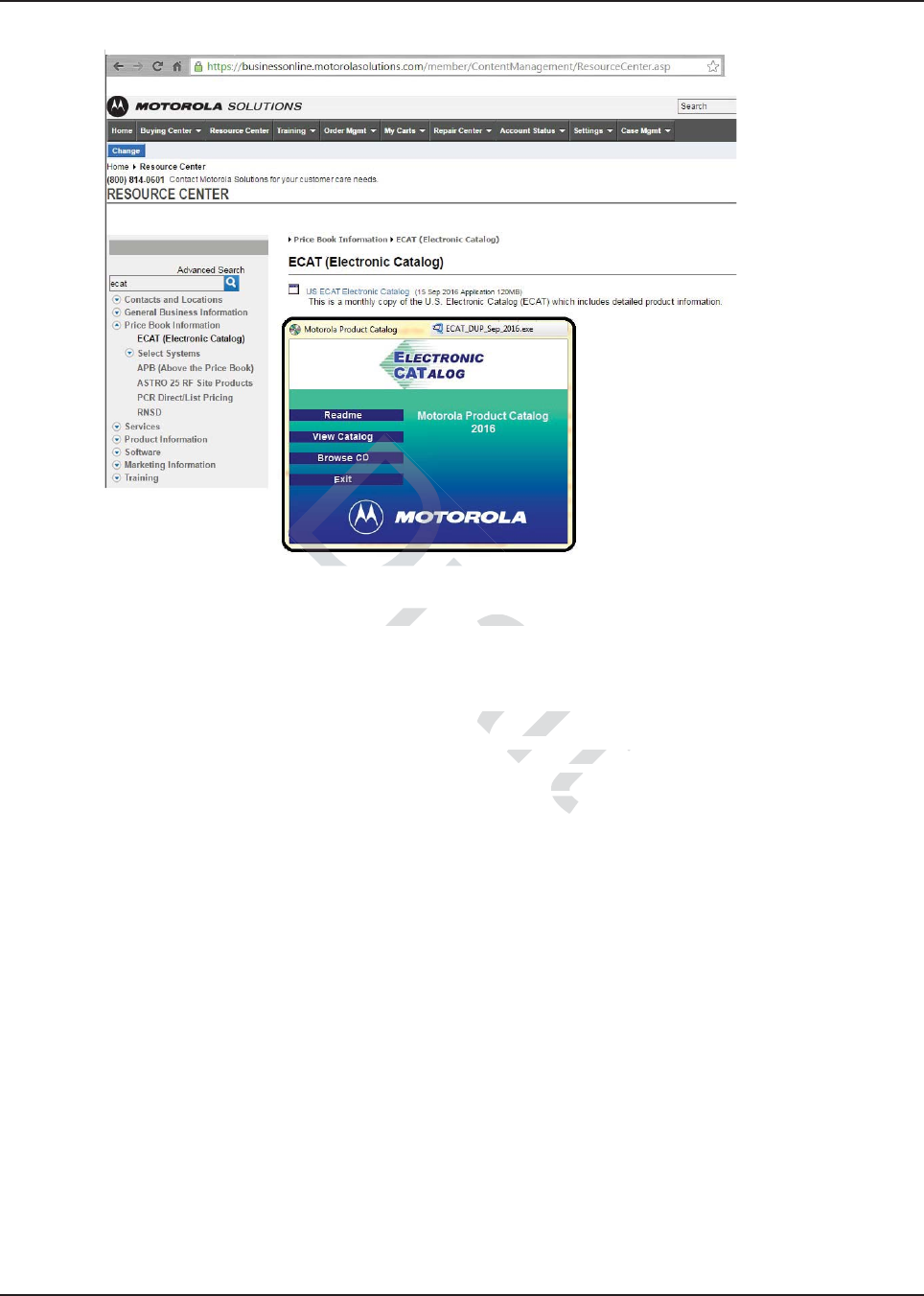
MN003109A01_aa
A-2 Replacement Parts Ordering Accessories Aftermarket Division (AAD)
•ECAT
As a registered user, you have access to the electronic catalogue for purchasing accessories and
radios.
A.3 Accessories Aftermarket Division (AAD)
The Accessories Aftermarket Division is able to provide Motorola Solutions Branded accessories for
all your radio needs. Contact Motorola Solutions after you have a KIT number, identified from the
Motorola Online website and/or the ECAT catalog. You can contact them at: 800-422-4210.
Draft
cess to the elss to t
ectronic cataectron
ion (AAD)on (AAD
ovide Motorola Svide Motorola S
ryou have u ha
can coan c

Index Index
A
accessories
connector assembly .......................................4-1, 4-9
assembly ......................................................... 4-10
disassembly ....................................................... 4-9
exploded view .................................................. 4-10
connector pins ....................................................... 4-8
headset ........................................................5-2, 5-27
installing
dash mount ........................................................ 4-1
horn relay ........................................................... 4-3
light relay ........................................................... 4-3
remote mount .................................................... 4-9
antenna ..................................................................... 5-5
cable, see Cables, antenna
installing ..................................................... 2-32, 5-21
motorcycle ............................................................. 5-2
mounting ............................................................. 2-32
site ....................................................................... 2-32
B
base stations ........................................................... 1-11
black lead ..............................................2-30, 5-22, 5-27
C
cables ................................................5-3, 5-4, 5-5, 5-24
accessory .....................................4-1, 4-2, 5-22, 5-27
antenna ............................................................... 2-18
battery ................................................................... 4-9
connection ......................................................6-1, 7-1
diagrams ...........................................2-22, 5-21, 5-25
emergency .......................................................... 5-27
excess ................................................................. 5-24
ignition ................................................................... 4-9
microphone ..................................................5-2, 5-12
motorcycle control head ...............5-1, 5-9, 5-11, 5-22
motorcycle control head, installing ...................... 5-21
motorcycle transceiver ........................................ 5-24
power .........................................................2-30, 5-22
remote mount ...................................................... 2-21
routing ................................................................. 5-22
speaker ...............................................5-2, 5-14, 5-21
configurations
dash mount ........................................................... 1-6
motorcycle ........................................................... 1-11
multi control ......................................................... 1-11
remote mount ........................................................ 1-8
control head ..............................................2-26, 4-6, 4-8
cabling ................................................................. 2-21
diagrams ....................................................2-22, 2-23
multi ..................................................................... 1-11
remote mount ........................................................ 1-8
control stations ........................................................ 1-11
D
dash mount
accessories installations ....................................... 4-1
configuration ......................................................... 1-6
installation examples ............................................. 2-2
radio dimensions ..............................1-1, 1-2, 1-3, 1-4
trunnion ............................................................... 2-19
E
emergency footswitch ............................................... 4-1
emergency pushbutton ............................................. 4-1
emergency switch
installing .............................................................. 5-27
wiring ................................................................... 5-31
external alarm
installing .............................................................. 5-27
see also Horn relay or Light relay
F
footswitch, emergency .............................................. 4-1
H
horn relay .........................................4-2, 4-3, 5-27, 5-31
I
ignition
cable ..................................................................... 4-9
wire ..................................................................... 5-22
wire, for motorcycle ............................................... 5-2
installation
examples ............................................................... 2-2
important hints ...................................................... 5-4
order of .................................................................. 5-5
J
J2 ....................................................................... 4-7, 4-8
L
leads
black .................................................. 2-30, 5-22, 5-27
light relay .........................................4-2, 4-3, 5-27, 5-31
locking kit, installing ................................................ 2-29
M
microphone ........................................................ 5-2, 5-4
hang-up clip, installing ........................................ 5-14
hang-up clip, standard ................. 2-38, 5-5, 5-9, 5-11
mounting ............................................................... 5-4
motorcycle
antenna ................................................................. 5-2
configuration ........................................................1-11
control head cable ................................................. 5-1
Draft
........
.......
.............
............
................. 2-3................. 2-
..................... 1-11..................... 1-11
2-30, 5-22, 5-27-30, 5-22, 5-27
5-2424
77
H
horn re
II
ignitionignition
cable .................cable ................
wire .......................
wire .....................
wire, for motorcycle
e, for motorcycl
installationinstallati
examples .........examples ....
portant hintstant h
r of ....of .

Index-2
MN003109A01
display unit ............................................................ 5-1
external speaker .................................................... 5-2
headset ................................................................. 5-2
ignition wire ........................................................... 5-2
installation ............................................................. 5-3
antenna ............................................................ 5-21
cables .............................................................. 5-21
cabling ............................................................. 5-24
control head ....................................................... 5-7
emergency switch ...................................5-27, 5-31
external alarm .................................................. 5-27
fuel tank console ..............................5-9, 5-10, 5-12
handlebar .................................................. 5-8, 5-11
headset ............................................................ 5-27
horn/lights wiring .............................................. 5-31
microphone hang-up clip ................................. 5-14
speaker ..................................................... 5-7, 5-14
transceiver .............................................. 5-24, 5-26
universal mounting plate .................................... 5-6
weather-resistant enclosure ............................. 5-23
microphone ........................................................... 5-2
transceiver ............................................................. 5-1
mounting configurations .......................................... 2-18
dash ............................................................. 1-6, 2-19
motorcycle ........................................................... 1-11
multi control ......................................................... 1-11
remote ..........................................................1-8, 2-21
mounting plate, universal ............................5-1, 5-3, 5-5
installing ................................................................ 5-6
mounting, antenna
restrictions ........................................................... 2-32
roof top ................................................................ 2-32
trunk lid ................................................................ 2-32
multi control
configuration ........................................................ 1-11
O
ordering replacement parts .......................................A-1
P
parts, ordering replacement ......................................A-1
pin
SW B+ .....................................................4-3, 4-7, 4-8
VIP in ..................................................................... 4-8
VIP out ............................................................ 4-3, 4-7
pushbutton, emergency ............................................ 4-1
R
relays
horn ..............................................4-2, 4-3, 5-27, 5-31
light ...............................................4-2, 4-3, 5-27, 5-31
remote mount
accessory installations .......................................... 4-9
cabling ................................................................. 2-21
configuration .......................................................... 1-8
control cable installation ...................................... 2-26
installation examples ............................................. 2-2
trunnion ............................................................... 2-21
replacement parts, ordering ......................................A-1
S
speaker ..................................................................... 5-5
cable, see Cables, speaker
external ................................................................. 5-2
fuel tank console installation ............... 5-9, 5-10, 5-12
handlebar installation .......................... 5-8, 5-11, 5-12
installing ................................................ 5-7, 5-9, 5-14
mounting ............................................................. 2-35
T
trunnion ................................................................... 2-22
bracket for speaker ............................................. 2-35
dash mount ......................................................... 2-19
diagrams ............................................................. 2-22
locking kit ............................................................ 2-29
motorcycle installation ......................................... 5-25
mounting bracket ................................................ 2-19
remote mount ............................................... 1-8, 2-21
transmission hump mounting .............................. 2-20
U
universal mounting plate ............................. 5-1, 5-3, 5-5
installing ................................................................ 5-6
V
VIP
connector ....................................................... 4-2, 6-2
input connections .................................................. 4-8
output connections ................................................ 4-7
W
wiring diagrams ........................................................ 2-3
Draft
....
...
............
...........
.........1-6, 2-.........1-6, 2-
..................... 1-11..................... 1-1
........................ 1-11........................ 1-1
.................... 1-8, 2-21
.................... 1-8, 2-2
...........
.....5-1, 5-3, 5-5.....5-1, 5-3, 5
....................... 5-6....................... 5-6
............. 2-32.... 2-3
......... 2-32.......
..... 2-32..... 2-32
-1111
VV
VIPVIP
connector ....onne
input connectionsinput connection
output connections output connection
WW
g diagrams agra

Glossary Glossary
This glossary contains an alphabetical listing of terms and their definitions that are applicable to the
ASTRO radio.
Term Definition
band Frequencies allowed for a specific purpose.
CPS See Customer Programming Software.
Customer
Programming
Software
Software with a graphical user interface containing the feature set of an
ASTRO radio.
default A pre-defined set of parameters.
D.E.K Direct Entry Keyboard.
digital Refers to data that is stored or transmitted as a sequence of discrete
symbols from a finite set; most commonly this means binary data
represented using electronic or electromagnetic signals.
FCC Federal Communications Commission.
firmware Code executed by an embedded processor such as the Host or DSP in
a subscriber radio. This type of code is typically resident in non-volatile
memory and as such is more difficult to change than code executed
from RAM.
frequency Number of times a complete electromagnetic-wave cycle occurs in a
fixed unit of time (usually one second).
GLONASS GLObalnaya NAvigatsionnaya Sputnikovaya Sistema: The Russian
Global Navigation satellite system, consisting of at least 24 operational
satellites which fly in medium Earth orbit at an altitude of approximately
19,130 km. Each satellite circles the Earth slightly faster than twice a
day. GLONASS provides Time and Location to anywhere on Earth,
where there is an unobstructed line of sight to four or more GPS
satellites. A GLONASS receiver triangulates its position using these
satellites.
GNSS Global Navigation Satellite System: Standard generic term for satellite
navigation systems that provide geo-spatial positioning with global
coverage. This term includes GPS, GLONASS, Galileo, Beidou and
other regional systems. GNSS is a term used worldwide The advantage
to having access to multiple satellites is accuracy, redundancy and
availability at all times.
Draft
ned setned se
ct Entry Keyboardct Entry Keyboa
efers to data that is stor
efers to data that
bols from a finite set; mobols from a finite s
ented using electronic ented using electr
or
mmunications Commissmmunications Co
by an embedded procesan embedded proces
. This type of code This type of code
is typ
s ty
is more difficult to cha
is more difficult to ch
e electromectr
seco
eco

MN003109A01_aa
Glossary-2
GPS Global Positioning System: U.S.A.’s Satellite based radio navigation
system developed by the U.S. Department of Defense and operated by
the U.S. Air Force, which consists of at least 24 operational satellites
which fly in medium Earth orbit at an altitude of approximately 20,180
km. Each satellite circles the Earth twice a day. GPS provides Time and
Location to anywhere on Earth, where there is an unobstructed line of
sight to four or more GPS satellites. A GPS receiver triangulates its
position using these satellites.
kHz See kilohertz.
kilohertz One thousand cycles per second. Used especially as a radio-frequency
unit.
MCU See microcontroller unit.
MHz See Megahertz.
Megahertz One million cycles per second. Used especially as a radio-frequency
unit.
microcontroller unit Also written as μC. A microprocessor that contains RAM and ROM
components, as well as communications and programming components
and peripherals.
PA Power amplifier.
paging One-way communication that alerts the receiver to retrieve a message.
PTT See Push-to-Talk.
Publication Manual
Revision
A publication that provides supplemental information for its parent
publication before it is revised and reissued.
Push-to-Talk The switch or button that causes the radio to transmit when pressed.
When the PTT switch or button is released, the unit returns to standby
or receive operation.
radio frequency The portion of the electromagnetic spectrum between audio sound and
infrared light (approximately 10 kHz to 10 GHz).
receiver Electronic device that amplifies RF signals. A receiver separates the
audio signal from the RF carrier, amplifies it, and converts it back to the
original sound waves.
registers Short-term data-storage circuits within the microcontroller unit or
programmable logic IC.
RESET Reset line: an input to the microcontroller that restarts execution.
RF See radio frequency.
RX Receive.
Term Definition
Draft
ertz.ertz.
lion cycles per slion cycles pe
written as μC. A microproritten as μC. A mic
nts, as well as communints, as well as com
rals.
ation that alerts the rece
ation that alerts the rec
pplementalemen
nd reisd re

MN003109A01_aa
Glossary-3
signal An electrically transmitted electromagnetic wave.
software Computer programs, procedures, rules, documentation, and data
pertaining to the operation of a system.
time-out timer A timer that limits the length of a transmission.
TOT See time-out timer.
transceiver Transmitter-receiver. A device that both transmits and receives analog
or digital signals. Also abbreviated as XCVR.
transmitter Electronic equipment that generates and amplifies an RF carrier signal,
modulates the signal, and then radiates it into space.
Triangulation A method of determining the relative positions of points in space by
measuring the distances, and sometimes angles, between those points
and other reference points whose positions are known. Triangulation
involves the use of trigonometry. It is commonly used in the navigation
of vehicles, aircraft and boats, and is the method used in the Global
Positioning System, in which the reference points are satellites.
TX Transmit.
UHF Ultra-High Frequency.
Universal Serial Bus An external bus standard that supports data transfer rates of 12 Mbps.
USB See Universal Serial Bus.
VHF Very-High Frequency.
Waypoint Geographic Coordinates of a specific location. It can also be an
Intermediate point on a route or line of travel.
Wi-Fi Wireless Data Transmission protocol 802.11.
XCVR See transceiver.
Term Definition
Draft
the
the
r referenr referen
es the use of tes the use of
ehicles, aircraft andehicles, aircraft
ositioning System, in wh
ositioning System
mit.mit.
Frequency.eque
s standard that supporandard that suppor
ts
ial Bus.al Bus.
a specific lpecif
or liner lin

MN003109A01_aa
Glossary-4
Draft
Draft

Motorola Solutions, Inc.
1303 East Algonquin Road
Schaumburg, Illinois 60196 U.S.A.
MOTOROLA, MOTO, MOTOROLA SOLUTIONS and
the Stylized M logo are trademarks or registered trademarks
of Motorola Trademark Holdings, LLC and are used under license.
All other trademarks are the property of their respective owners.
© 2016 Motorola Solutions, Inc. All rights reserved.
Oct 2016
*MN003109A01*
MN003109A01_AA