Moxa WAPN008 Industrial 802.11n Access Point User Manual AWK 1131A UM 1e 2 0923
Moxa Inc. Industrial 802.11n Access Point AWK 1131A UM 1e 2 0923
Moxa >
Contents
- 1. Users Manual
- 2. (AWK-4131A-XXXXX) UserMan
- 3. (AWK-11xyz-p-t) UserMan
- 4. (AWK-3131A) UserMan
- 5. (TAP-213-XX-CT-T) UserMan 12-29
- 6. TAP-213_UM_e1
- 7. WAPN008- UserMan_0816
- 8. WAPN008- UserMan_AWK-3131A-M12-RCC_20180820
- 9. WAPN008- UserMan_AWK-3131A-M12-RTG_20180820
- 10. WAPN008- UserMan_AWK-3131A-SSC-RTG_20180820
- 11. WAPN008- UserMan_20180911
(AWK-11xyz-p-t) UserMan

AirWorks AWK-1131A User’s Manual
First Edition, July 2014
www.moxa.com/product
© 2014 Moxa Inc. All rights reserved.

AirWorks AWK-1131A User’s Manual
The software described in this manual is furnished under a license agreement and may be used only in accordance
with the terms of that agreement.
Copyright Notice
Copyright © 2014 Moxa Inc.
Reproduction without permission is prohibited.
Trademarks
The MOXA logo is a registered trademark of Moxa Inc.
All other trademarks or registered marks in this manual belong to their respective manufacturers.
Disclaimer
Information in this document is subject to change without notice and does not represent a commitment on the part
of Moxa.
Moxa provides this document as is, without warranty of any kind, either expressed or implied, including, but not
limited to, its particular purpose. Moxa reserves the right to make improvements and/or changes to this manual, or to
the products and/or the programs described in this manual, at any time.
Information provided in this manual is intended to be accurate and reliable. However, Moxa assumes no responsibility
for its use, or for any infringements on the rights of third parties that may result from its use.
This product might include unintentional technical or typographical errors. Changes are periodically made to the
information herein to correct such errors, and these changes are incorporated into new editions of the publication.
Technical Support Contact Information
www.moxa.com/support
Moxa Americas
Moxa China (Shanghai office)
Toll-free: 1-888-669-2872 Toll-free: 800-820-5036
Tel: +1-714-528-6777 Tel: +86-21-5258-9955
Fax: +1-714-528-6778 Fax: +86-21-5258-5505
Moxa Europe Moxa Asia-Pacific
Tel: +49-89-3 70 03 99-0 Tel: +886-2-8919-1230
Fax: +49-89-3 70 03 99-99 Fax: +886-2-8919-1231
Table of Contents
1.
Introduction ......................................................................................................................................
1-1
Overview .......................................................................................................................................... 1-2
Package Checklist .............................................................................................................................. 1-2
Product Features ................................................................................................................................ 1-2
Product Specifications ......................................................................................................................... 1-3
Functional Design .............................................................................................................................. 1-6
LAN Port .................................................................................................................................... 1-6
LED Indicators ........................................................................................................................... 1-6
Beeper ...................................................................................................................................... 1-7
Reset Button .............................................................................................................................. 1-8
2.
Getting Started ..................................................................................................................................
2-1
First-time Installation and Configuration ............................................................................................... 2-2
Communication Testing ...................................................................................................................... 2-3
Function Map ..................................................................................................................................... 2-5
3.
Web Console Configuration ...............................................................................................................
3-1
Web Browser Configuration ................................................................................................................. 3-2
Overview .......................................................................................................................................... 3-3
Basic Settings .................................................................................................................................... 3-4
System Info Settings .................................................................................................................. 3-4
Network Settings ........................................................................................................................ 3-5
Time Settings ............................................................................................................................. 3-6
Wireless Settings ............................................................................................................................... 3-7
Operation Mode ................................................................................................................................. 3-7
Basic Wireless Settings ....................................................................................................................... 3-8
WLAN Security Settings .............................................................................................................
3-10
Advanced Wireless Settings .......................................................................................................
3-17
WLAN Certification Settings (for EAP-TLS in Client mode only) ........................................................
3-19
Advanced Settings ...........................................................................................................................
3-20
DHCP Server (for AP mode only) .................................................................................................
3-20
Packet Filters ...........................................................................................................................
3-21
SNMP Agent .............................................................................................................................
3-24
Link Fault Pass-Through (for Client mode only) .............................................................................
3-26
Auto Warning Settings ......................................................................................................................
3-26
System Log .............................................................................................................................
3-26
Syslog .....................................................................................................................................
3-27
E-mail .....................................................................................................................................
3-28
Trap .......................................................................................................................................
3-30
Status ............................................................................................................................................
3-31
Wireless Status ........................................................................................................................
3-31
Associated Client List (for AP mode only) .....................................................................................
3-31
DHCP Client List (for AP mode only) ............................................................................................
3-32
System Log .............................................................................................................................
3-32
Power Status ...........................................................................................................................
3-33
Maintenance ....................................................................................................................................
3-33
Console Settings ......................................................................................................................
3-33
Ping ........................................................................................................................................
3-33
Firmware Upgrade ....................................................................................................................
3-34
Config Import Export ................................................................................................................
3-35
Load Factory Default .................................................................................................................
3-36
Password .................................................................................................................................
3-36
Misc. Settings ..........................................................................................................................
3-36
Save Configuration ...........................................................................................................................
3-37
Restart ...........................................................................................................................................
3-37
Logout ............................................................................................................................................
3-38
4. Software Installation and Configuration ............................................................................................
4-1
Overview .......................................................................................................................................... 4-2
AWK Search Utility ............................................................................................................................. 4-2
Installing AWK Search Utility ........................................................................................................ 4-2
Configuring AWK Search Utility ..................................................................................................... 4-4
5.
Other Console Considerations ............................................................................................................
5-1
RS-232 Console Configuration (115200, None, 8, 1, VT100) .................................................................... 5-2
Configuration by Telnet and SSH Consoles ............................................................................................ 5-3
Configuration by Web Browser with HTTPS/SSL ...................................................................................... 5-4
Disabling Telnet and Browser Access .................................................................................................... 5-5
A.
References ........................................................................................................................................
A-1
Beacon ..............................................................................................................................................
A-2
DTIM.................................................................................................................................................
A-2
Fragment...........................................................................................................................................
A-2
RTS Threshold ....................................................................................................................................
A-2
B. Supporting Information ....................................................................................................................
B-1
Firmware Recovery .............................................................................................................................
B-2
DoC (Declaration of Conformity) ...........................................................................................................
B-3
Federal Communication Commission Interference Statement ............................................................
B-3
R&TTE Compliance Statement .......................................................................................................
B-3
Professional installation instruction………………………………………………………………………………………………………………B-4

1
1. Introduction
The AWK-1131A industrial a/b/g/n high speed wireless Access Point products are ideal wireless solutions
for hard-to-wire applications that use mobile equipment connected over a TCP/IP network. The AWK-
1131A is rated to operate at temperatures ranging from 0 to 60°C for standard models and -40 to 75°C
for wide temperature models, and is rugged enough for any harsh industrial environment.
The following topics are covered in this chapter:
Overview
Package Checklist
Product Features
Product Specifications
Functional Design
LAN Port
LED Indicators
Beeper
Reset Button

AirWorks AWK-1131A Introduction
Overview
The AWK-1131A industrial wireless AP/client meets the growing need for faster data transmission speeds by
supporting IEEE 802.11n technology with a net data rate of up to 300 Mbps. The AWK-1131A is compliant
with the industrial standards and approvals, covering operating temperature, power input voltage, surge,
ESD and vibration. The two redundant DC power inputs increase the reliability of the power supply. The
AWK-1131A can operate on either the 2.4 or 5 GHz bands and is backwards-compatible with existing
802.11a/b/g deployments to future-proof your wireless investments.
Package Checklist
Moxa’s AWK-1131A is shipped with the following items. If any of these items is missing or damaged,
please contact your customer service representative for assistance.
• 1 AWK-1131A
• 2 swivel-type antennas (2 dBi, RP-SMA, 2.4 and 5 GHz)
• Quick Installation Guide
• Software CD
• Moxa Product Warranty Card
• 1 plastic RJ45 protective caps
• Din-rail kit
NOTE The above items come with the standard AWK-1131A model, but the package contents may vary
for customized versions.
Product Features
• IEEE802.11a/b/g/n compliant
• Advanced wireless security
64-bit and 128-bit WEP/WPA/WPA2
SSID Hiding/IEEE 802.1X/RADIUS
Packet access control & filtering
• Turbo Roaming enables rapid handover (Client mode)
• ABC-01 for configuration import/export
• RS-232 console management
• DIN-Rail or wall mounting (option)
• IP30 protected high-strength metal housing
1-2

AirWorks AWK-1131A Introduction
Product Specifications
WLAN Interface
Standards:
IEEE 802.11a/b/g/n for Wireless LAN
IEEE 802.11i for Wireless Security
IEEE 802.3 for 10BaseT
IEEE 802.3u for 100BaseT(X)
IEEE 802.3ab for 1000BaseT
Spread Spectrum and Modulation (typical):
• DSSS with DBPSK, DQPSK, CCK
• OFDM with BPSK, QPSK, 16QAM, 64QAM
• 802.11b: CCK @ 11/5.5 Mbps, QPSK @ 2
Mbps, BPSK @ 1 Mbps
• 802.11a/g: 64QAM @ 54/48 Mbps, 16QAM @ 36/24
Mbps, QPSK @ 18/12 Mbps, BPSK @ 9/6 Mbps
• 802.11n: 64QAM @ 300 Mbps to BPSK @ 6.5 Mbps (multiple
rates supported)
Operating Channels (central frequency):
US:
2.412 to 2.462 GHz (11 channels)
5.180 to 5.320 GHz (4 channels)
5.260 to 5.320 GHz (4 channels)*
5.500 to 5.700 GHz (8 channels - excludes 5.600 to 5.650
GHz)* 5.745 to 5.825 GHz (5 channels)
EU:
2.412 to 2.472 GHz (13 channels)
5.180 to 5.240 GHz (4 channels)
5.260 to 5.320 GHz (4 channels)*
5.500 to 5.700 GHz (11
channels)* JP:
2.412 to 2.484 GHz (14 channels, DSSS)
5.180 to 5.240 GHz (4 channels)
5.260 to 5.320 GHz (4 channels)*
5.500 to 5.700 GHz (11 channels)*
*Note: These channels are not supported in AWK-1131A as the DFS certification has not been passed.
Please check Moxa’s website for the most up-to-date DFS status
Security:
• SSID broadcast enable/disable
• Firewall for MAC/IP/Protocol/Port-based filtering
• 64-bit and 128-bit WEP encryption, WPA /WPA2-Personal and Enterprise (IEEE 802.1X/RADIUS, TKIP
and AES)
Transmission Rates:
802.11b: 1, 2, 5.5, 11 Mbps
802.11a/g: 6, 9, 12, 18, 24, 36, 48, 54 Mbps 802.11n:
6.5 to 300 Mbps (multiple rates supported)
TX Transmit Power (per antenna port):
2.4 GHz
802.11b:
Typ. 23± 1.5 dBm @ 1 Mbps
Typ. 20± 1.5 dBm @ 5 Mbps
Typ. 19± 1.5 dBm @ 11
Mbps 802.11g:
Typ. 20± 1.5 dBm @ 6 to 24 Mbps
1-3

AirWorks AWK-1131A Introduction
Typ. 19± 1.5 dBm @ 36 Mbps
Typ. 18± 1.5 dBm @ 48 Mbps
Typ. 17± 1.5 dBm @ 54
Mbps 802.11n:
MCS0, 8@20 MHz: Typ. 20 dBm (± 1.5 dBm)
MCS7, 15@20 MHz: Typ. 16 dBm (± 1.5 dBm)
MCS0, 8@40 MHz: Typ. 20 dBm (± 1.5 dBm)
MCS7, 15@40 MHz: Typ. 16 dBm (± 1.5 dBm)
5 GHz
802.11a:
Typ. 20± 1.5 dBm @ 6 to 24
Mbps Typ. 19± 1.5 dBm @ 36
Mbps Typ. 16± 1.5 dBm @ 48
Mbps Typ. 15± 1.5 dBm @ 54
Mbps 802.11n (20/40 MHz):
MCS0, 8@20 MHz: Typ. 19 dBm (± 1.5 dBm)
MCS7, 15@20 MHz: Typ. 14 dBm (± 1.5 dBm)
MCS0, 8@40 MHz: Typ. 18 dBm (± 1.5 dBm)
MCS7, 15@40 MHz: Typ. 14 dBm (± 1.5 dBm)
RX Sensitivity:
2.4 GHz
802.11b:
-92 dBm @ 1 Mbps,
-90 dBm @ 2 Mbps,
-88 dBm @ 5.5 Mbps,
-84 dBm @ 11
Mbps 802.11g:
-87 dBm @ 6 Mbps
-86 dBm @ 9 Mbps
-85 dBm @ 12 Mbps
-82 dBm @ 18 Mbps
-80 dBm @ 24 Mbps
-76 dBm @ 36 Mbps
-74 dBm @ 48 Mbps
-72 dBm @ 54
Mbps 802.11n:
-69 dBm @ MCS15 20 MHz,
-71 dBm @ MCS7 20
MHz 5 GHz
802.11a:
-87 dBm @ 6 Mbps
-86 dBm @ 9 Mbps
-85 dBm @ 12 Mbps
-82 dBm @ 18 Mbps
-80 dBm @ 24 Mbps
-76 dBm @ 36 Mbps
-74 dBm @ 48 Mbps
-72 dBm @ 54
Mbps 802.11n:
-68 dBm @ MCS15 40 MHz,
-69 dBm @ MCS15 20 MHz,
-70 dBm @ MCS7 40 MHz,
-71 dBm @ MCS7 20 MHz
1-4

AirWorks AWK-1131A Introduction
Protocol Support
General Protocols: Proxy ARP, DNS, HTTP, HTTPS, IP, ICMP, SNTP, TCP, UDP, RADIUS, SNMP,
PPPoE, DHCP,LLDP
AP-only Protocols: ARP, BOOTP, DHCP
Interface
Default Antennas:
2 dual-band omni-directional antennas, 2 dBi, RP-SMA (male)
Connector for External Antennas: RP-SMA (female)
RJ45 Ports: 1, 10/100/1000BaseT(X) auto negotiation speed, F/H duplex mode, and auto MDI/MDI-
X connection
Console Port: RS-232 (RJ45-
type) Reset: Present
LED Indicators: PWR, FAULT, STATE, SIGNAL, WLAN, 10/100/1000 (RJ45 port)
Physical Characteristics
Housing: Metal, providing IP30 protection Dimensions:
58 x 115 x 70 mm (2.28 x 4.53 x 2.76 in)
Installation: DIN rail mounting (standard), wall mounting (optional)
Environmental Limits
Operating Temperature:
Standard Models: 0 to 60°C (32 to 140°F)
Storage Temperature: -40 to 85°C (-40 to 185°F)
Ambient Relative Humidity: 5% to 95% (non-condensing)
Power Requirements
Input Voltage: 12 to 48 VDC, redundant dual DC power
inputs Connector: 4-pin removable terminal block
Power Consumption: 6.72W (12V/0.56A to 48V/0.14A), 25°C
Reverse Polarity Protection: Present
Standards and Certifications
Safety: UL 60950-1, EN 60950-1
EMC: EN 301 489-1/17, FCC Part 15 Subpart B Class B, EN 55022/55024
Radio: EN 300 328, EN 301 893, TELEC
Note: Please check Moxa’s website for the most up-to-date certification status.
Warranty
Warranty Period: 5 years
Details: See www.moxa.com/support/warranty.aspx
ATTENTION
• The AWK-1131A is NOT a portable mobile device and should be located at least 20 cm away from
the human body.
• The AWK-1131A is NOT designed for the general public. A well-trained technician should be enlisted
to ensure safe deployment of AWK-1131A units, and to establish a wireless network.
1-5
AirWorks AWK-1131A Introduction
Functional Design
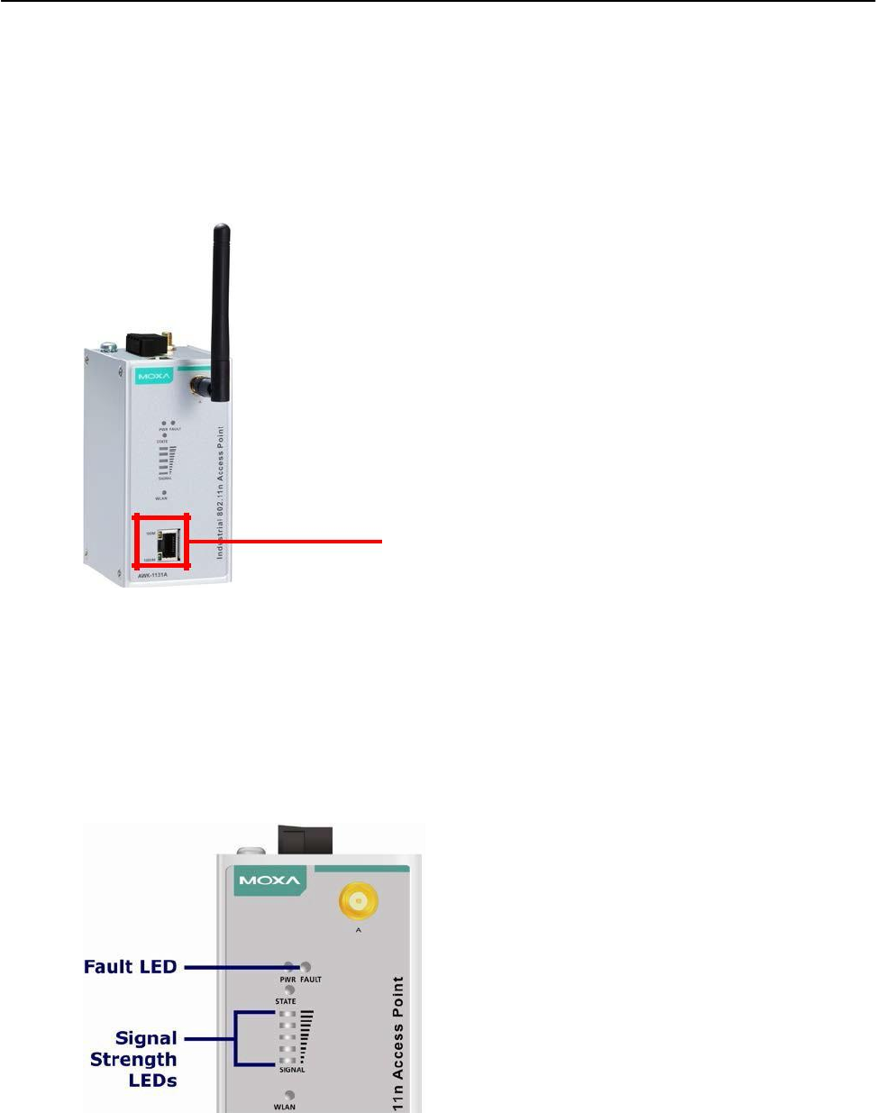
LAN Port
The AWK-1131A comes standard with 1 Gigabit port (Ethernet RJ45). The LAN LED will light up when the
LAN cable is inserted.
RJ45 Ethernet port
LED Indicators
The LEDs on the front panel of the AWK-1131A provide a quick and easy means of determining the
current operational status and wireless settings.
The FAULT LED indicates system failures and user-configured events. If the AWK-1131A cannot retrieve
the IP address from a DHCP server, the FAULT LED will blink at one second intervals. The SIGNAL LEDs
indicate signal strength, and only operate in Client mode.
1-6
AirWorks AWK-1131A Introduction
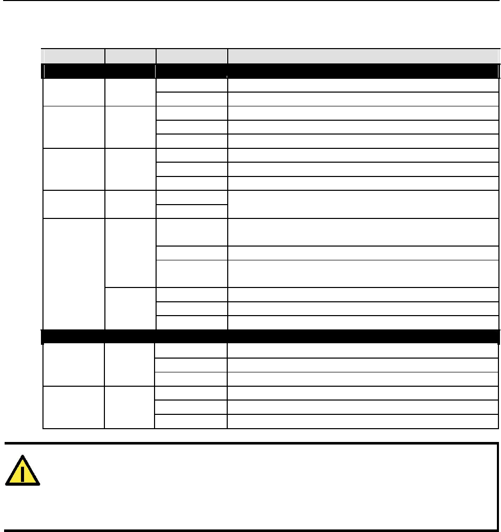
The following table summarizes how to read the device’s wireless settings from the LED displays.
More information is available in Chapter 3 in the “Basic Wireless Settings” section.
LED
Color
State
Description
Front Panel LED Indicators (System)
PWR
Green
On
Power is being supplied from power input 1&2.
Off Power is not being supplied from power input 1&2.
Blink (slow)
Cannot get an IP address from the DHCP server (interval: 1 sec)
FAULT
Red
Blink (fast) IP address conflict (interval: 0.5 sec)
Off Error condition does not exist.
Green/ Green Software Ready
STATE
Green/Blink
The AWK has been located by AWK Search Utility. (interval: 1sec)
Red
Red
Booting error condition
SIGNAL
Green
On
Signal level(for Client mode only)
(5 LEDs)
Off
On
WLAN function is in Client mode and AWK has established a link
with an AP.
Green
Blink
WLAN data communication is run in Client mode
WLAN Off
WLAN is not in Client Mode or AWK has not established a link with
an AP.
On
WLAN function is in AP mode.
Amber
Blink
WLAN’s data communication is run in AP mode
Off WLAN is not in use or not working properly
TP Port(RJ45) LED Indicators (Port Interface)
On
TP port’s 1000Mbps link is active.
1000M
Green
Blink
Data is being transmitted at 1000 Mbps
Off TP port’s 1000Mbps link is inactive.
On
TP port’s 10/100Mbps link is active.
10/100M
Amber
Blink
Data is being transmitted at 10/100 Mbps
Off TP port’s 10/100Mbps link is inactive.
ATTENTION
When the system fails to boot, the LEDs for STATE (Green), FAULT, and WLAN will all light up
simultaneously and blink at one-second intervals. This may be due to improper operation or
uncontrollable issues, such as an unexpected shutdown while updating the firmware. To recover the
firmware, refer to the “Firmware Recovery” section in Chapter 6.
Beeper
The beeper emits two short beeps when the system is ready.
1-7

AirWorks AWK-1131A Introduction
Reset Button
The RESET button is located on the rear panel of the AWK-1131A. You can reboot the AWK-1131A or reset it to
factory default settings by pressing the RESET button with a pointed object such as an unfolded paper clip.
• System reboot: Hold the RESET button down for under 5 seconds and then release.
• Reset to factory default: Hold the RESET button down for over 5 seconds until the STATE LED
starts blinking green. Release the button to reset the AWK-1131A.
1-8

2
2. Getting Started
This chapter explains how to install Moxa’s AirWorks AWK-1131A for the first time, and quickly set up
your wireless network and test whether the connection is running well. The Function Map discussed in the
third section provides a convenient means of determining which functions you need to use.
The following topics are covered in this chapter:
First-time Installation and Configuration
Communication Testing
Function Map
AirWorks AWK-1131A Getting Started
First-time Installation and Configuration
Before installing the AWK-1131A, make sure that all items in the Package Checklist are in the box. You will
need access to a notebook computer or PC equipped with an Ethernet port. The AWK-1131A has a default IP
address that must be used when connecting to the device for the first time.
• Step 1: Select the power source.
The AWK-1131A can be powered by a DC power input. The AWK-1131A will use whichever power
source you choose.
• Step 2: Connect the AWK-1131A to a notebook or PC.
Since the AWK-1131A supports MDI/MDI-X auto-sensing, you can use either a straight-through cable or
crossover cable to connect the AWK-1131A to a computer. The LED indicator on the AWK-1131A’s LAN
port will light up when a connection is established.
• Step 3: Set up the computer’s IP address.
Choose an IP address on the same subnet as the AWK-1131A. Since the AWK-1131A’s default IP
address is 192.168.127.253, and the subnet mask is 255.255.255.0, you should set the IP address
of the computer to 192.168.127.xxx.
NOTE After you select Maintenance Load Factory Default and click the Submit button, the AWK-1131A will be
reset to factory default settings and the IP address will be reset to 192.168.127.253.
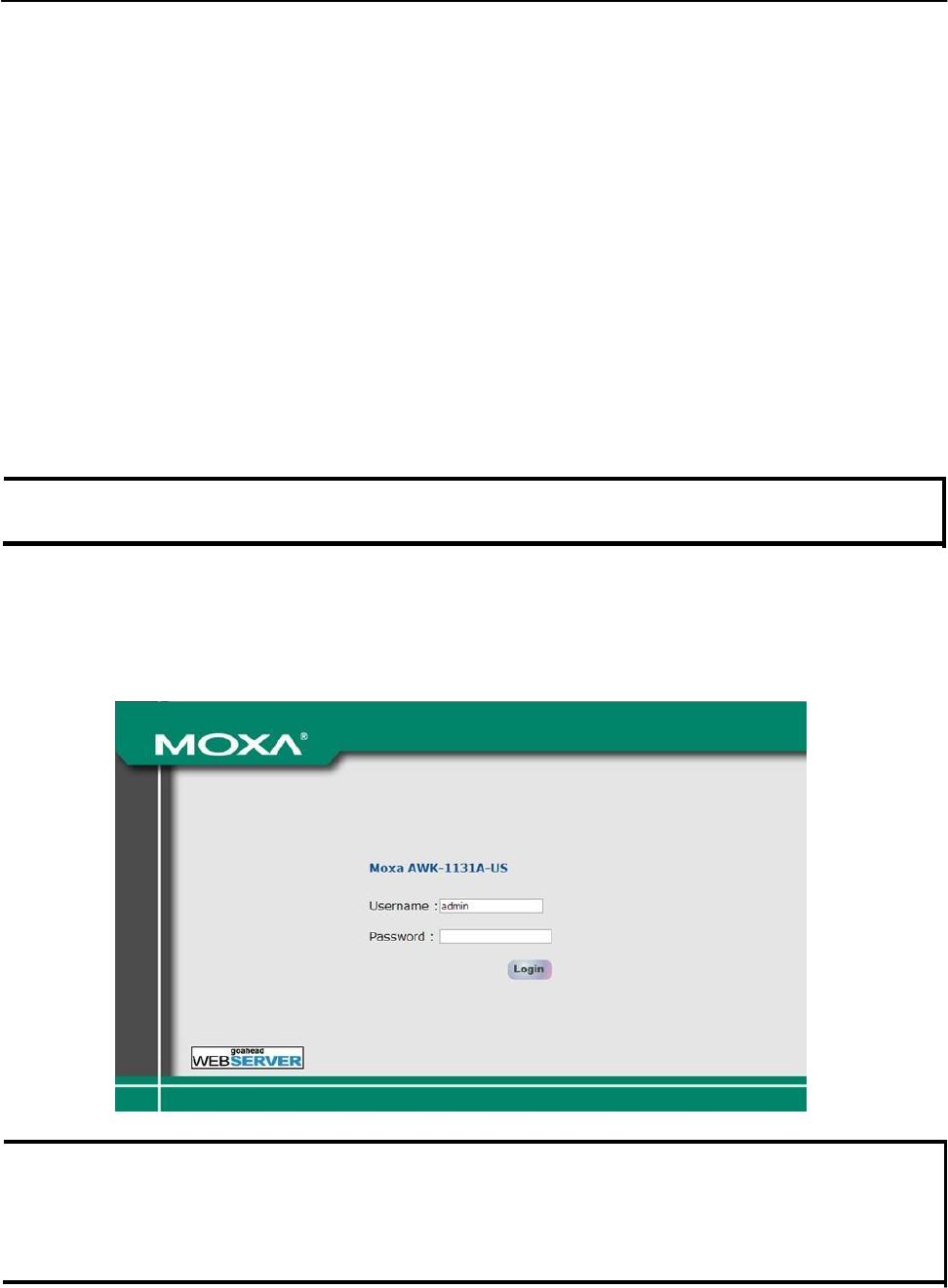
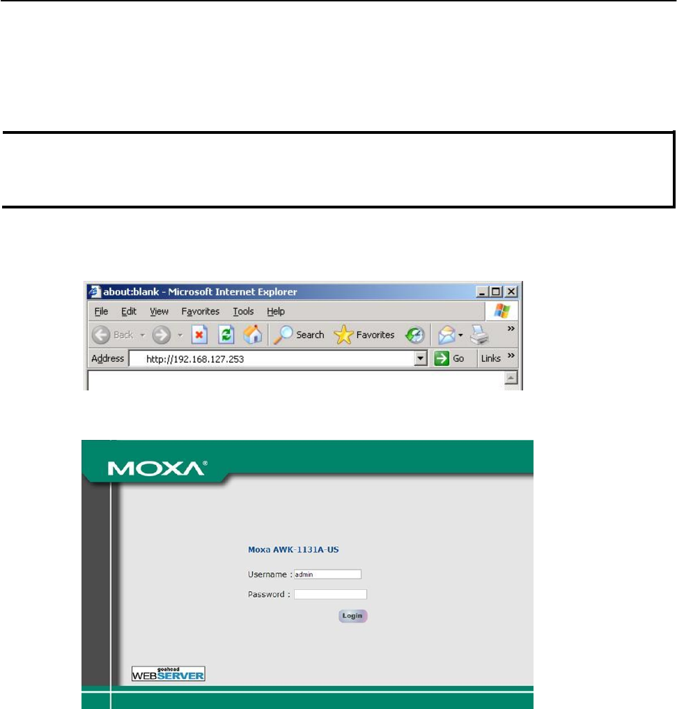
• Step 4: Use the web-based manager to configure the AWK-1131A
Open your computer’s web browser and type http://192.168.127.253 in the address field to access
the homepage of the web-based Network Manager. Before the homepage opens, you will need to enter
the user name and password as shown in the following figure. For first-time configuration, enter the
default user name and password and then click on the Login button:
NOTE Default user name and password:
User Name: admin
Password: root
For security reasons, we strongly recommend changing the default password. To do so, select
Maintenance Password, and then follow the on-screen instructions to change the password.
2-2
AirWorks AWK-1131A Getting Started
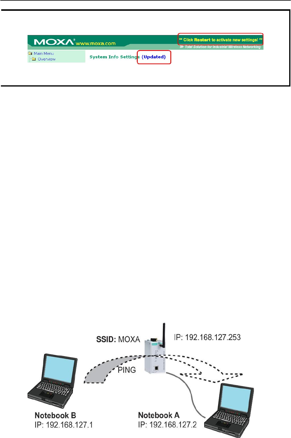
NOTE After you click Submit to apply changes the web page will refresh (Updated) will appear on the page
and a blinking reminder will be shown on the upper-right corner of the web page:
To activate the changes click Restart and then Save and Restart after you change the settings. About
30 seconds are needed for the AWK-1131A to complete the reboot procedure.
• Step 5: Select the AWK-1131A operation mode.
By default, the AWK-1131A’s operation mode is set to AP. You can change to Client mode in Wireless
Settings Basic Wireless Settings. Detailed information about configuring the AWK-1131A’s operation
can be found in Chapter 3.
• Step 6: Test communications.
In the following sections we describe two test methods that can be used to ensure that a
network connection has been established.
Communication Testing
After installing the AWK-1131A you can run a sample test to make sure the AWK-1131A and wireless connection
are functioning normally. Two testing methods are described below. Use the first method if you are using only one
AWK-1131A device, and use the second method if you are using two or more AWK-1131A units.
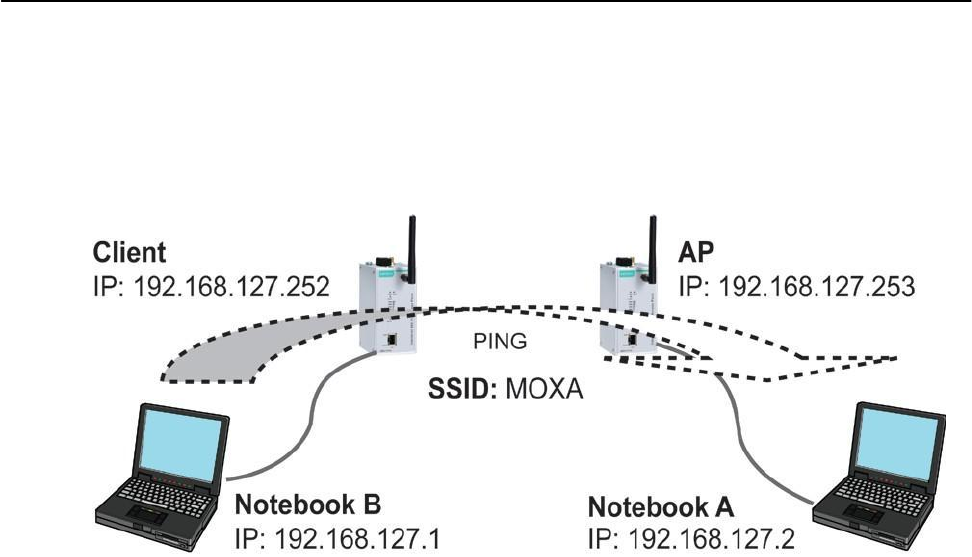
How to Test One AWK-1131A
If you are only using one AWK-1131A, you will need a second notebook computer equipped with a WLAN
card. Configure the WLAN card to connect to the AWK-1131A (NOTE: the default SSID is MOXA), and
change the IP address of the second notebook (Notebook B) so that it is on the same subnet as the first
notebook (Notebook A), which is connected to the AWK-1131A.
After configuring the WLAN card, establish a wireless connection with the AWK-1131A and open a DOS
window on Notebook B. At the prompt, type
ping <IP address of notebook A>
and then press Enter (see the figure below). A “Reply from IP address …” response means the
communication was successful. A “Request timed out.” response means the communication failed. In this
case, recheck the configuration to make sure the connections are correct.
3-2
AirWorks AWK-1131A Getting Started
How to Test Two or More AWK-1131A Units
If you have two or more AWK-1131A units, you will need a second notebook computer (Notebook B)
equipped with an Ethernet port. Use the default settings for the first AWK-1131A connected to notebook A
and change the second or third AWK-1131A connected to notebook B to Client mode, and then configure the
notebooks and AWK-1131A units properly.
After setting up the testing environment, open a DOS window on notebook B. At the prompt, type:
ping <IP address of notebook A>
and then press Enter. A “Reply from IP address …” response means the communication was successful. A
“Request timed out” response means the communication failed. In this case, recheck the configuration to
make sure the connections are correct.
4-2

AirWorks AWK-1131A Getting Started
Function Map
Quick overview of the AWK-1131A’s status
Basic settings for administering the AWK-1131A
Essential settings related to establishing
a wireless network
Advanced features to support additional
network management and secure wired and
wireless communication
Note: These advanced functions are all optional.
Application-oriented device
management functions to set up
events, traps, and reactions via
relay warning, e-mail, and SNMP
notification
Note: These functions are all optional.
Current status information for monitoring
wired/wireless network performance, advanced
services, and device management functions.
Functions for maintaining the AWK-1131A,
and for diagnosing the network.
On-demand functions to support the web-
based console management operation.
5-2

3
3. Web Console Configuration
In this chapter, we explain all aspects of web-based console configuration. Moxa’s easy-to-use management
functions help you set up your AWK-1131A and make it easy to establish and maintain your wireless network.
The following topics are covered in this chapter:
Web Browser Configuration
Overview
Basic Settings
System Info Settings
Network Settings
Time Settings
Wireless Settings
Operation Mode
Basic Wireless Settings
WLAN Security Settings
Advanced Wireless Settings
WLAN Certification Settings (for EAP-TLS
in Client mode only)
Advanced Settings
DHCP Server (for AP mode only)
Packet Filters
SNMP Agent
Link Fault Pass-Through (for Client mode only)
Auto Warning Settings
System Log
Syslog
E-mail
Trap
Status
Wireless Status
Associated Client List (for AP mode only)
DHCP Client List (for AP mode only)
System Log
Power Status
Maintenance
Console Settings
Ping
Firmware Upgrade
Config Import Export
Load Factory Default
Password
Misc. Settings
Save Configuration
Restart
Logout
AirWorks AWK-1131A Web Console Configuration
Web Browser Configuration
Moxa AWK-1131A’s web browser interface provides a convenient way to modify its configuration and
access the built-in monitoring and network administration functions. The recommended web browser is
Microsoft® Internet Explorer 7.0 or 8.0 with JVM (Java Virtual Machine) installed.
NOTE To use the AWK-1131A’s management and monitoring functions from a PC host connected to the same LAN as
the AWK-1131A, you must make sure that the PC host and the AWK-1131A are on the same logical subnet.
The Moxa AWK-1131A’s default IP is 192.168.127.253.
Follow these steps to access the AWK-1131A’s web-based console management interface.
1. Open your web browser (e.g., Internet Explorer) and type the AWK-1131A’s IP address in the address
field. Press Enter to establish the connection.
2. The Web Console Login page will open. Enter the password (default Username = admin; default
Password = root) and then click Login to continue.
3. You may need to wait a few moments for the web page to download to your computer. Note that the
Model name and IP address of your AWK-1131A are both shown in the title bar of the web page. This
information can be used to help you identify multiple AWK-1131A units.
3-2
AirWorks AWK-1131A Web Console Configuration
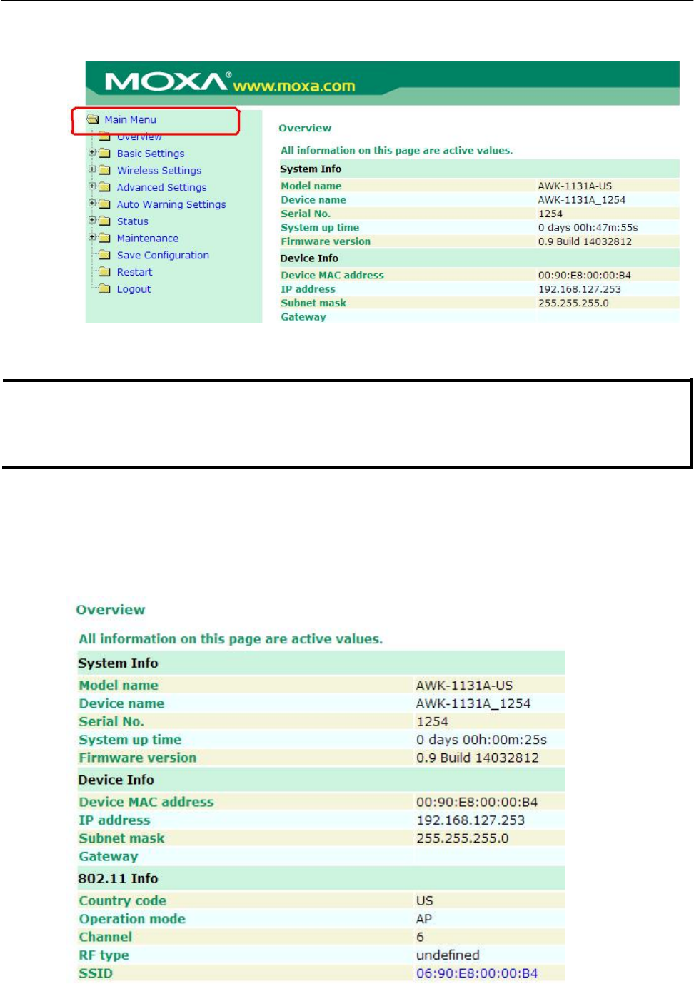
4. Use the menu tree on the left side of the window to open the function pages to access each of
the AWK-1131A’s functions.
In the following paragraphs, we describe each AWK-1131A management function in detail. A quick
overview is available in this manual in the “Function Map” section of Chapter 2.
NOTE The model name of the AWK-1131A is shown as AWK-1131A-XX, where XX indicates the country code. The
country code indicates the AWK-1131A version and which bandwidth it uses. We use AWK-1131A-US as
an example in the following figures. (The country code and model name that appears on your computer
screen may be different than the one shown here.)
Overview
The Overview page summarizes the AWK-1131A’s current status. The information is categorized into
several groups: System info, Device info, and 802.11 info.
3-3
AirWorks AWK-1131A Web Console Configuration
Click on SSID for more detailed 802.11 information, as shown in the following figure.
NOTE The 802.11 info that is displayed may be different for different operation modes. For example,
“Current BSSID” is not available in Client mode, and “Signal strength” is not available in AP mode.
Basic Settings
The Basic Settings group includes the most commonly used settings required by administrators to maintain
and control the AWK-1131A.
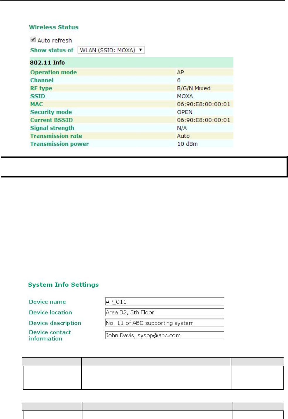
System Info Settings
The System Info items, especially Device name and Device description, are displayed and included on
the Overview page, in SNMP information, and in alarm emails. Setting System Info items makes it easier
to identify the different AWK-1131A units connected to your network.
Device name
Setting Description Factory Default
Max. 31 of characters This option is useful for specifying the role or application of AWK-1131A_<Serial
different AWK-1131A units. No. of this
AWK-1131A>
Device location
Setting Description Factory Default
Max. of 31 characters Specifies the location of different AWK-1131A units. None
3-4
AirWorks AWK-1131A Web Console Configuration
Device description
Setting Description Factory Default
Max. of 31 characters Use this space to record a more detailed description of the None
AWK-1131A
Device contact information
Setting Description Factory Default
Max. of 31 characters
Provides information about whom to contact in order to resolve
None
problems. Use this space to record contact information of the
person responsible for maintaining this AWK-1131A.
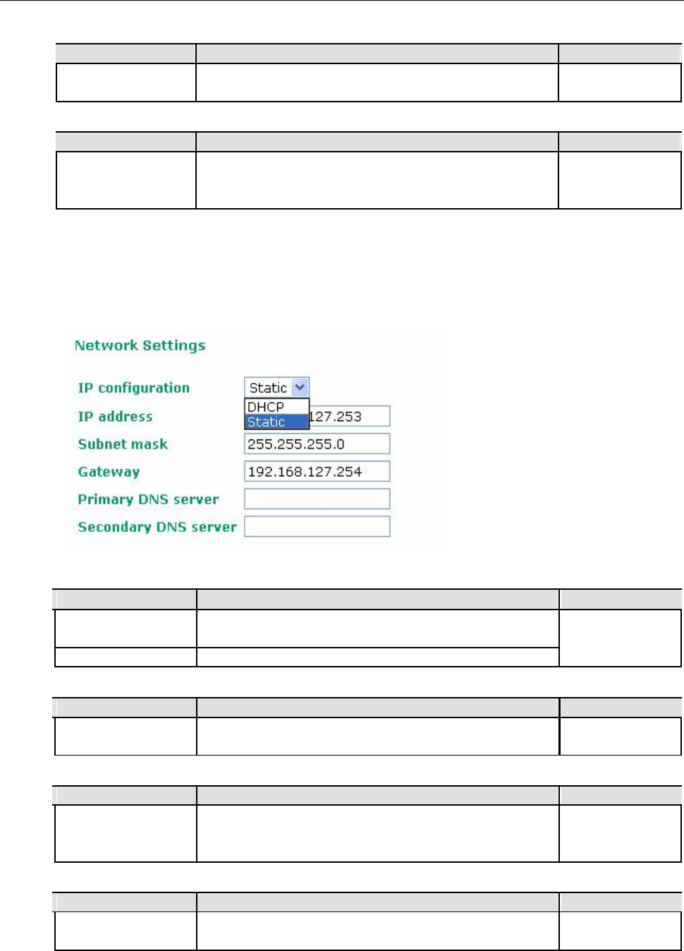
Network Settings
The Network Settings configuration panel allows you to modify the usual TCP/IP network parameters.
An explanation of each configuration item is given below.
IP configuration
Setting Description Factory Default
DHCP
The AWK-1131A’s IP address will be assigned automatically by
Static
the network’s DHCP server
Static Set up the AWK-1131A’s IP address manually.
IP address
Setting Description Factory Default
AWK-1131A’s IP Identifies the AWK-1131A on a TCP/IP network. 192.168.127.253
address
Subnet mask
Setting Description Factory Default
AWK-1131A’s subnet Identifies the type of network to which the AWK-1131A is 255.255.255.0
mask connected (e.g., 255.255.0.0 for a Class B network, or
255.255.255.0 for a Class C network).
Gateway
Setting Description Factory Default
AWK-1131A’s default
The IP address of the router that connects the LAN to an outside
None
gateway network.
3-5
AirWorks AWK-1131A Web Console Configuration
Primary/ Secondary DNS server
Setting Description Factory Default
IP address of the The IP address of the DNS Server used by your network. After None
Primary/Secondary entering the DNS Server’s IP address, you can input the
DNS server AWK-1131A’s URL (e.g., http://ap11.abc.com) in your
browser’s address field instead of entering the IP address. The
Secondary DNS server will be used if the Primary DNS server
fails to connect.
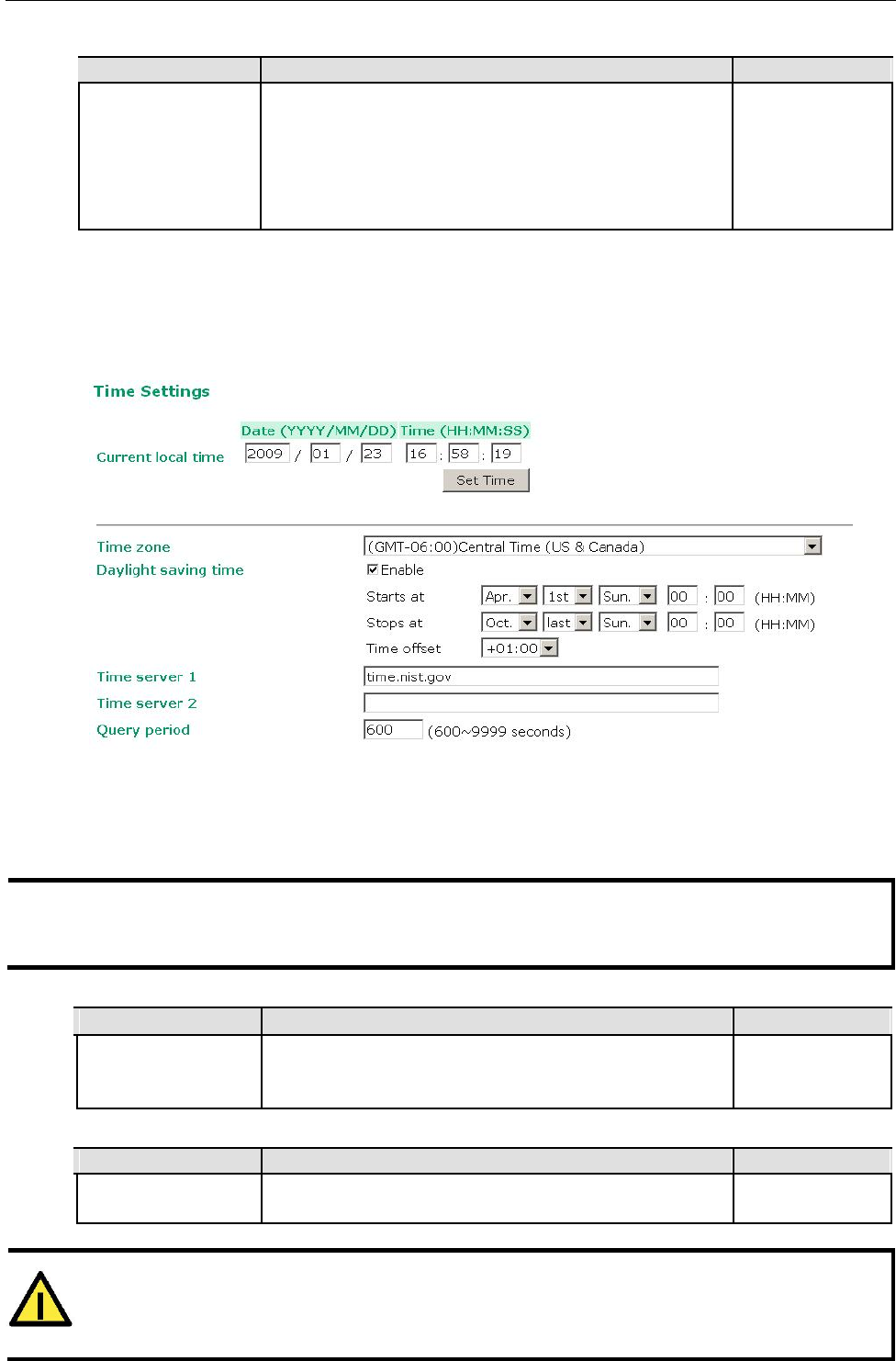
Time Settings
The AWK-1131A has a time calibration function based on information from an NTP server or user specified
Date and Time information. Functions such as Auto warning can add real-time information to the message.
The Current local time shows the AWK-1131A’s system time when you open this web page. You can click
on the Set Time button to activate the updated date and time parameters. An “(Updated)” string will
appear to indicate that the change is complete. Local time settings will be immediately activated in the
system without running Save and Restart.
NOTE The AWK-1131A has a built-in real time clock (RTC). We strongly recommend that users update the Local
time for the AWK-1131A after the initial setup or a long-term shutdown, especially when the network
does not have an Internet connection for accessing the NTP server or there is no NTP server on the LAN.
Current local time
Setting Description Factory Default
User adjustable time The date and time parameters allow configuration of the local None
time, with immediate activation.
Use 24-hour format: yyyy/mm/dd hh:mm:ss
Time zone
Setting Description Factory Default
User selectable time The time zone setting allows conversion from GMT (Greenwich GMT (Greenwich
zone Mean Time) to local time. Mean Time)
ATTENTION
Changing the time zone will automatically adjust the Current local time. You should configure the
Time zone before setting the Current local time.
3-6
AirWorks AWK-1131A Web Console Configuration
Daylight saving time
Setting Description Factory Default
Enable/ Disable Daylight saving time (also know as DST or summer time) Disable
involves advancing clocks (usually 1 hour) during the summer
time to provide an extra hour of daylight in the afternoon.
When Daylight saving time is enabled, the following parameters will be shown:
• Starts at: The date that daylight saving time begins.
• Stops at: The date that daylight saving time ends.
• Time offset: Indicates how many hours forward the clock should be advanced.
Time server 1/2
Setting Description Factory Default
IP/Name of Time
IP or Domain name of the NTP time server. The 2nd NTP server
time.nist.gov
Server 1/2 will be used if the 1st NTP server fails to connect.
Query period
Setting Description Factory Default
Query period time
This parameter determines how often the time is updated from
600 (seconds)
(1 to 9999 seconds) the NTP server.
Wireless Settings
The essential settings for wireless networks are presented in this function group. Settings must be properly
set before establishing your wireless network. Familiarize yourself with the following terms before starting
the configuration process:
AP: In a wireless local area network (WLAN), an access point is a station that transmits and receives data.
Client: When the AWK-1131A is configured for Client mode, it can be used as an Ethernet-to-wireless (or
LAN-to-WLAN) network adaptor. For example, a notebook computer equipped with an Ethernet adaptor but
no wireless card can be connected to this device with an Ethernet cable to provide wireless connectivity to
another AP.
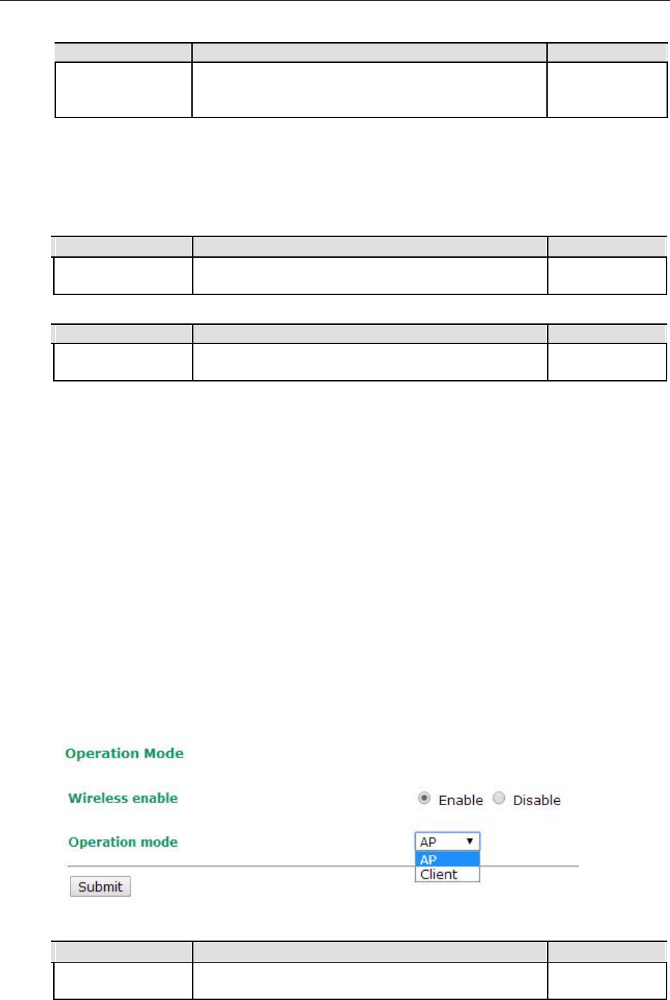
Operation Mode
The AWK-1131A supports four main operation modes—AP, Client—each of which plays a distinct role on
the wireless network.
Wireless Enable
Setting Description Factory Default
Enable/Disable
The RF (Radio Frequency) module can be manually turned on or
Enable
off. This function is available in AP operation mode only.
3-7
AirWorks AWK-1131A Web Console Configuration
Operation Mode
Setting Description Factory Default
AP The AWK-1131A plays the role of wireless Access Point AP
Client The AWK-1131A plays the role of wireless Client
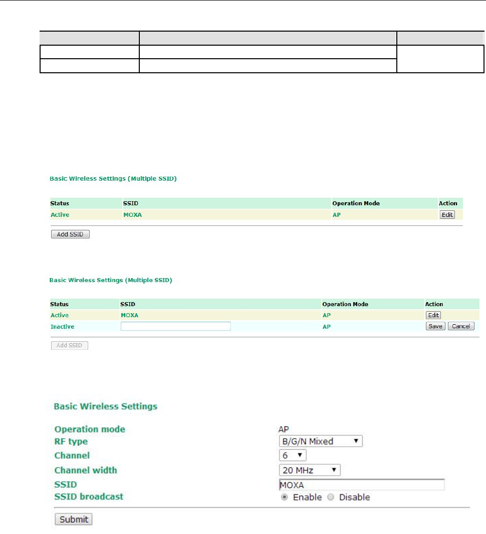
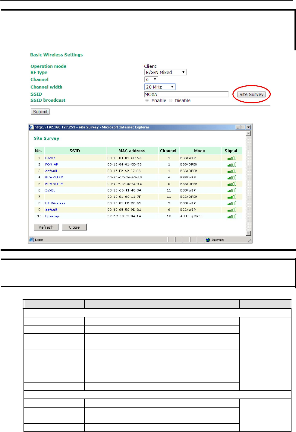
Basic Wireless Settings
The “WLAN Basic Setting Selection” panel is used to add and edit SSIDs. An SSID is a unique identifier that
wireless networking devices use to establish and maintain wireless connectivity. Multiple access points on a
network or sub-network can use the same SSIDs.
Click on Add SSID to create more SSIDs.
Click on Edit to assign different configuration settings to each SSID. The configuration panel appears
as follows:
3-8
AirWorks AWK-1131A Web Console Configuration
NOTE When you switch to Client mode, a Site Survey button will be available on the Basic Wireless Settings
panel. Click the “Site Survey” button to view information about available APs, as shown in the following
figure. You can click on the SSID of an entity and bring the value of its SSID onto the SSID field of the Basic
Wireless Settings page. Click the Refresh button to re-scan and update the table.
NOTE If the Gateway field in Basic Settings Network Settings is empty, a warning message will appear,
reminding you to set the default gateway when Client mode is enabled. You can ignore this message if you
are only planning a local network and packets will not be sent outside the network.
RF type
Setting Description Factory Default
2.4 GHz
B Only supports the IEEE 802.11b standard B/G/N Mixed
G Only supports the IEEE 802.11g standard
B/G Mixed
Supports IEEE 802.11b/g standards, but 802.11g may operate
at a slower speed if when 802.11b clients are on the network
G/N Mixed
Supports IEEE 802.11g/n standards, but 802.11n may operate
at a slower speed if 802.11g clients are on the network
B/G/N Mixed Supports IEEE 802.11b/g/n standards, but 802.11g/n may
operate at a slower speed if 802.11b clients are on the network
N Only (2.4GHz) Only supports the 2.4 GHz IEEE 802.11n standard
5 GHz
A Only supports the IEEE 802.11a standard
A/N Mixed
Supports IEEE 802.11a/n standards, but 802.11n may operate
at a slower speed if 802.11a clients are on the network
N Only (5GHz) Only supports the 5 GHz IEEE 802.11n standard
3-9
AirWorks AWK-1131A Web Console Configuration
NOTE In legacy mode (802.11a/b/g) only antenna port “A” can work for transmitting and receiving. To protect the
connectors and the RF module, all radio ports should be terminated by either an antenna or a terminator. The use
of the resistive terminator for terminating the unused antenna port is strongly recommended.
Channel (for AP mode only)
Setting Description Factory Default
Available channels vary The AWK-1131A plays the role of wireless AP. 6 (in B/G/N Mixed
with RF type mode)
Channel Width (for any 802.11N RF type only)
Setting Description Factory Default
20 MHz Select your channel width, If you are not sure which option to 20 MHz
use, select 20/ 40MHz (Auto)
20/40 MHz
Channel bonding
If 20/40 MHz only is the Channel Width setting, this channel bonding will auto set the channel based on
your channel setting.
SSID
Setting Description Factory Default
Max. of 31 characters
The SSID of a client and the SSID of the AP must be identical for
MOXA
the client and AP to be able to communicate with each other.
SSID broadcast (for AP mode only)
Setting Description Factory Default
Enable/ Disable SSID can be broadcast or not Enable
NOTE The AWK-1131A-JP (for Japanese frequency bands) only connects SSID-hidden APs for IEEE 802.11a
channels, and IEEE 802.11g/n channels 1 to 11. The AWK-1131A-EU (for European frequency bands) only
connects SSID-hidden APs for IEEE 802.11b/g/n channels.
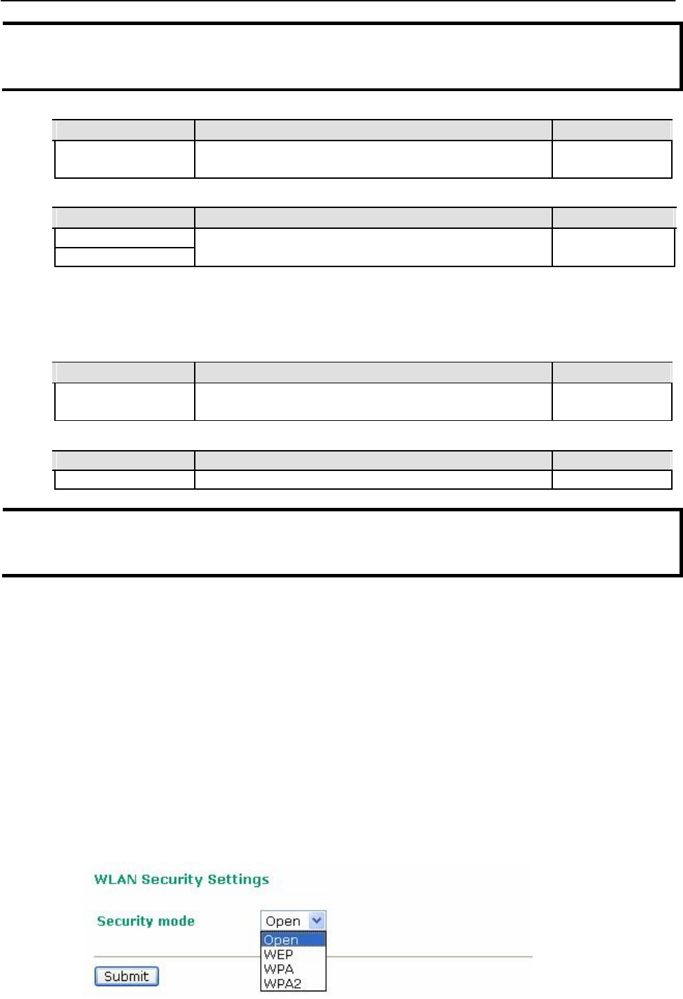
WLAN Security Settings
The AWK-1131A provides four standardized wireless security modes: Open, WEP (Wired Equivalent
Privacy), WPA (Wi-Fi Protected Access), and WPA2. Several security modes are available in the AWK-
1131A by selecting Security mode and WPA type:
• Open: No authentication, no data encryption.
• WEP: Static WEP (Wired Equivalent Privacy) keys must be configured manually.
• WPA/WPA2-Personal: Also known as WPA/WPA2-PSK. You will need to specify the Pre-Shared Key in
the Passphrase field, which will be used by the TKIP or AES engine as a master key to generate keys
that actually encrypt outgoing packets and decrypt incoming packets.
WPA/WPA2-Enterprise: Also called WPA/WPA2-EAP (Extensible Authentication Protocol). In addition
to device-based authentication, WPA/WPA2-Enterprise enables user-based authentication via
IEEE802.1X. The AWK-1131A can support three EAP methods: EAP-TLS, EAP-TTLS, and EAP-PEAP.
3-10
AirWorks AWK-1131A Web Console Configuration
Security mode
Setting Description Factory Default
Open No authentication Open
WEP Static WEP is used
WPA WPA is used
WPA2 Fully supports IEEE802.11i with “TKIP/AES + 802.1X”
Open
For security reasons, you should NOT set security mode to Open System, since authentication and
data encryption are NOT performed in Open System mode.
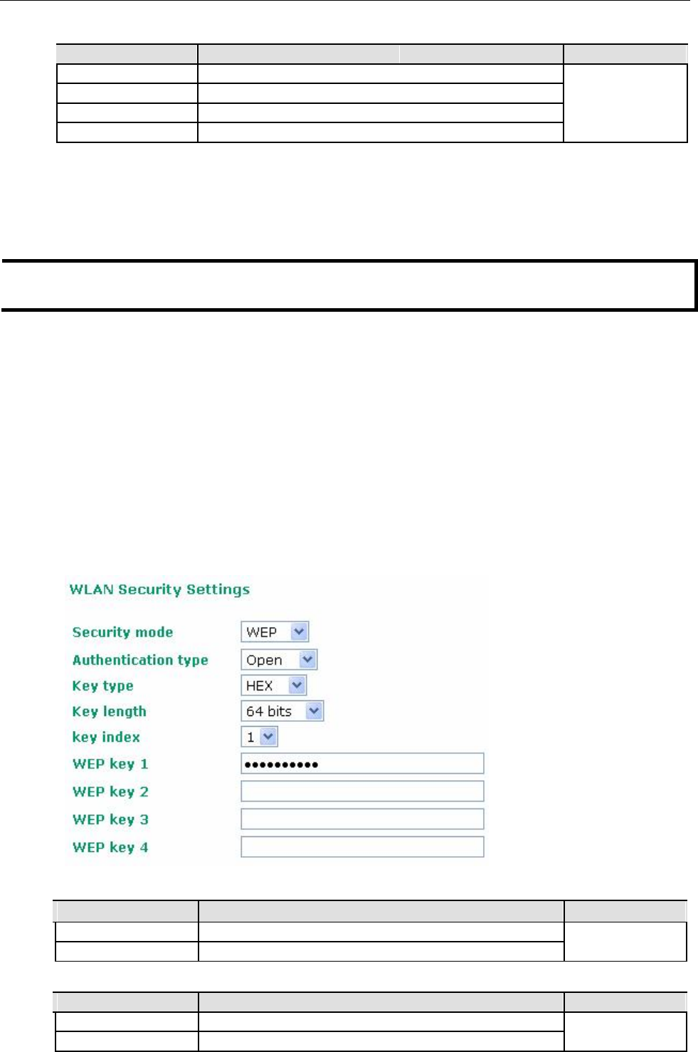
WEP (only for legacy mode)
NOTE Moxa includes WEP security mode only for legacy purposes. WEP is highly insecure and is considered fully
deprecated by the Wi-Fi alliance. We do not recommend the use of WEP security under any circumstances.
According to the IEEE802.11 standard, WEP can be used for authentication and data encryption to maintain
confidentiality. Shared (or Shared Key) authentication type is used if WEP authentication and data
encryption are both needed. Normally, Open (or Open System) authentication type is used when WEP
data encryption is run with authentication.
When WEP is enabled as a security mode, the length of a key (so-called WEP seed) can be specified as 64/128
bits, which is actually a 40/104-bit secret key with a 24-bit initialization vector. The AWK-1131A provides 4
entities of WEP key settings that can be selected to use with Key index. The selected key setting specifies the key
to be used as a send-key for encrypting traffic from the AP side to the wireless client side. All 4 WEP keys are used
as receive-keys to decrypt traffic from the wireless client side to the AP side.
The WEP key can be presented in two Key types, HEX and ASCII. Each ASCII character has 8 bits, so a
40-bit (or 64-bit) WEP key contains 5 characters, and a 104-bit (or 128-bit) key has 13 characters. In hex,
each character uses 4 bits, so a 40-bit key has 10 hex characters, and a 128-bit key has 26 characters.
Authentication type
Setting Description Factory Default
Open Data encryption is enabled, but without authentication Open
Shared Data encryption and authentication are both enabled.
Key type
Setting Description Factory Default
HEX Specifies WEP keys in hex-decimal number form HEX
ASCII Specifies WEP keys in ASCII form
3-11
AirWorks AWK-1131A Web Console Configuration
Key length
Setting Description Factory Default
64 bits Uses 40-bit secret keys with 24-bit initialization vector 64 bits
128 bits Uses 104-bit secret key with 24-bit initialization vector
Key index
Setting Description Factory Default
1-4 Specifies which WEP key is used Open
WEP key 1-4
Setting Description Factory Default
ASCII type:
A string that can be used as a WEP seed for the RC4 encryption
None
64 bits: 5 chars engine.
128 bits: 13chars
HEX type:
64 bits: 10 hex chars
128 bits: 26 hex chars
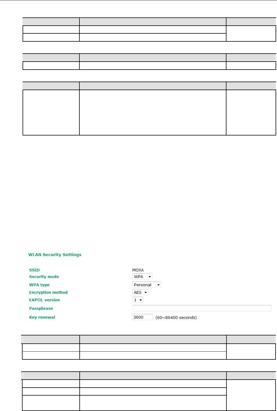
WPA/WPA2-Personal
WPA (Wi-Fi Protected Access) and WPA2 represent significant improvements over the WEP encryption
method. WPA is a security standard based on 802.11i draft 3, while WPA2 is based on the fully ratified
version of 802.11i. The initial vector is transmitted, encrypted, and enhanced with its 48 bits, twice as long
as WEP. The key is regularly changed so that true session is secured.
Even though AES encryption is only included in the WPA2 standard, it is widely available in the WPA security
mode of some wireless APs and clients as well. The AWK-1131A also supports AES algorithms in WPA and
WPA2 for better compatibility.
Personal versions of WPA/WPA2, also know as WPA/WPA-PSK (Pre-Shared Key), provide a simple way of
encrypting a wireless connection for high confidentiality. A Passphrase is used as a basis for encryption methods
(or cipher types) in a WLAN connection. The passphrases should be complicated and as long as possible. There
must be at least 8 ASCII characters in the Passphrase, and it could go up to 63. For security reasons, this
passphrase should only be disclosed to users who need it, and it should be changed regularly.
WPA type
Setting Description Factory Default
Personal Provides Pre-Shared Key-enabled WPA and WPA2 Personal
Enterprise Provides enterprise-level security for WPA and WPA2
Encryption method
Setting Description Factory Default
TKIP** Temporal Key Integrity Protocol is enabled AES
AES Advance Encryption System is enabled
Mixed* Provides TKIP broadcast key and TKIP+AES unicast key for
some legacy AP clients. This option is rarely used.
** This option is only available with 802.11a/b/g standard
* This option is available for legacy mode in AP only, and does not support AES-enabled clients.
3-12
AirWorks AWK-1131A Web Console Configuration
Passphrase
Setting Description Factory Default
8 to 63 characters Master key to generate keys for encryption and decryption None
Key renewal (for AP mode only)
Setting Description Factory Default
60 to 86400 seconds Specifies the time period of group key renewal 3600 (seconds)
(1 minute to 1 day)
NOTE The key renewal value dictates how often the wireless AP encryption keys should be changed. The
security level is generally higher if you set the key renewal value to a shorter number, which forces the
encryption keys to be changed more frequently. The default value is 3600 seconds (6 minutes). Longer
time periods can be considered if the line is not very busy.
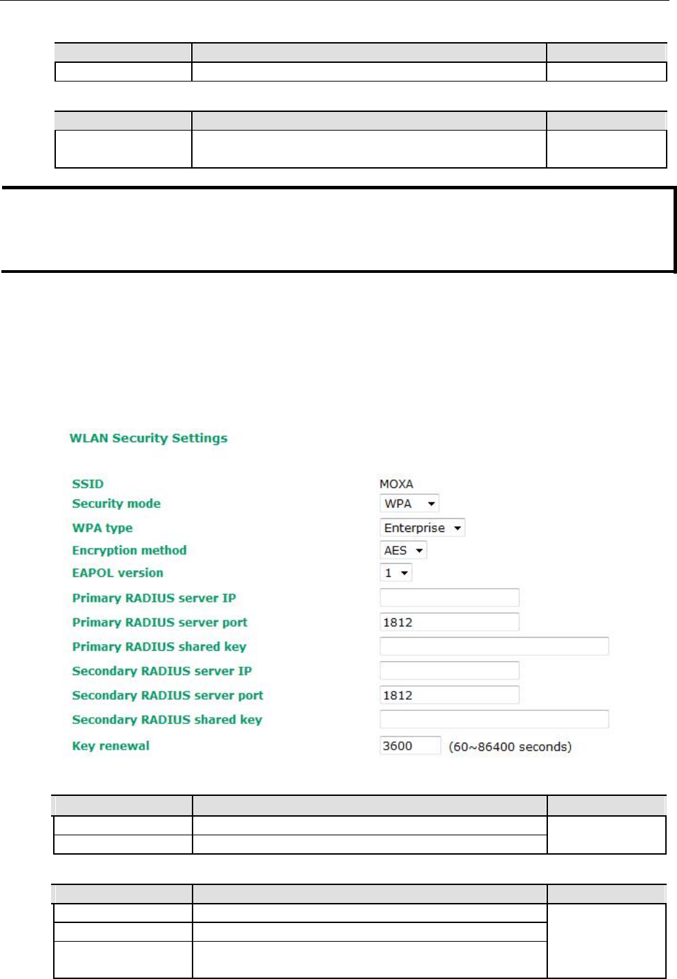
WPA/WPA2-Enterprise (for AP mode)
By setting WPA type to Enterprise, you can use EAP (Extensible Authentication Protocol), a framework
authentication protocol used by 802.1X to provide network authentication. In these Enterprise-level
security modes, a back-end RADIUS (Remote Authentication Dial-In User Service) server is needed if IEEE
802.1X functionality is enabled in WPA /WPA2. The IEEE 802.1X protocol also offers the possibility of
carrying out an efficient connection authentication on a large-scale network. It is not necessary to
exchange keys or passphrases.
WPA type
Setting Description Factory Default
Personal Provides Pre-Shared Key-enabled WPA and WPA2 Personal
Enterprise Provides enterprise-level security for WPA and WPA2
Encryption method
Setting Description Factory Default
TKIP** Temporal Key Integrity Protocol is enabled AES
AES Advance Encryption System is enabled
Mixed* Provides TKIP broadcast key and TKIP+AES unicast key for
some legacy AP clients. This option is rarely used.
** This option is only available with 802.11a/b/g standard
* This option is available for legacy mode in AP only, and does not support AES-enabled clients.
3-13
AirWorks AWK-1131A Web Console Configuration
Primary/Secondary RADIUS server IP
Setting Description Factory Default
The IP address of Specifies the delegated RADIUS server for EAP None
RADIUS server
Primary/Secondary RADIUS port
Setting Description Factory Default
Port number Specifies the port number of the delegated RADIUS server 1812
Primary/ Secondary RADIUS shared key
Setting Description Factory Default
Max. of 31 characters The secret key shared between AP and RADIUS server None
Key renewal
Setting Description Factory Default
60 to 86400 seconds Specifies the time period of group key renewal 3600 (seconds)
(1 minute to 1 year)
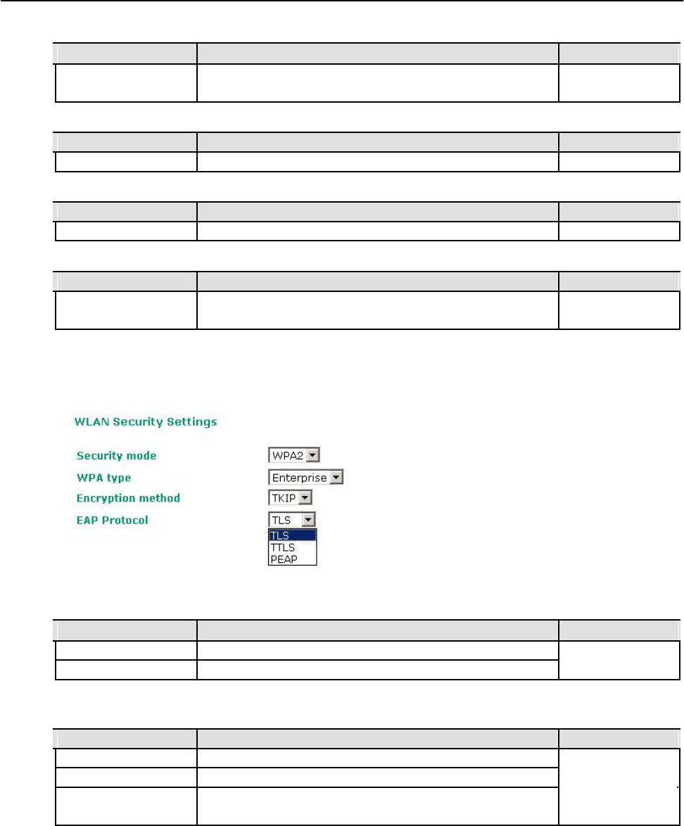
WPA/WPA2-Enterprise (for Client mode)
When used as a client, the AWK-1131A can support three EAP methods (or EAP protocols): EAP-TLS,
EAP-TTLS, and EAP-PEAP, corresponding to WPA/WPA-Enterprise settings on the AP side.
Encryption method
Setting Description Factory Default
TKIP** Temporal Key Integrity Protocol is enabled TKIP
AES Advance Encryption System is enabled
**This option is only available with 802.11a/b/g standard.
EAP Protocol
Setting Description Factory Default
TLS Specifies Transport Layer Security protocol TLS
TTLS Specifies Tunneled Transport Layer Security
PEAP Specifies Protected Extensible Authentication Protocol, or
Protected EAP
Before choosing the EAP protocol for your WPA/WPA2-Enterpise settings on the client end, please contact
the network administrator to make sure the system supports the protocol on the AP end. Detailed
information on these three popular EAP protocols is presented in the following sections.
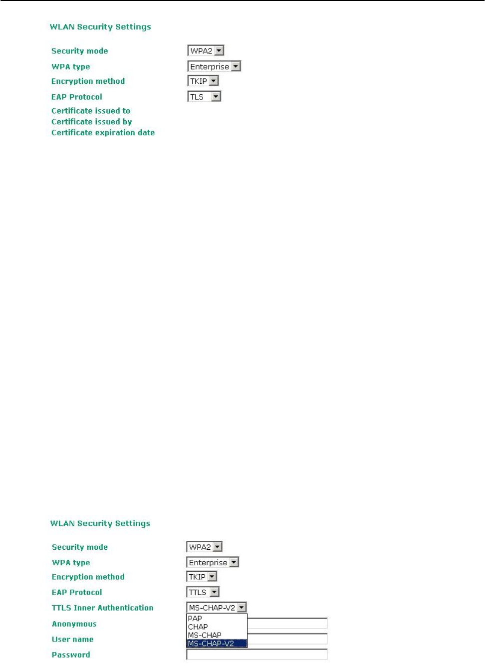
EAP-TLS
TLS is the standards-based successor to Secure Socket Layer (SSL). It can establish a trusted
communication channel over a distrusted network. TLS provides mutual authentication through certificate
exchange. EAP-TLS is also secure to use. You are required to submit a digital certificate to the
authentication server for validation, but the authentication server must also supply a certificate.
You can use Basic Wireless Settings WLAN Certificate Settings to import your WLAN certificate and
enable EAP-TLS on the client end.
3-14
AirWorks AWK-1131A Web Console Configuration
You can check the current certificate status in Current Status if it is available.
• Certificate issued to: Shows the certificate user
• Certificate issued by: Shows the certificate issuer
• Certificate expiration date: Indicates when the certificate has expired
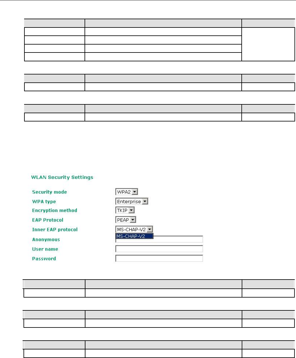
EAP-TTLS
It is usually much easier to re-use existing authentication systems, such as a Windows domain or Active
Directory, LDAP directory, or Kerberos realm, rather than creating a parallel authentication system. As a
result, TTLS (Tunneled TLS) and PEAP (Protected EAP) are used to support the use of so-called “legacy
authentication methods.”
TTLS and PEAP work in a similar way. First, they establish a TLS tunnel (EAP-TLS for example), and
validate whether the network is trustworthy with digital certificates on the authentication server. This step
establishes a tunnel that protects the next step (or “inner” authentication), and consequently is sometimes
referred to as “outer” authentication. The TLS tunnel is then used to encrypt an older authentication
protocol that authenticates the user for the network.
As you can see, digital certificates are still needed for outer authentication in a simplified form. Only a
small number of certificates are required, which can be generated by a small certificate authority.
Certificate reduction makes TTLS and PEAP much more popular than EAP-TLS.
The AWK-1131A provides some non-cryptographic EAP methods, including PAP, CHAP, MS-CHAP, and
MS-CHAP-V2. These EAP methods are not recommended for direct use on wireless networks. However,
they may be useful as inner authentication methods with TTLS and PEAP.
Because the inner and outer authentications can use distinct user names in TTLS and PEAP, you can use an
anonymous user name for the outer authentication, with the true user name only shown through the
encrypted channel. Keep in mind that not all client software supports anonymous alteration. Confirm this
with the network administrator before you enable identity hiding in TTLS and PEAP.
3-15
AirWorks AWK-1131A Web Console Configuration
TTL Inner Authentication
Setting Description Factory Default
PAP Password Authentication Protocol is used MS-CHAP-V2
CHAP Challenge Handshake Authentication Protocol is used
MS-CHAP Microsoft CHAP is used
MS-CHAP-V2 Microsoft CHAP version 2 is used
Anonymous
Setting Description Factory Default
Max. of 31 characters A distinct name used for outer authentication None
User name & Password
Setting Description Factory Default
User name and password used in inner authentication None
PEAP
There are a few differences in the TTLS and PEAP inner authentication procedures. TTLS uses the encrypted
channel to exchange attribute-value pairs (AVPs), while PEAP uses the encrypted channel to start a second
EAP exchange inside of the tunnel. The AWK-1131A provides MS-CHAP-V2 merely as an EAP method for
inner authentication.
Inner EAP protocol
Setting Description Factory Default
MS-CHAP-V2 Microsoft CHAP version 2 is used MS-CHAP-V2
Anonymous
Setting Description Factory Default
Max. of 31 characters A distinct name used for outer authentication None
User name & Password
Setting Description Factory Default
User name and password used in inner authentication None
3-16
AirWorks AWK-1131A Web Console Configuration
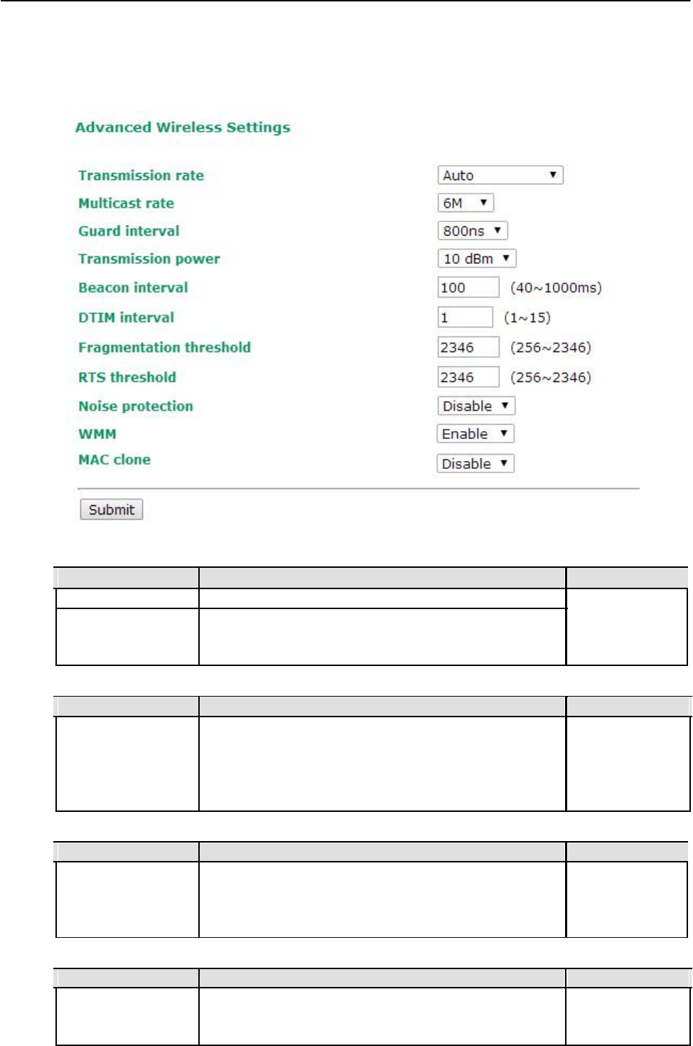
Advanced Wireless Settings
Additional wireless-related parameters are presented in this section to help you set up your wireless
network in detail.
Transmission Rate
Setting Description Factory Default
Auto
The AWK-1131A senses and adjusts the data rate automatically
Auto
Available rates Users can manually select a target transmission data rate but
does't support when RF type are G/N Mixed, B/G/N Mixed,
A/N Mixed and N only.
Multicast Rate
Setting Description Factory Default
Available rates You can set a fixed multicast rate for the transmission of 6M
broadcast and multicast packets on a per-radio basis. This
parameter can be useful in an environment where multicast
video streaming is occurring in the wireless medium, providing
the wireless clients are capable of handling the configured rate
Guarding Interval
Setting Description Factory Default
Guarding Interval Guarding interval is used to ensure that distinct transmissions 800ns.
do not interfere with one another. You can select the guarding
interval manually for Wireless-N connections. The two options
are Short (400ns) and Long (800ns).
Transmission Power
Setting Description Factory Default
Available power Users can manually select a target power to mask max output 10
power. Because different transmission rate would have it own
max output power, please reference product datasheet.
3-17

AirWorks AWK-1131A Web Console Configuration
Beacon Interval (for AP mode only)
Setting Description Factory Default
Beacon Interval Indicates the frequency interval of the beacon 100 (ms)
(40 to 1000 ms)
DTIM Interval (for AP mode only)
Setting Description Factory Default
Data Beacon Rate Indicates how often the AWK-1131A sends out a Delivery 1
(1 to 15) Traffic Indication Message
Fragmentation threshold
Setting Description Factory Default
Fragment Length Specifies the maximum size a data packet before splitting and 2346
(256 to 2346) creating another new packet
RTS threshold
Setting Description Factory Default
RTS/CTS Threshold Determines how large a packet can be before the Access Point 2346
(256 to 2346) coordinates transmission and reception to ensure efficient
communication
NOTE You can refer to the related glossaries in Chapter 5 for detailed information about the above-mentioned settings.
By setting these parameters properly, you can better tune the performance of your wireless network.
Noise protection
Setting Description Factory Default
Enable/Disable
Adjusts the interference coping capability of the wireless signal.
Disable
If you have some noisy areas, then give this a swing and see if
you get an improvement.
WMM
Setting Description Factory Default
Enable/Disable WMM is a QoS standard for WLAN traffic. Voice and video data Enable
will be given priority bandwidth when enabled with WMM
supported wireless clients.
Note: WMM will always be enabled under 802.11n mode.
MAC clone
Setting Description Factory Default
Enable/Disable When AWK-1131A becomes an a Client, it would replace the Disable
device's MAC address what is connected behind AWK-1131A to
do communication. In some application would be asked to use
specific MAC address to do communication, then you could use
this function to clone device's MAC address on AWK-1131A to
avoid replacement of MAC address.
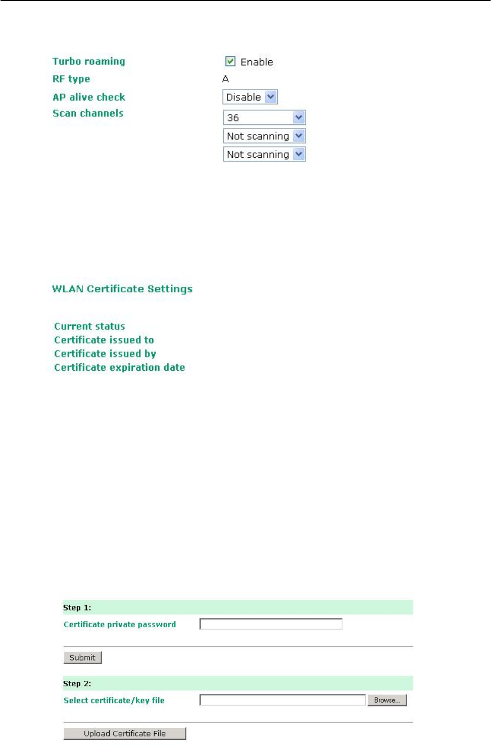
Turbo Roaming (for Client mode only)
Setting Description Factory Default
Enable/ Disable Moxa’s Turbo Roaming can enable rapid handover when the Disable
AWK-1131A, as a client, roams among a group of APs.
When Turbo Roaming is enabled, the RF type, AP alive check, and Scan channels will be shown as follows. RF type
shows the current RF type that this client is using. AP alive check will check if the AP connection is still available.
When this function is enabled, a check will be done every 10 ms. You can set up Scan channels for the APs among
which this client is going to roam. There are three Scan channels available. Note that the Scan
3-18
AirWorks AWK-1131A Web Console Configuration
channels may need to be modified when the RF type is changed. (For example, channel 36 is not available in
B, G, N or B/G/N Mix mode.)
WLAN Certification Settings (for EAP-TLS in Client mode only)
When EAP-TLS is used, a WLAN Certificate will be required at the client end to support WPA/WPA2-
Enterprise. The AWK-1131A can support the PKCS #12, also known as Personal Information Exchange
Syntax Standard, certificate formats that define file formats commonly used to store private keys with
accompanying public key certificates, protected with a password-based symmetric key.
Current Status displays information for the current WLAN certificate, which has been imported into the
AWK-1131A. Nothing will be shown if a certificate is not available.
Certificate issued to: Shows the certificate user
Certificate issued by: Shows the certificate issuer
Certificate expiration date: Indicates when the certificate has expired
You can import a new WLAN certificate in Import WLAN Certificate by following these steps, in order:
1. Input the corresponding password (or key) in the Certificate private password field and then
click Submit to set the password.
2. The password will be displayed in the Certificate private password field. Click on the Browse button
in Select certificate/key file and select the certificate file.
3. Click Upload Certificate File to import the certificate file. If the import succeeds, you can see
the information uploaded in Current Certificate. If it fails, you may need to return to step 1 to
set the password correctly and then import the certificate file again.
3-19
AirWorks AWK-1131A Web Console Configuration
NOTE The WLAN certificate will remain after the AWK-1131A reboots. Even though it is expired, it can still be
seen on the Current Certificate.
Advanced Settings
Several advanced functions are available to increase the functionality of your AWK-1131A and wireless
network system. The DHCP server helps you deploy wireless clients efficiently. Packet filters provide
security mechanisms, such as firewalls, in different network layers. Moreover, SNMP support can make
network management easier.
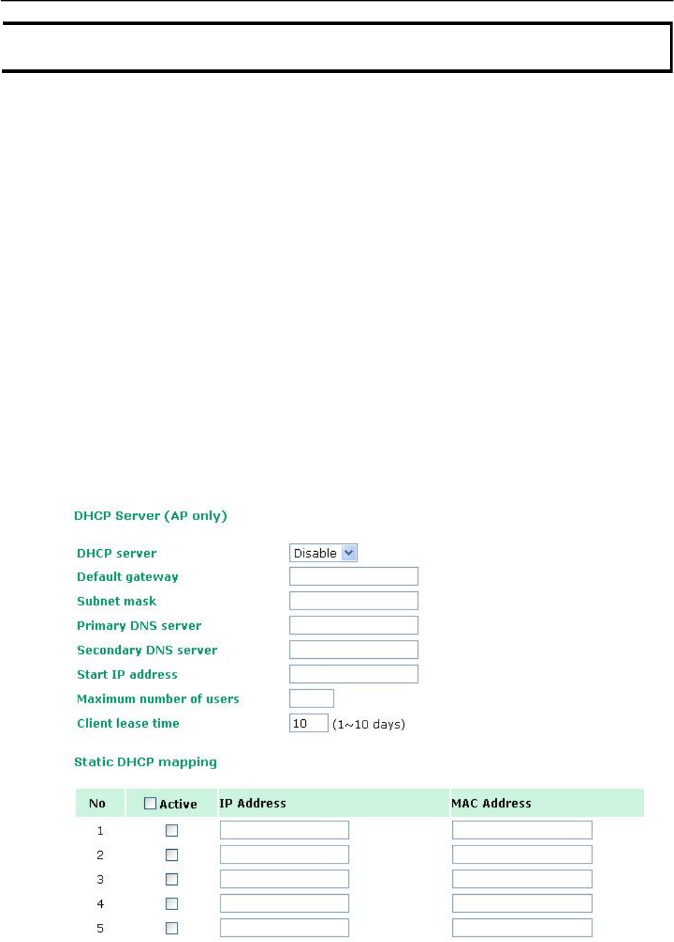
DHCP Server (for AP mode only)
DHCP (Dynamic Host Configuration Protocol) is a networking protocol that allows administrators to assign
temporary IP addresses to network computers by “leasing” an IP address to a user for a limited amount of
time, instead of assigning permanent IP addresses.
The AWK-1131A can act as a simplified DHCP server and easily assign IP addresses to your DHCP clients by
responding to the DHCP requests from the client ends. The IP-related parameters you set on this page will
also be sent to the client.
You can also assign a static IP address to a specific client by entering its MAC address. The AWK-1131A
provides a Static DHCP mapping list with up to 16 entities. Be reminded to check the Active check box
for each entity to activate the setting.
You can check the IP assignment status under Status DHCP Client List.
3-20
AirWorks AWK-1131A Web Console Configuration
DHCP server
Setting Description Factory Default
Enable Enables AWK-1131A as a DHCP server Disable
Disable Disable DHCP server function
Default gateway
Setting Description Factory Default
IP address of a default The IP address of the router that connects to an outside None
gateway network
Subnet mask
Setting Description Factory Default
subnet mask Identifies the type of sub-network (e.g., 255.255.0.0 for a None
Class B network, or 255.255.255.0 for a Class C network)
Primary/ Secondary DNS server
Setting Description Factory Default
IP address of Primary/ The IP address of the DNS Server used by your network. After None
Secondary DNS server
entering the DNS Server’s IP address, you can use URL as well.
The Secondary DNS server will be used if the Primary DNS
server fails to connect.
Start IP address
Setting Description Factory Default
IP address
Indicates the IP address which AWK-1131A can start assigning
None
Maximum number of users
Setting Description Factory Default
1 – 999 Specifies how many IP address can be assigned continuously None
Client lease time
Setting Description Factory Default
1 – 10 days The lease time for which an IP address is assigned. The IP 10 (days)
address may go expired after the lease time is reached.
Packet Filters
The AWK-1131A includes various filters for IP-based packets going through LAN and WLAN interfaces.
You can set these filters as a firewall to help enhance network security.
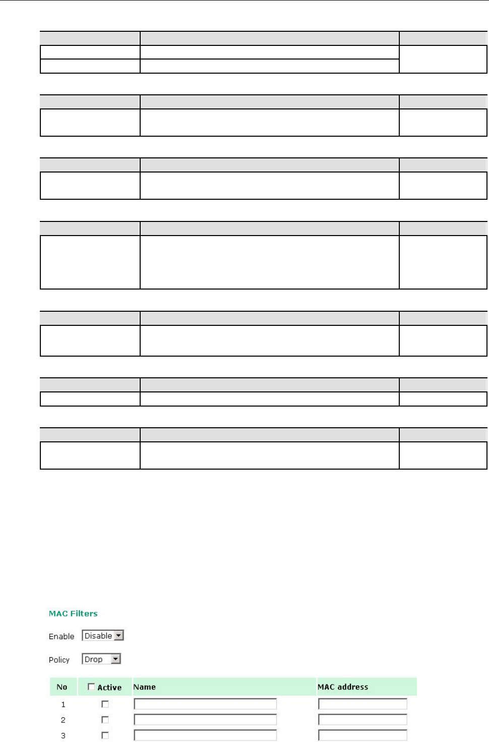
MAC Filter
The AWK-1131A’s MAC filter is a policy-based filter that can allow or filter out IP-based packets with
specified MAC addresses. The AWK-1131A provides 8 entities for setting MAC addresses in your filtering
policy. Remember to check the Active check box for each entity to activate the setting.
3-21
AirWorks AWK-1131A Web Console Configuration
Enable
Setting Description Factory Default
Enable Enables MAC filter Disable
Disable Disables MAC filter
Policy
Setting Description Factory Default
Accept Only the packets fitting the entities on list can be allowed. Drop
Drop Any packet fitting the entities on list will be denied.
ATTENTION
Be careful when you enable the filter function:
Drop + “no entity on list is activated” = all packets are allowed
Accept + “no entity on list is activated” = all packets are denied
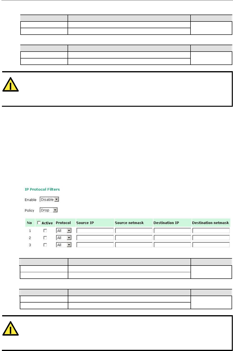
IP Protocol Filter
The AWK-1131A’s IP protocol filter is a policy-based filter that can allow or filter out IP-based packets
with specified IP protocol and source/destination IP addresses.
The AWK-1131A provides 8 entities for setting IP protocol and source/destination IP addresses in your
filtering policy. Four IP protocols are available: All, ICMP, TCP, and UDP. You must specify either the
Source IP or the Destination IP. By combining IP addresses and netmasks, you can specify a single IP
address or a range of IP addresses to accept or drop. For example, “IP address 192.168.1.1 and netmask
255.255.255.255” refers to the sole IP address 192.168.1.1. “IP address 192.168.1.1 and netmask
255.255.255.0” refers to the range of IP addresses from 192.168.1.1 to 192.168.255. Remember to check
the Active check box for each entity to activate the setting.
Enable
Setting Description Factory Default
Enable Enables IP protocol filter Disable
Disable Disables IP protocol filter
Policy
Setting Description Factory Default
Accept Only the packets fitting the entities on the list can be allowed Drop
Drop Any packet fitting the entities on the list will be denied
ATTENTION
Be careful when you enable the filter function:
Drop + “no entity on list is activated” = all packets are allowed.
Accept + “no entity on list is activated” = all packets are denied.
3-22
AirWorks AWK-1131A Web Console Configuration
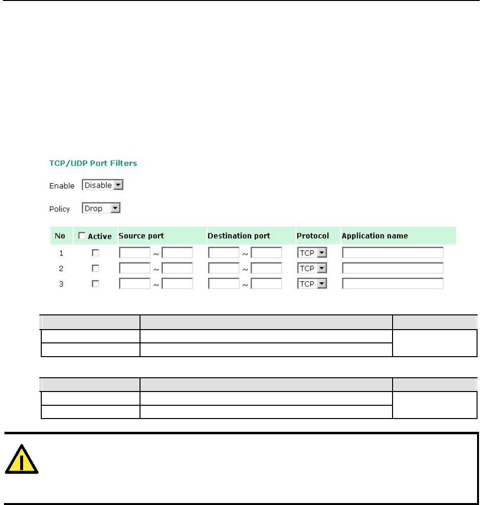
TCP/UDP Port Filter
The AWK-1131A’s TCP/UDP port filter is a policy-based filter that can allow or filter out TCP/UDP-based
packets with a specified source or destination port.
The AWK-1131A provides 8 entities for setting the range of source/destination ports of a specific protocol. In
addition to selecting TCP or UDP protocol, you can set either the source port, destination port, or both. The
end port can be left empty if only a single port is specified. Of course, the end port cannot be larger then
the start port.
The Application name is a text string that describes the corresponding entity with up to 31
characters. Remember to check the Active check box for each entity to activate the setting.
Enable
Setting Description Factory Default
Enable Enables TCP/UDP port filter Disable
Disable Disables TCP/UDP port filter
Policy
Setting Description Factory Default
Accept Only the packets fitting the entities on list can be allowed. Drop
Drop Any packet fitting the entities on list will be denied.
ATTENTION
Be careful when you enable the filter function:
Drop + “no entity on list is activated” = all packets are allowed
Accept + “no entity on list is activated” = all packets are denied
3-23
AirWorks AWK-1131A Web Console Configuration
SNMP Agent
The AWK-1131A supports SNMP V1/V2c/V3. SNMP V1 and SNMP V2c use a community string match for
authentication, which means that SNMP servers access all objects with read-only or read/write
permissions using the community string public/private (default value). SNMP V3, which requires you to
select an authentication level of MD5 or SHA, is the most secure protocol. You can also enable data
encryption to enhance data security.
The AWK-1131A’s MIB can be found in the software CD and supports reading the attributes via SNMP.
(Only get method is supported.)
SNMP security modes and security levels supported by the AWK-1131A are shown in the following table. Select the
security mode and level that will be used to communicate between the SNMP agent and manager.
Protocol Setting on Authenticati Data Method
Version UI web on Type Encryption
page
SNMP V1, V2c Community No Use a community string match for authentication
V1, V2c Read string
Community
V1, V2c Community No Use a community string match for authentication
Write/Read string
Community
SNMP V3 No-Auth No No Use account with admin or user to access objects
MD5 or SHA Authenticatio No Provides authentication based on HMAC-MD5, or
n based on
HMAC-SHA algorithms. 8-character passwords are the
MD5 or SHA minimum requirement for authentication.
MD5 or SHA Authenticatio Data Provides authentication based on HMAC-MD5 or
n based on encryption HMAC-SHA algorithms, and data encryption key.
MD5 or SHA key 8-character passwords and a data encryption key are
the minimum requirements for authentication and
encryption.
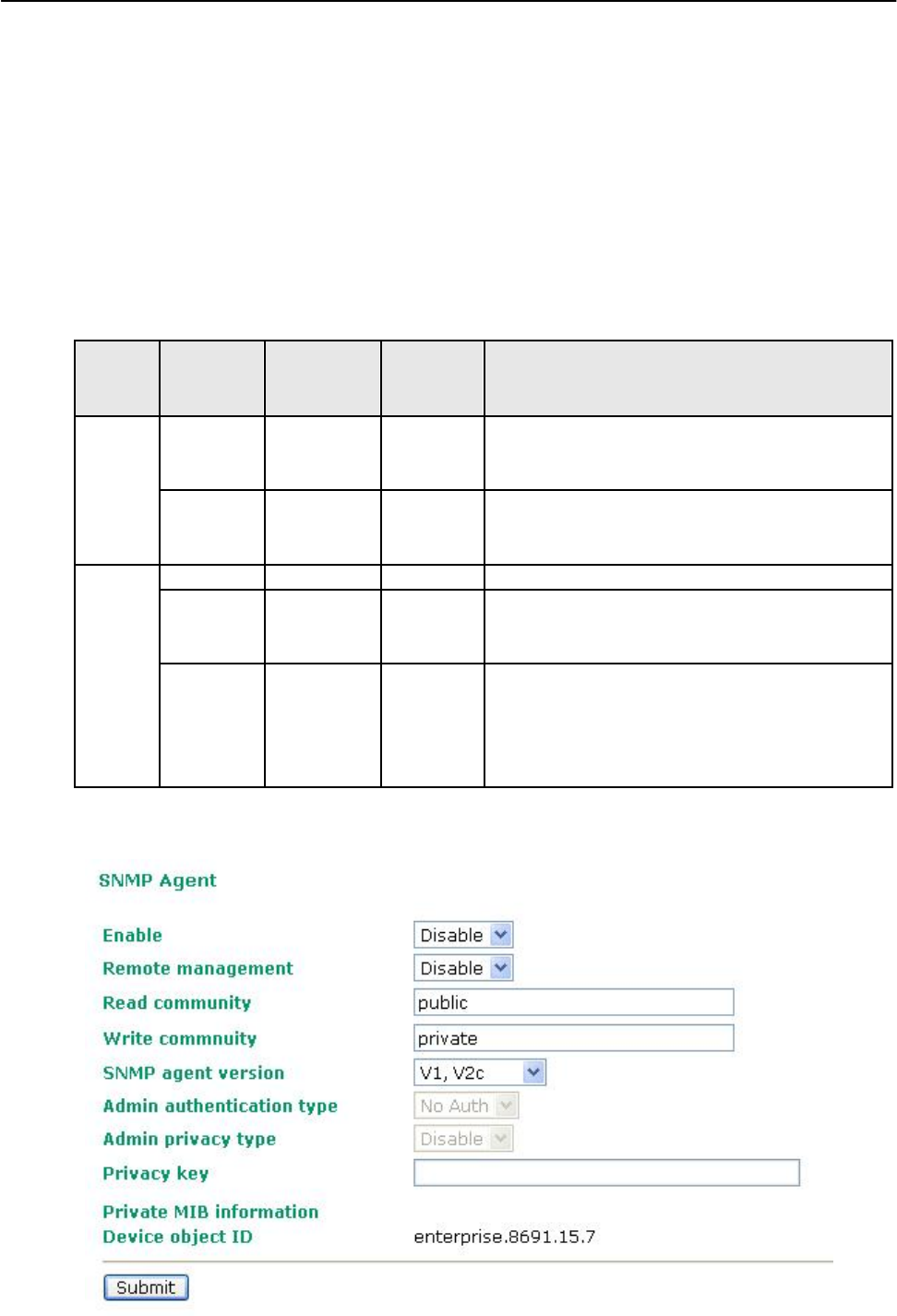
The following parameters can be configured on the SNMP Agent page. A more detailed explanation of
each parameter is given below the following figure.
3-24

AirWorks AWK-1131A Web Console Configuration
Enable
Setting Description Factory Default
Enable Enables SNMP Agent Disable
Disable Disables SNMP Agent
Remote Management
Setting Description Factory Default
Enable Allow remote management via SNMP agent Disable
Disable Disallow remote management via SNMP agent
Read community (for V1, V2c)
Setting Description Factory Default
V1, V2c Read Use a community string match with a maximum of 31 public
Community
characters for authentication. This means that the SNMP agent
can access all objects with read-only permissions using this
community string.
Write community (for V1, V2c)
Setting Description Factory Default
V1, V2c Read /Write Use a community string match with a maximum of 31 private
Community
characters for authentication. This means that the SNMP agent
can accesses all objects with read/write permissions using this
community string.
SNMP agent version
Setting Description Factory Default
V1, V2c, V3, or Select the SNMP protocol version used to manage the switch. V1, V2c
V1, V2c, or
V3 only
Admin auth type (for V1, V2c, V3, and V3 only)
Setting Description Factory Default
No Auth Use admin account to access objects. No authentication No Auth
MD5 Provide authentication based on the HMAC-MD5 algorithms.
8-character passwords are the minimum requirement for
authentication.
SHA Provides authentication based on
HMAC-SHA algorithms. 8-character passwords are the
minimum requirement for authentication.
Admin private key (for V1, V2c, V3, and V3 only)
Setting Description Factory Default
Disable No data encryption Disable
DES DES-based data encryption
AES AES-based data encryption
Private key
A data encryption key is the minimum requirement for data encryption (maximum of 63 characters)
Private MIB Information Device Object ID
Also know as OID. This is the AWK-1131A’s enterprise value. It is fixed.
3-25
AirWorks AWK-1131A Web Console Configuration
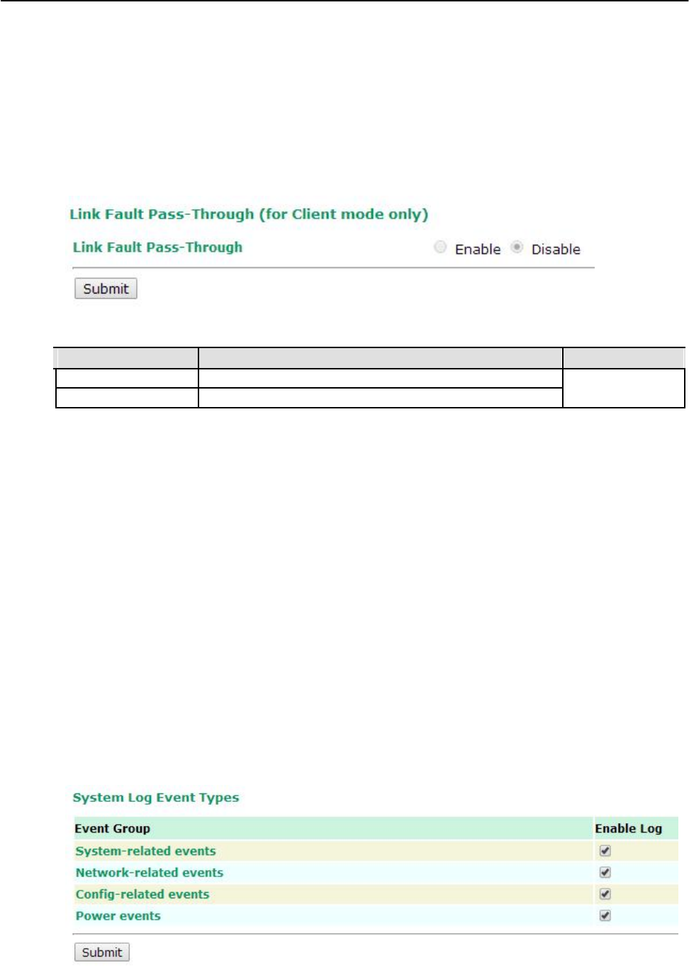
Link Fault Pass-Through (for Client mode only)
This function means if Ethernet port is link down, wireless connection will be forced to disconnect.
Once Ethernet link is recovered, AWK will try to connect to AP.
If wireless is disconnected, AWK restarts auto-negotiation on Ethernet port but always stays in the link
failure state. Once the wireless connection is recovered, AWK will try to recover the Ethernet link.
System log will indicate the link fault pass through events in addition to the original link up/down events.
Link Fault Pass-Through
Setting Description Factory Default
Enable Enables Link Fault Pass-Through Disable
Disable Disables Link Fault Pass-Through
Auto Warning Settings
Since industrial-grade devices are often located at the endpoints of a system, these devices will not always
know what is happening elsewhere on the network. This means that these devices, including wireless APs
or clients, must provide system maintainers with real-time alarm messages. Even when system
administrators are out of the control room for an extended period, they can still be informed of the status
of devices almost instantaneously when exceptions occur.
In addition to logging these events, the AWK-1131A supports different approaches to warn engineers
automatically, such as SNMP trap, e-mail, and relay output. It also supports two digital inputs to
integrate sensors into your system to automate alarms by email and relay output.
System Log
System Log Event Types
Detail information for grouped events is shown in the following table. You can check the box for Enable log to
enable the grouped events. All default values are enabled (checked). The log for system events can be seen in
Status System Log.
3-26
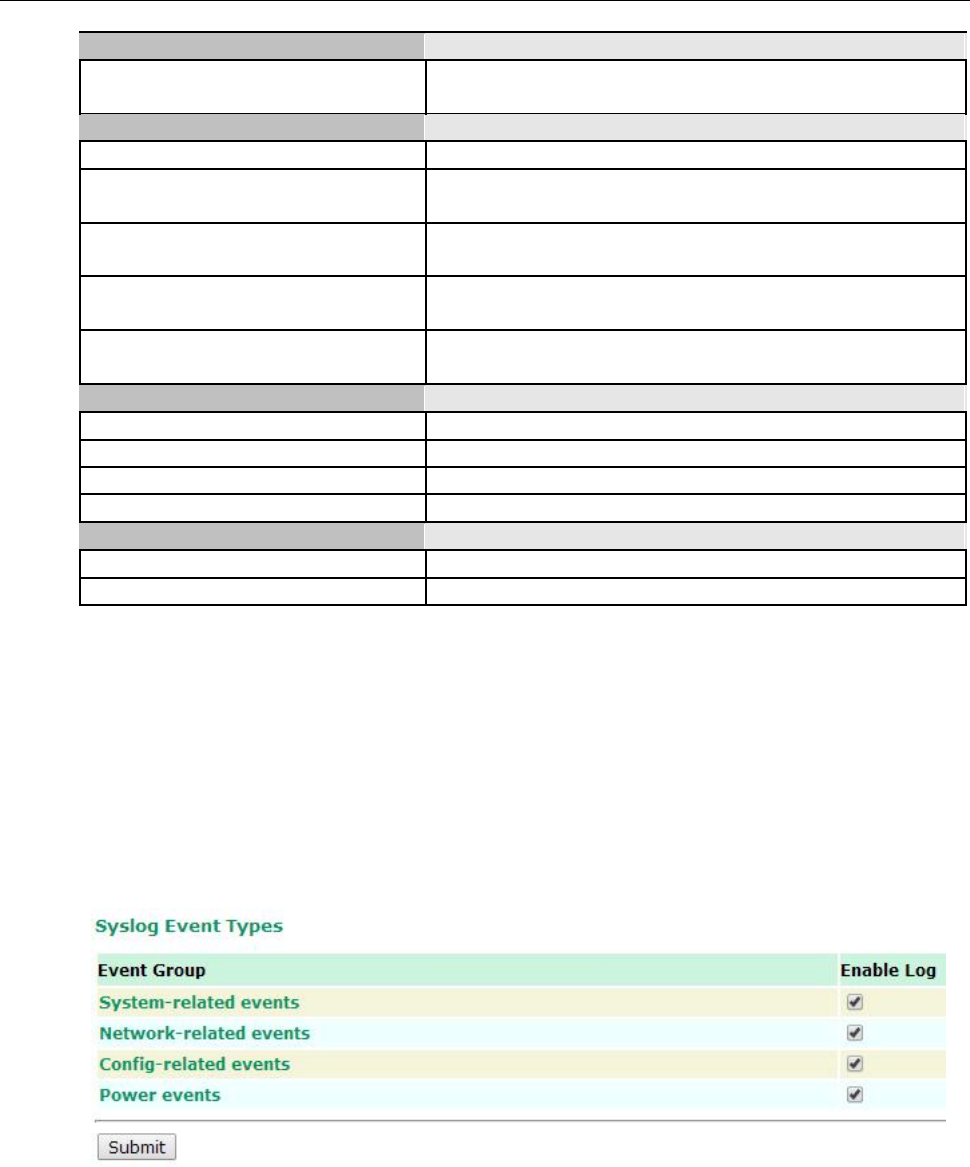
AirWorks AWK-1131A Web Console Configuration
System-related events Event is triggered when…
System restart (warm start) The AWK-1131A is rebooted, such as when its settings are
changed (IP address, subnet mask, etc.).
Network-related events Event is triggered when…
LAN link on The LAN port is connected to a device or network.
LAN link off The port is disconnected (e.g., the cable is pulled out, or the
opposing device shuts down).
Client joined/ left A wireless client is associated or disassociated.
(for AP mode)
WLAN connected to AP The AWK-1131A is associated with an AP.
(for Client mode)
WLAN disconnected The AWK-1131A is disassociated from an AP.
(for Client mode)
Config-related events Event is triggered when…
Configuration Changed A configuration item has been changed.
Configuration file import via Web Console The configuration file is imported to the AWK-1131A.
Console authentication failure An incorrect password is entered.
Firmware upgraded The AWK-1131A’s firmware is updated.
Power events Event is triggered when…
Power 1/2 transition (On -> Off) The AWK-1131A is powered down in PWR1/2.
Power 1/2 transition (Off -> On) The AWK-1131A is powered via PWR1/2.
Syslog
This function provides the event logs for the Syslog server. The function supports up to three configurable
Syslog servers and Syslog server UDP port numbers. When an event occurs, the event will be sent as a
Syslog UDP packet to the specified Syslog servers.
Syslog Event Types
Detail information for the grouped events is shown in the following table. You can check the box for Enable
log to enable the grouped events. All default values are enabled (checked). Details for each event group
can be found on the “System log Event Types” table on page 3-31.
3-27
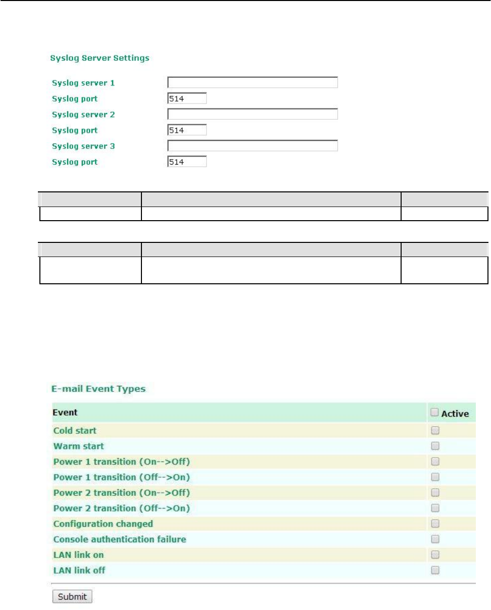
AirWorks AWK-1131A Web Console Configuration
Syslog Server Settings
You can configure the parameters for your Syslog servers in this page.
Syslog server 1/ 2/ 3
Setting Description Factory Default
IP address Enter the IP address of the 1st/ 2nd/ 3rd Syslog Server None
Syslog port
Setting Description Factory Default
Port destination Enter the UDP port of the corresponding Syslog server 514
(1 to 65535)
E-mail
E-mail Event Types
Check the box for Active to enable the event items. All default values are deactivated (unchecked). Details
for each event item can be found on the “System log Event Types” table on page 3-31.
3-28
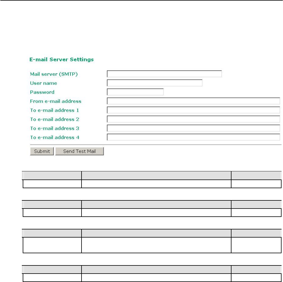
AirWorks AWK-1131A Web Console Configuration
E-mail Server Settings
You can set up to 4 e-mail addresses to receive alarm emails from the AWK-1131A. The following
parameters can be configured on the E-mail Server Settings page. In addition, a Send Test Mail button
can be used to test whether the Mail server and e-mail addresses work well. More detailed explanations
about these parameters are given after the following figure.
Mail server (SMTP)
Setting Description Factory Default
IP address The IP Address of your email server. None
User name & Password
Setting Description Factory Default
User name and password used in the SMTP server None
From e-mail address
Setting Description Factory Default
Max. 63 characters
Enter the administrator’s e-mail address which will be shown in
None
the “From” field of a warning e-mail.
To E-mail address 1/ 2/ 3/ 4
Setting Description Factory Default
Max. 63 characters Enter the receivers’ e-mail addresses. None
3-29
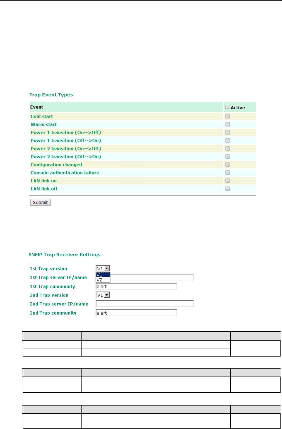
AirWorks AWK-1131A Web Console Configuration
Trap
Traps can be used to signal abnormal conditions (notifications) to a management station. This trap-
driven notification can make your network more efficient.
Because a management station usually takes care of a large number of devices that have a large number
of objects, it will be overloading for the management station to poll or send requests to query every object
on every device. It would be better if the managed device agent could notify the management station by
sending a message known as a trap for the event.
Trap Event Types
SNMP Trap Receiver Settings
SNMP traps are defined in SMIv1 MIBs (SNMPv1) and SMIv2 MIBs (SNMPv2c). The two styles are basically
equivalent, and it is possible to convert between the two. You can set the parameters for SNMP trap
receivers through the web page.
1st / 2nd Trap version
Setting Description Factory Default
V1 SNMP trap defined in SNMPv1 V1
V2 SNMP trap defined in SNMPv2
1st / 2nd Trap server IP/name
Setting Description Factory Default
IP address or host Enter the IP address or name of the trap server used by your None
name network.
1st / 2nd Trap community
Setting Description Factory Default
Max. of 31 characters Use a community string match with a maximum of 31 alert
characters for authentication.
3-30
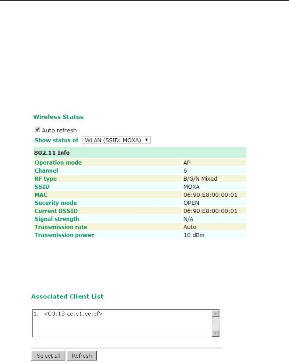
AirWorks AWK-1131A Web Console Configuration
Status
Wireless Status
The status for 802.11 info parameters, such as Operation mode and Channel, are shown on the
Wireless Status page. The status will refresh every 5 seconds if the Auto refresh box is checked.
Certain values for 802.11 info may not show up due to different operation modes. As a result, Current
BSSID and Signal strength are not available in AP mode.
It is helpful to use the continuously updated information on this page, such as Signal strength, to monitor
the signal strength of the AWK-1131A in Client mode.
Associated Client List (for AP mode only)
Associated Client List shows all the clients that are currently associated to a particular AWK-1131A. You can click
Select all to select all the content in the list for further editing. You can click Refresh to refresh the list.
3-31
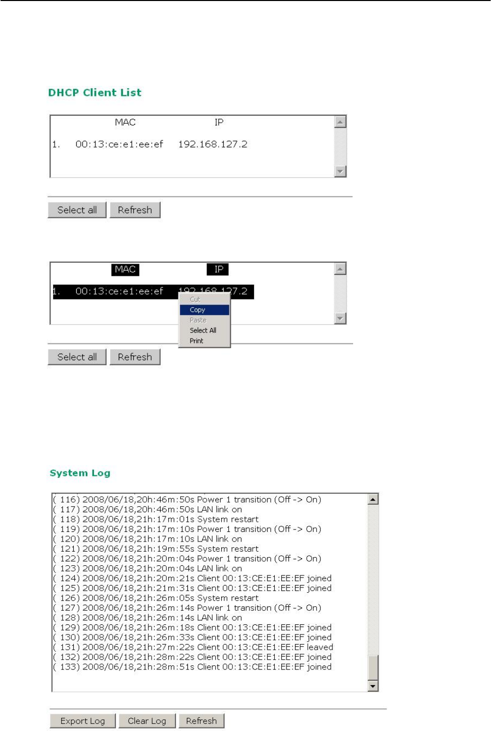
AirWorks AWK-1131A Web Console Configuration
DHCP Client List (for AP mode only)
The DHCP Client List shows all the clients that require and have successfully received IP assignments. You
can click the Refresh button to refresh the list.
You can press Select all button to select all content in the list for further editing.
System Log
Triggered events are recorded in System Log. You can export the log contents to an available viewer by
clicking Export Log. You can use the Clear Log button to clear the log contents and the Refresh button to
refresh the log.
3-32
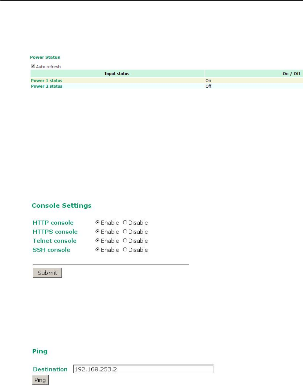
AirWorks AWK-1131A Web Console Configuration
Power Status
The status of power inputs and digital inputs is shown on this web page. The status will refresh every 5
seconds if the Auto refresh box is checked.
Maintenance
Maintenance functions provide the administrator with tools to manage the AWK-1131A and
wired/wireless networks.
Console Settings
You can enable or disable access permission for the following consoles: HTTP, HTTPS, Telnet and SSH
connections. For more security, we recommend you only allow access to the two secured consoles, HTTPS
and SSH.
Ping
Ping helps to diagnose the integrity of wired or wireless networks. By inputting a node’s IP address in the
Destination field, you can use the ping command to make sure it exists and whether or not the access
path is available.
3-33
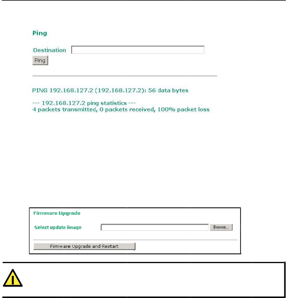
AirWorks
A
If
n
o
Firmw
a
T
h
la
t
B
e
s
p
A
f
W
A
T
Pl
e
br
A
WK-1131
A
the node an
d
o
loss. Other
w
a
re Up
g
h
e AWK-1131
A
t
est firmware
e
fore running
p
ecify the fir
m
f
ter the progr
e
hen upgradin
g
T
TENTIO
N
e
ase make su
eakup may d
a
A
d
access path
w
ise, some, or
g
rade
A
can be en
h
is available a
a firmware
u
m
ware image
f
e
ss bar reach
e
g
your firmw
a
N
re the power
a
mage your
A
are available
even all, pac
h
anced with
m
t Moxa’s dow
n
u
pgrade, ma
k
f
ile and click
F
e
s 100%, the
a
re, the AWK-
source is sta
b
A
WK-1131A.
, you will se
e
kets may get
m
ore value-a
d
n
load center.
k
e sure the
A
F
irmware U
p
AWK-1131A
w
1131A’s othe
r
b
le when you
3-34
e
that all pac
k
lost, as show
d
ded function
s
A
WK-1131A i
s
p
grade and
R
w
ill reboot its
e
r
functions ar
e
upgrade you
r
Web C
k
ets were suc
c
n in the follo
w
s
by installin
g
s
of
f
-line. Cli
c
R
estart to st
a
e
lf.
e
forbidden.
r
firmware. A
n
onsole Con
f
c
essfully tran
w
ing figure.
g
firmware u
p
c
k the Brow
s
a
rt the firmw
a
n
unexpected
f
iguration
smitted with
p
grades. The
s
e button to
a
re upgrade.
power
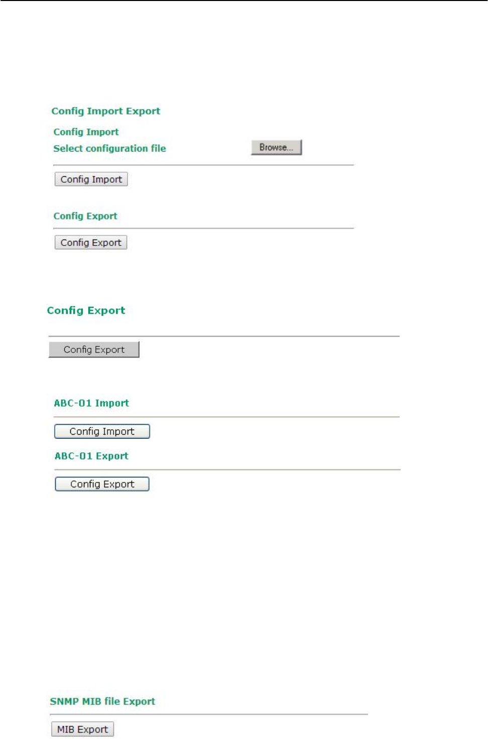
AirWorks AWK-1131A Web Console Configuration
Config Import Export
First way you can back up or restore the AWK-1131A’s configuration and MIB with Config Import Export.
In the Config Import section, click Browse to specify the configuration file and click Config Import
button to begin importing the configuration.
In the Config Export section, click the Config Export button and save the configuration file onto your local
storage media. The configuration file is a text file and you can view and edit it with a general text-editing tool.
You can also back up or restore the ABC-01 configuration with Config Import Export.
To download the configuration to the AWK:
1. Turn off the AWK.
2. Plug in the ABC-01 to the AWK’s RS-232 console.
3. Turn on AWK.
4. AWK will detect ABC-01 during bootup, and download the configuration from the ABC-01 to the AWK
automatically. Once the configuration downloads and if configuration format is correct, the AWK will
emit three short beeps, then continue the boot up.
5. Once the AWK has booted up successfully, it will emit the normal two beeps, and the ready LED will
turn to solid green.
For MIB file you can click SNMP MIB file Export to save the file onto your local storage media. The
configuration file is a .my file and you can import it with a general SNMP tool to remote control or set
AWK-1131A.
3-35
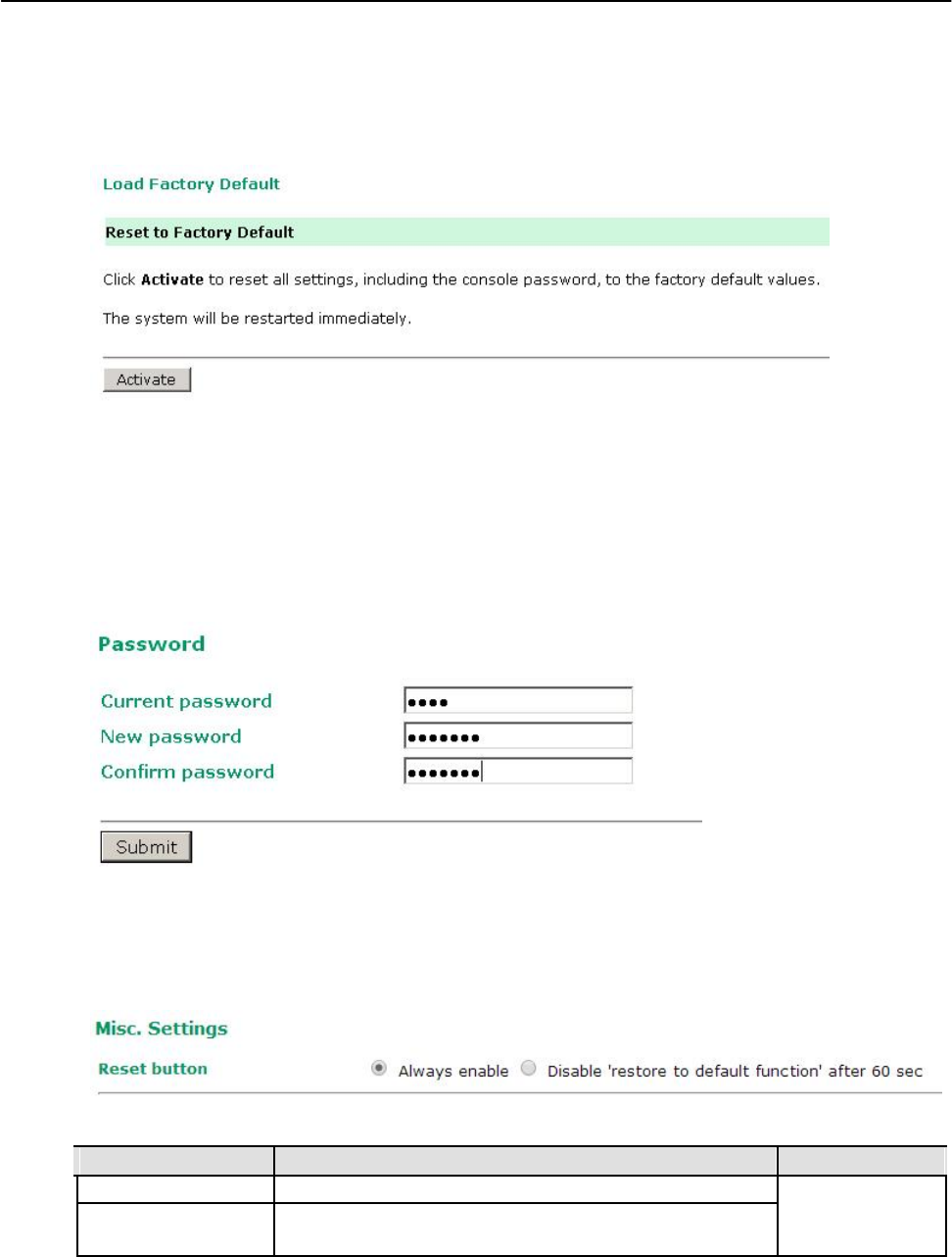
AirWorks AWK-1131A Web Console Configuration
Load Factory Default
Use this function to reset the AWK-1131A and roll all settings back to the factory default values. You can
also reset the hardware by pressing the reset button on the top panel of the AWK-1131A.
Password
You can change the administration password for each of the AWK-1131A’s console managers by using the
Password function. Before you set up a new password, you must input the current password and reenter
the new password for confirmation. For your security, do not use the default password root, and remember
to change the administration password regularly.
Misc. Settings
Additional settings to help you manage your AWK-1131A, are available on this page.
Reset button
Setting Description Factory Default
Always enable The AWK-1131A’s Reset button works normally. Always enable
Disable after 60 sec The AWK-1131A’s reset to default function will be inactive 60
seconds after the AWK-1131A finishes booting up.
3-36
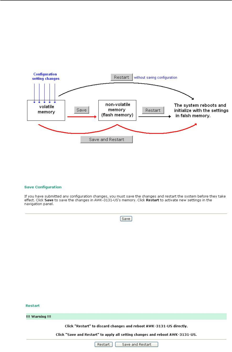
AirWorks AWK-1131A Web Console Configuration
Save Configuration
The following figure shows how the AWK-1131A stores the setting changes into volatile and non-volatile
memory. All data stored in volatile memory will disappear when the AWK-1131A is shutdown or rebooted
unless they are y. Because the AWK-1131A starts up and initializes with the settings stored in flash
memory, all new changes must be saved to flash memory before restarting the AWK-1131A.
This also means the new changes will not work unless you run either the Save Configuration function or
the Restart function.
After you click on Save Configuration in the left menu box, the following screen will appear. Click Save if
you wish to update the configuration settings in the flash memory at this time. Alternatively, you may
choose to run other functions and put off saving the configuration until later. However, the new setting
changes will remain in the non-volatile memory until you save the configurations.
Restart
If you submitted configuration changes, you will find a blinking string in the upper right corner of the
screen. After making all your changes, click the Restart function in the left menu box. One of two different
screens will appear.
If you made changes recently but did not save, you will be given two options. Clicking the Restart button
here will reboot the AWK-1131A directly, and all setting changes will be ignored. Clicking the Save and
Restart button will apply all setting changes and then reboot the AWK-1131A.
3-37
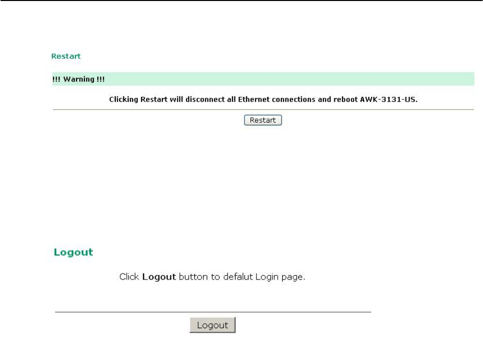
AirWorks AWK-1131A Web Console Configuration
If you run the Restart function without changing any configurations or saving all your changes, you will
see just one Restart button on your screen.
You will not be able to run any of the AWK-1131A’s functions while the system is rebooting.
Logout
Logout helps users disconnect the current HTTP or HTTPS session and go to the Login page. For
security reasons, we recommend you logout before quitting the console manager.
3-38

4
4. Software Installation and Configuration
The following topics are covered in this chapter:
Overview
AWK Search Utility
Installing AWK Search Utility
Configuring AWK Search Utility
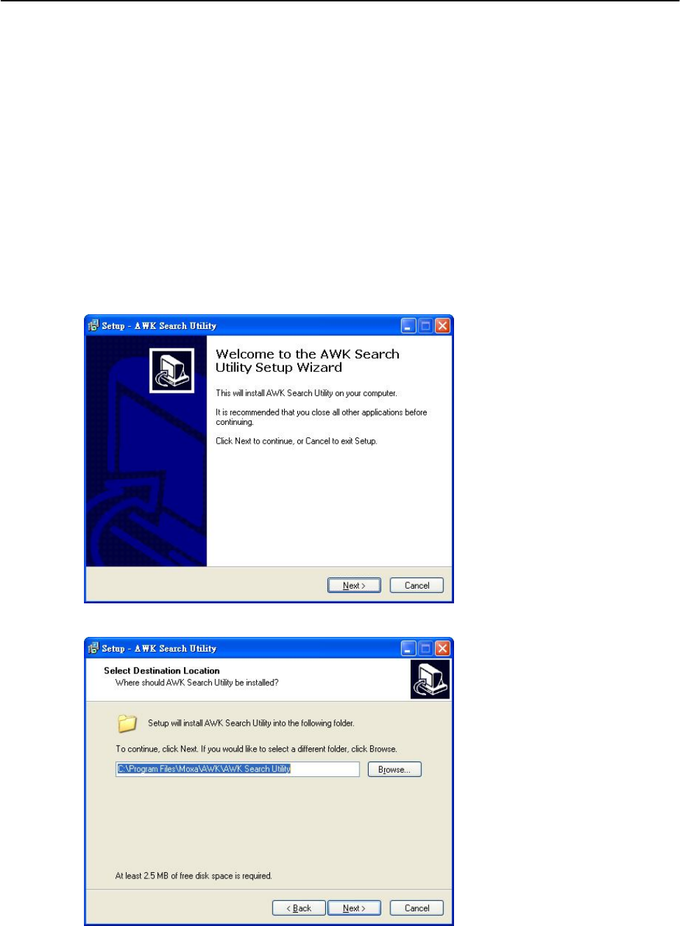
AirWorks AWK-1131A Software Installation and Configuration
Overview
The Documentation & Software CD included with your AWK-1131A is designed to make the installation and
configuration procedure easy and straightforward. This auto-run CD includes AWK Search Utility (to broadcast
search for all AWK’s accessible over the network), the AWK-1131A User’s Manual, and Quick Installation Guide.
AWK Search Utility
Installing AWK Search Utility
Click the INSTALL UTILITY button in the AWK Installation CD auto-run window to install AWK Search
Utility. Once the program starts running, click Yes to proceed.
1. Click Next when the Welcome screen opens to proceed with the installation.
2. Click Next to install program files to the default directory, or click Browse to select an alternate location.
3. Click Next to create the program’s shortcut files to the default directory, or click Browse to select
an alternate location.
4-2
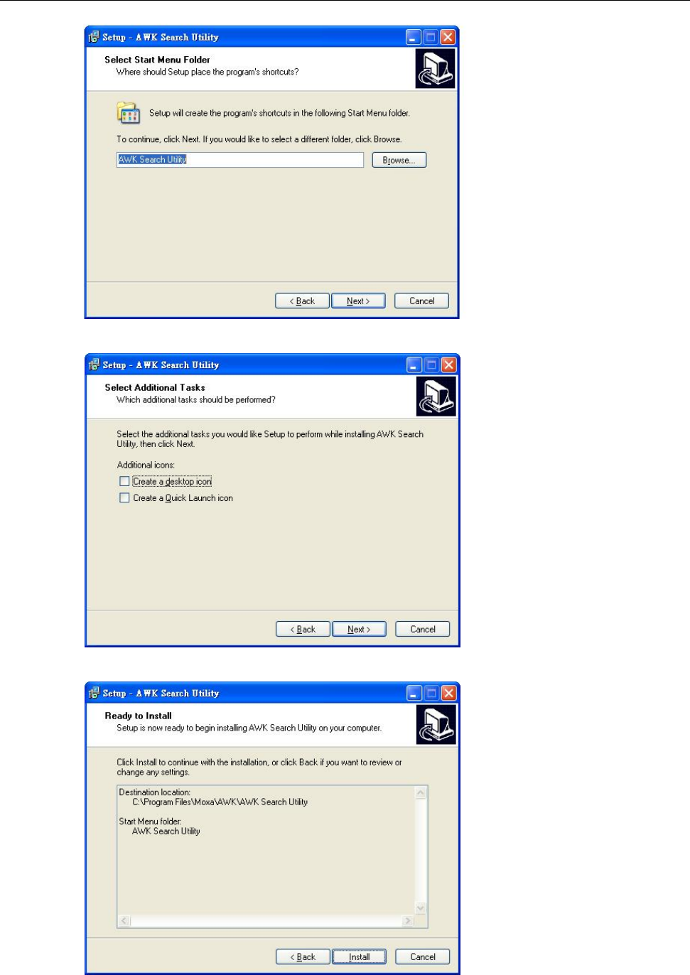
AirWorks AWK-1131A Software Installation and Configuration
4. Click Next to select additional tasks.
5. Click Next to proceed with the installation. The installer then displays a summary of the installation options.
6. Click Install to begin the installation. The setup window will report the progress of the installation.
To change the installation settings, click Back and navigate to the previous screen.
4-3
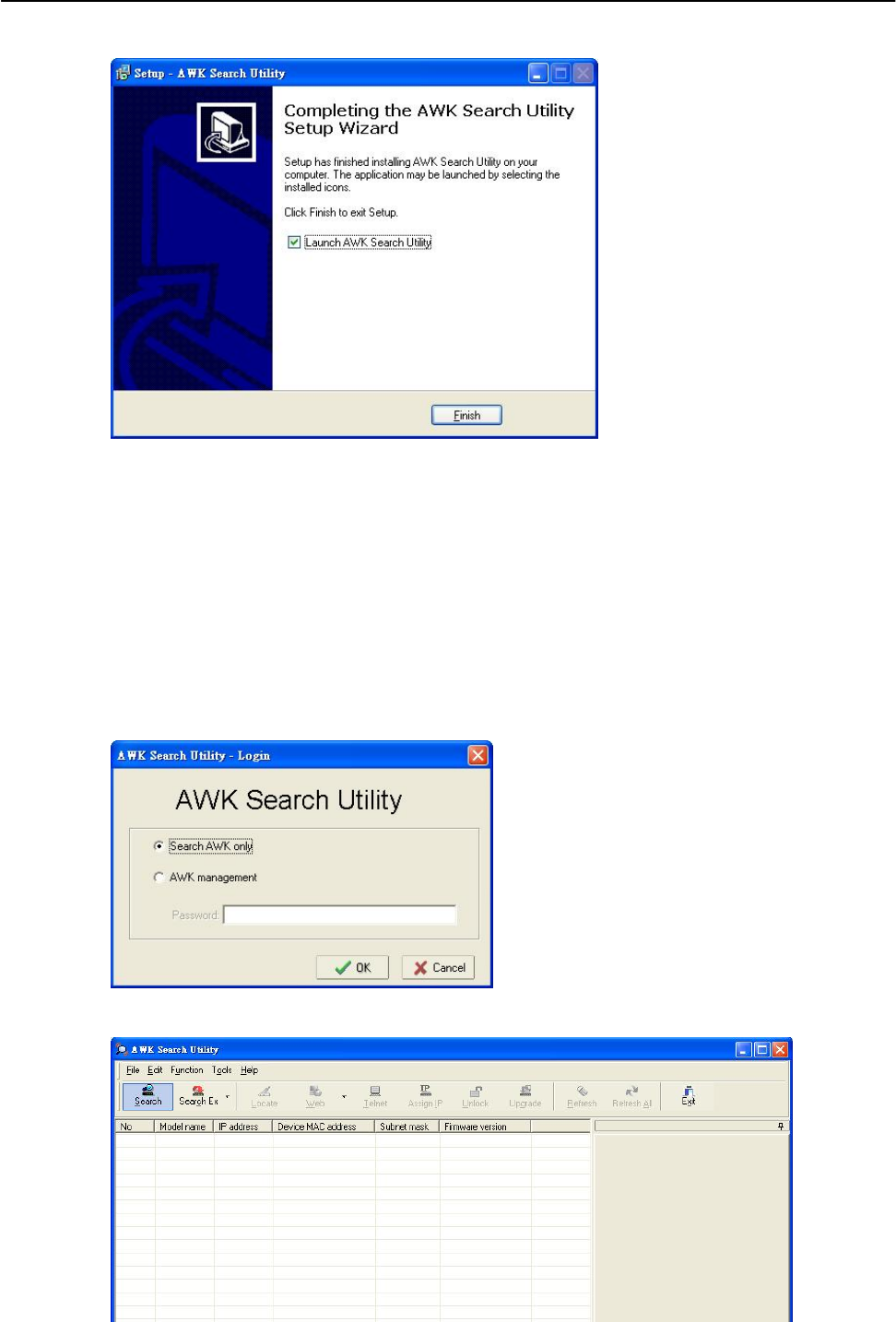
AirWorks AWK-1131A Software Installation and Configuration
7. Click Finish to complete the installation of AWK Search Utility.
Configuring AWK Search Utility
The Broadcast Search function is used to locate all AWK-1131A APs that are connected to the same LAN as
your computer. After locating an AWK-1131A, you will be able to change its IP address. Since the Broadcast
Search function searches by TCP packet and not IP address, it doesn’t matter if the AWK-1131A is
configured as an AP or Client. In either case, APs and Clients connected to the LAN will be located,
regardless of whether or not they are part of the same subnet as the host.
1. Start the AWK Search Utility program. When the Login page appears, select the “Search AWK only”
option to search for AWKs and to view each AWK’s configuration. Select the “AWK management” option
to assign IPs, upgrade firmware, and locate devices.
2. Open the AWK Search Utility and then click the Search icon.
4-4
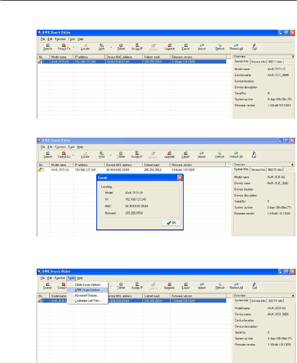
AirWorks AWK-1131A Software Installation and Configuration
3. The “Searching” window indicates the progress of the search. When the search is complete, all AWKs
that were located will be displayed in the AWK Search Utility window.
4. Click Locate to cause the selected device to beep.
5. Make sure your AWK is unlocked before using the search utility’s icons setting. The AWK will unlock
automatically if the password is set to the default. Otherwise you must enter the new password manually.
6. Go to Tools AWK login Options to manage and unlock additional AWKs.
7. Use the scroll down list to select the MAC addresses of those AWKs you would like to manage, and then
click Add. Key in the password for the AWK device and then click OK to save. If you return to the search
page and search for the AWK again, you will find that the AWK will unlock automatically.
4-5
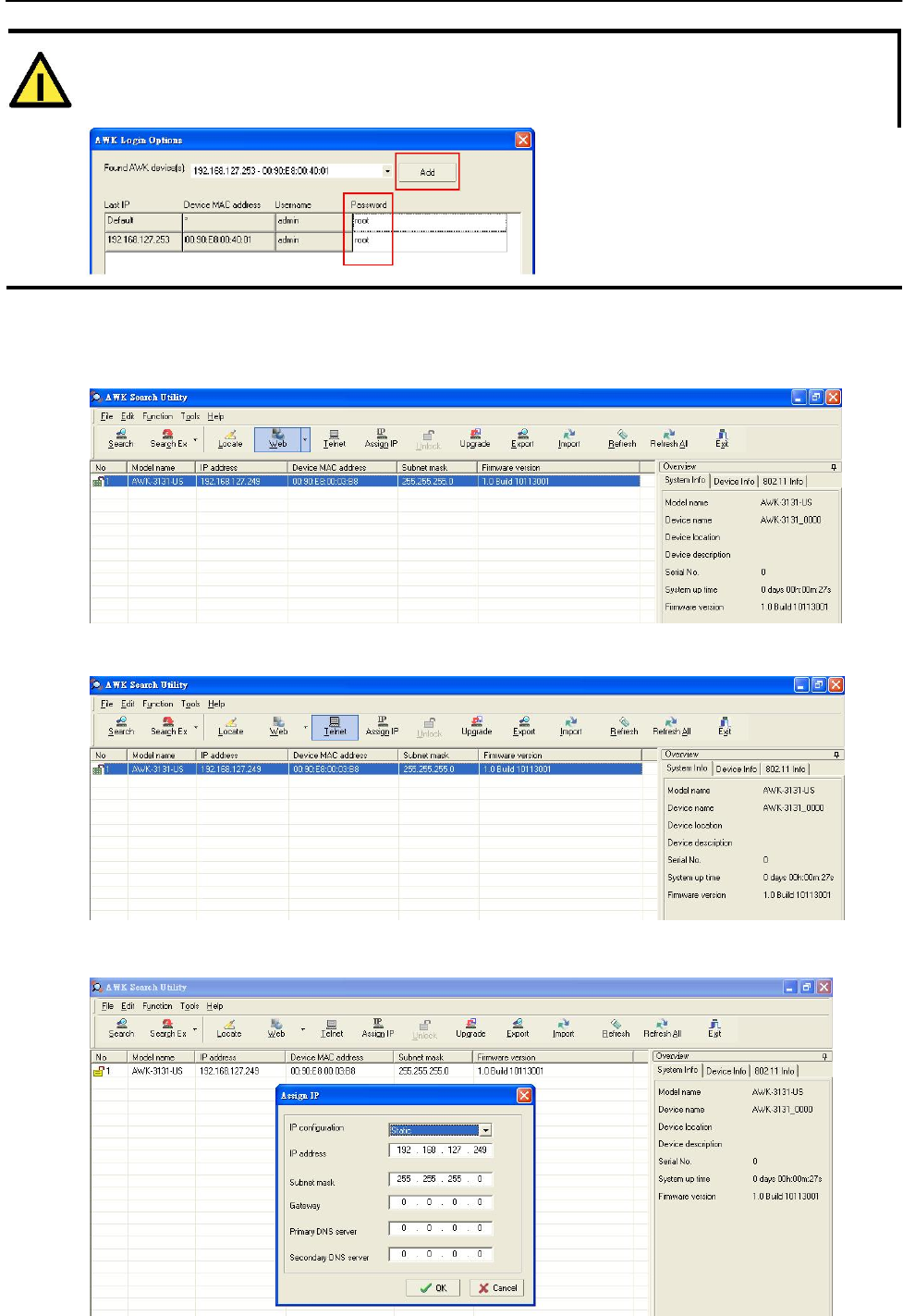
AirWorks AWK-1131A Software Installation and Configuration
ATTENTION
For security purposes, we suggest you can change the AWK search utility login password instead of using
the default.
To modify the configuration of the highlighted AWK, click on the Web icon to open the web console. This will
take you to the web console, where you can make all configuration changes. Refer to Chapter 3, “Using the
Web Console,” for information on how to use the web console.
Click on Telnet if you would like to use telnet to configure your AWKs.
Click Assign IP to change the IP setting.
4-6
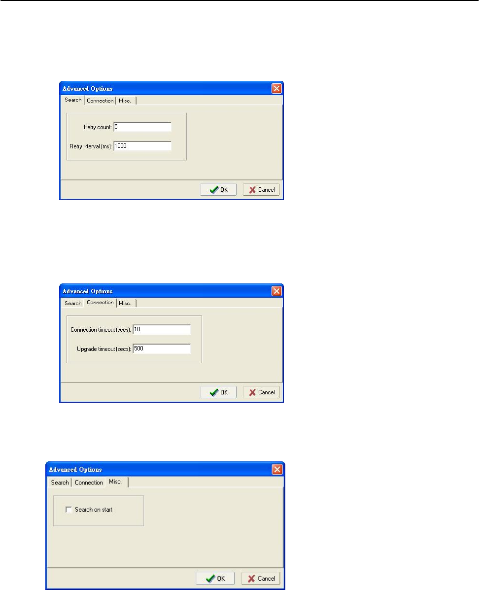
AirWorks AWK-1131A Software Installation and Configuration
The three advanced options—Search, Connection, and Miscellaneous—are explained below:
Search
• Retry count (default=5): Indicates how many times the search will be retried automatically.
• Retry interval (ms): The time lapsed between retries.
Connection
• Connection timeout (secs): Use this option to set the waiting time for the Default Login,
Locate, Assign IP, Upload Firmware, and Unlock to complete.
• Upgrade timeout (secs): Use this option to set the waiting time for the connection to disconnect while the
firmware is upgrading. Use this option to set the waiting time for the Firmware to write to flash.
Misc.
Search on start: Checkmark this box if you would like the search function to start searching for devices
after you log in to the AWK search Utility.
4-7

5
5. Other Console Considerations
This chapter explains how to access the AWK-1131A for the first time. In addition to HTTP access, there are
four ways to access AWK-1131A: serial console, Telnet console, SSH console, and HTTPS console. The
serial console connection method, which requires using a short serial cable to connect the AWK-1131A to a
PC’s COM port, can be used if you do not know the AWK-1131A’s IP address. The other consoles can be
used to access the AWK-1131A over an Ethernet LAN, or over the Internet.
The following topics are covered in this chapter:
RS-232 Console Configuration (115200, None, 8, 1, VT100)
Configuration by Telnet and SSH Consoles
Configuration by Web Browser with HTTPS/SSL
Disabling Telnet and Browser Access
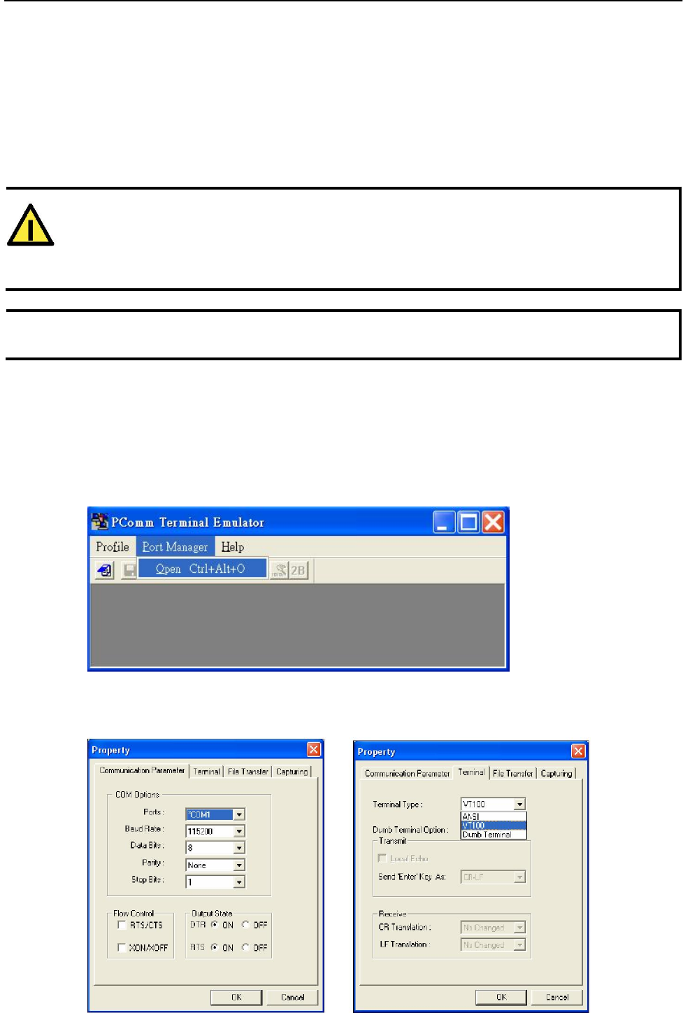
AirWorks AWK-1131A Other Console Considerations
RS-232 Console Configuration (115200, None, 8,
1, VT100)
The serial console connection method, which requires using a short serial cable to connect the AWK-1131A
to a PC’s COM port, can be used if you do not know the AWK-1131A’s IP address. It is also convenient to
use serial console configurations when you cannot access the AWK-1131A over Ethernet LAN, such as in the
case of LAN cable disconnections or broadcast storming over the LAN.
ATTENTION
Do not use the RS-232 console manager when the AWK-1131A is powered at reversed voltage (ex. -
48VDC), even though reverse voltage protection is supported.
If you need to connect the RS-232 console at reversed voltage, Moxa’s TCC-82 isolator is your best solution.
NOTE We recommend using Moxa PComm (Lite) Terminal Emulator, which can be downloaded free of
charge from Moxa’s website.
Before running PComm Terminal Emulator, use an RJ45 to DB9-F (or RJ45 to DB25-F) cable to connect the
AWK-1131A’s RS-232 console port to your PC’s COM port (generally COM1 or COM2, depending on how
your system is set up). After installing PComm Terminal Emulator, take the following steps to access the
RS-232 console utility.
1. From the Windows desktop, open the Start menu and start PComm Terminal Emulator in the PComm
(Lite) group.
2. Select Open under Port Manager to open a new connection.
3. The Communication Parameter page of the Property window opens. Select the appropriate COM port
for Console Connection, 115200 for Baud Rate, 8 for Data Bits, None for Parity, and 1 for Stop Bits.
Click on the Terminal tab, and select VT100 (or ANSI) for Terminal Type. Click on OK to continue.
5-2
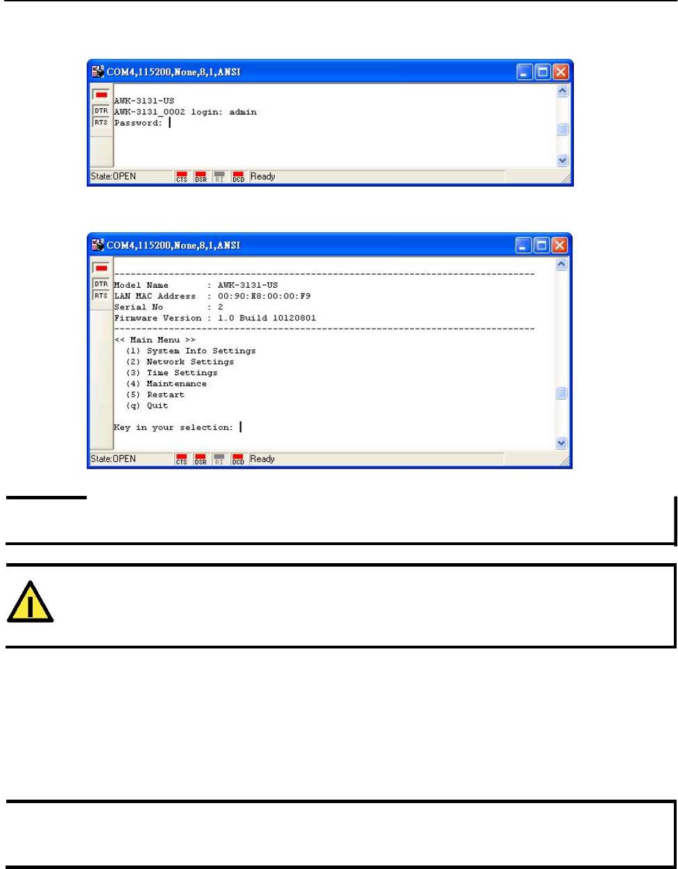
AirWorks AWK-1131A Other Console Considerations
4. The Console login screen will appear. Log into the RS-232 console with the login name (default:
admin) and password (default: root, if no new password is set).
5. The AWK-1131A’s device information and Main Menu will be displayed. Please follow the description
on screen and select the administration option you wish to perform.
NOTE To modify the appearance of the PComm Terminal Emulator window, select Edit Font and then choose the
desired formatting options.
ATTENTION
If you unplug the RS-232 cable or trigger DTR, a disconnection event will be evoked to enforce logout
for network security. You will need to log in again to resume operation.
Configuration by Telnet and SSH Consoles
You may use Telnet or SSH client to access the AWK-1131A and manage the console over a network. To
access the AWK-1131A’s functions over the network from a PC host that is connected to the same LAN as
the AWK-1131A, you need to make sure that the PC host and the AWK-1131A are on the same logical
subnet. To do this, check your PC host’s IP address and subnet mask.
NOTE The AWK-1131A’s default IP address is 192.168.127.253 and the default subnet mask is 255.255.255.0
(for a Class C network). If you do not set these values properly, please check the network settings of your
PC host and then change the IP address to 192.168.127.xxx and subnet mask to 255.255.255.0.
5-3
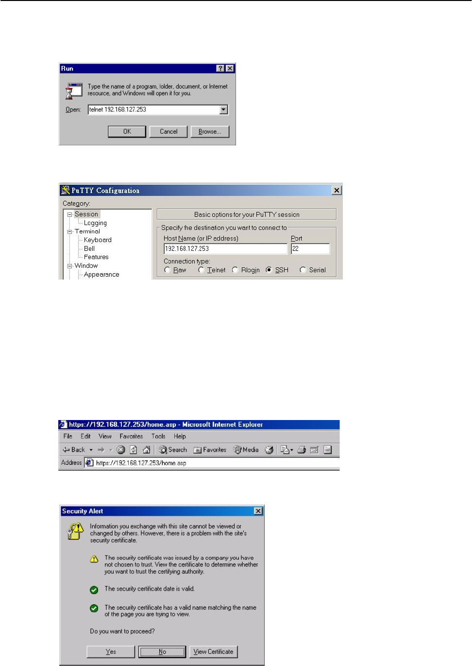
AirWorks AWK-1131A Other Console Considerations
Follow the steps below to access the console utility via Telnet or SSH client.
1. From Windows Desktop, run Start Run, and then use Telnet to access the AWK-1131A’s IP address from
the Windows Run window (you may also issue the telnet command from the MS-DOS prompt).
2. When using SSH client (ex. PuTTY), please run the client program (ex. putty.exe) and then input
the AWK-1131A’s IP address, specifying 22 for the SSH connection port.
3. The Console login screen will appear. Please refer to the previous paragraph “RS-232 Console
Configuration” and for login and administration.
Configuration by Web Browser with HTTPS/SSL
To secure your HTTP access, the AWK-1131A supports HTTPS/SSL encryption for all HTTP traffic. Perform
the following steps to access the AWK-1131A’s web browser interface via HTTPS/SSL.
1. Open your web browser and type https://<AWK-1131A’s IP address> in the address field. Press Enter
to establish the connection.
2. Warning messages will pop out to warn users that the security certificate was issued by a company
they have not chosen to trust.
5-4
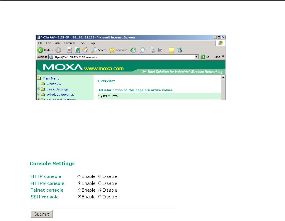
AirWorks AWK-1131A Other Console Considerations
3. Select Yes to accept the certificate issued by Moxa IW and then enter the AWK-1131A’s web browser interface
secured via HTTPS/SSL. (You can see the protocol in URL is https.) Then you can use the menu tree on the
left side of the window to open the function pages to access each of AWK-1131A’s functions.
Disabling Telnet and Browser Access
If you are connecting the AWK-1131A to a public network but do not intend to use its management
functions over the network, then we suggest disabling both Telnet Console and Web Configuration. Please
run Maintenance Console Settings to disable them, as shown in the following figure.
5-5

A
A. References
This chapter provides more detailed information about wireless-related technologies. The information in
this chapter can help you administer your AWK-1131As and plan your industrial wireless network better.
The following topics are covered in this appendix:
Beacon
DTIM
Fragment
RTS Threshold

AirWorks AWK-1131A References
Beacon
A beacon is a packet broadcast by the AP to keep the network synchronized. A beacon includes the wireless LAN
service area, the AP address, the Broadcast destination address, a time stamp, Delivery Traffic Indicator Maps
(DTIM), and the Traffic Indicator Message (TIM). Beacon Interval indicates the frequency interval of AP.
DTIM
Delivery Traffic Indication Map (DTIM) is contained in beacon frames. It is used to indicate that broadcast
and multicast frames buffered by the AP will be delivered shortly. Lower settings result in more efficient
networking, while preventing your PC from dropping into power-saving sleep mode. Higher settings allow
your PC to enter sleep mode, thus saving power.
Fragment
A lower setting means smaller packets, which will create more packets for each transmission. If you have
decreased this value and experience high packet error rates, you can increase it again, but it will likely
decrease overall network performance. Only minor modifications of this value are recommended.
RTS Threshold
RTS Threshold (256-2346) – This setting determines how large a packet can be before the Access Point
coordinates transmission and reception to ensure efficient communication. This value should remain at
its default setting of 2,346. When you encounter inconsistent data flow, only minor modifications are
recommended.
A-2

B
B. Supporting Information
This chapter presents additional information about this product. You can also learn how to contact Moxa
for technical support.
The following topics are covered in this appendix:
Firmware Recovery
DoC (Declaration of Conformity)
Federal Communication Commission Interference Statement
R&TTE Compliance Statement

AirWorks AWK-1131A Supporting Information
Firmware Recovery
When the LEDs of FAULT, Signal Strength and WLAN all light up simultaneously and blink at one-
second interval, it means the system booting has failed. It may result from some wrong operation or
uncontrollable issues, such as an unexpected shutdown during firmware update. The AWK-1131A is
designed to help administrators recover such damage and resume system operation rapidly. You can refer
to the following instructions to recover the firmware:
Connect to the AWK-1131A’s RS-232 console with 115200bps and N-8-1. You will see the following
message shown on the terminal emulator every one second.
please set-up TFTP server 192.168.127.1 contains awk1131a.rom for firmware recovery.
please set-up TFTP server 192.168.127.1 contains awk1131a.rom for firmware recovery.
please set-up TFTP server 192.168.127.1 contains awk1131a.rom for firmware recovery.
please set-up TFTP server 192.168.127.1 contains awk1131a.rom for firmware recovery.
please set-up TFTP server 192.168.127.1 contains awk1131a.rom for firmware recovery.
please set-up TFTP server 192.168.127.1 contains awk1131a.rom for firmware recovery.
Take the following steps for the firmware recovery:
1. Change the IP address of the laptop to 192.168.127.1.
2. Set up a TFTP sever in your laptop.
3. Download AWK-1131A's firmware from Moxa Website
4. Change firmware file name to awk1131a.rom
5. Connect to the AWK-1131A's RJ45 Ethernet port
If setting is correct, you will see the following message shown on the terminal emulator, and the AWK-
1131A will reboot when the firmware recovery process has been finished.
Trying eth0
Using eth0 device
TFTP from server 192.168.127.1; our IP address is 192.168.127.253
Filename 'awk1131a.rom'.
Load address: 0x80060000
Loading:
*#################################################################
#################################################################
#################################################################
B-2

AirWorks AWK-1131A Supporting Information
DoC (Declaration of Conformity)
Federal Communication Commission Interference Statement
This equipment has been tested and found to comply with the limits for a Class B digital device, pursuant
to Part 15 of the FCC Rules. These limits are designed to provide reasonable protection against harmful
interference in a residential installation. This equipment generates, uses and can radiate radio frequency
energy and, if not installed and used in accordance with the instructions, may cause harmful interference to
radio communications. However, there is no guarantee that interference will not occur in a particular
installation. If this equipment does cause harmful interference to radio or television reception, which can be
determined by turning the equipment off and on, the user is encouraged to try to correct the interference
by one of the following measures:
• Reorient or relocate the receiving antenna.
• Increase the separation between the equipment and receiver.
• Connect the equipment into an outlet on a circuit different from that to which the receiver is connected.
• Consult the dealer or an experienced radio/TV technician for help.
FCC Caution: To assure continued compliance, (example – use only shielded interface cables when
connecting to computer or peripheral devices). Any changes or modifications not expressly approved by the
party responsible for compliance could void the user’s authority to operate this equipment. This transmitter
must not be co-located or operated in conjunction with any other antenna or transmitter.
FCC Radiation Exposure Statement
This equipment complies with FCC radiation exposure limits set forth for an uncontrolled environment. This
equipment should be installed and operated with a minimum distance of 20 cm between the radiator &
your body.
This device complies with Part 15 of the FCC Rules. Operation is subject to the following two conditions: (1)
This device may not cause harmful interference, and (2) this device must accept any interference received,
including interference that may cause undesired operation.
R&TTE Compliance Statement
Moxa declares that the apparatus AWK-1131A complies with the essential requirements and other
relevant provisions of Directive 1999/5/EC.
This equipment complies with all the requirements of DIRECTIVE 1999/5/CE OF THE EUROPEAN
PARLIAMENT AND THE COUNCIL OF 9 March 1999 on radio equipment and telecommunication terminal
equipment and the mutual recognition of their conformity (R&TTE).
The R&TTE Directive repeals and replaces in the directive 98/13/EEC (Telecommunications
Terminal Equipment and Satellite Earth Station Equipment) as of April 8, 2000.
B-3

AirWorks AWK-1131A Supporting Information
Safety
This equipment is designed with the utmost care for the safety of those who install and use it. However,
special attention must be paid to the dangers of electric shock and static electricity when working with
electrical equipment. All guidelines of this and of the computer manufacturer must therefore be allowed
at all times to ensure the safe use of the equipment.
EU Countries Intended for Use
The ETSI version of this device is intended for home and office use in Austria, Belgium, Denmark,
Finland, France (with Frequency channel restrictions), Germany, Greece, Ireland, Italy, Luxembourg,
Portugal, Spain, Sweden, The Netherlands, and United Kingdom.
The ETSI version of this device is also authorized for use in EFTA member states Norway and
Switzerland.
EU Countries Not Intended for Use
None.
Potential Restrictive Use
France: only channels 10, 11, 12, and 13.
B-4

AirWorks AWK-1131A Supporting Information
Professional installation instruction
1. Installation personal
This product is designed for specific application and needs to be installed by a
qualified personal who has RF and related rule knowledge. The general user shall not attempt
to install or change the setting.
2. Installation location
A). The product shall be installed at a location where the radiating antenna can be kept 21cm from
nearby person in normal operation condition to meet regulatory RF exposure requirement.
B). Within the 5.15-5.25 GHz band, the devices will be restricted to indoor operations to reduce any
potential for harmful interference to co-channel MSS operations.
C). Any installation of either a master or a client device within 35 km of a TDWR location shall be
separated by at least 30 MHz (center-to-center) 4 from the TDWR operating frequency (as shown in
the below table)
TERRAIN
ANTENNA HEIGHT
STATE CITY LONGITUDE LATITUDE FREQUENCY
ELEVATION
ABOVE TERRAIN [ft]
(MSL) [ft]
AZ PHOENIX W 112 09 46 N 33 25 14 5610 MHz 1024 64
CO DENVER W 104 31 35 N 39 43 39 5615 MHz 5643 64
FL FT LAUDERDALE W 080 20 39 N 26 08 36 5645 MHz 7113
FL MIAMI W 080 29 28 N 25 45 27 5605 MHz 10 113
FL ORLANDO W 081 19 33 N 28 20 37 5640 MHz 72 97
FL TAMPA W 082 31 04 N 27 51 35 5620 MHz 14 80
FL WEST PALM W 080 16 23 N 26 41 17 5615 MHz 20 113
BEACH
GA ATLANTA W 084 15 44 N 33 38 48 5615 MHz 962 113
IL MCCOO
K
W 087 51 31 N 41 47 50 5615 MHz 646 97
IL CRESTWOOD W 087 43 47 N 41 39 05 5645 MHz 663 113
B-5

AirWorks AWK-1131A
Supporting Information
IN INDIANAPOLIS W 086 26 08 N 39 38 14 5605 MHz 751 97
KS WICHITA W 097 26 13 N 37 30 26 5603 MHz 1270 80
KY COVINGTON W 084 34 48 N 38 53 53 5610 MHz 942 97
CINCINNATI
KY LOUISVILLE W 085 36 38 N 38 02 45 5646 MHz 617 113
LA NEW ORLEANS W 090 24 11 N 30 01 18 5645 MHz 297
MA BOSTON W 070 56 01 N 42 09 30 5610 MHz 151 113
MD BRANDYWINE W 076 50 42 N 38 41 43 5635 MHz 233 113
MD BENFIELD W 076 37 48 N 39 05 23 5645 MHz 184 113
MD CLINTON W 076 57 43 N 38 45 32 5615 MHz 249 97
MI DETROIT W 083 30 54 N 42 06 40 5615 MHz 656 113
MN MINNEAPOLIS W 092 55 58 N 44 52 17 5610 MHz 1040 80
MO KANSAS CITY W 094 44 31 N 39 29 55 5605 MHz 1040 64
MO SAINT LOUIS W 090 29 21 N 38 48 20 5610 MHz 551 97
MS DESOTO COUNTY W 089 59 33 N 34 53 45 5610 MHz 371 113
NC CHARLOTTE W 080 53 06 N 35 20 14 5608 MHz 757 113
NC RALEIGH DURHAM W 078 41 50 N 36 00 07 5647 MHz 400 113
NJ WOODBRIDGE W 074 16 13 N 40 35 37 5620 MHz 19 113
NJ PENNSAUKEN W 075 04 12 N 39 56 57 5610 MHz 39 113
NV LAS VEGAS W 115 00 26 N 36 08 37 5645 MHz 1995 64
NY FLOYD BENNETT W 073 52 49 N 40 35 20 5647 MHz 897
FIELD
OH DAYTON W 084 07 23 N 40 01 19 5640 MHz 922 97
OH CLEVELAND W 082 00 28 N 41 17 23 5645 MHz 817 113
OH COLUMBUS W 082 42 55 N 40 00 20 5605 MHz 1037 113
O
K
AERO. CTR TDWR W 097 37 31 N 35 24 19 5610 MHz 1285 80
#1
O
K
AERO. CTR TDWR W 097 37 43 N 35 23 34 5620 MHz 1293 97
#2
O
K
TULSA W 095 49 34 N 36 04 14 5605 MHz 712 113
O
K
OKLAHOMA CITY W 097 30 36 N 35 16 34 5603 MHz 1195 64
PA HANOVER W 080 29 10 N 40 30 05 5615 MHz 1266 113
PR SAN JUAN W 066 10 46 N 18 28 26 5610 MHz 59 113
TN NASHVILLE W 086 39 42 N 35 58 47 5605 MHz 722 97
TX HOUSTON W 095 34 01 N 30 03 54 5605 MHz 154 97
INTERCONTL
TX PEARLAND W 095 14 30 N 29 30 59 5645 MHz 36 80
TX DALLAS LOVE W 096 58 06 N 32 55 33 5608 MHz 541 80
FIELD
TX LEWISVILLE DFW W 096 55 05 N 33 03 53 5640 MHz 554 31
UT SALT LAKE CITY W 111 55 47 N 40 58 02 5610 MHz 4219 80
VA LEESBURG W 077 31 46 N 39 05 02 5605 MHz 361 113
WI MILWAUKEE W 088 02 47 N 42 49 10 5603 MHz 820 113
* Latitude and Longitude are specified in NAD 83
• Last updated July 30, 2010
• Rev. Note (July 30, 2010) – Adjusted coordinates and Elevation Information for Charlotte, NC
3. External antenna
Use only the antennas that have been approved by the applicant. The non-approved
antenna(s) may produce unwanted spurious or excessive RF transmitting power which
may lead to the violation of FCC/IC limit and is prohibited.
4. Installation procedure
Please refer to user’s manual for the detail.
5. Warning
Please carefully select the installation position and make sure that the final output power does not
exceed the limit set force in relevant rules. The violation of the rule could lead to serious federal
penalty.
B-6