NCR RSD Atlanta 7730GAI Electronic Pricing Transmitter User Manual Manual Chapter 2
NCR Corporation, RSD - Atlanta Electronic Pricing Transmitter Manual Chapter 2
UserManual.wiki
>
NCR RSD Atlanta
>
7730GAI User Manual
>
Manual Chapter 2
Contents
1.
Manual Chapter 1
2.
Manual Chapter 2
3.
Manual Chapter 3
4.
Manual Chapter 4
5.
Manual Chapter 5
6.
Manual Chapter 6
7.
Manual Chapter 7
8.
Manual Chapter 8
9.
Manual Cover
10.
Manual Front
11.
Manual Glossary
12.
Manual Index
13.
Users Manual Appendix A
14.
Users Manual Appendix B
Manual Chapter 2
Navigation menu
Upload a User Manual
Namespaces
Wiki Guide
HTML
PDF
Info
Views
User Manual
Discussion / Help
Navigation
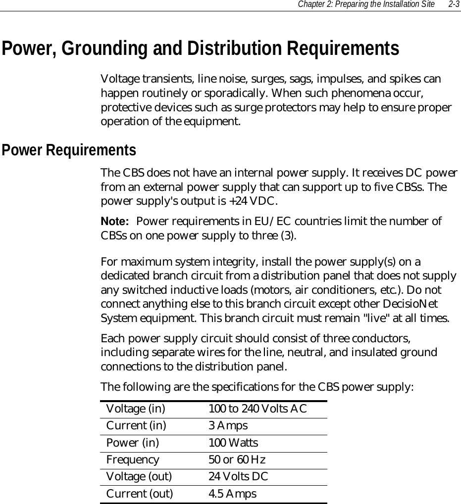
![2-6 Chapter 2: Preparing the Installation SiteEnvironmental RequirementsDecisioNet components operate across a wide range of environmentalconditions as shown in the following tables. Do not install thesecomponents in locations where the temperature or humidity may gobeyond the limits indicated.Due to lower atmospheric pressure and air rarefaction at highaltitudes, the maximum dry bulb temperature for each working rangeis decreased linearly by a value of 3.3 °C /1,000m (1.8 °F /1,000 ft.)between the altitude of 500m (1,640 ft.) and 3,000 m (9,840 ft.).Temperature and HumidityThe environmental requirements for the CBS and ESLs are shown inthe following tables.CBSOperating Transit (1 week maximum) StorageTemperature(Dry bulb) 5°C to 45°C(40°F to 113°F) -40°C to 60°C(-40°F to 140°F) -10°C to 50°C(14°F to 122°F)Max. Temp.Change per Hour 10°C (18°F) 20°C (36°F) 15°C (27°F)Relative Humidity 10% to 90%No Condensation 5% to 95%No Condensation 10% to 90%No CondensationMax. HumidityChange per Hour 10% 10% 10%BarometricPressure 105 to 70 kilo pascals(up to a max. of 3,000m [9,850 ft.])105 to 70 kilo pascals(up to a max. of 3,000m [9,850 ft.])105 to 70 kilo pascals(up to a max. of 3,000m [9,850 ft.])](https://usermanual.wiki/NCR-RSD-Atlanta/7730GAI.Manual-Chapter-2/User-Guide-144930-Page-6.png)
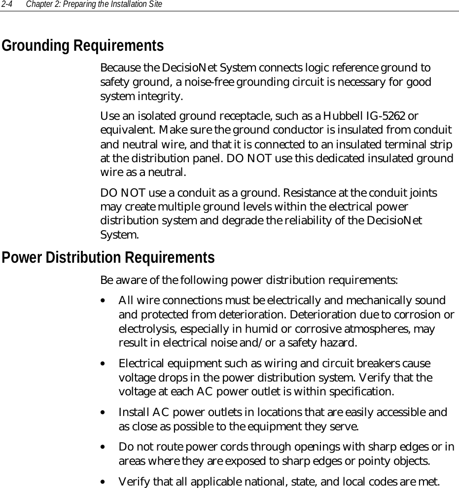
![Chapter 2: Preparing the Installation Site 2-7ESL (Standard Size and Small Size)Operating Transit (1 week maximum) andStorage (3 months maximum)Temperature(Dry bulb) 0°C to 40°C(32°F to 104°F) -30°C to 60°C(-22°F to 140°F)Max. Temp. Changeper Hour 10°C (50°F) 15°C (59°F)Relative Humidity 5% to 90%No condensation 5% to 90%No condensationMax. Humidity Changeper Hour 10%Barometric Pressure 70 kilo pascals (up to amax. of 3,000 m [9,842ft.])ESL (Freezer)Operating Transit (1 week maximum) andStorage (3 months maximum)Temperature(Dry bulb) -30°C to 10°C(-22°F to 50°F) -30°C to 60°C(-22°F to 140°F)Max. Temp. Changeper Hour 40°C (104°F) 15°C (59°F)No condensationRelative Humidity 5% to 100%Condensation 5% to 90%Max. HumidityChange per Hour 10%Barometric Pressure 70 kilo pascals (up toa max. of 3,000 m[9,842 ft.])105 kilo pascals (up to amax. of 3,000 m [9,842ft.])](https://usermanual.wiki/NCR-RSD-Atlanta/7730GAI.Manual-Chapter-2/User-Guide-144930-Page-7.png)
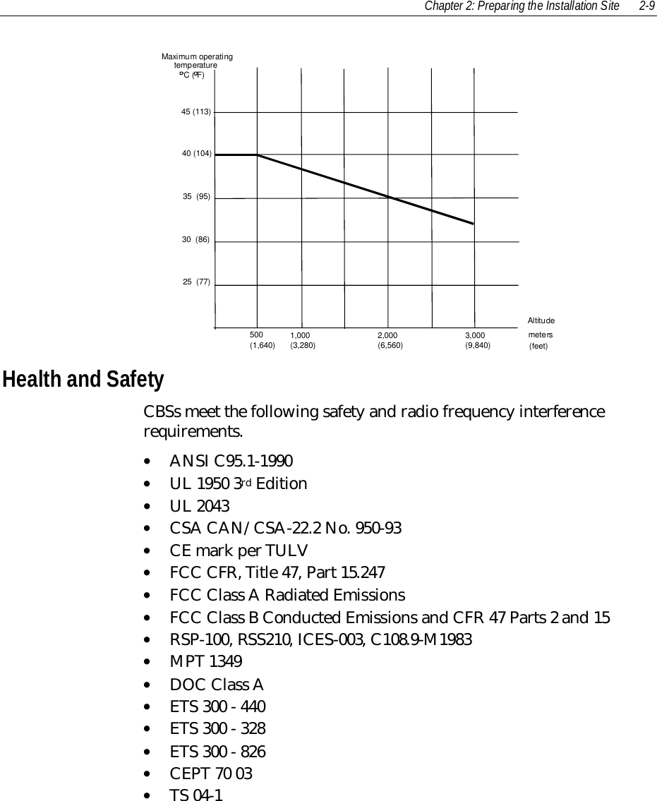
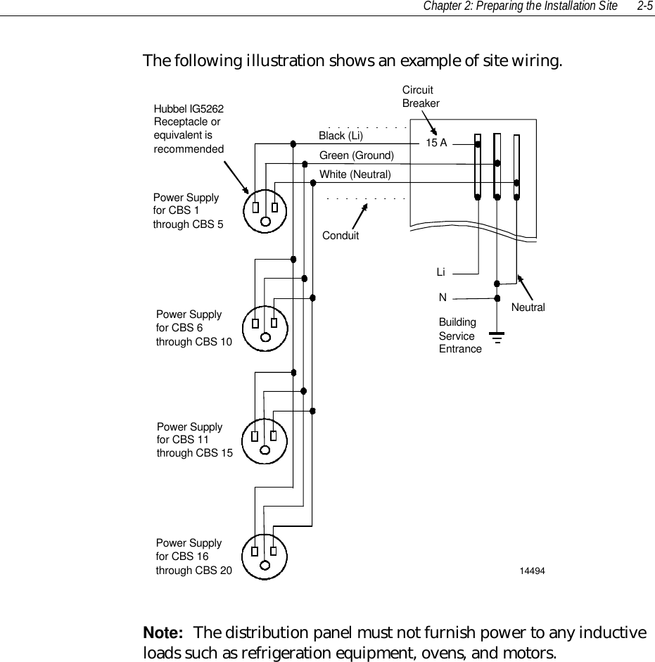
![2-8 Chapter 2: Preparing the Installation SiteESL (Signage)Operating Transit (1 week maximum) andStorage (3 months maximum)Temperature(Dry bulb) 0°C to 40°C(32°F to 104°F) -30°C to 60°C(-22°F to 140°F)Max. Temp. Changeper Hour 10°C (50°F) 15°C (59°F)Relative Humidity 5% to 90%No condensation 5% to 90%No condensationMax. Humidity Changeper Hour 10%Barometric Pressure 70 kilo pascals (up to amax. of 3,000 m [9,842ft.])Altitude and TemperatureThe following graph shows how altitude affects the operatingtemperature of CBSs and ESLs. As altitude increases, the maximumoperating temperature decreases.](https://usermanual.wiki/NCR-RSD-Atlanta/7730GAI.Manual-Chapter-2/User-Guide-144930-Page-8.png)