NCR RSD Atlanta 7730GAI Electronic Pricing Transmitter User Manual Manual Chapter 2
NCR Corporation, RSD - Atlanta Electronic Pricing Transmitter Manual Chapter 2
Contents
Manual Chapter 2

Chapter 2: Preparing the Installation Site
Preparing the Site
This chapter provides the following information:
• A summary of customer responsibilities prior to installation
• Power, grounding, and distribution requirements of the DecisioNet
System
• DecisioNet System environmental requirements
• DecisioNet System component characteristics
2

2-2 Chapter 2: Preparing the Installation Site
Customer Responsibilities
The customer must do or provide the following:
• When required by NCR, provide the NCR customer service
representative with appropriate drawings that indicate:
• Fixture Plan showing the location of store fixtures
• Floor Plan showing the location of all interior walls, ceiling
heights, and firewalls
• Site wiring diagrams for power and communication
• Location of other equipment capable of generating electrical
noise, electromagnetic interference, heat, etc.
• Environmental conditions that could affect RF communication
• Make building alterations necessary to meet wiring and other site
requirements
• Provide and install all communications cables, wall jacks, special
connectors, and associated hardware
• Provide and install necessary power distribution boxes, conduits,
grounds, lightning protection, and associated hardware
• Provide and install auxiliary power or other equipment as required
• Provide storage or service areas as required
• Make sure that the environmental requirements discussed in this
chapter are met
• Provide floor coverings and environmental systems that limit or
control static electricity build-up and discharge
Warning: Make sure all applicable codes, regulations, and laws
(including, but not limited to, electrical, building, safety, and health)
are met.
Chapter 2: Preparing the Installation Site 2-3
Power, Grounding and Distribution Requirements
Voltage transients, line noise, surges, sags, impulses, and spikes can
happen routinely or sporadically. When such phenomena occur,
protective devices such as surge protectors may help to ensure proper
operation of the equipment.
Power Requirements
The CBS does not have an internal power supply. It receives DC power
from an external power supply that can support up to five CBSs. The
power supply's output is +24 VDC.
Note: Power requirements in EU/EC countries limit the number of
CBSs on one power supply to three (3).
For maximum system integrity, install the power supply(s) on a
dedicated branch circuit from a distribution panel that does not supply
any switched inductive loads (motors, air conditioners, etc.). Do not
connect anything else to this branch circuit except other DecisioNet
System equipment. This branch circuit must remain "live" at all times.
Each power supply circuit should consist of three conductors,
including separate wires for the line, neutral, and insulated ground
connections to the distribution panel.
The following are the specifications for the CBS power supply:
Voltage (in) 100 to 240 Volts AC
Current (in) 3 Amps
Power (in) 100 Watts
Frequency 50 or 60 Hz
Voltage (out) 24 Volts DC
Current (out) 4.5 Amps

2-4 Chapter 2: Preparing the Installation Site
Grounding Requirements
Because the DecisioNet System connects logic reference ground to
safety ground, a noise-free grounding circuit is necessary for good
system integrity.
Use an isolated ground receptacle, such as a Hubbell IG-5262 or
equivalent. Make sure the ground conductor is insulated from conduit
and neutral wire, and that it is connected to an insulated terminal strip
at the distribution panel. DO NOT use this dedicated insulated ground
wire as a neutral.
DO NOT use a conduit as a ground. Resistance at the conduit joints
may create multiple ground levels within the electrical power
distribution system and degrade the reliability of the DecisioNet
System.
Power Distribution Requirements
Be aware of the following power distribution requirements:
• All wire connections must be electrically and mechanically sound
and protected from deterioration. Deterioration due to corrosion or
electrolysis, especially in humid or corrosive atmospheres, may
result in electrical noise and/or a safety hazard.
• Electrical equipment such as wiring and circuit breakers cause
voltage drops in the power distribution system. Verify that the
voltage at each AC power outlet is within specification.
• Install AC power outlets in locations that are easily accessible and
as close as possible to the equipment they serve.
• Do not route power cords through openings with sharp edges or in
areas where they are exposed to sharp edges or pointy objects.
• Verify that all applicable national, state, and local codes are met.
Chapter 2: Preparing the Installation Site 2-5
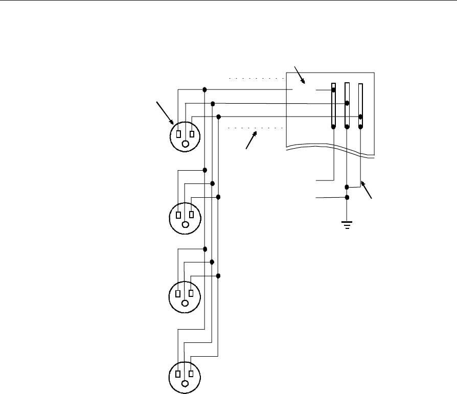
The following illustration shows an example of site wiring.
14494
15 A
Circuit
Breaker
Conduit
Li
NNeutral
Building
Service
Entrance
Power Supply
for CBS 6
through CBS 10
Power Supply
for CBS 1
through CBS 5
Hubbel IG5262
Receptacle or
equivalent is
recommended Black (Li)
Green (Ground)
White (Neutral)
Power Supply
for CBS 11
through CBS 15
Power Supply
for CBS 16
through CBS 20
Note: The distribution panel must not furnish power to any inductive
loads such as refrigeration equipment, ovens, and motors.
2-6 Chapter 2: Preparing the Installation Site
Environmental Requirements
DecisioNet components operate across a wide range of environmental
conditions as shown in the following tables. Do not install these
components in locations where the temperature or humidity may go
beyond the limits indicated.
Due to lower atmospheric pressure and air rarefaction at high
altitudes, the maximum dry bulb temperature for each working range
is decreased linearly by a value of 3.3 °C /1,000m (1.8 °F /1,000 ft.)
between the altitude of 500m (1,640 ft.) and 3,000 m (9,840 ft.).
Temperature and Humidity
The environmental requirements for the CBS and ESLs are shown in
the following tables.
CBS
Operating Transit (1 week maximum) Storage
Temperature
(Dry bulb) 5°C to 45°C
(40°F to 113°F) -40°C to 60°C
(-40°F to 140°F) -10°C to 50°C
(14°F to 122°F)
Max. Temp.
Change per Hour 10°C (18°F) 20°C (36°F) 15°C (27°F)
Relative Humidity 10% to 90%
No Condensation 5% to 95%
No Condensation 10% to 90%
No Condensation
Max. Humidity
Change per Hour 10% 10% 10%
Barometric
Pressure 105 to 70 kilo pascals
(up to a max. of 3,000
m [9,850 ft.])
105 to 70 kilo pascals
(up to a max. of 3,000
m [9,850 ft.])
105 to 70 kilo pascals
(up to a max. of 3,000
m [9,850 ft.])
Chapter 2: Preparing the Installation Site 2-7
ESL (Standard Size and Small Size)
Operating Transit (1 week maximum) and
Storage (3 months maximum)
Temperature
(Dry bulb) 0°C to 40°C
(32°F to 104°F) -30°C to 60°C
(-22°F to 140°F)
Max. Temp. Change
per Hour 10°C (50°F) 15°C (59°F)
Relative Humidity 5% to 90%
No condensation 5% to 90%
No condensation
Max. Humidity Change
per Hour 10%
Barometric Pressure 70 kilo pascals (up to a
max. of 3,000 m [9,842
ft.])
ESL (Freezer)
Operating Transit (1 week maximum) and
Storage (3 months maximum)
Temperature
(Dry bulb) -30°C to 10°C
(-22°F to 50°F) -30°C to 60°C
(-22°F to 140°F)
Max. Temp. Change
per Hour 40°C (104°F) 15°C (59°F)
No condensation
Relative Humidity 5% to 100%
Condensation 5% to 90%
Max. Humidity
Change per Hour 10%
Barometric Pressure 70 kilo pascals (up to
a max. of 3,000 m
[9,842 ft.])
105 kilo pascals (up to a
max. of 3,000 m [9,842
ft.])
2-8 Chapter 2: Preparing the Installation Site
ESL (Signage)
Operating Transit (1 week maximum) and
Storage (3 months maximum)
Temperature
(Dry bulb) 0°C to 40°C
(32°F to 104°F) -30°C to 60°C
(-22°F to 140°F)
Max. Temp. Change
per Hour 10°C (50°F) 15°C (59°F)
Relative Humidity 5% to 90%
No condensation 5% to 90%
No condensation
Max. Humidity Change
per Hour 10%
Barometric Pressure 70 kilo pascals (up to a
max. of 3,000 m [9,842
ft.])
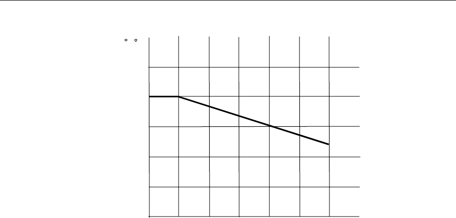
Altitude and Temperature
The following graph shows how altitude affects the operating
temperature of CBSs and ESLs. As altitude increases, the maximum
operating temperature decreases.
Chapter 2: Preparing the Installation Site 2-9
Maximum operating
temperature
C ( F)
500 1,000
(3,280)(1,640)
2,000
(6,560)
3,000
(9,840)
45 (113)
40 (104)
35 (95)
30 (86)
25 (77)
Altitude
meters
(feet)
Health and Safety
CBSs meet the following safety and radio frequency interference
requirements.
• ANSI C95.1-1990
• UL 1950 3rd Edition
• UL 2043
• CSA CAN/CSA-22.2 No. 950-93
• CE mark per TULV
• FCC CFR, Title 47, Part 15.247
• FCC Class A Radiated Emissions
• FCC Class B Conducted Emissions and CFR 47 Parts 2 and 15
• RSP-100, RSS210, ICES-003, C108.9-M1983
• MPT 1349
• DOC Class A
• ETS 300 - 440
• ETS 300 - 328
• ETS 300 - 826
• CEPT 70 03
• TS 04-1
2-10 Chapter 2: Preparing the Installation Site
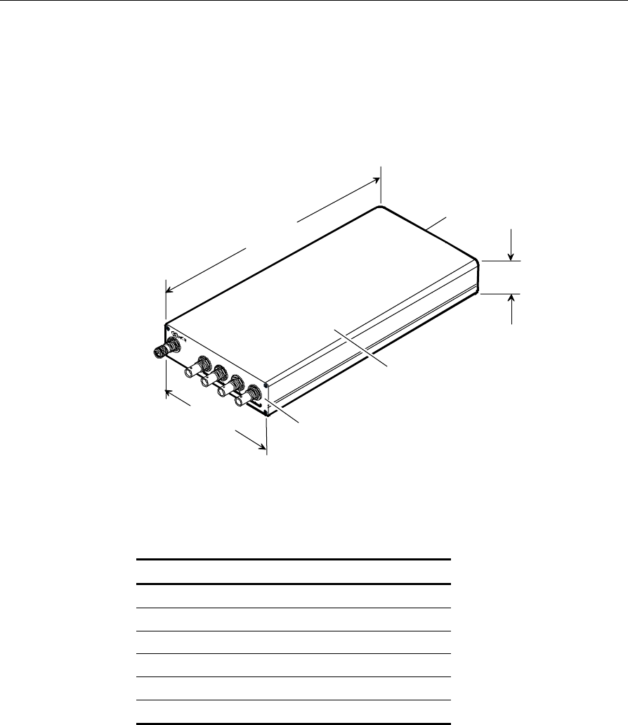
Component Characteristics
CBS
The CBS weighs 1.13 kg (2.5 lb.). The following illustration shows the
dimensions of the CBS.
287.3 mm
(11.31 in.)
140.4 mm
(5.53 in.)
38.6 mm
(1.52 in.)
Front
Top
Back
..
.
18827
The CBS does not have ventilation holes, but it does require the service
clearances indicated in following table.
Direction Distance in mm Distance in inches
Top Not applicable Not applicable
Bottom 127 5
Right 101.6 4
Left 101.6 4
Front 101.6 4
Back 101.6 4
Chapter 2: Preparing the Installation Site 2-11
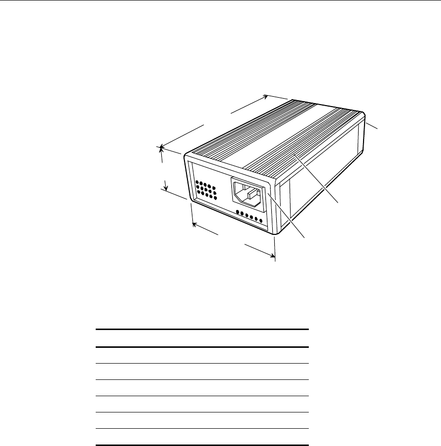
CBS Power Supply
The CBS power supply weighs .85 kg (1.88 lb.). The following
illustration shows the dimensions of the CBS power supply.
17069
96 mm
(3.8 in.)
48.8 mm
(1.9 in.)
179 mm
(7 in.)
Front
Top
Back
The CBS power supply has rear ventilation holes, so it requires the air
flow and service clearances indicated in the following table.
Direction Distance in mm Distance in inches
Top 50.8 2
Bottom 50.8 2
Right 50.8 2
Left 50.8 2
Front 50.8 2
Back 50.8 2
2-12 Chapter 2: Preparing the Installation Site
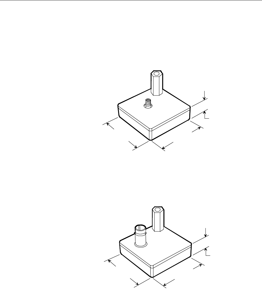
Antennas
Transmit Antenna
The transmit antenna has a threaded female standoff and weighs .085
kg (0.19 lb.). The following illustration shows the dimensions of the
transmit antenna.
17100
13 mm
.5 in.
45 mm
1.75 in.
45 mm
1.75 in.
Receive Antenna
The receive antenna has a threaded female standoff and weighs .085 kg
(0.19 lb.). The following illustration shows the dimensions of the
receive antenna.
17065
13 mm
.5 in.
45 mm
1.75 in.
45 mm
1.75 in.
Chapter 2: Preparing the Installation Site 2-13
ESLs
ESLs are available in variety of sizes and LCDs. This section describes
the physical characteristics of the available ESLs.
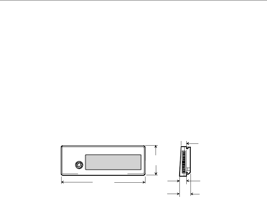
ESL, Standard Size
The 1x8 and 4+8-character standard-size ESLs weigh 0.031 kg (0.068
lb.). Physical dimensions are shown below.
Standard-size 1x8 and 4+8-character "freezer" ESLs are available at
GCA. They have the same dimensions and weight as non-freezer
standard-size ESLs. The text on the serial number label of the freezer
ESL is blue. The text on the serial number label of the non-freezer ESL
is black.
18868
94 mm
(3.70 in.)
35 mm
(1.38 in.)
9.52 mm
(.37 in.)
14.02 mm
(.55 in.)
7.5 mm
(.29 in.)
2-14 Chapter 2: Preparing the Installation Site
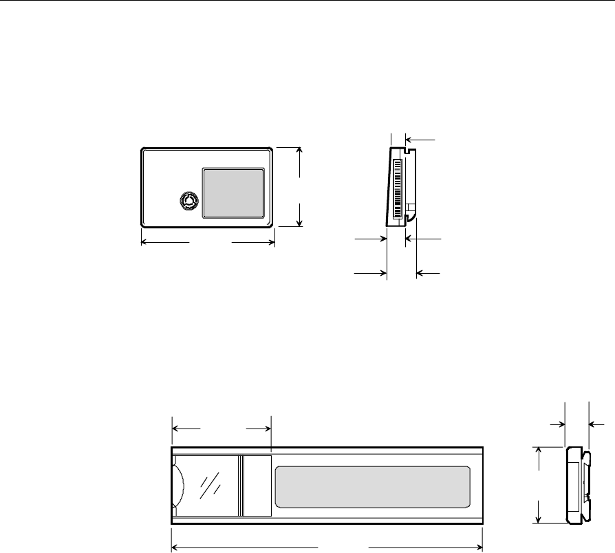
ESL, Small Size
The 2x5-character small size ESL weighs 0.023 kg (0.05 lb.). Physical
dimensions are shown below.
18869
60 mm
(2.36 in.)
35 mm
(1.38 in. )
9.52 mm
(.37 in.)
14.02 mm
(.55 in.)
7.5 mm
(.29 in.)
ESL, Small Signage
The 1x6-character small signage ESL weighs 0.068 kg (0.15 lb.).
Physical dimensions are shown below.
17062
58.3 mm
(2.3 in.)
160 mm
(6.3 in.)
14.1 mm
(.56 in.)
45 mm
(1.7 in.)
Chapter 2: Preparing the Installation Site 2-15
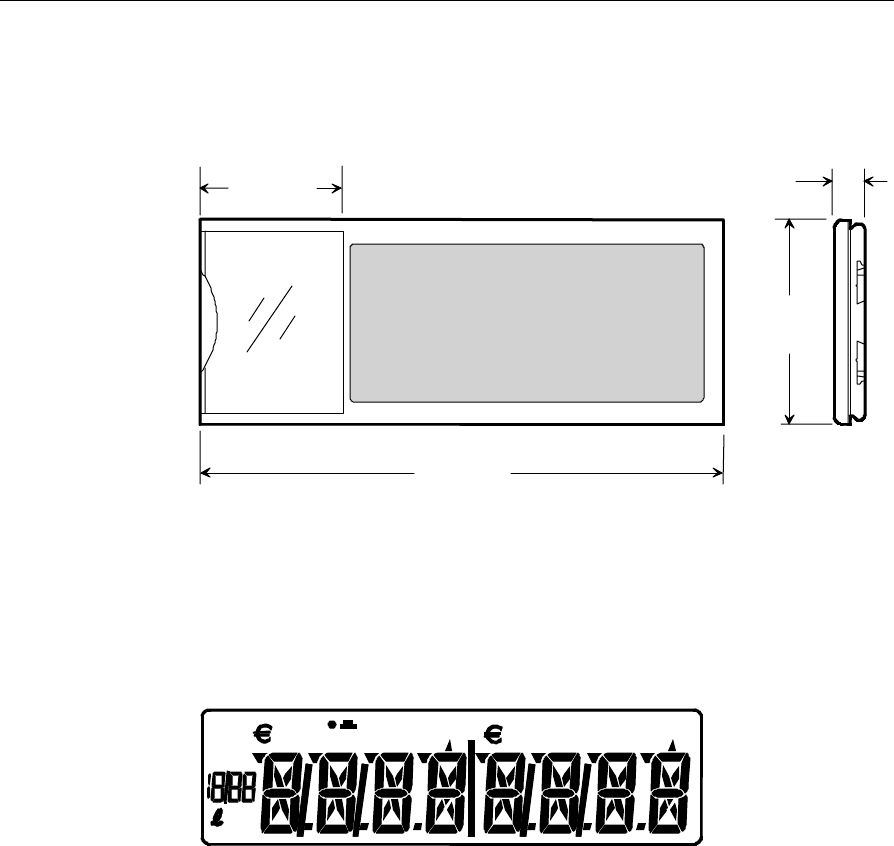
ESL, Large Signage
The 2x6-character large signage ESL weighs 0.16 kg (0.36 lb.). Physical
dimensions are shown below.
58.2 mm
(2.3 in.)
216 mm
(8.5 in.)
84.5 mm
(3.33 in.)
12.5 mm
(.49 in.)
18870
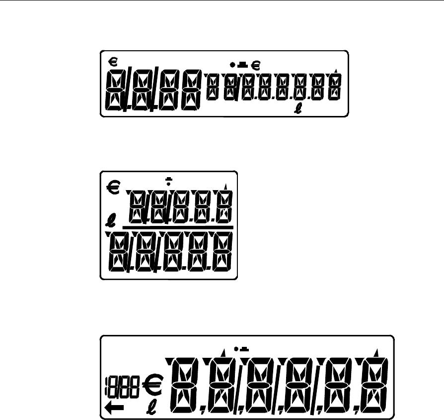
ESL Displays and Symbols
The ESL displays are shown in the following illustrations. The symbols
on the displays are explained in the table following the illustrations.
1x8-Character, Standard Size
18871
kg
SALE
ENDS
2-16 Chapter 2: Preparing the Installation Site
4+8-Character, Standard Size
18872
PROMO kg
2x5-Character, Small Size
18873
SALE ENDS
kg
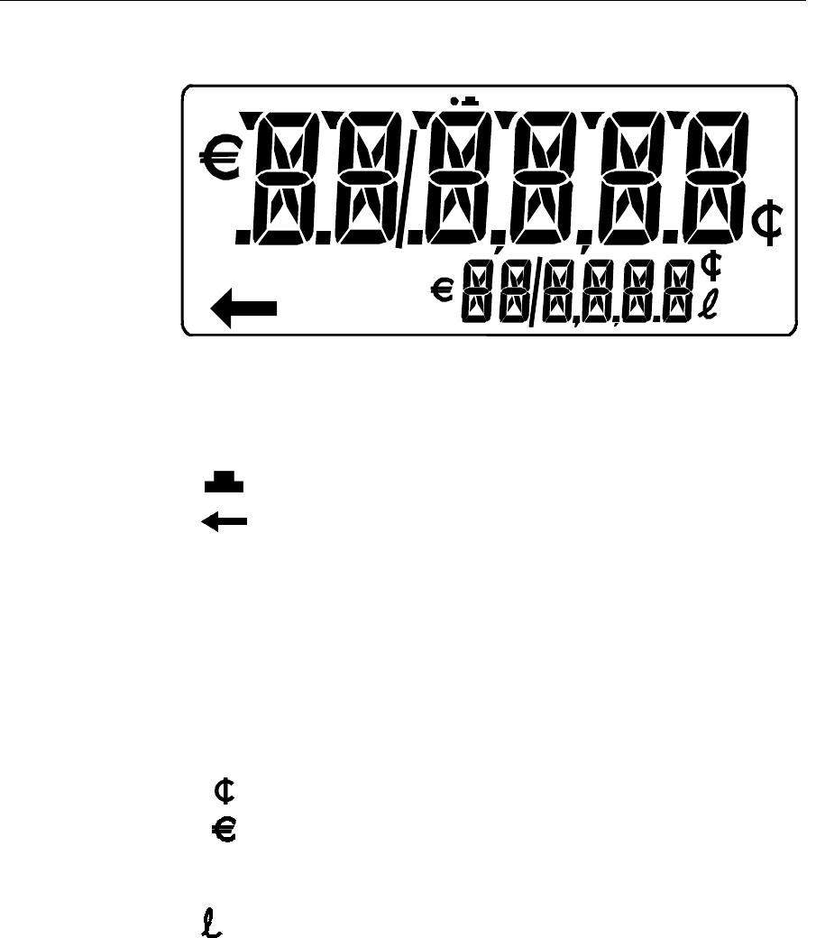
1x6-Character, Small Signage
18874
kg
SALE
ENDS
Chapter 2: Preparing the Installation Site 2-17
2x6-Character, Large Signage
18875
PROMO SALE ENDS
UNIT PRICE kg
●Lights when the ESL is out of synchronization for RF
communication
Lights when the battery is low
Customer defined symbol
(Accessible from the Promotions option in ESL
Maintenance or from a custom application)
UNIT Customer defined symbol
PRICE Customer defined symbol
SALE Customer defined symbol
ENDS Customer defined symbol
PROMO Customer defined symbol
Cents currency symbol
Euro currency symbol
kg Kilogram symbol
Liter symbol

2-18 Chapter 2: Preparing the Installation Site
For ESL configuration information refer to the DecisioNet User's Guide
(B005-0000-1317).