NCR RSD Atlanta 7730GAI Electronic Pricing Transmitter User Manual Manual Chapter 3
NCR Corporation, RSD - Atlanta Electronic Pricing Transmitter Manual Chapter 3
Contents
Manual Chapter 3

Chapter 3: Installing the Hardware Infrastructure
Chapter Overview
This chapter describes how to install the DecisioNet hardware
infrastructure. This includes the following components:
• CBSs
• CBS power supplies
• Data and power cables
• Transmit and receive antennas
For information about ordering these parts, refer to Appendix A.
After the DecisioNet hardware is installed, the DecisioNet software
must be configured and the site must be RF certified. For configuration
information, refer to "Chapter 6: Configuring the DecisioNet System
Environment" in this guide and the "Certify RF Infrastructure" section
of the DecisioNet Implementation Guide (B005-0000-1250).
3

3-2 Chapter 3: Installing the Hardware Infrastructure
Installation Recommendations
• The most efficient way to install the DecisioNet hardware
infrastructure is in one pass through the store. Install the CBSs,
antennas, power cables, and data cables all at the same time
• Label all cables and document labeling for future reference.
• Neatness makes servicing the system much easier.
• Allow slack in cables, especially in receive antenna cables.
• Test the system as it is being installed. Refer to Chapter 7, "Testing
and Troubleshooting," for information on testing.
• Provide AC power that meets NCR requirements for the power
supplies.
• Test wiring as it is installed. Some installation problems are
extremely difficult to diagnose later.
• DecisioNet Release 3.0 requires the RF infrastructure to be
connected to the site's DecisioNet Software Controller to test the
infrastructure. Refer to the following for information on testing the
infrastructure and site certification:
• DecisioNet Implementation Guide (B005-0000-1250)
• DecisioNet RF Certification Utility Guide
• Certification/Re-Certification Site Survey Policy (497-0410343)

Chapter 3: Installing the Hardware Infrastructure 3-3
General Layout Instructions
• The cable length between any two devices (hub to CBS or CBS to
CBS) cannot exceed 100 m (328 ft.).
• The maximum number of Ethernet levels beyond the primary CBS
is three (3).
• The maximum total cable length is as follows:
Cable
Maximum Cable Length
Ethernet (primary CBS to last CBS in
chain)
300 m (984 ft.)
Power supply to last CBS in the chain
162 m (532 ft.)
• Use only NCR authorized communication cable.
• Communication cables must be secure and locked into their
connectors.
• The maximum number of CBSs per store is 40 except for model
7730-1013-9090 (Netherlands) which has a maximum of 12 CBSs
per store.
• If the communication cable is routed through an elevator shaft, it
must be in a conduit and the conduit must be connected to the
building ground.
• The minimum distance between a communication cable and a
fluorescent, neon, or incandescent light is 30 cm (12 in.).
Note: The minimum distance from red blown neon-type signs is 9.1 m
(30 ft.). See the “Neon Signs” section in Chapter 2 of the DecisioNet
Implementation Guide for information.
• All communication cable connections must be protected from
electrical and mechanical deterioration. The deterioration of
communication cable connections due to corrosion or electrolysis,
especially in a humid or corrosive atmosphere, may result in
electrical noise.

3-4 Chapter 3: Installing the Hardware Infrastructure
• The minimum distances between a communication cable and
electrical equipment/associated power cables are as follows:
Maximum Rated
Circuit Power
Unshielded Power
Cables
Shielded Power
Cables
1 kVA
30.5 cm (14 in.)
2.54 cm (1 in.)
2 kVA
45.7 cm (18 in.)
5.08 cm (2 in.)
5 kVA
60.9 cm (24 in.)
15.24 cm (6 in.)
Over 5 kVA
152.4 cm (60 in.)
30.48 cm (12 in.)
• All interconnecting wiring between the Ethernet hub, CBSs, and
power supplies is low voltage wiring. This wiring must conform to
all local and national electrical codes for the routing of commercial
signal wire.
• Do not route communication cables outside the building.
Tools and Supplies
DecisioNet infrastructure installers must have access to the tools
typically found in an electrician's tool box. Additional tools and
supplies an installation team may require are shown in the following
table.
Tool/Supply
Quantity
Cable ties
10 per CBS
RJ45 Modular Jacks
2 per cable plus spares
Ideal Modular RJ45 crimp kit
1
Milwaukee 2.4 V low-torque electric screw
driver
1
ESL removal tool
1 per installer
Lift truck
1
Ideal LinkMaster CAT5 cable tester
Ideal Cat. No. 62-200
1
Chapter 3: Installing the Hardware Infrastructure 3-5
CBS Installation
The following sections describe the preparation, cabling, and
installation of the CBS and its related components.
CBS Ethernet Cable Connections
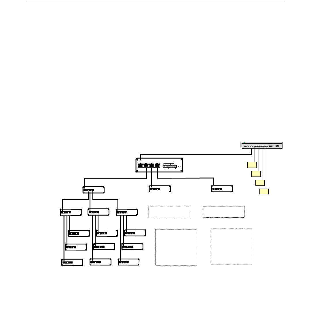
The Release 3.0 CBS uses a star topology and has an integrated
Ethernet hub that can connect to three other CBSs. DecisioNet III
supports up to three (3) levels below the primary CBS. This topology
results in the 40 CBS maximum mentioned in the General Layout
Guidelines section. The following illustration shows an example 40 CBS
configuration, its Ethernet cable connections, and the maximum
number of CBSs on each level.
Ethernet Hub
WS
WS
WS
WS
Level 1
Level 2
Level 3
Primary CBS
In Out
8765432187654321 8765432187654321
Out Out In Out
8765432187654321 8765432187654321
Out Out In Out
8765432187654321 8765432187654321
Out Out
In Out
8765432187654321 8765432187654321
Out Out
In Out
87654321
87654321 87654321
87654321
Out Out In Out
8765432187654321 8765432187654321
Out Out
In Out
8765432187654321 8765432187654321
Out Out
In Out
87654321
87654321 87654321
87654321
Out Out
In Out
8765432187654321 8765432187654321
Out Out
In Out
8765432187654321 8765432187654321
Out Out
In Out
8765432187654321 8765432187654321
Out Out
In Out
8765432187654321 8765432187654321
Out Out
In Out
87654321
87654321 87654321
87654321
Out Out
In Out
8765432187654321 8765432187654321
Out Out
In Out
8765432187654321 8765432187654321
Out Out
( 3 CBSs)
( 9 CBSs)
( 27 CBSs)
CBS 24-26
CBS 1
CBS 27-29
CBS 40-48 CBS 49-57
11 12 13
21 22 23
31 32 33
34 35 36
37 38 39
18885
Power
Uplink
D DDDCCCC
12 3
Ground
+24VDC

3-6 Chapter 3: Installing the Hardware Infrastructure
CBS Numbering
CBS’s are identified in the CBS Manager section of the DecisioNet CBS
configuration file (DNCBSCONFIG.XML) with a unique number (1-99)
and a host name or IP address. Using the numbering scheme shown in
the illustration helps identify the level in which the CBS is connected in
the topology when running diagnostic tests and analyzing diagnostic
logs. This scheme is as follows:
• Primary CBS = always 1
• Level 1 = CBS 11-13
• Level 2 = CBS 21-29
• Level 3 = CBS 31-57
CBS configuration details are described the “Setting the CBS IP
Address” section of Chapter 6, Configuring the DecisioNet System
Environment.
Chapter 3: Installing the Hardware Infrastructure 3-7
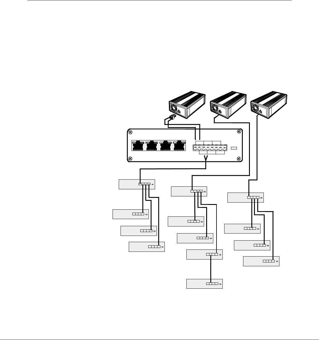
CBS Power Supply Cable Connections
The CBS Power Supply can support up to five (5) CBSs, however,
power requirements in EU/EC countries limit the number of CBSs
connected to a power supply to three (3). The following illustration
shows an example power supply wiring scheme for a 14 CBS non-
EU/EC configuration.
18886
CBS Power Supplies
Level 1
Level 2
Primary CBS Power
Uplink
DDDDCCCC
12 3
Ground
+24VDC
Level 3
3-8 Chapter 3: Installing the Hardware Infrastructure
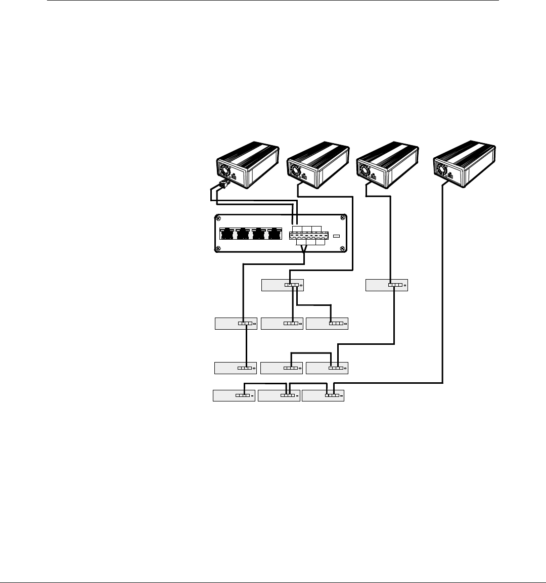
EU/EC Installations
Power requirements in EU/EC countries limit the number of CBSs
connected to a power supply to three (3). The following illustration
shows power supply cable connections for a 12 CBS configuration
using 4 power supplies. This cabling scheme may be extended to
support 40 CBSs.
18887
Level 1
Level 2
Level 3
Primary CBS Power
CBS Power Supplies
+24VDC
Ground
Uplink
DDD DCCCC
12 3
Chapter 3: Installing the Hardware Infrastructure 3-9
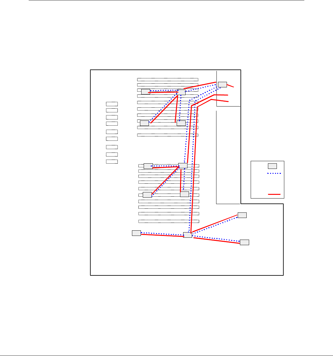
Sample Store Cabling
The following illustration shows a non-EU/EC country store layout
with 13 CBSs and 3 power supplies. Ethernet and power supply cables
originate in the back office and are bundled together to accomplish this
configuration.
18961
Back
Office
Produce Meat and Deli
Dairy
Bakery
Checkout
1
11
12
13
2322
21
24
25 26
27
28
29
PS1
PS2
PS3
27
Legend
CBS
Power
Supply
Cable
Cable
PS1

3-10 Chapter 3: Installing the Hardware Infrastructure
CBS Cables
The following cables are supplied by NCR.
Cable ID
(Part Number) Description Length
m (ft.) Connect From Connect To Comments
1424-Cxxx-0018
(230-0146539) Transmit
antenna cable
(plenum rated)
1.8 (5.9)CBS transmit
antenna connector Transmit antenna TNC screw-on
connector
1424-C057-0180
(230-0134951) Receive
antenna cable
(plenum rated)
18 (59) CBS receive
antenna connector
A, B, C, or D
Receive antenna BNC connector
1416-C520-0150
(230-0134953) Receive
antenna cable
(plenum rated)
15 (49) CBS receive
antenna connector
A, B, C, or D
Receive antenna BNC connector
1416-C463-9999
(497-0413234) CBS power
supply pigtail CBS power supply AWG 14/2 bulk
cable Included with
power supply kit
CBS power supply
pigtail First of up to five
CBSs
Bulk cable
from
third-party
Power cable
CBS CBS
Refer to tables in
next section
CBS CBSBulk cable
from
third-party
Data cable Refer to tables in
next section
Note: All cables conform to type CL2P.

Chapter 3: Installing the Hardware Infrastructure 3-11
Power and Data Cables
The power and data cables must be purchased in bulk from a third
party. NCR recommends using the Belden cables described in the
following table. Comparable cables from other manufacturers are
acceptable.
The wire colors referenced in the text and illustrations that follow are
consistent with the recommended Belden cables. If you are using a
comparable cable from another manufacturer, your wire colors may be
different.
Cable Use Manufacturer Manufacturer
Part Number Description
Power Belden 6100UE 2 conductor, 14 AWG stranded,
unshielded, plenum rated
Power Belden 5100UE 2 conductor, 14 AWG stranded,
unshielded, non-plenum rated
Data Belden 1585A 4 pair, CAT5, 24 AWG solid,
unshielded, plenum rated
Data Belden 1583A 4 pair, CAT5, 24 AWG solid,
unshielded, non-plenum rated
Note: When installing into a plenum type ceiling, plenum rated wire
may be required by local or national electrical codes. Most suspended
ceilings are considered plenums; open ceilings are not. Plenum rated
wire typically costs twice as much as non-plenum. Choose the correct
wire type based on your applicable local and national electrical codes.
For general reference, CBS wiring falls under NEC (National Electrical
Code) Class 2 type.

3-12 Chapter 3: Installing the Hardware Infrastructure
Power Cable Connectors
Each CBS is shipped with a 4-wire connector that plugs into the 8-wire
power receptacle. The only tool required to install the power cable into
the connector is a small screwdriver.
Data Cable Connectors
An RJ45 connector is required for each of the CBSs data connectors.
The RJ45 connectors must be purchased from a third party. A crimp
tool is required to install the data cable into the RJ45 connector.
The following table provides information about RJ45 connectors and
crimp tools.
Manufacturer Manufacturer
Part Number Quantity Description
AMP 5-557315-1
5-557315-2
5-557315-3
5-557315-4
10,000 (loose)
500 (loose)
1,000 (10 boxes of 100)
1,000 (40 bags of 25)
RJ45, 8-position,
unshielded type1
AMP 1-231666-1 1 Crimp tool2
Ideal 33-652 1 Crimp tool2
Ideal 30-560 1 AMP die for Ideal
crimp tool3
1 Use any comparable RJ45 connector compatible with your crimp tool.
2 Use any crimp tool compatible with your RJ45 connector.
3 Necessary only when using AMP connectors and Ideal crimp tool.
Chapter 3: Installing the Hardware Infrastructure 3-13
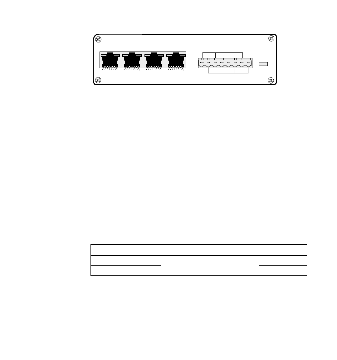
CBS Connectors and Status Lights
18877
87654321
12 453678
Uplink
DDDDCCCC
12 3 +24VDC
Ground
Power
87654321 87654321 87654321
Data Connectors
The CBS has four data connectors:
Uplink – used to connect the in-store hub or a higher level CBS hub
1, 2 and 3 – used for downlink connections to lower level CBS hubs
Data connector pin and signal use is as follows:
• Pins 1, 2, 3, and 6 carry standard Ethernet transmit and receive data
between the Ethernet Hub and the primary CBS and between all
CBS's as defined in ISO/IEC Standard 8802.3 paragraph 14.5.1.
• Pins 4, 5, 7, and 8 are used for DecisioNet transmit and receive
timing signals between all CBS’s.
Power Receptacle
The following table provides information about the CBS power
receptacle.
Pins Description Connection Belden Wire Color
1, 3, 5, 7 +24 VDC White
2, 4, 6, 8 Ground From CBS power supply to
primary CBS, and CBS to CBS Black

3-14 Chapter 3: Installing the Hardware Infrastructure
CBS Status Lights
The Ethernet status lights (LEDs) are in the top corners of the data
connectors. The Power status light is a red LED shown to the right of
the power receptacle in the previous illustration.
The CBS status lights indicate the following conditions.
LED State Meaning
On OK (power is on)
Off PROBLEM (no power)
Power (red)
Blinking PROBLEM (intermittent power)
On OK (good link)
Off PROBLEM (no link)
C (green)
Ethernet link
status Blinking PROBLEM (intermittent link)
On NOT DEFINED
Off PROBLEM (no receive activity)
D (yellow)
Ethernet
activity Blinking OK (receive activity)
Chapter 3: Installing the Hardware Infrastructure 3-15
CBS Identification
NCR Corporation Made in U.S.A
Class:
Model:
Part Number:
Date of Mfg:
Serial #:
MAC Address:
24 VDC 0.5A
7730
1011
497-1234567
May 2001
50-1234567
080001357942
19015
The CBS product label identifies the model number, serial number, and
unique MAC address of the CBS. The last 6 hexadecimal characters of
the MAC address are used to specify the hostname for each CBS in the
CBS Manager section of the DecisioNet CBS Configuration file
(DNCBSCONFIG.XML). The hostname format is NCRDNETXXXXXX
where XXXXXX is the 6 characters from the MAC address.
When you complete the RF infrastructure installation, you need to
assign IP addresses and verify CBS communications. Refer to "CBS
Hardware Configuration" section at the end of this chapter for details
about assigning CBS addresses in your Ethernet network. How to enter
the CBS configuration information in the CBS Configuration File is
described in the “Setting the CBS IP Address” section of Chapter 6,
Configuring the DecisioNet System Environment.
3-16 Chapter 3: Installing the Hardware Infrastructure
CBS Installation
Install the CBSs at the same time you install the power cables, data
cables, and antennas. The most efficient way to install the DecisioNet
hardware is in one pass through the store.
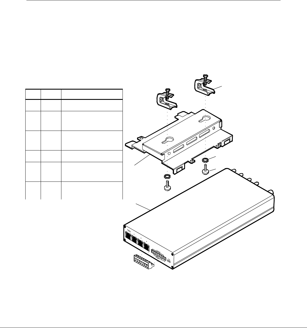
The following table and illustration show the CBS and associated
hardware.
18879
2
1
4
5
3
The CBS can be mounted in any position. The mounting bracket and
universal beam clamps permit a wide variety of installations. Position
the CBS for easy LED and connector access. The following example
illustrations show a CBS mounted to a roof truss.
Item Quantity Description
11 CBS
21 CBS mounting
bracket
3 2 Universal beam
clamp
42 Lock washer
5 2 Screw (¼ -20 x ¼
Phillips head)
62 Power connector
(installed on CBS )
Chapter 3: Installing the Hardware Infrastructure 3-17
18829
ABCD
Transmit
Receive
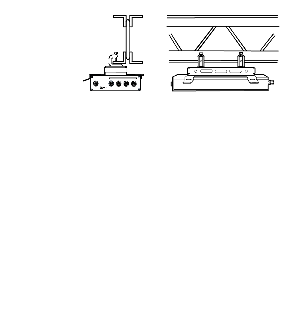
Warning: The CBS must be mounted securely and installed in
accordance with local building codes. The mounting surface must be
able to withstand a minimum weight of 2.26 kg (5 lbs.).
Caution: DO NOT install a CBS by placing it on a ceiling tile.
The following steps describe a typical installation in which a CBS is
mounted to a roof truss as shown in the previous illustration.
1. Use the screws and lock washers to secure the clamps to the
mounting bracket.
Caution: Vibrations could loosen the screws holding the mounting
bracket to the clamps. It is extremely important to place the lock
washers on the screws before installing the screws into the clamps.
2. Position the clamps on the roof truss and tighten the clamp screws.
3. Install the CBS into the mounting bracket.
Caution: To prevent damage to the transmitter, the transmit antenna
must be connected to the CBS before power is applied to the CBS.
3-18 Chapter 3: Installing the Hardware Infrastructure
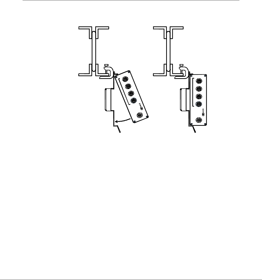
Preferred CBS Mounting Solution
1.
ABCD
Transmit
Receive
ABCD
Transmit
Receive
19014
2.
1. Attach the CBS Mounting Bracket to the universal beam clamp
using the phillips head screws and the tabs on the side of the CBS
Mounting Bracket.
2. Attach the clamp to the beam.
3. Insert the CBS as shown in figures 1 and 2.
Connecting Ethernet Data Cables
From the primary CBS, a data cable connects every secondary CBS in
the system as shown previously in “CBS Ethernet Cable Connections”
section. Note that the Uplink data connector is used to connect to a
higher level CBS and the data connectors 1, 2, and 3 are used to connect
to lower level CBSs.
Connecting the Ethernet Hub to the Primary CBS
Each store configuration has only one primary CBS. All other CBSs are
secondary CBSs. The primary CBS is the one connected directly to the
Chapter 3: Installing the Hardware Infrastructure 3-19
Ethernet Hub. Standard 4 pair, CAT5, 24 AWG solid, unshielded,
plenum rated cables are required for all Ethernet communications.
1. Locate the Ethernet hub.
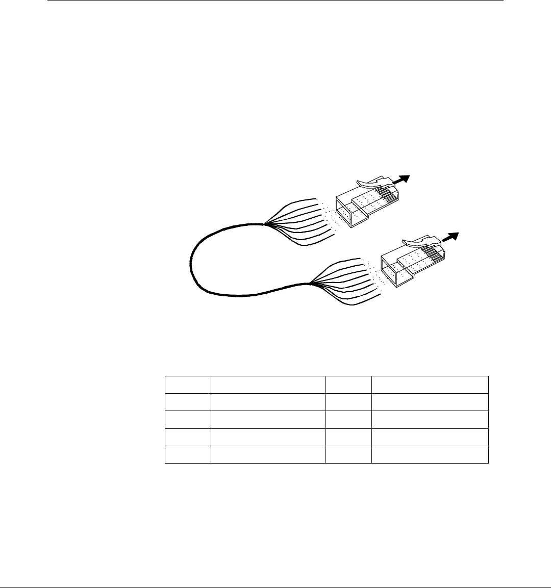
2. Cut a length of data cable that is long enough to reach from the hub
to the primary CBS.
3. On each end of the data cable, install the wires into an RJ45
connector as shown in the following illustration and then crimp the
connector onto the cable.
18959
To Ethernet Hub
or CBS III Hub
To CBS III
Hub
RJ45
Connector
Blue/White
Orange
Orange\White
Green
RJ45
Connector
8
1
1
8
Note: Colors shown are for recommended Belden
cables. Your wire colors may be different.
Blue/White
Orange
Orange\White
Green
Blue
Blue
Green/White
Green/White
Brown
Brown
Brown/White
Brown/White
Belden Wire Colors
RJ45 Pin Color RJ45 Pin Color
1Orange 5Blue
2 Orange/White 6 Green/White
3Green 7Brown
4 Blue/White 8 Brown/White
4. Plug the data cable into the Uplink data connector on the primary
CBS.

3-20 Chapter 3: Installing the Hardware Infrastructure
Connecting Secondary CBSs
Follow these steps to connect the secondary CBSs:
1. Cut a length of data cable that is long enough to reach from one
CBS to the next CBS.
2. On each end of the data cable, install the wires into an RJ45
connector as shown in the previous illustration and then crimp the
connector onto the cable.
3. Plug the RJ45 connector into data connector 1, 2 or 3 and into the
Uplink data connector of the next CBS.
4. Repeat steps 1 – 3 until all secondary CBSs are linked by a data
cable.

Chapter 3: Installing the Hardware Infrastructure 3-21
Connecting Power Supply Cables
Refer to the illustrations in the “CBS Power Supply Cable Connections”
section. Power supply cable routing is store dependent. The power
connector provides flexibility to connect additional CBSs in series from
one CBS to another or in parallel from a CBS to three other CBSs.
Connecting CBS Power Supplies to AC Power
Place the CBS power supplies with the host computer system, if
possible. Plug all power supplies into a common power strip so that
you can power them on and off at the same time for reset purposes.
In some cases, cable length restrictions may prevent you from
installing all power supplies in the same location. In this case, you
need to install a separately switched AC main circuit so that you can
still control the power supplies at the same time. If local electrical
codes or special circumstances require you to install more than one
switched AC main circuit for the power supplies, all the main circuit
switches should be in the same easily accessible location.
Do not install the CBS power supply in the ceiling.
1. Have an electrician install new AC receptacles if needed.
2. Do not plug the CBS power supply into an AC receptacle until
steps 1 – 6 in the next section are complete and the transmit
antenna is connected to the CBS.
Connecting CBS Power Supplies to CBSs
Each CBS power supply can power up to five CBSs as shown
previously in the store configuration illustration. The wiring is the
same for each group of up to five CBSs.
Follow these steps to connect a CBS power supply to each group of up
to five CBSs:
1. Cut a length of power cable that is long enough to reach from the
power supply to a CBS.
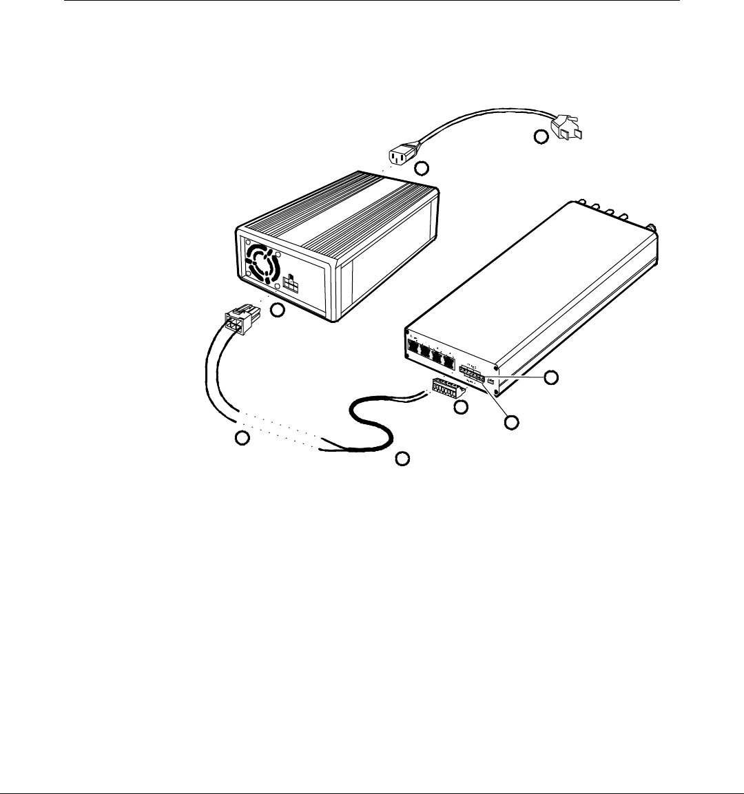
3-22 Chapter 3: Installing the Hardware Infrastructure
2. Splice the power cable wires to the pigtail supplied with the power
supply (black to black and red to white) and then install the
provided crimp connectors over the splices.
18878
5
Red
White
Black
Black
2
1
3
White
Black
Note: Colors shown are for recommended Belden
cables. Your wire colors may be different.
7
8
4
6
3. Plug the connector into the power supply.
4. On the CBS, unplug the power connector.
5. Install the power cable wires into the connector (white into pin 1, 3,
5 or 7 [24 V] and black into pin 2, 4, 6 or 8 [Ground]). Use pins in
pairs: 1-2, 3-4, 5-6, 7-8 for each power cable connection at the CBS.
6. Plug the connector back into the CBS.
7. Insert the AC power cable into the power supply's AC receptacle.
8. Connect the AC plug to the AC power source.
Caution: To prevent damage to the transmitter, the transmit antenna
must be connected to the CBS before applying power to the CBS.

Chapter 3: Installing the Hardware Infrastructure 3-23
CBS Antennas Two types of antennas are available for the CBS:
• Transmit
• Receive
The transmit and receive antennas look similar, but have the following
differences:
• The transmit antenna has a screw-on reverse polarity SMA
connector and uses cable 1424-C424-0018 to connect to the CBS. The
other end of this cable has a reverse polarity TNC connector.
• The receive antenna has a BNC connector and uses cable
1424-C057-0180 to connect to the CBS. This cable has two BNC
connectors.
Note: With 100 mW CBSs, a 15 m (49 ft.) receive antenna cable
1416-C520-0150 must be used instead of the usual 18 m (59 ft.)
receive antenna cable.
Consider the following when installing antennas:
• Install the antennas at the same time you are installing the CBSs.
• On a dropped ceiling, mount the antennas from the T-bars. In an
open ceiling, hang the antennas from the roof trusses.
• When mounting the antenna, face the front of the antenna (the side
opposite the cable connector) towards the ESLs, with as few
obstructions between it and the ESLs as possible.

3-24 Chapter 3: Installing the Hardware Infrastructure
Installing CBS Antennas
The transmit antenna and receive antenna kits include the same
mounting hardware. The installation procedures for the transmit and
receive antennas are the same.
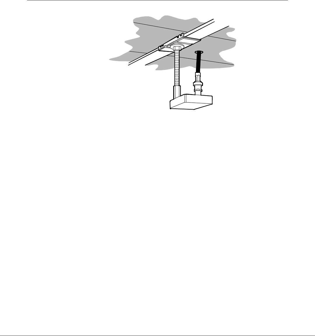
Mounting an Antenna on a T-bar
Note: Maintain a minimum distance of 9.2 m (30 ft.) between a
CBS's transmit and receive antennas.
To install an antenna on a dropped ceiling's T-bar:
1. At the desired location, install a T-bar hanger on the T-bar.
2. Screw the antenna onto the T-bar hanger.
3. Route the antenna cable through a 13 mm (1/2 in.) hole in the
ceiling tile or route it between the T-bar and the edge of the ceiling
tile.
Note: Do not allow debris from the ceiling tile to fall into the antenna
connector.
4. Install the cable onto the antenna connector.
5. Connect the other end of the antenna cable to the CBS.
6. Use cable ties to secure the antenna cable.
Chapter 3: Installing the Hardware Infrastructure 3-25
17203
3-26 Chapter 3: Installing the Hardware Infrastructure
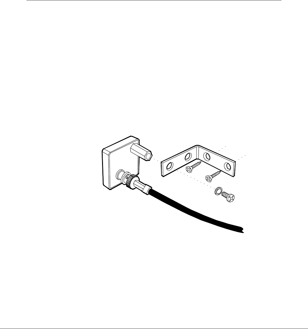
Securing an Antenna to a Wall
Note: Maintain a minimum distance of 9.2 m (30 ft.) between a
CBS's transmit and receive antennas.
To install an antenna on a wall (or other flat object):
1. Place the lock washer on the bolt, put the bolt through the
appropriate hole in the bracket and screw the bolt into the antenna.
2. Screw the bracket into the wall.
3. Connect the antenna cable to the antenna.
4. Connect the antenna cable to the CBS.
5. Use cable ties to secure the antenna cable to the structure.
17204

Chapter 3: Installing the Hardware Infrastructure 3-27
Hanging an Antenna from a Roof Truss
Note: Maintain a minimum distance of 9.2 m (30 ft.) between a
CBS's transmit and receive antennas.
To hang an antenna from a roof truss (or other object) refer to the
illustration on the following page and these instructions:
1. Screw the threaded rod into the antenna.
2. Connect the antenna cable to the antenna.
3. Secure the antenna cable to the threaded rod using three equally
spaced cable ties.
4. In the desired location, hold the antenna cable against a roof truss
and lower the antenna to the desired height.
5. Use a cable tie to hang the antenna cable from the roof truss.
Caution: Antenna cables must be secured to a roof truss as shown in
the following illustration. Do not allow an antenna to hang from a
CBS's connector as the connector cannot withstand the weight of the
threaded rod, cable, and antenna.
6. Connect the antenna cable to the CBS.
7. Use cable ties to secure the antenna cable.
Caution: This device is required to comply with FCC RF exposure
requirements for mobile transmitting devices. A separation of 20 cm (8
inches) or more must be maintained between the antenna and all
persons during device operation to satisfy RF exposure compliance.
!

3-28 Chapter 3: Installing the Hardware Infrastructure
17202

Chapter 3: Installing the Hardware Infrastructure 3-29
CBS Hardware Configuration
After all RF infrastructure components have been installed and the
Ethernet cabling and power supply cabling has been circuit tested for
continuity, the system can be powered-up to establish the connection
between an Ethernet network and the DecisioNet CBS units.
Configure the DHCP Service
Obtain the MAC address from each CBS product label.
Use one of the following to obtain IP addresses for the CBS Units.
• Dynamic or automatic IP allocation where there exists an automatic
DNS link.
• Manual IP allocation is there is no automatic DNS link. For these
stores, a block of addresses are assigned to the site. Select a unique
IP address from the site block to identify each CBS.
Manual Allocation on a Windows NT Server
1. Start the system and Log in as Administrator.
2. Click the Start icon at the bottom left of the screen.
3. Select Programs > Administrative Tools (Common) > DHCP
Manager
The DHCP Manager (Local) screen displays.
3-30 Chapter 3: Installing the Hardware Infrastructure
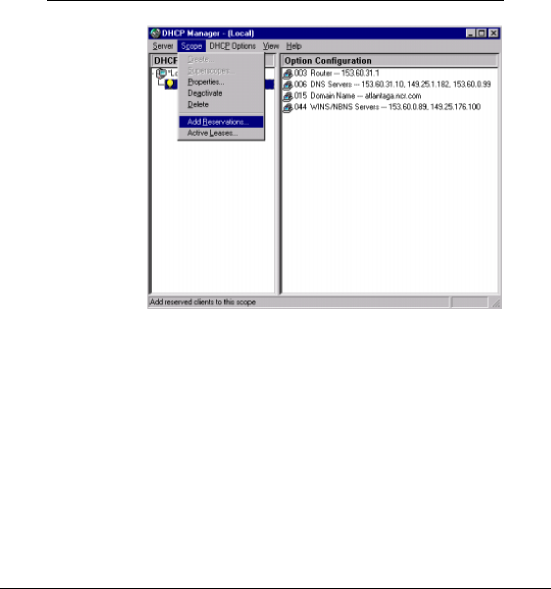
4. Highlight the Server IP address and select Scope > Add
Reservations.
The Add Reserved Clients dialog displays.
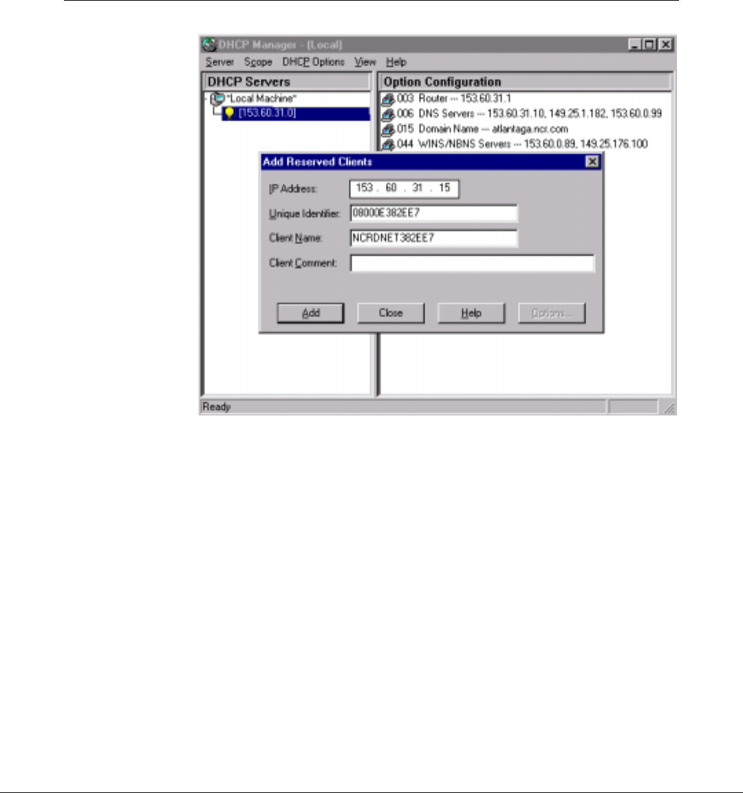
Chapter 3: Installing the Hardware Infrastructure 3-31
5. Enter the next available IP Address in the IP Address entry box.
6. Enter the MAC address from the CBS serial number label in the
Unique Identifier field
7. Enter the DecisioNet Host Name in the Client Name field.
8. Click the Add button.
9. Repeat steps 5 - 8 for each installed CBS.
10. When finished with the last CBS, click the Close button.
11. On the DHCP Manager screen, highlight the Server IP address and
select Scope > Active Leases.
The Active Leases dialog displays showing IP address reserved for
your site.
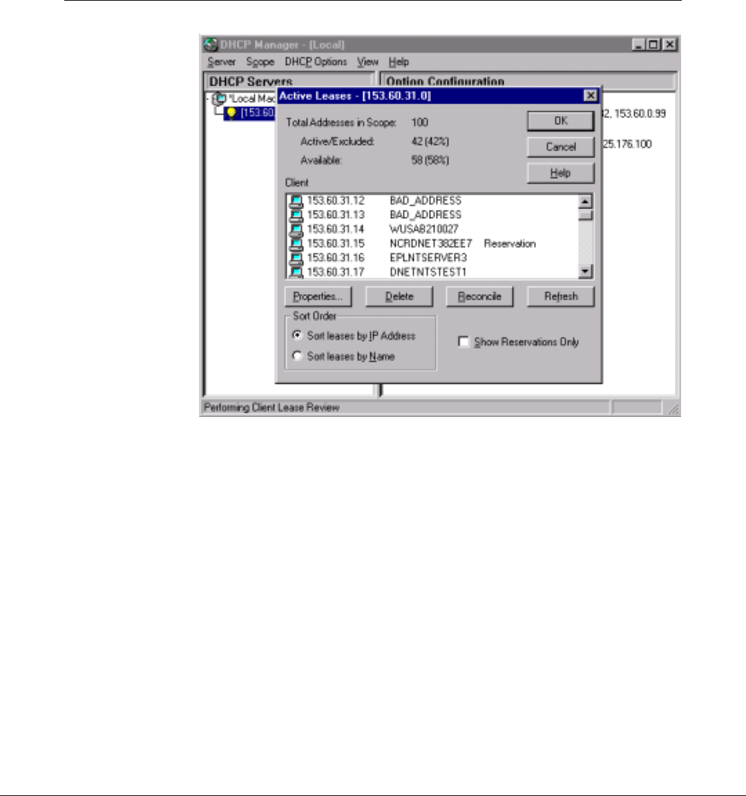
3-32 Chapter 3: Installing the Hardware Infrastructure
12. Click the OK button.
13. Enter these IP addresses or host names in the DecisioNet CBS
Configuration file. Refer to the “Setting the CBS IP Address”
section of Chapter 6, Configuring the DecisioNet System Environment.
Verify Communication Links
Use the following procedures to verify your communication links.
1. Power-up each CBS.
2. Verify that each CBS link status LED is lit.
3. Use the Ping utility to verify connectivity.
4. Use Notepad and view the hosts file in the
\WINNT\system32\drivers\etc\ directory to determine if all
the CBS IP Addresses and host names are listed in the file.

Chapter 3: Installing the Hardware Infrastructure 3-33
Sample HOSTS file:
# Copyright (c) 1993-1995 Microsoft Corp.
#
# This is a sample HOSTS file used by Microsoft TCP/IP for Windows NT.
#
# This file contains the mappings of IP addresses to host names. Each
# entry should be kept on an individual line. The IP address should
# be placed in the first column followed by the corresponding host name.
# The IP address and the host name should be separated by at least one
# space.
#
# Additionally, comments (such as these) may be inserted on individual
# lines or following the machine name denoted by a '#' symbol.
#
# For example:
#
# 102.54.94.97 rhino.acme.com # source server
# 38.25.63.10 x.acme.com # x client host
127.0.0.1 localhost
172.164.48.3 SERVER
172.164.48.10 NCRDNETXXXXXX