NCR RSD Atlanta 7730GAI Electronic Pricing Transmitter User Manual Manual Chapter 3
NCR Corporation, RSD - Atlanta Electronic Pricing Transmitter Manual Chapter 3
UserManual.wiki
>
NCR RSD Atlanta
>
7730GAI User Manual
>
Manual Chapter 3
Contents
1.
Manual Chapter 1
2.
Manual Chapter 2
3.
Manual Chapter 3
4.
Manual Chapter 4
5.
Manual Chapter 5
6.
Manual Chapter 6
7.
Manual Chapter 7
8.
Manual Chapter 8
9.
Manual Cover
10.
Manual Front
11.
Manual Glossary
12.
Manual Index
13.
Users Manual Appendix A
14.
Users Manual Appendix B
Manual Chapter 3
Navigation menu
Upload a User Manual
Namespaces
Wiki Guide
HTML
PDF
Info
Views
User Manual
Discussion / Help
Navigation
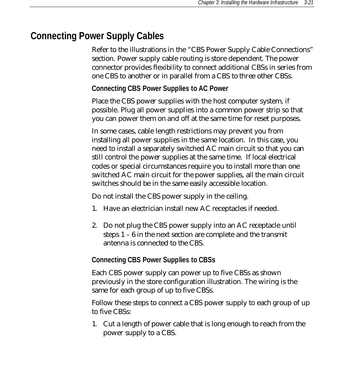
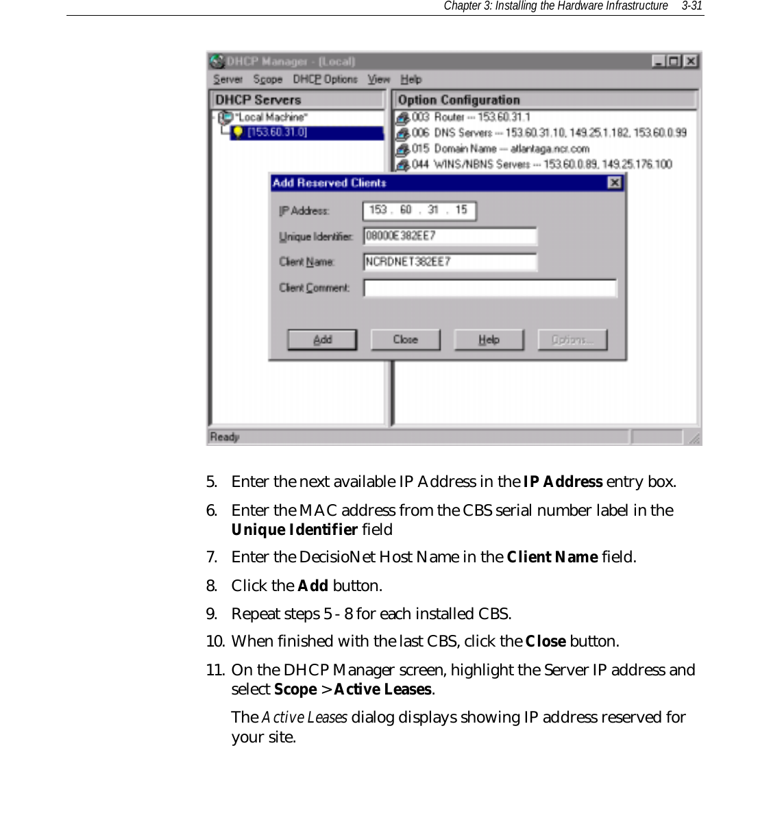
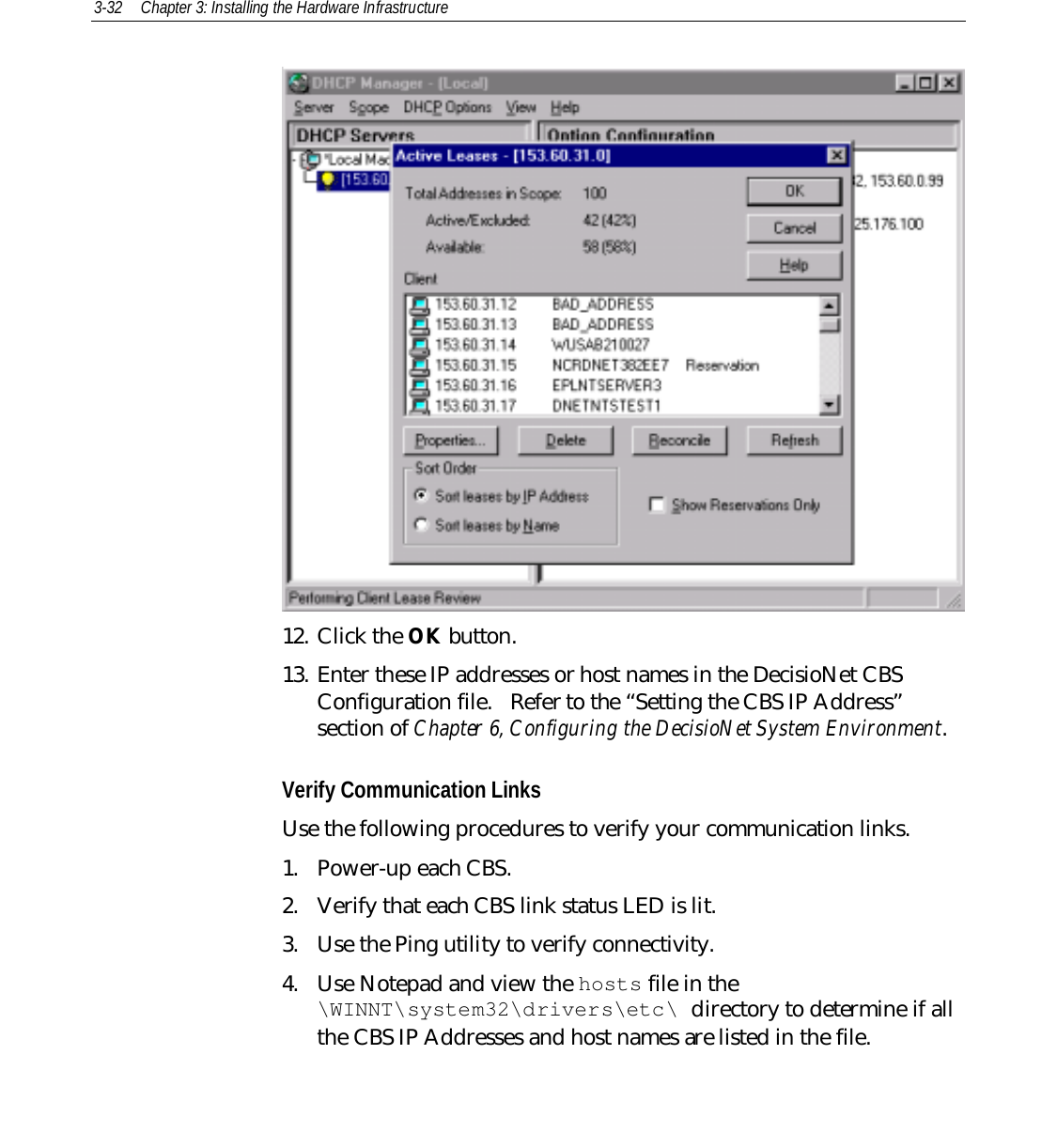
![3-22 Chapter 3: Installing the Hardware Infrastructure2. Splice the power cable wires to the pigtail supplied with the powersupply (black to black and red to white) and then install theprovided crimp connectors over the splices.188785RedWhiteBlackBlack213WhiteBlackNote: Colors shown are for recommended Belden cables. Your wire colors may be different.78463. Plug the connector into the power supply.4. On the CBS, unplug the power connector.5. Install the power cable wires into the connector (white into pin 1, 3,5 or 7 [24 V] and black into pin 2, 4, 6 or 8 [Ground]). Use pins inpairs: 1-2, 3-4, 5-6, 7-8 for each power cable connection at the CBS.6. Plug the connector back into the CBS.7. Insert the AC power cable into the power supply's AC receptacle.8. Connect the AC plug to the AC power source.Caution: To prevent damage to the transmitter, the transmit antennamust be connected to the CBS before applying power to the CBS.](https://usermanual.wiki/NCR-RSD-Atlanta/7730GAI.Manual-Chapter-3/User-Guide-144931-Page-22.png)