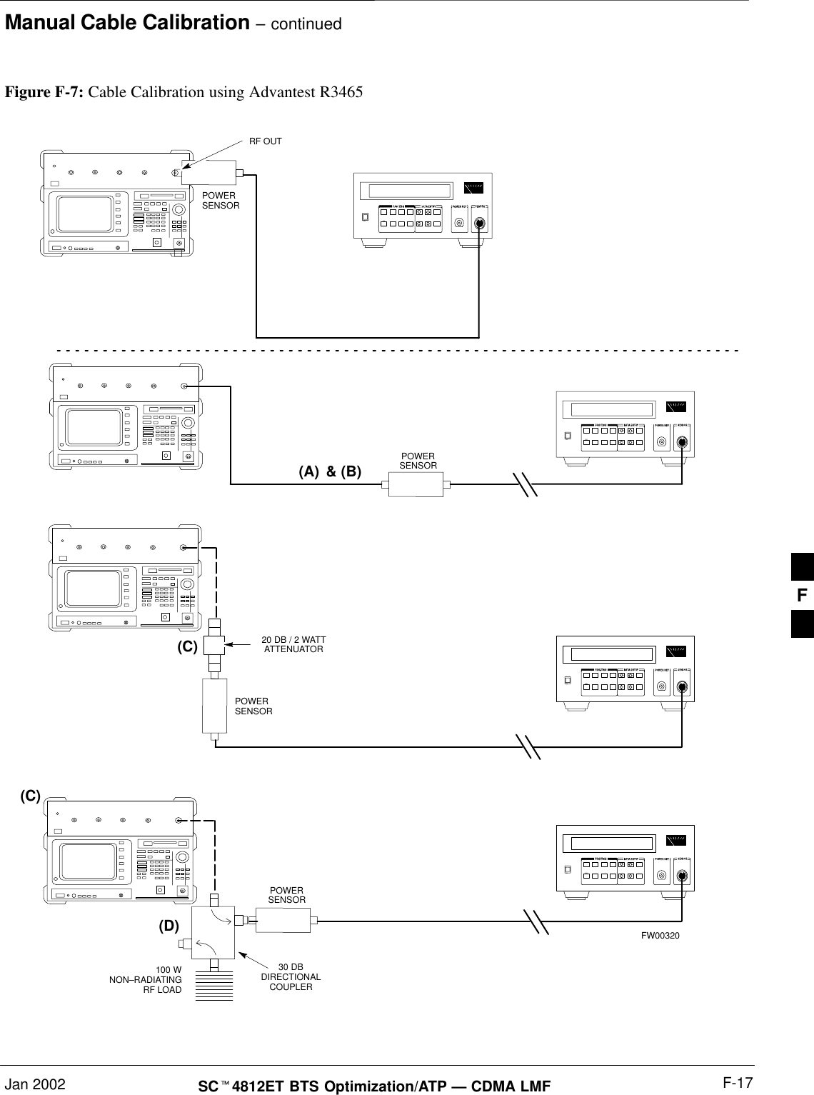
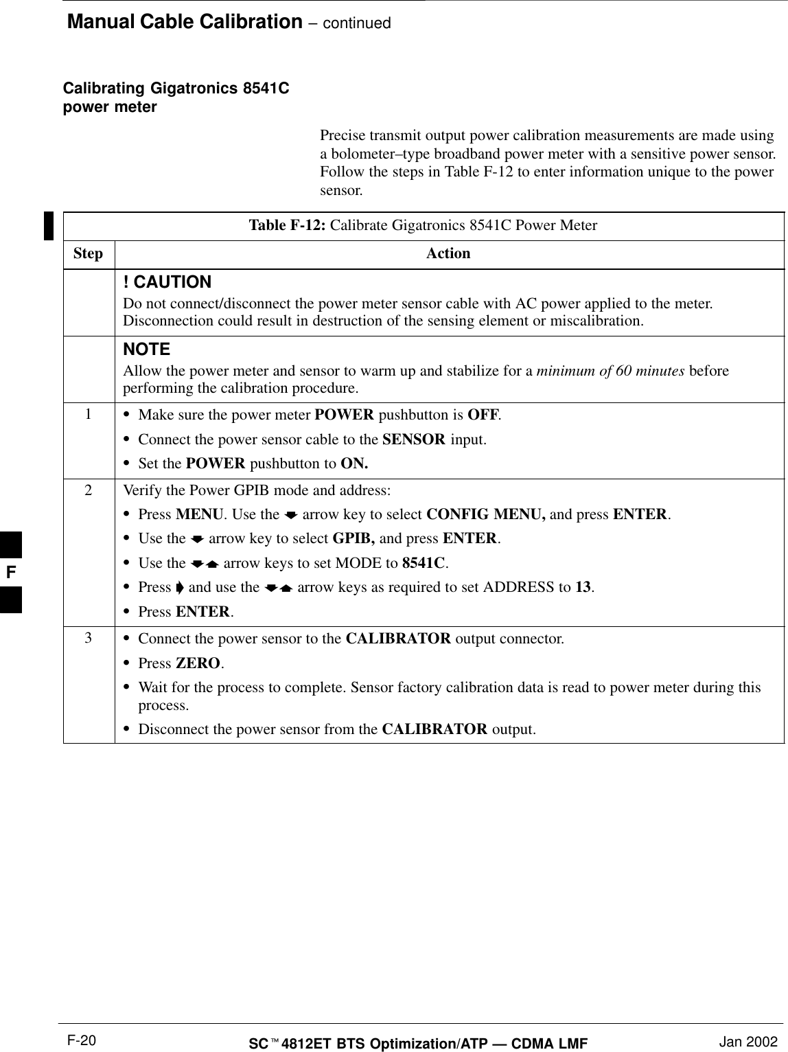
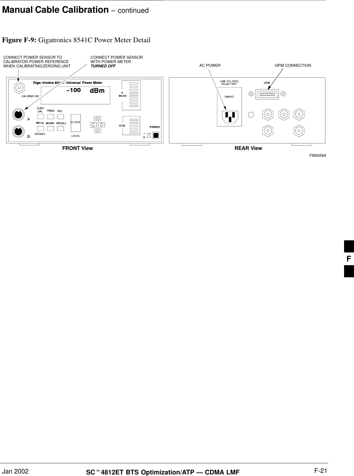
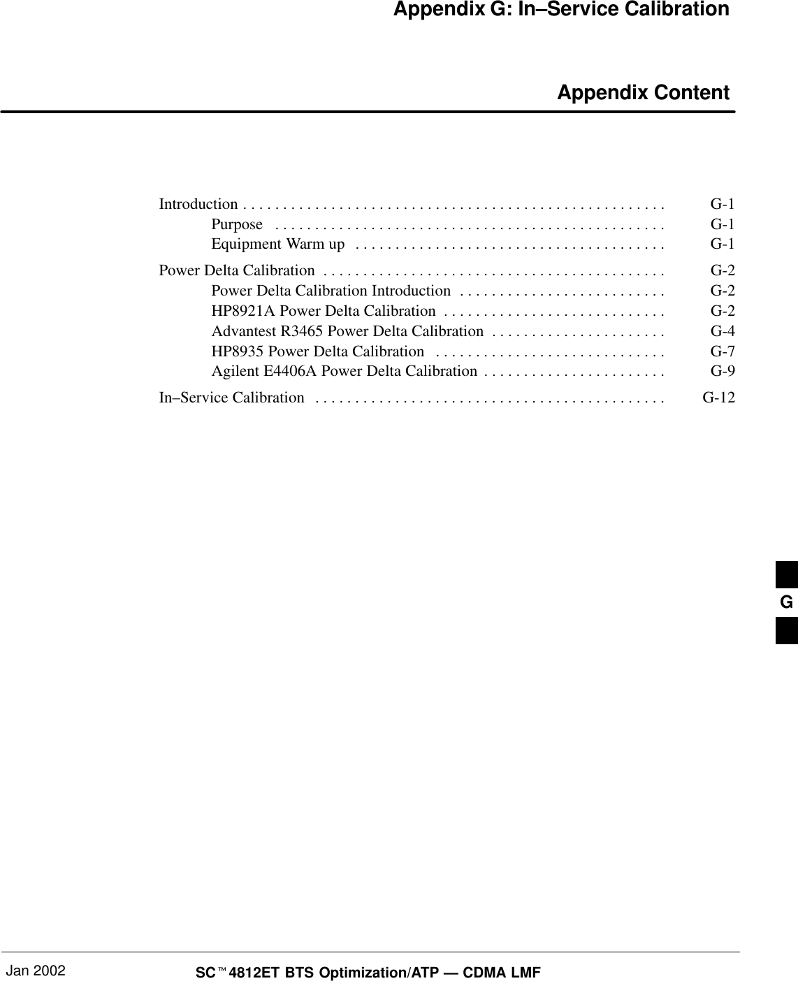
Nokia Solutions and Networks T5CT1 Cellular CDMA base station User Manual IHET5CT1 GLI2 Manual 5 of 6

Nokia Solutions and Networks Cellular CDMA base station IHET5CT1 GLI2 Manual 5 of 6

IHET5CT1 GLI2 Manual 5 of 6

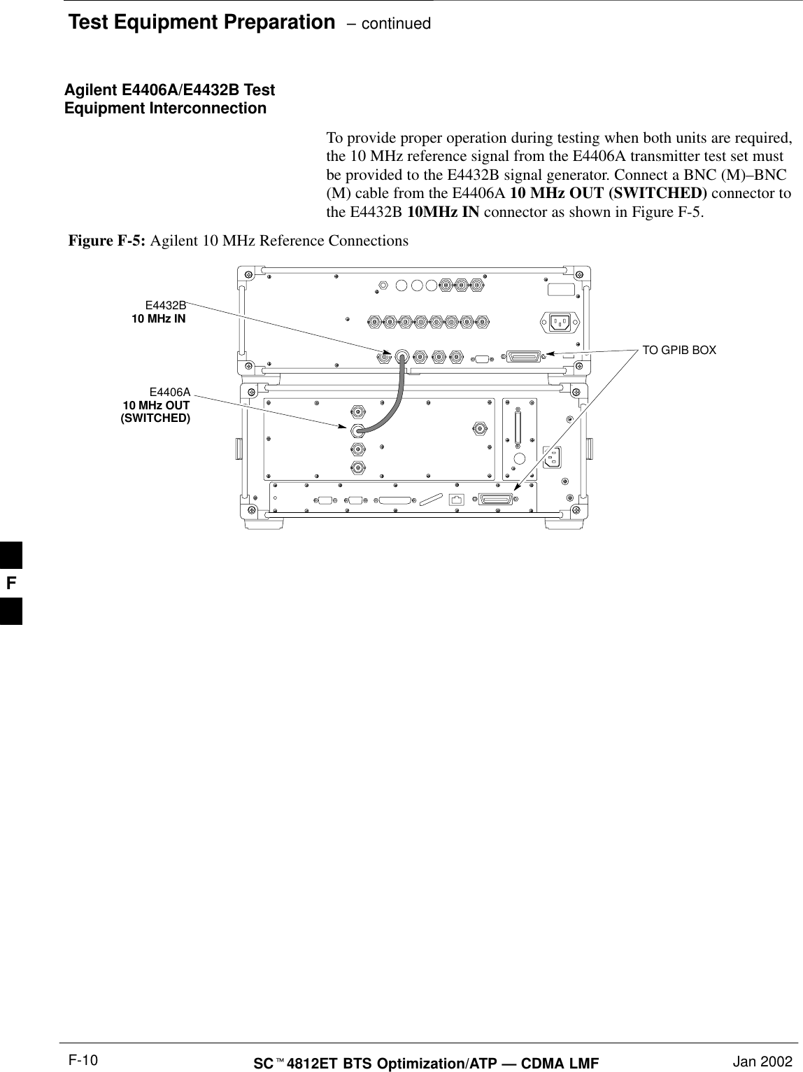
Test Equipment Preparation  – continuedSCt4812ET BTS Optimization/ATP — CDMA LMF Jan 2002F-10Agilent E4406A/E4432B TestEquipment InterconnectionTo provide proper operation during testing when both units are required,the 10 MHz reference signal from the E4406A transmitter test set mustbe provided to the E4432B signal generator. Connect a BNC (M)–BNC(M) cable from the E4406A 10 MHz OUT (SWITCHED) connector tothe E4432B 10MHz IN connector as shown in Figure F-5.Figure F-5: Agilent 10 MHz Reference ConnectionsE4406A10 MHz OUT(SWITCHED)E4432B10 MHz INTO GPIB BOXF
Manual Cable CalibrationJan 2002 F-11SCt4812ET BTS Optimization/ATP — CDMA LMFCalibrating Test Cable Setupusing HP PCS Interface (HP83236)Table F-9 covers the procedure to calibrate the test equipment using the HP8921 Cellular Communications Analyzer equipped with theHP83236 PCS Interface.This calibration method must be executed with great care.Some losses are measured close to the minimum limit ofthe power meter sensor (–30 dBm).NOTEPrerequisitesEnsure the following prerequisites have been met before proceeding:STest equipment to be calibrated has been connected correctly for cablecalibration.STest equipment has been selected and calibrated.Table F-9: Calibrating Test Cable Setup (using the HP PCS Interface)Step ActionNOTEVerify that GPIB controller is turned off.1Insert HP83236 Manual Control System card into memory card slot.2Press the Preset pushbutton.3 Under Screen Controls, press the TESTS pushbutton to display the TESTS (Main Menu) screen.4Position the cursor at Select Procedure Location and select it. In the Choices selection box, selectCARD.5Position the cursor at Select Procedure Filename and select it. In the Choices selection box, selectMANUAL.6Position the cursor at RUN TEST and select it. HP must be in Control Mode Select YES.7If using HP 83236A:Set channel number=<chan#>:–Position cursor at ChannelNumber and select it.–Enter the chan# using the numerickeypad; press [Enter] and thescreen will go blank.–When the screen reappears, thechan# will be displayed on thechannel number line.If using HP 83236B:Set channel frequency:–Position cursor at Frequency Band and press Enter.–Select User Defined Frequency.–Go Back to Previous Menu.–Position the cursor to 83236 generator frequency andenter actual RX frequency.–Position the cursor to 83236 analyzer frequency andenter actual TX frequency.. . . continued on next pageF
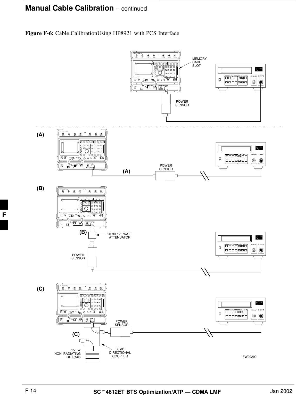
Manual Cable Calibration – continuedSCt4812ET BTS Optimization/ATP — CDMA LMF Jan 2002F-12Table F-9: Calibrating Test Cable Setup (using the HP PCS Interface)Step Action8Set RF Generator level:–Position the cursor at RF Generator Level and select it.–Enter –10 using the numeric keypad; press [Enter] and the screen will go blank.–When the screen reappears, the value –10 dBm will be displayed on the RF Generator Level line.9Set the user fixed Attenuation Setting to 0 dBm:–Position cursor at Analyzer Attenuation and select it–Position cursor at User Fixed Atten Settings and select it.–Enter 0 (zero) using the numeric keypad and press [Enter].10 Select Back to Previous Menu.11 Record the HP83236 Generator Frequency Level:Record the HP83236B Generator Frequency Level:–Position cursor at Show Frequency and Level Details and select it.–Under HP83236 Frequencies and Levels, record the Generator Level.–Under HP83236B Frequencies and Levels, record the Generator Frequency Level (1850 – 1910MHz).–Position cursor at Prev Menu and select it.12 Click on Pause for Manual Measurement.13 Connect the power sensor directly to the RF OUT ONLY port of the PCS Interface.14 On the HP8921A, under To Screen, select CDMA GEN.15 Move the cursor to the Amplitude field and click on the Amplitude value.16 Increase the Amplitude value until the power meter reads 0 dBm ±0.2 dB.NOTEThe Amplitude value can be increased coarsely until 0 dBM is reached; then fine tune the amplitudeby adjusting the Increment Set to 0.1 dBm and targeting in on 0 dBm.17 Disconnect the power sensor from the RF OUT ONLY port of the PCS Interface.* IMPORTANTThe Power Meter sensor’s lower limit is –30 dBm. Thus, only components having losses ≤30 dBshould be measured using this method. For further accuracy, always re-zero the power meterbefore connecting the power sensor to the component being calibrated. After connecting thepower sensor to the component, record the calibrated loss immediately.18 Disconnect all components in the test setup and calibrate each one separately by connecting eachcomponent, one-at-a-time, between the RF OUT ONLY PORT and the power sensor. Record thecalibrated loss value displayed on the power meter.SExample: (A) Test Cable(s) = –1.4 dB(B) 20 dB Attenuator  = –20.1 dB(B) Directional Coupler = –29.8 dB. . . continued on next pageF
Manual Cable Calibration – continuedJan 2002 F-13SCt4812ET BTS Optimization/ATP — CDMA LMFTable F-9: Calibrating Test Cable Setup (using the HP PCS Interface)Step Action19 After all components are calibrated, reassemble all components together and calculate the total testsetup loss by adding up all the individual losses:SExample: Total test setup loss = –1.4 –29.8 –20.1 = –51.3 dB.This calculated value will be used in the next series of tests.20 Under Screen Controls press the TESTS button to display the TESTS (Main Menu) screen.21 Select Continue (K2).22 Select RF Generator Level and set to –119 dBm.23 Click on Pause for Manual Measurement.24 Verify the HP8921A Communication Analyzer/83203A CDMA interface setup is as follows (fieldsnot indicated remain at default):SVerify the GPIB (HP–IB) address:–under To Screen, select More–select IO CONFIG–Set HP–IB Adrs to 18–set Mode to Talk&LstnSVerify the HP8921A is displaying frequency (instead of RF channel)–Press the blue [SHIFT] button, then press the Screen Control [DUPLEX] button; this switches tothe CONFIG (CONFIGURE) screen.–Use the cursor control to set RF Display to Freq25 Refer toChapter 3 for assistance in setting the cable loss values into the LMF. F
Manual Cable Calibration – continuedSCt4812ET BTS Optimization/ATP — CDMA LMF Jan 2002F-14(A)(C)POWERSENSOR(A)POWERSENSOR(C)30 dBDIRECTIONALCOUPLER150 WNON–RADIATINGRF LOADPOWERSENSOR(B)POWERSENSOR(B)MEMORYCARDSLOT20 dB / 20 WATTATTENUATORFW00292Figure F-6: Cable CalibrationUsing HP8921 with PCS InterfaceF
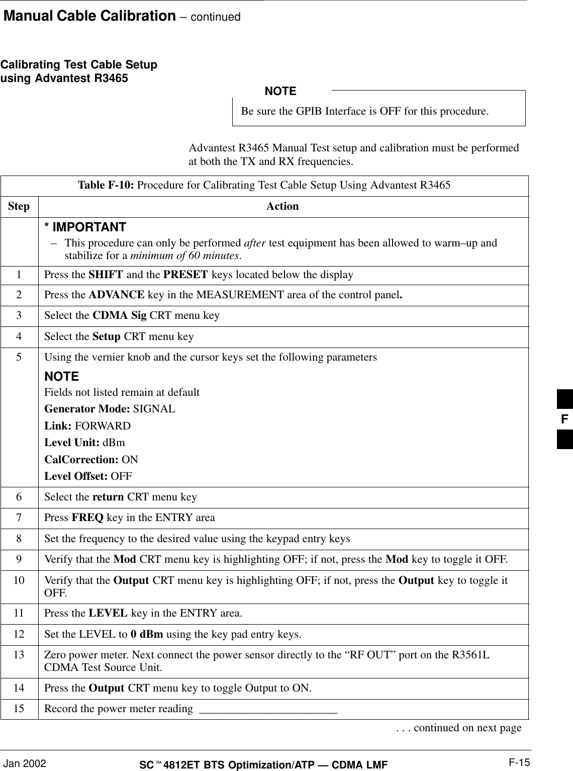
Manual Cable Calibration – continuedJan 2002 F-15SCt4812ET BTS Optimization/ATP — CDMA LMFCalibrating Test Cable Setupusing Advantest R3465Be sure the GPIB Interface is OFF for this procedure.NOTEAdvantest R3465 Manual Test setup and calibration must be performedat both the TX and RX frequencies.Table F-10: Procedure for Calibrating Test Cable Setup Using Advantest R3465Step Action* IMPORTANT–This procedure can only be performed after test equipment has been allowed to warm–up andstabilize for a minimum of 60 minutes.1Press the SHIFT and the PRESET keys located below the display2Press the ADVANCE key in the MEASUREMENT area of the control panel.3Select the CDMA Sig CRT menu key4Select the Setup CRT menu key5Using the vernier knob and the cursor keys set the following parametersNOTEFields not listed remain at defaultGenerator Mode: SIGNALLink: FORWARDLevel Unit: dBmCalCorrection: ONLevel Offset: OFF6Select the return CRT menu key7 Press FREQ key in the ENTRY area8Set the frequency to the desired value using the keypad entry keys9Verify that the Mod CRT menu key is highlighting OFF; if not, press the Mod key to toggle it OFF.10 Verify that the Output CRT menu key is highlighting OFF; if not, press the Output key to toggle itOFF.11 Press the LEVEL key in the ENTRY area.12 Set the LEVEL to 0 dBm using the key pad entry keys.13 Zero power meter. Next connect the power sensor directly to the “RF OUT” port on the R3561LCDMA Test Source Unit.14 Press the Output CRT menu key to toggle Output to ON.15 Record the power meter reading  ________________________. . . continued on next pageF
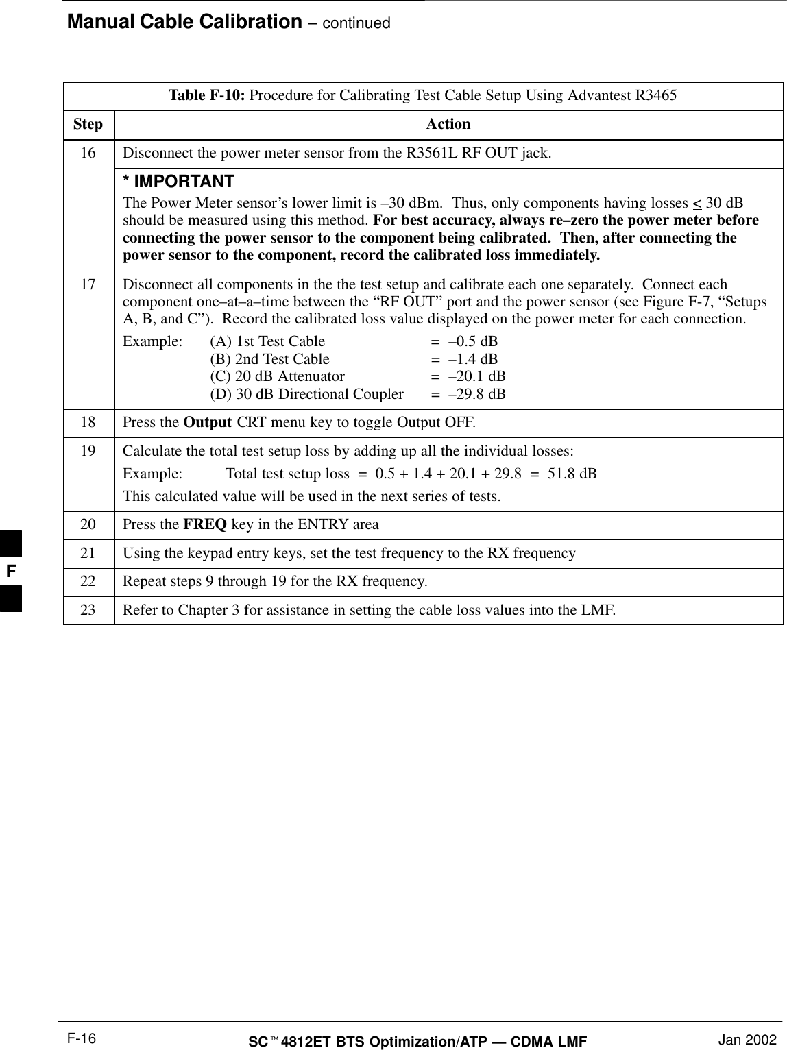
Manual Cable Calibration – continuedSCt4812ET BTS Optimization/ATP — CDMA LMF Jan 2002F-16Table F-10: Procedure for Calibrating Test Cable Setup Using Advantest R3465Step Action16 Disconnect the power meter sensor from the R3561L RF OUT jack.* IMPORTANTThe Power Meter sensor’s lower limit is –30 dBm.  Thus, only components having losses < 30 dBshould be measured using this method. For best accuracy, always re–zero the power meter beforeconnecting the power sensor to the component being calibrated.  Then, after connecting thepower sensor to the component, record the calibrated loss immediately.17 Disconnect all components in the the test setup and calibrate each one separately.  Connect eachcomponent one–at–a–time between the “RF OUT” port and the power sensor (see Figure F-7, “SetupsA, B, and C”).  Record the calibrated loss value displayed on the power meter for each connection.Example:  (A) 1st Test Cable =  –0.5 dB(B) 2nd Test Cable  =  –1.4 dB(C) 20 dB Attenuator  =  –20.1 dB(D) 30 dB Directional Coupler  =  –29.8 dB18 Press the Output CRT menu key to toggle Output OFF.19 Calculate the total test setup loss by adding up all the individual losses:Example:  Total test setup loss  =  0.5 + 1.4 + 20.1 + 29.8  =  51.8 dBThis calculated value will be used in the next series of tests.20 Press the FREQ key in the ENTRY area21 Using the keypad entry keys, set the test frequency to the RX frequency22 Repeat steps 9 through 19 for the RX frequency.23 Refer to Chapter 3 for assistance in setting the cable loss values into the LMF. F
Manual Cable Calibration – continuedJan 2002 F-17SCt4812ET BTS Optimization/ATP — CDMA LMFPOWERSENSOR20 DB / 2 WATTATTENUATOR(A)(C)POWERSENSOR(D)30 DBDIRECTIONALCOUPLER(C)100 WNON–RADIATINGRF LOADPOWERSENSORRF OUTPOWERSENSOR& (B)FW00320Figure F-7: Cable Calibration using Advantest R3465F
Manual Cable Calibration – continuedSCt4812ET BTS Optimization/ATP — CDMA LMF Jan 2002F-18Calibrating HP 437 PowerMeterPrecise transmit output power calibration measurements are made usinga bolometer–type broadband power meter with a sensitive power sensor.Follow the steps outlined in Table F-11 to enter information unique tothe power sensor before calibrating the test setup. Refer to Figure F-8 asrequired.This procedure must be done in conjunction with theautomated calibration to enter power sensor specificcalibration values.IMPORTANT*CONNECT POWERSENSOR WITH POWERMETER TURNED OFFCONNECT POWER SENSORTO POWER REFERENCEWHEN CALIBRATING UNIT.POWER REFERENCE ISENABLED USING THE SHIFT 'KEYSSHIFT (BLUE) PUSHBUTTON –ACCESSES FUNCTION ANDDATA ENTRY KEYS IDENTIFIEDWITH LIGHT BLUE TEXT ONTHE FRONT PANEL ABOVETHE BUTTONSFW00308Figure F-8: Power Meter DetailTable F-11: Power Meter Calibration ProcedureStep Action! CAUTIONDo not connect/disconnect the power meter sensor cable with ac power applied to the meter.Disconnection could result in destruction of the sensing element or mis–calibration.1–Make sure the power meter AC LINE pushbutton is OFF.–Connect the power sensor cable to the SENSOR input.2Set the AC LINE pushbutton to ON.NOTEThe calibration should be performed only after the power meter and sensor have been allowed towarm–up and stabilize for a minimum of 60 minutes.3Perform the following to set or verify the GPIB address:–To enter the SPECIAL data entry function, press [SHIFT] then [PRESET].–Use the [y] or [b] button to select HP–IB ADRS; then press [ENTER].–Use the [y] or [b] button to select HP–IB ADRS 13; then press [ENTER].–To EXIT the SPECIAL data entry function press [SHIFT] then [ENTER].. . . continued on next pageF
Manual Cable Calibration – continuedJan 2002 F-19SCt4812ET BTS Optimization/ATP — CDMA LMFTable F-11: Power Meter Calibration ProcedureStep Action4Perform the following to set or verify the correct power sensor model:–Press [SHIFT]  then [a] to select SENSOR.–Identify the power sensor model number from the sensor label.  Use the [y] or [b] button toselect the appropriate model; then press [ENTER].NOTEBe sure the PWR REF (power reference) output is OFF (observe that the triangular indicator is NOTdisplayed as shown in Step 7). If on, press [SHIFT] then ['] to turn it off.5 Press [ZERO].  Display will show “Zeroing ******.”  Wait for process to complete.6Connect the power sensor to the POWER REF output.7To turn on the PWR REF, perform the following:–Press [SHIFT] then ['].–Verify that the triangular indicator (below) appears in the display above “PWR REF”.8Perform the following to set the REF CF %:–Press ([SHIFT] then [ZERO]) for CAL.–Enter the sensor’s REF CF % from the sensor’s decal using the arrow keys and press [ENTER].(The power meter will display ”CAL *****” for a few seconds.)NOTEIf the REF CAL FACTOR (REF CF) is not shown on the power sensor, assume it to be 100%.9Perform the following to set the CAL FAC %:–Press [SHIFT] then [FREQ] for CAL FAC.–On the sensor’s decal, locate an approximate calibration percentage factor (CF%) at 2 GHz.  Enterthe sensor’s calibration % (CF%) using the arrow keys and press [ENTER].When complete, the power meter will typically display 0.05 dBm. (Any reading between 0.00 and0.10 is normal.)10 To turn off the PWR REF, perform the following:–Press [SHIFT] then ['].–Disconnect the power sensor from the POWER REF output. F
Manual Cable Calibration – continuedSCt4812ET BTS Optimization/ATP — CDMA LMF Jan 2002F-20Calibrating Gigatronics 8541Cpower meterPrecise transmit output power calibration measurements are made usinga bolometer–type broadband power meter with a sensitive power sensor.Follow the steps in Table F-12 to enter information unique to the powersensor.Table F-12: Calibrate Gigatronics 8541C Power MeterStep Action! CAUTIONDo not connect/disconnect the power meter sensor cable with AC power applied to the meter.Disconnection could result in destruction of the sensing element or miscalibration.NOTEAllow the power meter and sensor to warm up and stabilize for a minimum of 60 minutes beforeperforming the calibration procedure.1SMake sure the power meter POWER pushbutton is OFF.SConnect the power sensor cable to the SENSOR input.SSet the POWER pushbutton to ON.2Verify the Power GPIB mode and address:SPress MENU. Use the b arrow key to select CONFIG MENU, and press ENTER.SUse the b arrow key to select GPIB, and press ENTER.SUse the by arrow keys to set MODE to 8541C.SPress ' and use the by arrow keys as required to set ADDRESS to 13.SPress ENTER.3SConnect the power sensor to the CALIBRATOR output connector.SPress ZERO.SWait for the process to complete. Sensor factory calibration data is read to power meter during thisprocess.SDisconnect the power sensor from the CALIBRATOR output.F
Manual Cable Calibration – continuedJan 2002 F-21SCt4812ET BTS Optimization/ATP — CDMA LMFFigure F-9: Gigatronics 8541C Power Meter DetailCONNECT POWER SENSORWITH POWER METERTURNED OFFCONNECT POWER SENSOR TOCALIBRATOR POWER REFERENCEWHEN CALIBRATING/ZEROING UNITFRONT View REAR ViewGPIB CONNECTIONAC POWERFW00564F
Manual Cable Calibration – continuedSCt4812ET BTS Optimization/ATP — CDMA LMF Jan 2002F-22NotesF
Jan 2002 SCt4812ET BTS Optimization/ATP — CDMA LMFAppendix G: In–Service Calibration Appendix ContentIntroduction G-1. . . . . . . . . . . . . . . . . . . . . . . . . . . . . . . . . . . . . . . . . . . . . . . . . . . . . Purpose G-1. . . . . . . . . . . . . . . . . . . . . . . . . . . . . . . . . . . . . . . . . . . . . . . . . Equipment Warm up G-1. . . . . . . . . . . . . . . . . . . . . . . . . . . . . . . . . . . . . . . Power Delta Calibration G-2. . . . . . . . . . . . . . . . . . . . . . . . . . . . . . . . . . . . . . . . . . . Power Delta Calibration Introduction G-2. . . . . . . . . . . . . . . . . . . . . . . . . . HP8921A Power Delta Calibration G-2. . . . . . . . . . . . . . . . . . . . . . . . . . . . Advantest R3465 Power Delta Calibration G-4. . . . . . . . . . . . . . . . . . . . . . HP8935 Power Delta Calibration G-7. . . . . . . . . . . . . . . . . . . . . . . . . . . . . Agilent E4406A Power Delta Calibration G-9. . . . . . . . . . . . . . . . . . . . . . . In–Service Calibration G-12. . . . . . . . . . . . . . . . . . . . . . . . . . . . . . . . . . . . . . . . . . . . G
Table of Contents  – continuedSCt4812ET BTS Optimization/ATP — CDMA LMF Jan 2002NotesG
IntroductionJan 2002 G-1SCt4812ET BTS Optimization/ATP — CDMA LMFPurposeThis procedure is a guide to expanding your system with multiplecarriers while the system remains in service. This procedure also allowsyou to perform on site maintenance (replace defective boards andrecalibrate) while the remainder of the site stays in service.Motorola recommends that you perform this procedure during amaintenance window.This procedure cannot be performed on BTSs with 4–to–1 combiners.The procedure can only be performed on one side of the BTS at onetime. That is, LPAs 1, 2 ,3, 7, 8, 9 (feed antennas 1, 2, 3) can becalibrated while LPAs 6, 7, 8, 10, 11, 12 (feed antennas 4, 5, 6) remainin service and vice versa.Equipment Warm upCalibration of the communications test set (or equivalenttest equipment) must be performed at the site beforecalibrating the overall test set. Calibrate the test equipmentafter it has been allowed to warm-up and stabilize for aminimum of 60 minutes.IMPORTANT*If any piece of test equipment (i.e., test cable, RF adapter)has been replaced, re-calibration must be performed.Failure to do so could introduce measurement errors,causing incorrect measurements and degradation to systemperformance.CAUTIONG
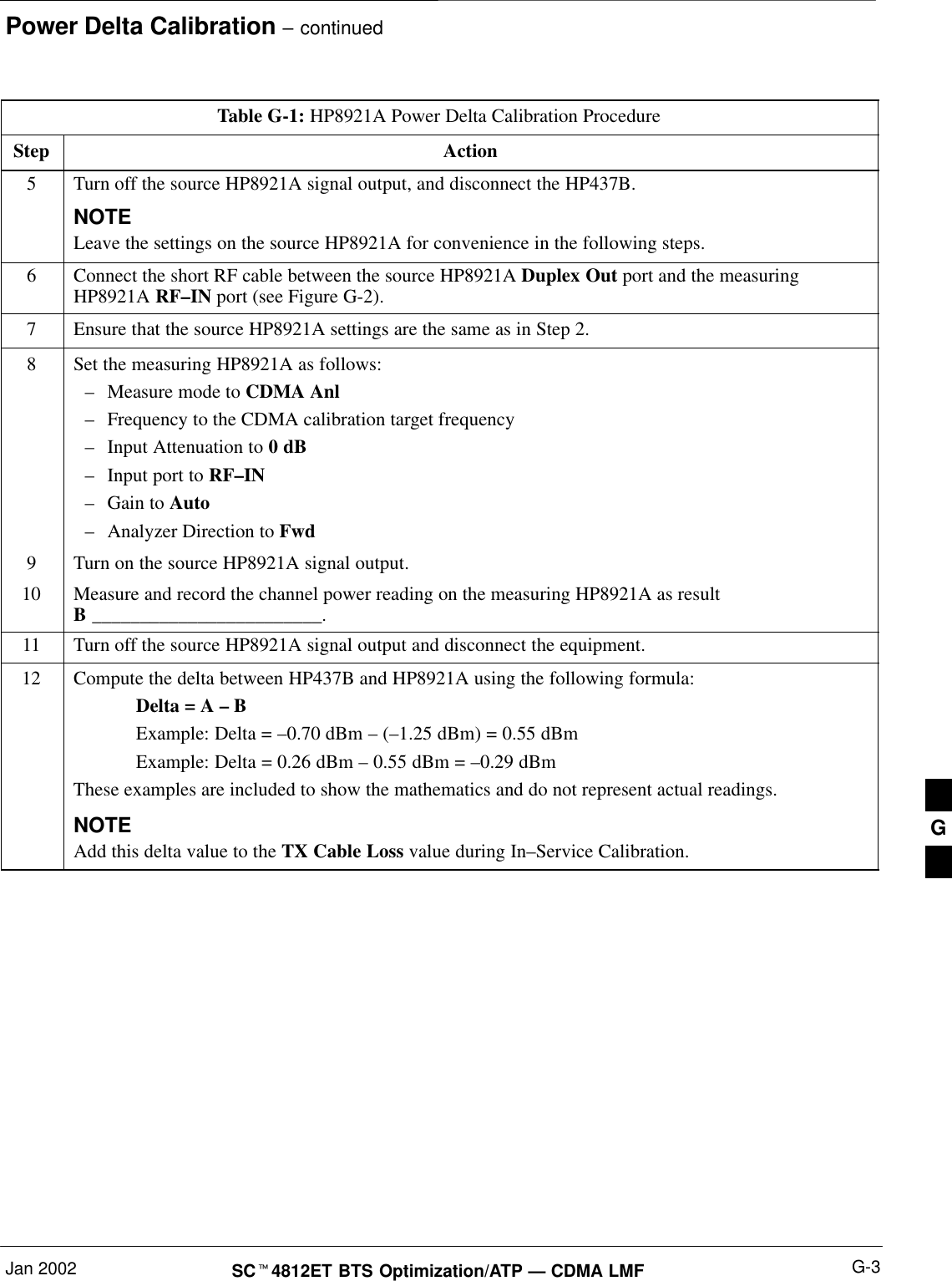
Power Delta CalibrationSCt4812ET BTS Optimization/ATP — CDMA LMF Jan 2002G-2Power Delta CalibrationIntroductionThe In–service calibration procedure has several differences from anormal calibration procedure. One of these is the use of a spectrumanalyzer instead of a power meter to measure power. Power meters arebroadband measurement devices and cannot be used to measure powerduring In–service Calibration since other carriers are operating. Aspectrum analyzer can be used because it measures power at a givenfrequency. However, measuring power using a spectrum analyzer is lessaccurate than using a power meter. Therefore, you must compensate forthe difference (delta) between the power meter and the spectrumanalyzer.HP8921A Power DeltaCalibrationUse the HP8921A Spectrum Analyzer to measure power duringIn–Service Calibration for 800 MHz systems. After the offset value hasbeen calculated, add it to the TX cable loss value.Follow the procedure in Table G-1 to perform the HP8921A Power DeltaCalibration procedure.This procedure requires two HP8921As.NOTETable G-1: HP8921A Power Delta Calibration ProcedureStep Action* IMPORTANTPerform this procedure after test equipment has been allowed to warm–up and stabilize for a minimumof 60 minutes.1Connect a short RF cable between the HP8921A Duplex Out port and the HP437B power sensor (seeFigure G-1).2Set the HP8921A signal source as follows:–Measure mode to CDMA Generator–Frequency to the CDMA Calibration target frequency–CW RF Path to IQ–Output Port to Dupl–Data Source to Random–Amplitude to 0 dBm3Measure and record the power value reading on the HP437B Power Meter.4Record the Power Meter reading as result A ________________________.. . . continued on next pageG
Power Delta Calibration – continuedJan 2002 G-3SCt4812ET BTS Optimization/ATP — CDMA LMFTable G-1: HP8921A Power Delta Calibration ProcedureStep Action5Turn off the source HP8921A signal output, and disconnect the HP437B.NOTELeave the settings on the source HP8921A for convenience in the following steps.6Connect the short RF cable between the source HP8921A Duplex Out port and the measuringHP8921A RF–IN port (see Figure G-2).7Ensure that the source HP8921A settings are the same as in Step 2.8Set the measuring HP8921A as follows:–Measure mode to CDMA Anl–Frequency to the CDMA calibration target frequency–Input Attenuation to 0 dB–Input port to RF–IN–Gain to Auto–Analyzer Direction to Fwd9Turn on the source HP8921A signal output.10 Measure and record the channel power reading on the measuring HP8921A as resultB ________________________.11 Turn off the source HP8921A signal output and disconnect the equipment.12 Compute the delta between HP437B and HP8921A using the following formula:Delta = A – BExample: Delta = –0.70 dBm – (–1.25 dBm) = 0.55 dBmExample: Delta = 0.26 dBm – 0.55 dBm = –0.29 dBmThese examples are included to show the mathematics and do not represent actual readings.NOTEAdd this delta value to the TX Cable Loss value during In–Service Calibration. G
Power Delta Calibration – continuedSCt4812ET BTS Optimization/ATP — CDMA LMF Jan 2002G-4Figure G-1: Delta Calibration Setup – HP8921A to HP437BShort RF CableHP 8921ADUPLEXOUTHP437BPowerSensorSENSORFW00801Figure G-2: Delta Calibration Setup – HP8921A toHP8921A Measurement HP8921A Source HP8921AShort RF CableDUPLEXOUTRFIN/OUTFW00802Advantest R3465 Power DeltaCalibrationFollow the procedure in Table G-2 to perform the Advantest 3465 PowerDelta Calibration procedure.Table G-2: Advantest Power Delta Calibration ProcedureStep Action* IMPORTANTPerform this procedure after test equipment has been allowed to warm–up and stabilize for a minimumof 60 minutes.On the Advantest R3465:1Press the SHIFT and the PRESET keys located below the CRT display.2Press the ADVANCE key in the Measurement area of the control panel.3Press the CDMA Sig CRT menu key.4Press the FREQ key in the Entry area of the control panel.. . . continued on next pageG
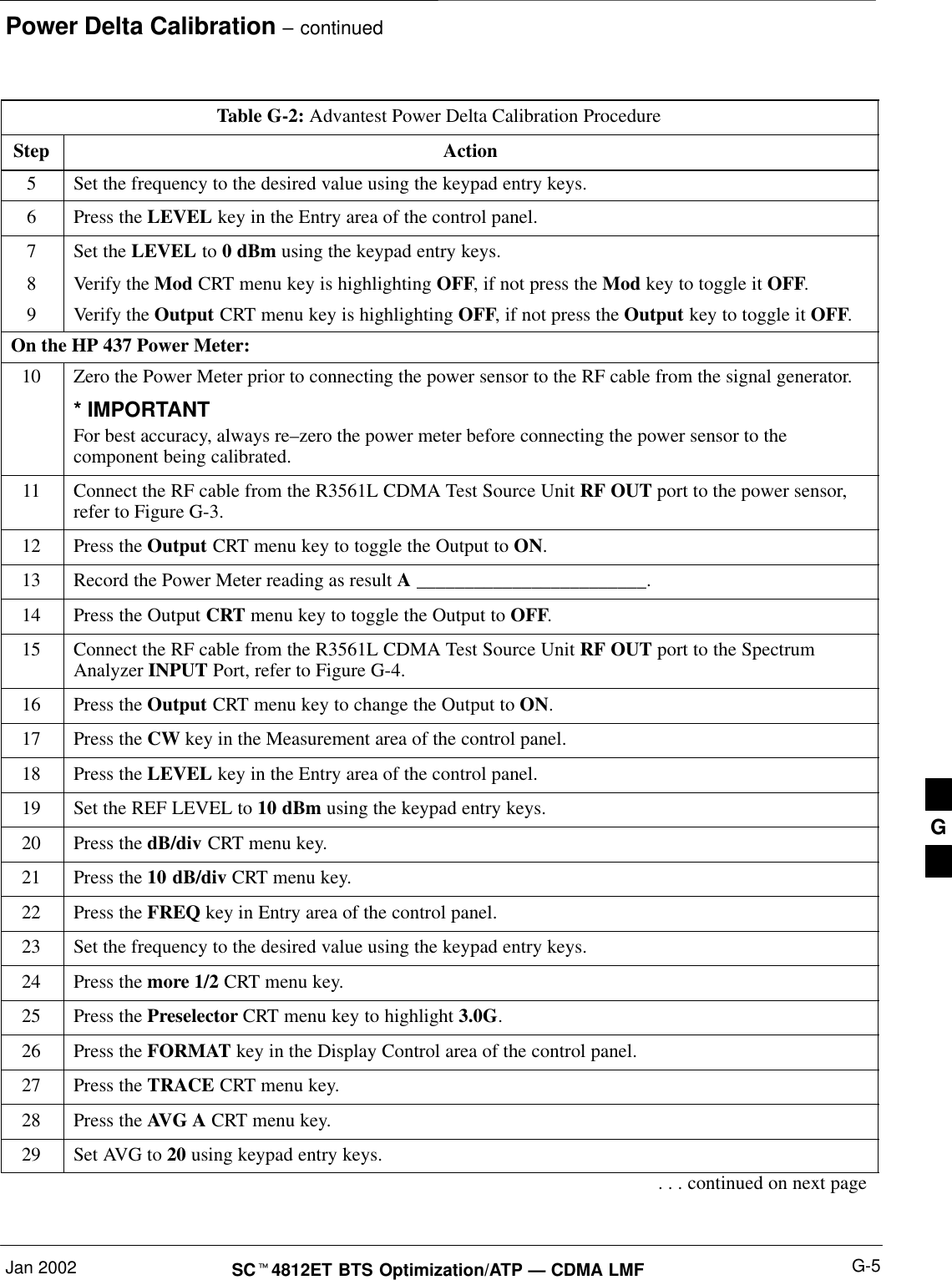
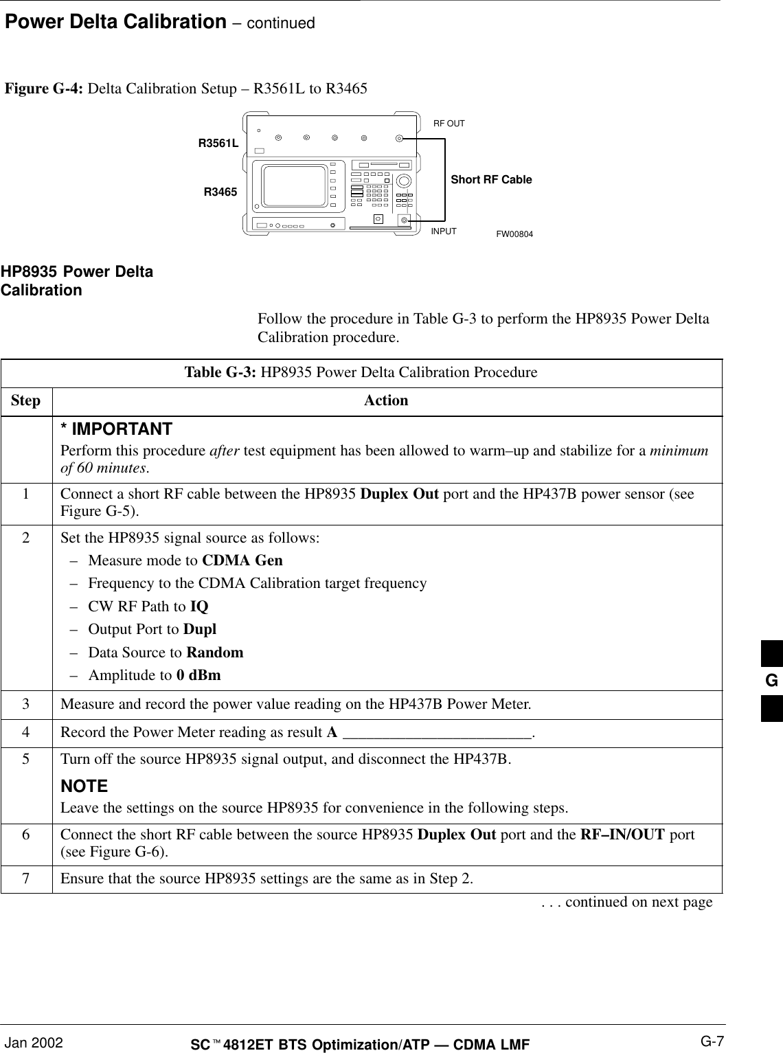
Power Delta Calibration – continuedJan 2002 G-5SCt4812ET BTS Optimization/ATP — CDMA LMFTable G-2: Advantest Power Delta Calibration ProcedureStep Action5Set the frequency to the desired value using the keypad entry keys.6Press the LEVEL key in the Entry area of the control panel.7Set the LEVEL to 0 dBm using the keypad entry keys.8Verify the Mod CRT menu key is highlighting OFF, if not press the Mod key to toggle it OFF.9Verify the Output CRT menu key is highlighting OFF, if not press the Output key to toggle it OFF.On the HP 437 Power Meter:10 Zero the Power Meter prior to connecting the power sensor to the RF cable from the signal generator.* IMPORTANTFor best accuracy, always re–zero the power meter before connecting the power sensor to thecomponent being calibrated.11 Connect the RF cable from the R3561L CDMA Test Source Unit RF OUT port to the power sensor,refer to Figure G-3.12 Press the Output CRT menu key to toggle the Output to ON.13 Record the Power Meter reading as result A ________________________.14 Press the Output CRT menu key to toggle the Output to OFF.15 Connect the RF cable from the R3561L CDMA Test Source Unit RF OUT port to the SpectrumAnalyzer INPUT Port, refer to Figure G-4.16 Press the Output CRT menu key to change the Output to ON.17 Press the CW key in the Measurement area of the control panel.18 Press the LEVEL key in the Entry area of the control panel.19 Set the REF LEVEL to 10 dBm using the keypad entry keys.20 Press the dB/div CRT menu key.21 Press the 10 dB/div CRT menu key.22 Press the FREQ key in Entry area of the control panel.23 Set the frequency to the desired value using the keypad entry keys.24 Press the more 1/2 CRT menu key.25 Press the Preselector CRT menu key to highlight 3.0G.26 Press the FORMAT key in the Display Control area of the control panel.27 Press the TRACE CRT menu key.28 Press the AVG A CRT menu key.29 Set AVG to 20 using keypad entry keys.. . . continued on next pageG
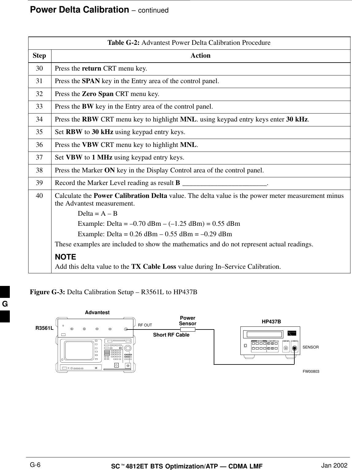
Power Delta Calibration – continuedSCt4812ET BTS Optimization/ATP — CDMA LMF Jan 2002G-6Table G-2: Advantest Power Delta Calibration ProcedureStep Action30 Press the return CRT menu key.31 Press the SPAN key in the Entry area of the control panel.32 Press the Zero Span CRT menu key.33 Press the BW key in the Entry area of the control panel.34 Press the RBW CRT menu key to highlight MNL. using keypad entry keys enter 30 kHz.35 Set RBW to 30 kHz using keypad entry keys.36 Press the VBW CRT menu key to highlight MNL.37 Set VBW to 1 MHz using keypad entry keys.38 Press the Marker ON key in the Display Control area of the control panel.39 Record the Marker Level reading as result B ________________________.40 Calculate the Power Calibration Delta value. The delta value is the power meter measurement minusthe Advantest measurement.Delta = A – BExample: Delta = –0.70 dBm – (–1.25 dBm) = 0.55 dBmExample: Delta = 0.26 dBm – 0.55 dBm = –0.29 dBmThese examples are included to show the mathematics and do not represent actual readings.NOTEAdd this delta value to the TX Cable Loss value during In–Service Calibration. Figure G-3: Delta Calibration Setup – R3561L to HP437BAdvantest PowerSensorRF OUTShort RF CableHP437BSENSORR3561LFW00803G
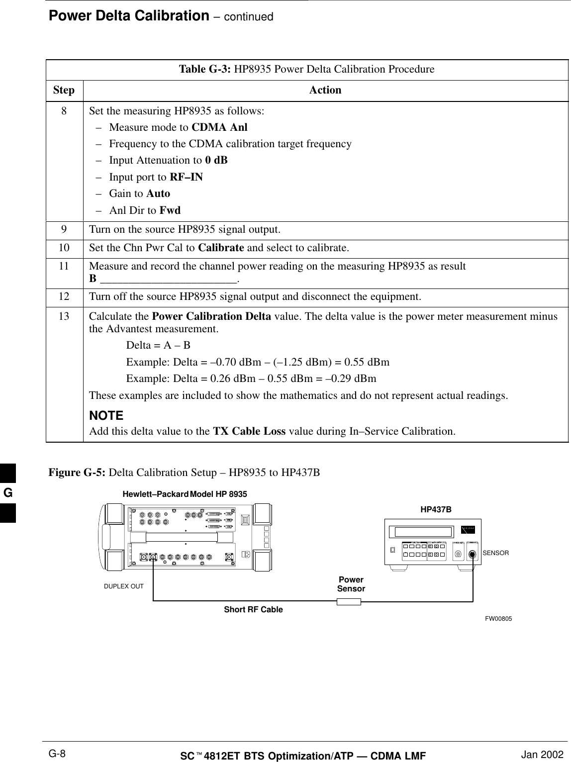
Power Delta Calibration – continuedJan 2002 G-7SCt4812ET BTS Optimization/ATP — CDMA LMFFigure G-4: Delta Calibration Setup – R3561L to R3465R3561LRF OUTINPUTShort RF CableR3465FW00804HP8935 Power DeltaCalibrationFollow the procedure in Table G-3 to perform the HP8935 Power DeltaCalibration procedure.Table G-3: HP8935 Power Delta Calibration ProcedureStep Action* IMPORTANTPerform this procedure after test equipment has been allowed to warm–up and stabilize for a minimumof 60 minutes.1Connect a short RF cable between the HP8935 Duplex Out port and the HP437B power sensor (seeFigure G-5).2Set the HP8935 signal source as follows:–Measure mode to CDMA Gen–Frequency to the CDMA Calibration target frequency–CW RF Path to IQ–Output Port to Dupl–Data Source to Random–Amplitude to 0 dBm3Measure and record the power value reading on the HP437B Power Meter.4Record the Power Meter reading as result A ________________________.5Turn off the source HP8935 signal output, and disconnect the HP437B.NOTELeave the settings on the source HP8935 for convenience in the following steps.6Connect the short RF cable between the source HP8935 Duplex Out port and the RF–IN/OUT port(see Figure G-6).7Ensure that the source HP8935 settings are the same as in Step 2.. . . continued on next pageG
Power Delta Calibration – continuedSCt4812ET BTS Optimization/ATP — CDMA LMF Jan 2002G-8Table G-3: HP8935 Power Delta Calibration ProcedureStep Action8Set the measuring HP8935 as follows:–Measure mode to CDMA Anl–Frequency to the CDMA calibration target frequency–Input Attenuation to 0 dB–Input port to RF–IN–Gain to Auto–Anl Dir to Fwd9Turn on the source HP8935 signal output.10 Set the Chn Pwr Cal to Calibrate and select to calibrate.11 Measure and record the channel power reading on the measuring HP8935 as resultB ________________________.12 Turn off the source HP8935 signal output and disconnect the equipment.13 Calculate the Power Calibration Delta value. The delta value is the power meter measurement minusthe Advantest measurement.Delta = A – BExample: Delta = –0.70 dBm – (–1.25 dBm) = 0.55 dBmExample: Delta = 0.26 dBm – 0.55 dBm = –0.29 dBmThese examples are included to show the mathematics and do not represent actual readings.NOTEAdd this delta value to the TX Cable Loss value during In–Service Calibration. Figure G-5: Delta Calibration Setup – HP8935 to HP437BPowerSensorHewlett–Packard Model HP 8935DUPLEX OUTShort RF CableHP437BSENSORFW00805G
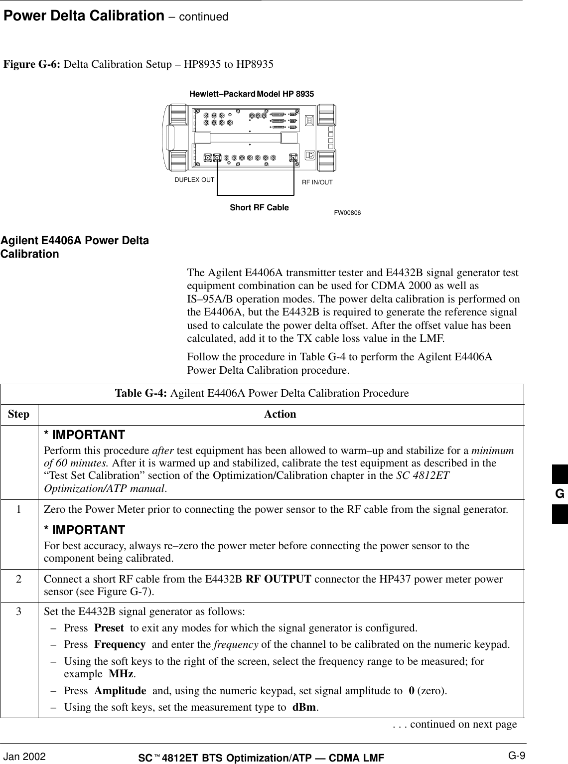
Power Delta Calibration – continuedJan 2002 G-9SCt4812ET BTS Optimization/ATP — CDMA LMFFigure G-6: Delta Calibration Setup – HP8935 to HP8935Hewlett–Packard Model HP 8935Short RF CableDUPLEX OUT RF IN/OUTFW00806Agilent E4406A Power DeltaCalibrationThe Agilent E4406A transmitter tester and E4432B signal generator testequipment combination can be used for CDMA 2000 as well asIS–95A/B operation modes. The power delta calibration is performed onthe E4406A, but the E4432B is required to generate the reference signalused to calculate the power delta offset. After the offset value has beencalculated, add it to the TX cable loss value in the LMF.Follow the procedure in Table G-4 to perform the Agilent E4406APower Delta Calibration procedure.Table G-4: Agilent E4406A Power Delta Calibration ProcedureStep Action* IMPORTANTPerform this procedure after test equipment has been allowed to warm–up and stabilize for a minimumof 60 minutes. After it is warmed up and stabilized, calibrate the test equipment as described in the“Test Set Calibration” section of the Optimization/Calibration chapter in the SC 4812ETOptimization/ATP manual.1Zero the Power Meter prior to connecting the power sensor to the RF cable from the signal generator.* IMPORTANTFor best accuracy, always re–zero the power meter before connecting the power sensor to thecomponent being calibrated.2Connect a short RF cable from the E4432B RF OUTPUT connector the HP437 power meter powersensor (see Figure G-7).3Set the E4432B signal generator as follows:–Press  Preset  to exit any modes for which the signal generator is configured.–Press  Frequency  and enter the frequency of the channel to be calibrated on the numeric keypad.–Using the soft keys to the right of the screen, select the frequency range to be measured; forexample  MHz.–Press  Amplitude  and, using the numeric keypad, set signal amplitude to  0 (zero).–Using the soft keys, set the measurement type to  dBm.. . . continued on next pageG
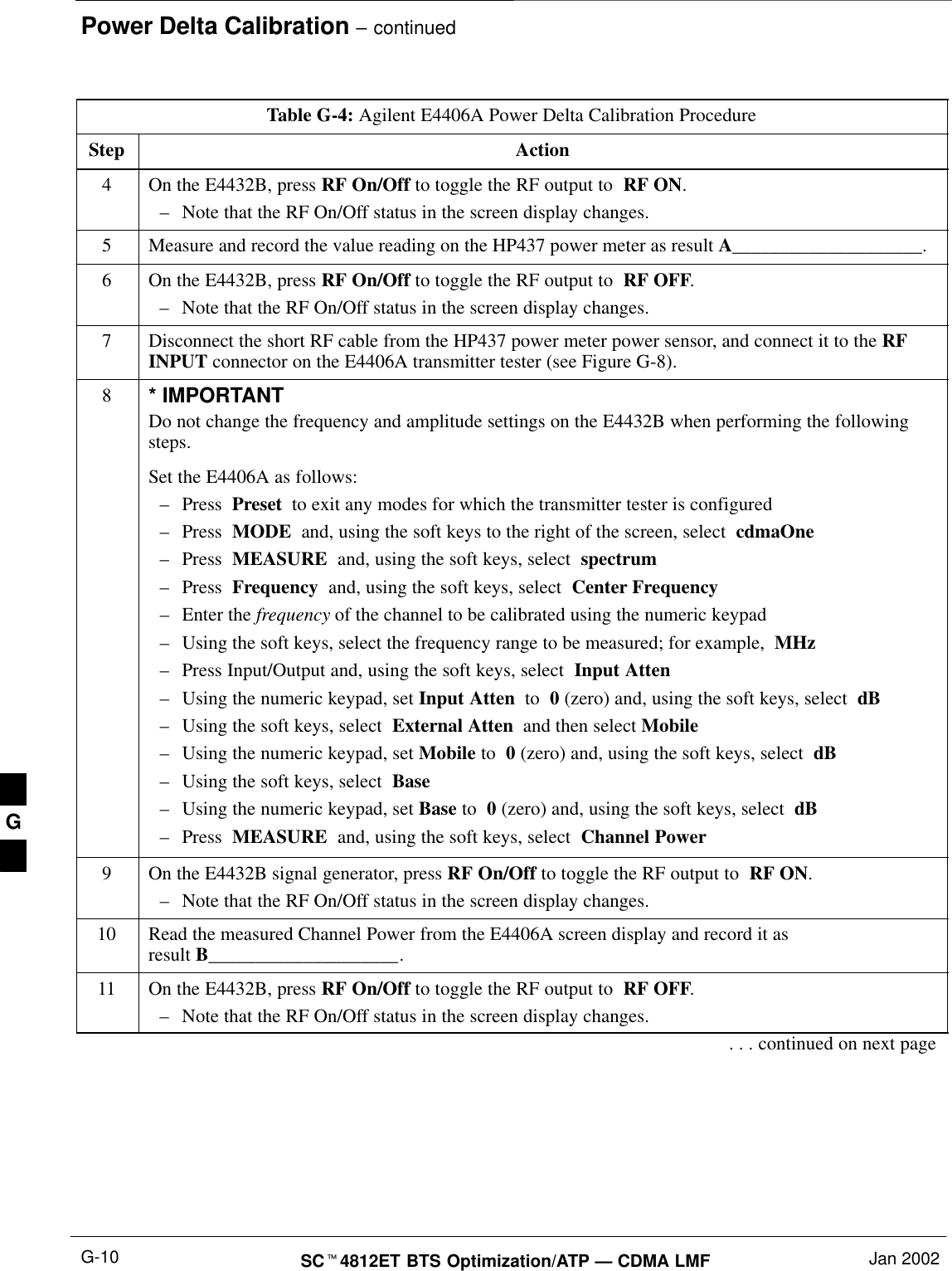
Power Delta Calibration – continuedSCt4812ET BTS Optimization/ATP — CDMA LMF Jan 2002G-10Table G-4: Agilent E4406A Power Delta Calibration ProcedureStep Action4On the E4432B, press RF On/Off to toggle the RF output to  RF ON.–Note that the RF On/Off status in the screen display changes.5Measure and record the value reading on the HP437 power meter as result A____________________.6On the E4432B, press RF On/Off to toggle the RF output to  RF OFF.–Note that the RF On/Off status in the screen display changes.7Disconnect the short RF cable from the HP437 power meter power sensor, and connect it to the RFINPUT connector on the E4406A transmitter tester (see Figure G-8).8* IMPORTANTDo not change the frequency and amplitude settings on the E4432B when performing the followingsteps.Set the E4406A as follows:–Press  Preset  to exit any modes for which the transmitter tester is configured–Press  MODE  and, using the soft keys to the right of the screen, select  cdmaOne–Press  MEASURE  and, using the soft keys, select  spectrum–Press  Frequency  and, using the soft keys, select  Center Frequency–Enter the frequency of the channel to be calibrated using the numeric keypad–Using the soft keys, select the frequency range to be measured; for example,  MHz–Press Input/Output and, using the soft keys, select  Input Atten–Using the numeric keypad, set Input Atten  to  0 (zero) and, using the soft keys, select  dB–Using the soft keys, select  External Atten  and then select Mobile–Using the numeric keypad, set Mobile to  0 (zero) and, using the soft keys, select  dB–Using the soft keys, select  Base–Using the numeric keypad, set Base to  0 (zero) and, using the soft keys, select  dB–Press  MEASURE  and, using the soft keys, select  Channel Power9On the E4432B signal generator, press RF On/Off to toggle the RF output to  RF ON.–Note that the RF On/Off status in the screen display changes.10 Read the measured Channel Power from the E4406A screen display and record it as result B____________________.11 On the E4432B, press RF On/Off to toggle the RF output to  RF OFF.–Note that the RF On/Off status in the screen display changes.. . . continued on next pageG
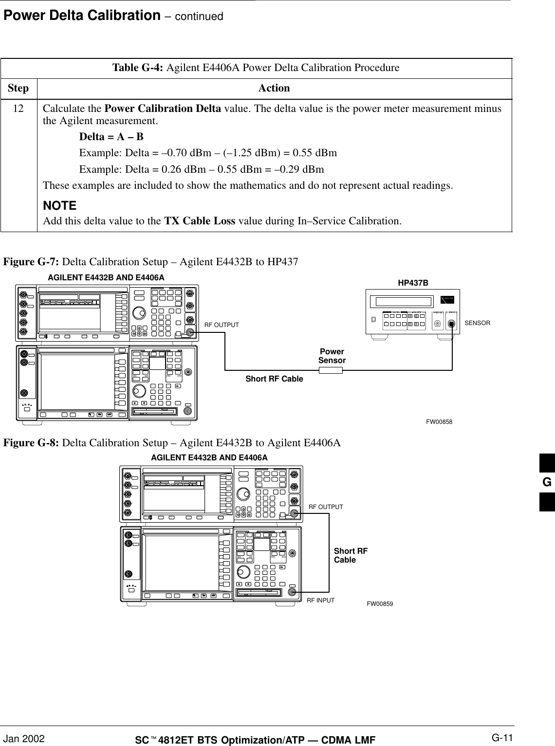
Power Delta Calibration – continuedJan 2002 G-11SCt4812ET BTS Optimization/ATP — CDMA LMFTable G-4: Agilent E4406A Power Delta Calibration ProcedureStep Action12 Calculate the Power Calibration Delta value. The delta value is the power meter measurement minusthe Agilent measurement.Delta = A – BExample: Delta = –0.70 dBm – (–1.25 dBm) = 0.55 dBmExample: Delta = 0.26 dBm – 0.55 dBm = –0.29 dBmThese examples are included to show the mathematics and do not represent actual readings.NOTEAdd this delta value to the TX Cable Loss value during In–Service Calibration. Figure G-7: Delta Calibration Setup – Agilent E4432B to HP437PowerSensorAGILENT E4432B AND E4406AShort RF CableHP437BSENSORRF OUTPUTFW00858Figure G-8: Delta Calibration Setup – Agilent E4432B to Agilent E4406AShort RFCableRF INPUTAGILENT E4432B AND E4406ARF OUTPUTFW00859G
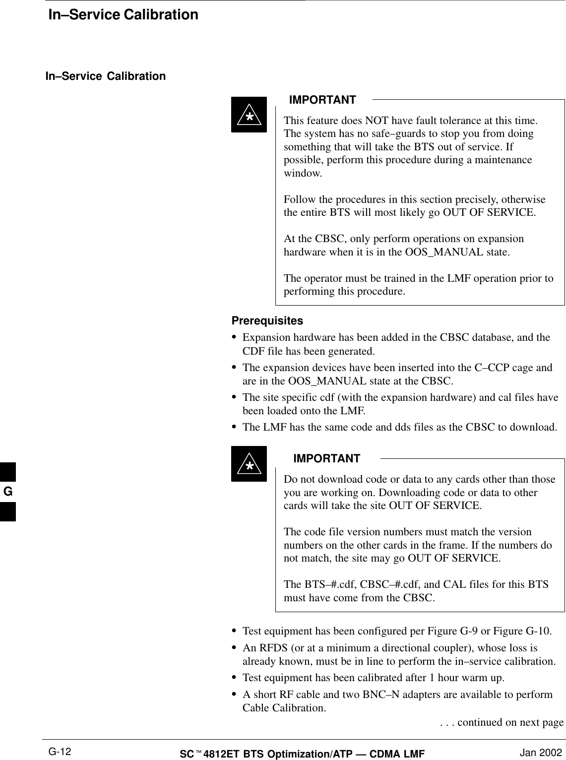
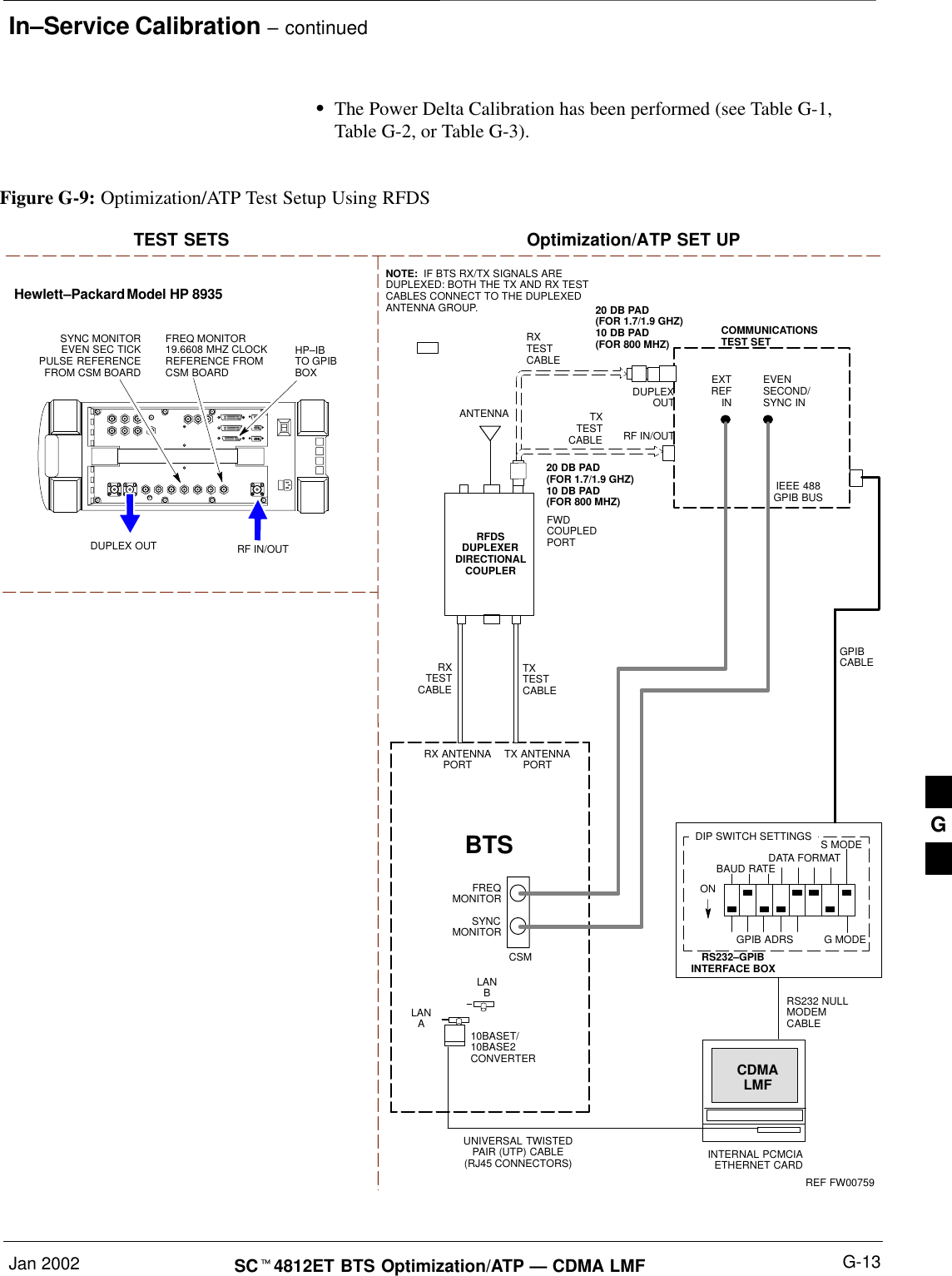
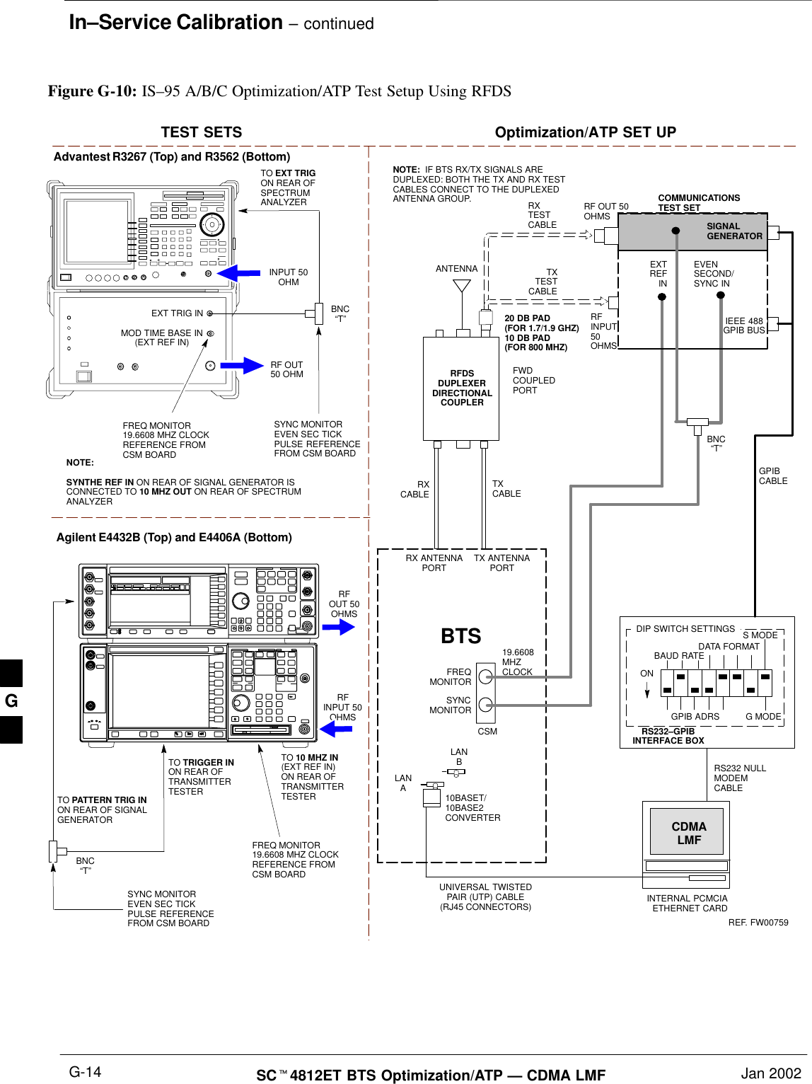
In–Service CalibrationSCt4812ET BTS Optimization/ATP — CDMA LMF Jan 2002G-12In–Service CalibrationThis feature does NOT have fault tolerance at this time.The system has no safe–guards to stop you from doingsomething that will take the BTS out of service. Ifpossible, perform this procedure during a maintenancewindow.Follow the procedures in this section precisely, otherwisethe entire BTS will most likely go OUT OF SERVICE. At the CBSC, only perform operations on expansionhardware when it is in the OOS_MANUAL state.The operator must be trained in the LMF operation prior toperforming this procedure.IMPORTANT*PrerequisitesSExpansion hardware has been added in the CBSC database, and theCDF file has been generated.SThe expansion devices have been inserted into the C–CCP cage andare in the OOS_MANUAL state at the CBSC.SThe site specific cdf (with the expansion hardware) and cal files havebeen loaded onto the LMF.SThe LMF has the same code and dds files as the CBSC to download.Do not download code or data to any cards other than thoseyou are working on. Downloading code or data to othercards will take the site OUT OF SERVICE.The code file version numbers must match the versionnumbers on the other cards in the frame. If the numbers donot match, the site may go OUT OF SERVICE.The BTS–#.cdf, CBSC–#.cdf, and CAL files for this BTSmust have come from the CBSC.IMPORTANT*STest equipment has been configured per Figure G-9 or Figure G-10.SAn RFDS (or at a minimum a directional coupler), whose loss isalready known, must be in line to perform the in–service calibration.STest equipment has been calibrated after 1 hour warm up.SA short RF cable and two BNC–N adapters are available to performCable Calibration. . . . continued on next pageG
In–Service Calibration – continuedJan 2002 G-13SCt4812ET BTS Optimization/ATP — CDMA LMFSThe Power Delta Calibration has been performed (see Table G-1,Table G-2, or Table G-3).TXTESTCABLEHewlett–Packard Model HP 8935DUPLEX OUTTEST SETS Optimization/ATP SET UPRF IN/OUTHP–IBTO GPIBBOXRX ANTENNAPORT TX ANTENNAPORTRS232–GPIBINTERFACE BOXINTERNAL PCMCIAETHERNET CARDGPIBCABLEUNIVERSAL TWISTEDPAIR (UTP) CABLE(RJ45 CONNECTORS)RS232 NULLMODEMCABLES MODEDATA FORMATBAUD RATEGPIB ADRS G MODEONBTSTXTESTCABLECDMALMFDIP SWITCH SETTINGS10BASET/10BASE2CONVERTERLANBLANARXTESTCABLECOMMUNICATIONSTEST SETIEEE 488GPIB BUSRF IN/OUTNOTE:  IF BTS RX/TX SIGNALS AREDUPLEXED: BOTH THE TX AND RX TESTCABLES CONNECT TO THE DUPLEXEDANTENNA GROUP.ANTENNARFDSDUPLEXERDIRECTIONALCOUPLEREVENSECOND/SYNC INEXTREF INFREQMONITORSYNCMONITORCSMREF FW00759SYNC MONITOREVEN SEC TICKPULSE REFERENCEFROM CSM BOARDFREQ MONITOR19.6608 MHZ CLOCKREFERENCE FROMCSM BOARDRXTESTCABLEFWDCOUPLEDPORTFigure G-9: Optimization/ATP Test Setup Using RFDS20 DB PAD(FOR 1.7/1.9 GHZ)10 DB PAD(FOR 800 MHZ)20 DB PAD(FOR 1.7/1.9 GHZ)10 DB PAD(FOR 800 MHZ)DUPLEXOUTG
In–Service Calibration – continuedSCt4812ET BTS Optimization/ATP — CDMA LMF Jan 2002G-14TEST SETS Optimization/ATP SET UPFigure G-10: IS–95 A/B/C Optimization/ATP Test Setup Using RFDSRFINPUT 50OHMSRFOUT 50OHMSAgilent E4432B (Top) and E4406A (Bottom)FREQ MONITOR19.6608 MHZ CLOCKREFERENCE FROMCSM BOARDSYNC MONITOREVEN SEC TICKPULSE REFERENCEFROM CSM BOARDBNC“T”TO TRIGGER INON REAR OFTRANSMITTERTESTERTO PATTERN TRIG INON REAR OF SIGNALGENERATORTO 10 MHZ IN(EXT REF IN) ON REAR OFTRANSMITTERTESTER INPUT 50OHMRF OUT50 OHMAdvantest R3267 (Top) and R3562 (Bottom)FREQ MONITOR19.6608 MHZ CLOCKREFERENCE FROMCSM BOARDSYNC MONITOREVEN SEC TICKPULSE REFERENCEFROM CSM BOARDBNC“T”NOTE:SYNTHE REF IN ON REAR OF SIGNAL GENERATOR ISCONNECTED TO 10 MHZ OUT ON REAR OF SPECTRUMANALYZERTO EXT TRIG ON REAR OFSPECTRUMANALYZERTXTESTCABLERX ANTENNAPORT TX ANTENNAPORTRS232–GPIBINTERFACE BOXINTERNAL PCMCIAETHERNET CARDGPIBCABLEUNIVERSAL TWISTEDPAIR (UTP) CABLE(RJ45 CONNECTORS)RS232 NULLMODEMCABLES MODEDATA FORMATBAUD RATEGPIB ADRS G MODEONBTSTXCABLECDMALMFDIP SWITCH SETTINGS10BASET/10BASE2CONVERTERLANBLANARXTESTCABLECOMMUNICATIONSTEST SETIEEE 488GPIB BUSRFINPUT50OHMSRF OUT 50OHMSNOTE:  IF BTS RX/TX SIGNALS AREDUPLEXED: BOTH THE TX AND RX TESTCABLES CONNECT TO THE DUPLEXEDANTENNA GROUP.ANTENNARFDSDUPLEXERDIRECTIONALCOUPLEREVENSECOND/SYNC INEXTREF INFREQMONITORSYNCMONITORCSMREF. FW00759RXCABLEFWDCOUPLEDPORTSIGNALGENERATOREXT TRIG INMOD TIME BASE IN(EXT REF IN)19.6608MHZCLOCK20 DB PAD(FOR 1.7/1.9 GHZ)10 DB PAD(FOR 800 MHZ)BNC“T”G
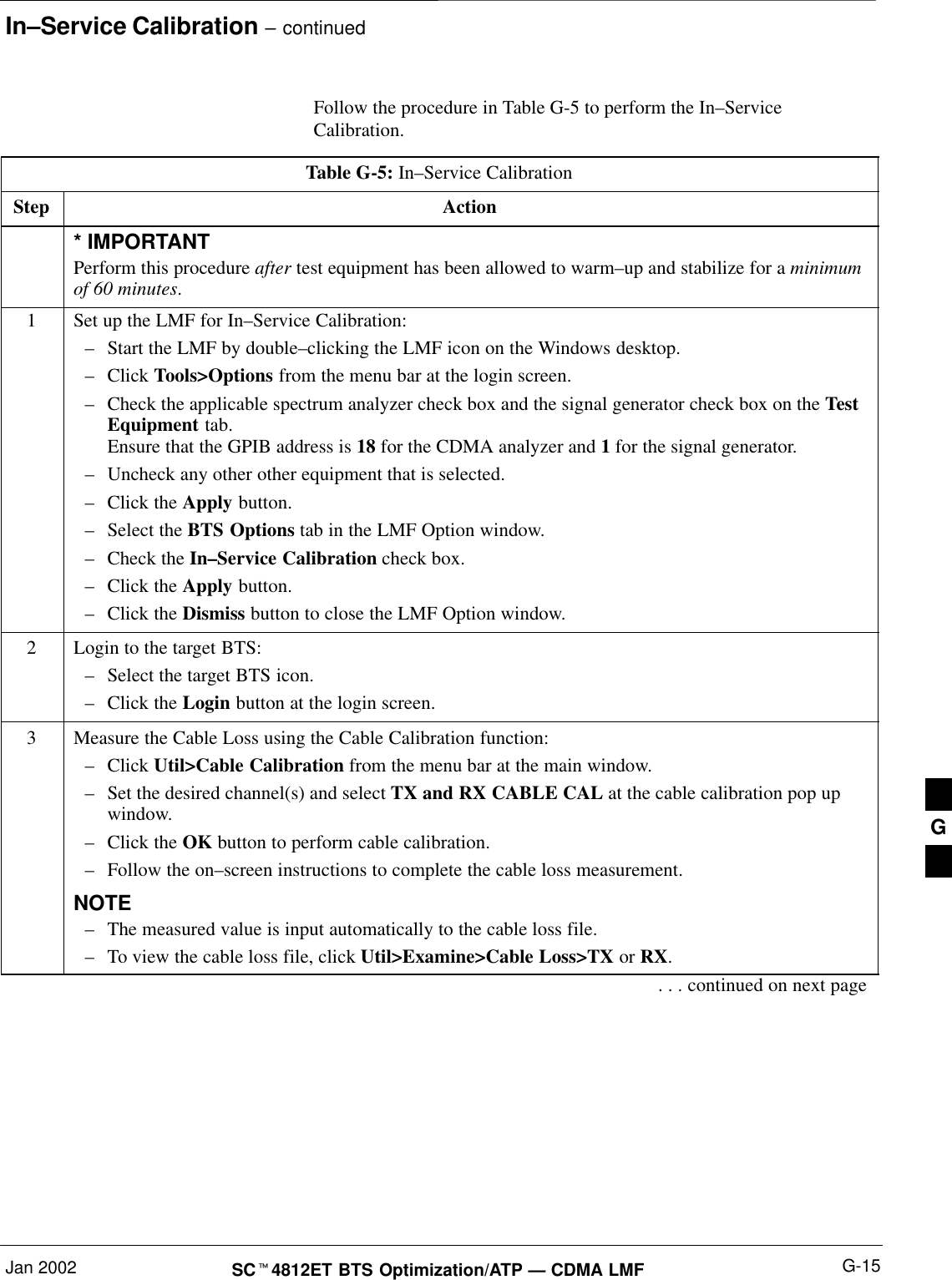
In–Service Calibration – continuedJan 2002 G-15SCt4812ET BTS Optimization/ATP — CDMA LMFFollow the procedure in Table G-5 to perform the In–ServiceCalibration.Table G-5: In–Service CalibrationStep Action* IMPORTANTPerform this procedure after test equipment has been allowed to warm–up and stabilize for a minimumof 60 minutes.1Set up the LMF for In–Service Calibration:–Start the LMF by double–clicking the LMF icon on the Windows desktop.–Click Tools>Options from the menu bar at the login screen.–Check the applicable spectrum analyzer check box and the signal generator check box on the TestEquipment tab.Ensure that the GPIB address is 18 for the CDMA analyzer and 1 for the signal generator.–Uncheck any other other equipment that is selected.–Click the Apply button.–Select the BTS Options tab in the LMF Option window.–Check the In–Service Calibration check box.–Click the Apply button.–Click the Dismiss button to close the LMF Option window.2Login to the target BTS:–Select the target BTS icon.–Click the Login button at the login screen.3Measure the Cable Loss using the Cable Calibration function:–Click Util>Cable Calibration from the menu bar at the main window.–Set the desired channel(s) and select TX and RX CABLE CAL at the cable calibration pop upwindow.–Click the OK button to perform cable calibration.–Follow the on–screen instructions to complete the cable loss measurement.NOTE–The measured value is input automatically to the cable loss file.–To view the cable loss file, click Util>Examine>Cable Loss>TX or RX.. . . continued on next pageG
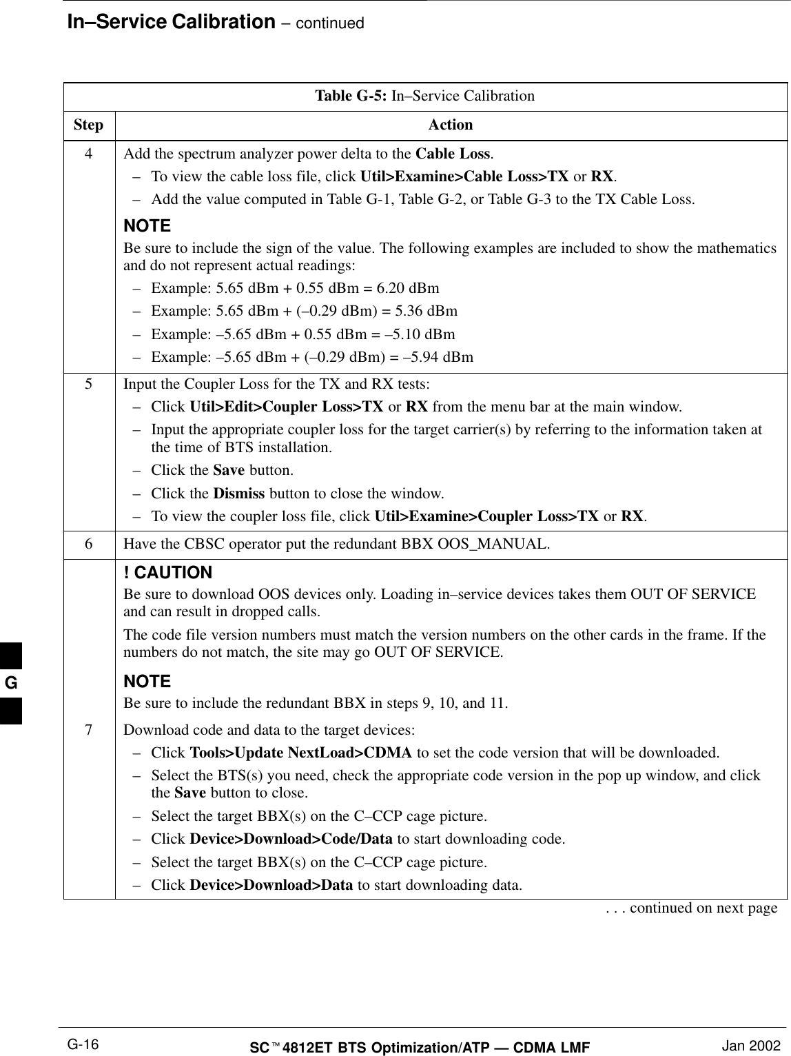
In–Service Calibration – continuedSCt4812ET BTS Optimization/ATP — CDMA LMF Jan 2002G-16Table G-5: In–Service CalibrationStep Action4Add the spectrum analyzer power delta to the Cable Loss.–To view the cable loss file, click Util>Examine>Cable Loss>TX or RX.–Add the value computed in Table G-1, Table G-2, or Table G-3 to the TX Cable Loss.NOTEBe sure to include the sign of the value. The following examples are included to show the mathematicsand do not represent actual readings:–Example: 5.65 dBm + 0.55 dBm = 6.20 dBm–Example: 5.65 dBm + (–0.29 dBm) = 5.36 dBm–Example: –5.65 dBm + 0.55 dBm = –5.10 dBm–Example: –5.65 dBm + (–0.29 dBm) = –5.94 dBm5Input the Coupler Loss for the TX and RX tests:–Click Util>Edit>Coupler Loss>TX or RX from the menu bar at the main window.–Input the appropriate coupler loss for the target carrier(s) by referring to the information taken atthe time of BTS installation.–Click the Save button.–Click the Dismiss button to close the window.–To view the coupler loss file, click Util>Examine>Coupler Loss>TX or RX.6Have the CBSC operator put the redundant BBX OOS_MANUAL.! CAUTIONBe sure to download OOS devices only. Loading in–service devices takes them OUT OF SERVICEand can result in dropped calls.The code file version numbers must match the version numbers on the other cards in the frame. If thenumbers do not match, the site may go OUT OF SERVICE.NOTEBe sure to include the redundant BBX in steps 9, 10, and 11.7Download code and data to the target devices:–Click Tools>Update NextLoad>CDMA to set the code version that will be downloaded.–Select the BTS(s) you need, check the appropriate code version in the pop up window, and clickthe Save button to close.–Select the target BBX(s) on the C–CCP cage picture.–Click Device>Download>Code/Data to start downloading code.–Select the target BBX(s) on the C–CCP cage picture.–Click Device>Download>Data to start downloading data.. . . continued on next pageG
In–Service Calibration – continuedJan 2002 G-17SCt4812ET BTS Optimization/ATP — CDMA LMFTable G-5: In–Service CalibrationStep Action! CAUTIONPerform the In–service Calibration procedure on OOS devices only.8Select the desired test:–Select the target BBX(s) on the C–CCP cage picture.–Click Tests>[desired test] from the menu bar at the main window.–Select the target carrier and confirm the channel number in the pop up window.–Leave the Verify BLO check box checked.–From the Test Pattern pick list, select a test pattern.–Click the OK button to start calibration.–Follow the on–screen instructions, except, do not connect to the BTS antenna port, connect to thedirectional coupler (fwd) port associated with the on screen prompt antenna port.NOTESSelecting Pilot (default) performs tests using a pilot signal only.SSelecting Standard performs tests using pilot, synch, paging and six traffic channels. This requiresan MCC to be selected.SSelecting CDFPilot performs tests using the CDF value for pilot gain and IS–97 gain values for allthe other channels included in the Standard pattern setting (paging, synch, and six traffic). Usingthis pattern setting requires the selection of both a BBX and at least one MCC.SSelecting CDF performs tests using pilot, synch, paging and six traffic channels, however, the gainfor the channel elements is specified in the CDF file.9Save the result and download the BLO data to the target BBX(s):–Click the Save Result button on the result screen.The window closes automatically.10 Logout from the BTS and close the LMF session:–Click BTS>Logout to close the BTS connection.–Close the LMF window.11 Restore the new “bts–*.cal” file to the CBSC.12 Enable the target device(s) from the CBSC.  G
In–Service Calibration – continuedSCt4812ET BTS Optimization/ATP — CDMA LMF Jan 2002G-18NotesG
Jan 2002 SCt4812ET BTS Optimization/ATP — CDMA LMFAppendix H: RF Cabinet Interconnect Cables Appendix Content SC 4812ET Inter−Cabinet Cabeling HĆ1. . . . . . . . . . . . . . . . . . . . . . . . C−CCP Cables and Cable Connectors HĆ4. . . . . . . . . . . . . . . . . . . . . . RF Cabinet LPA Cables HĆ7. . . . . . . . . . . . . . . . . . . . . . . . . . . . . . . . . . . LPAC Cabling HĆ11. . . . . . . . . . . . . . . . . . . . . . . . . . . . . . . . . . . . . . . . . . . ETIB Cables and Cable Connectors HĆ12. . . . . . . . . . . . . . . . . . . . . . . . . SPAN I/O Cable Connection Diagram HĆ13. . . . . . . . . . . . . . . . . . . . . . . DRDC/TRDC Cables and Cable Connections HĆ15. . . . . . . . . . . . . . . . MPC to DRDC Cabling HĆ20. . . . . . . . . . . . . . . . . . . . . . . . . . . . . . . . . . . RFDS Cabling Details HĆ22. . . . . . . . . . . . . . . . . . . . . . . . . . . . . . . . . . . . 50 Pair Punchblock HĆ25. . . . . . . . . . . . . . . . . . . . . . . . . . . . . . . . . . . . . . . H
Table of Contents  – continuedSCt4812ET BTS Optimization/ATP — CDMA LMF Jan 2002NotesH
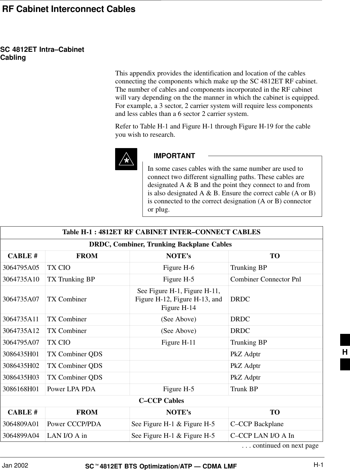
RF Cabinet Interconnect CablesJan 2002 H-1SCt4812ET BTS Optimization/ATP — CDMA LMFSC 4812ET Intra–CabinetCabling This appendix provides the identification and location of the cablesconnecting the components which make up the SC 4812ET RF cabinet.The number of cables and components incorporated in the RF cabinetwill vary depending on the the manner in which the cabinet is equipped.For example, a 3 sector, 2 carrier system will require less componentsand less cables than a 6 sector 2 carrier system.Refer to Table H-1 and Figure H-1 through Figure H-19 for the cableyou wish to research.In some cases cables with the same number are used toconnect two different signalling paths. These cables aredesignated A & B and the point they connect to and fromis also designated A & B. Ensure the correct cable (A or B)is connected to the correct designation (A or B) connectoror plug.IMPORTANT*Table H-1 : 4812ET RF CABINET INTER–CONNECT CABLESDRDC, Combiner, Trunking Backplane CablesCABLE # FROM NOTE’sTO3064795A05 TX CIO Figure H-6 Trunking BP3064735A10 TX Trunking BP Figure H-5 Combiner Connector Pnl3064735A07 TX Combiner See Figure H-1, Figure H-11,Figure H-12, Figure H-13, andFigure H-14DRDC3064735A11 TX Combiner (See Above) DRDC3064735A12 TX Combiner (See Above) DRDC3064795A07 TX CIO Figure H-11 Trunking BP3086435H01 TX Combiner QDS PkZ Adptr3086435H02 TX Combiner QDS PkZ Adptr3086435H03 TX Combiner QDS PkZ Adptr3086168H01 Power LPA PDA Figure H-5 Trunk BPC–CCP CablesCABLE # FROM NOTE’sTO3064809A01 Power CCCP/PDA See Figure H-1 & Figure H-5 C–CCP Backplane3064899A04 LAN I/O A in See Figure H-1 & Figure H-5 C–CCP LAN I/O A In. . . continued on next pageH
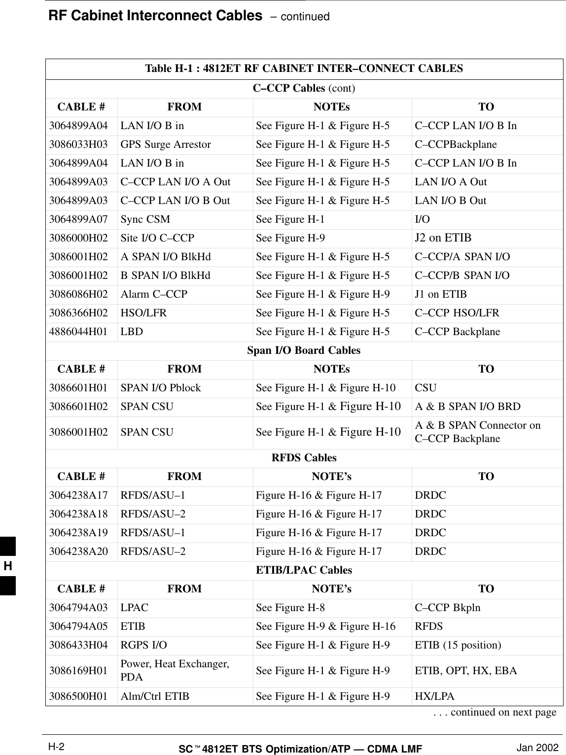
RF Cabinet Interconnect Cables  – continuedSCt4812ET BTS Optimization/ATP — CDMA LMF Jan 2002H-2Table H-1 : 4812ET RF CABINET INTER–CONNECT CABLESC–CCP Cables (cont)CABLE # FROM NOTEs TO3064899A04 LAN I/O B in See Figure H-1 & Figure H-5 C–CCP LAN I/O B In3086033H03 GPS Surge Arrestor See Figure H-1 & Figure H-5 C–CCPBackplane3064899A04 LAN I/O B in See Figure H-1 & Figure H-5 C–CCP LAN I/O B In3064899A03 C–CCP LAN I/O A Out See Figure H-1 & Figure H-5 LAN I/O A Out3064899A03 C–CCP LAN I/O B Out See Figure H-1 & Figure H-5 LAN I/O B Out3064899A07 Sync CSM See Figure H-1 I/O3086000H02 Site I/O C–CCP See Figure H-9 J2 on ETIB3086001H02 A SPAN I/O BlkHd See Figure H-1 & Figure H-5 C–CCP/A SPAN I/O3086001H02 B SPAN I/O BlkHd See Figure H-1 & Figure H-5 C–CCP/B SPAN I/O3086086H02 Alarm C–CCP See Figure H-1 & Figure H-9 J1 on ETIB3086366H02 HSO/LFR See Figure H-1 & Figure H-5 C–CCP HSO/LFR4886044H01 LBD See Figure H-1 & Figure H-5 C–CCP BackplaneSpan I/O Board CablesCABLE # FROM NOTEs TO3086601H01 SPAN I/O Pblock See Figure H-1 & Figure H-10 CSU3086601H02 SPAN CSU See Figure H-1 & Figure H-10 A & B SPAN I/O BRD3086001H02 SPAN CSU See Figure H-1 & Figure H-10 A & B SPAN Connector onC–CCP BackplaneRFDS CablesCABLE # FROM NOTE’sTO3064238A17 RFDS/ASU–1Figure H-16 & Figure H-17 DRDC3064238A18 RFDS/ASU–2Figure H-16 & Figure H-17 DRDC3064238A19 RFDS/ASU–1Figure H-16 & Figure H-17 DRDC3064238A20 RFDS/ASU–2Figure H-16 & Figure H-17 DRDCETIB/LPAC CablesCABLE # FROM NOTE’sTO3064794A03 LPAC See Figure H-8 C–CCP Bkpln3064794A05 ETIB See Figure H-9 & Figure H-16 RFDS3086433H04 RGPS I/O See Figure H-1 & Figure H-9 ETIB (15 position)3086169H01 Power, Heat Exchanger,PDA See Figure H-1 & Figure H-9 ETIB, OPT, HX, EBA3086500H01 Alm/Ctrl ETIB See Figure H-1 & Figure H-9 HX/LPA. . . continued on next pageH
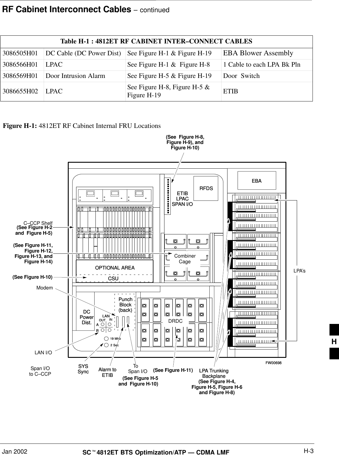
RF Cabinet Interconnect Cables – continuedJan 2002 H-3SCt4812ET BTS Optimization/ATP — CDMA LMFTable H-1 : 4812ET RF CABINET INTER–CONNECT CABLES3086505H01 DC Cable (DC Power Dist) See Figure H-1 & Figure H-19 EBA Blower Assembly3086566H01 LPAC See Figure H-1 &  Figure H-8 1 Cable to each LPA Bk Pln3086569H01 Door Intrusion Alarm See Figure H-5 & Figure H-19 Door  Switch3086655H02 LPAC See Figure H-8, Figure H-5 &Figure H-19 ETIB Figure H-1: 4812ET RF Cabinet Internal FRU LocationsLPA’sLPA TrunkingBackplaneRFDSDCPowerDist.PunchBlock(back)EBAOPTIONAL AREASpan I/OAlarm toETIBETIBLPACSPAN I/OABINOUTLAN19 MHz2 SecCSU(See  Figure H-8,Figure H-9), andFigure H-10)(See Figure H-4,Figure H-5, Figure H-6and Figure H-8)DRDCFW00698SYSSync LPA TrunkingBackplaneRFDSDCPowerDist.PunchBlock(back)EBAC–CCP ShelfCombinerCageOPTIONAL AREASpan I/Oto C–CCP Alarm toETIBETIBLPACSPAN I/OABINOUTLANLAN I/O19 MHz2 SecCSU(See Figure H-2and  Figure H-5)(See Figure H-11,Figure H-12,Figure H-13, andFigure H-14)(See Figure H-11)(See Figure H-10)DRDCFW00698SYSSync(See Figure H-5and  Figure H-10)ModemToH
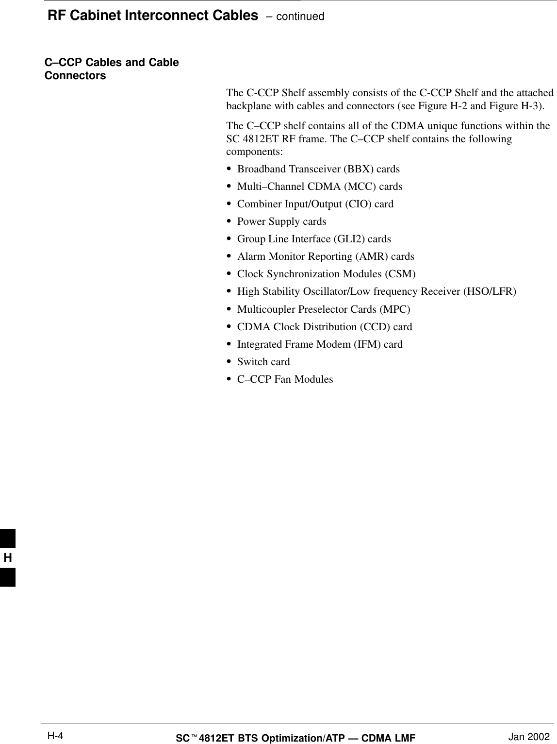
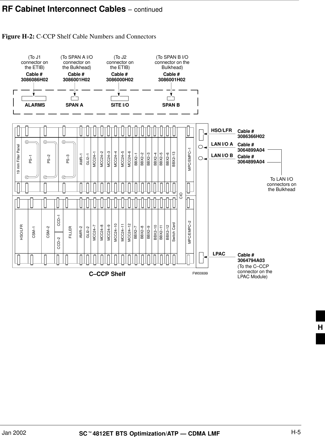
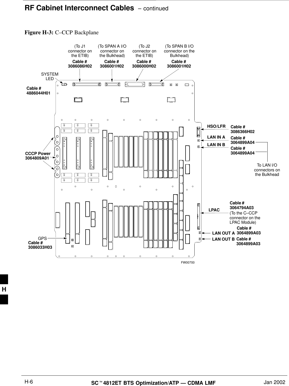
RF Cabinet Interconnect Cables  – continuedSCt4812ET BTS Optimization/ATP — CDMA LMF Jan 2002H-4C–CCP Cables and CableConnectorsThe C-CCP Shelf assembly consists of the C-CCP Shelf and the attachedbackplane with cables and connectors (see Figure H-2 and Figure H-3).The C–CCP shelf contains all of the CDMA unique functions within theSC 4812ET RF frame. The C–CCP shelf contains the followingcomponents:SBroadband Transceiver (BBX) cardsSMulti–Channel CDMA (MCC) cardsSCombiner Input/Output (CIO) cardSPower Supply cardsSGroup Line Interface (GLI2) cardsSAlarm Monitor Reporting (AMR) cardsSClock Synchronization Modules (CSM)SHigh Stability Oscillator/Low frequency Receiver (HSO/LFR)SMulticoupler Preselector Cards (MPC)SCDMA Clock Distribution (CCD) cardSIntegrated Frame Modem (IFM) cardSSwitch cardSC–CCP Fan ModulesH
RF Cabinet Interconnect Cables – continuedJan 2002 H-5SCt4812ET BTS Optimization/ATP — CDMA LMFFigure H-2: C-CCP Shelf Cable Numbers and ConnectorsPS–3AMR–1HSO/LFRCSM–1CSM–2FILLERAMR–2GLI2–1GLI2–2MCC24–6BBX2–1BBX2–2BBX2–3BBX2–4BBX2–5BBX2–6BBX2–13Switch CardMPC/EMPC–1MPC/EMPC–2CIOBBX2–7BBX2–8BBX2–9BBX2–10BBX2–11BBX2–12MCC24–5MCC24–4MCC24–3MCC24–2MCC24–1MCC24–12MCC24–11MCC24–10MCC24–9MCC24–8MCC24–7PS–2PS–1CCD–2 CCD–119 mm Filter PanelC–CCP ShelfSPAN A SPAN BCable #3064794A03Cable #3086366H02Cable #3064899A04Cable #3064899A04LPACALARMS SITE I/OHSO/LFRLAN I/O ALAN I/O BCable #3086001H02Cable #3086000H02Cable #3086001H02Cable #3086086H02To LAN I/Oconnectors onthe Bulkhead(To J1connector onthe ETIB)(To SPAN A I/Oconnector onthe Bulkhead)(To SPAN B I/Oconnector on theBulkhead)(To J2connector onthe ETIB)(To the C–CCPconnector on theLPAC Module)FW00699H
RF Cabinet Interconnect Cables  – continuedSCt4812ET BTS Optimization/ATP — CDMA LMF Jan 2002H-6SYSTEMLEDLAN OUT BGPSFigure H-3: C–CCP BackplaneFW00700Cable #3064794A03Cable #3086366H02Cable #3064899A04Cable #3064899A04LPACHSO/LFRLAN IN ALAN IN BCable #3086001H02Cable #3086000H02Cable #3086001H02Cable #3086086H02To LAN I/Oconnectors onthe Bulkhead(To J1connector onthe ETIB)(To SPAN A I/Oconnector onthe Bulkhead)(To SPAN B I/Oconnector on theBulkhead)(To J2connector onthe ETIB)(To the C–CCPconnector on theLPAC Module)CCCP Power3064809A01LAN OUT A Cable #3064899A03Cable #3064899A03Cable #3086033H03Cable #4886044H01H
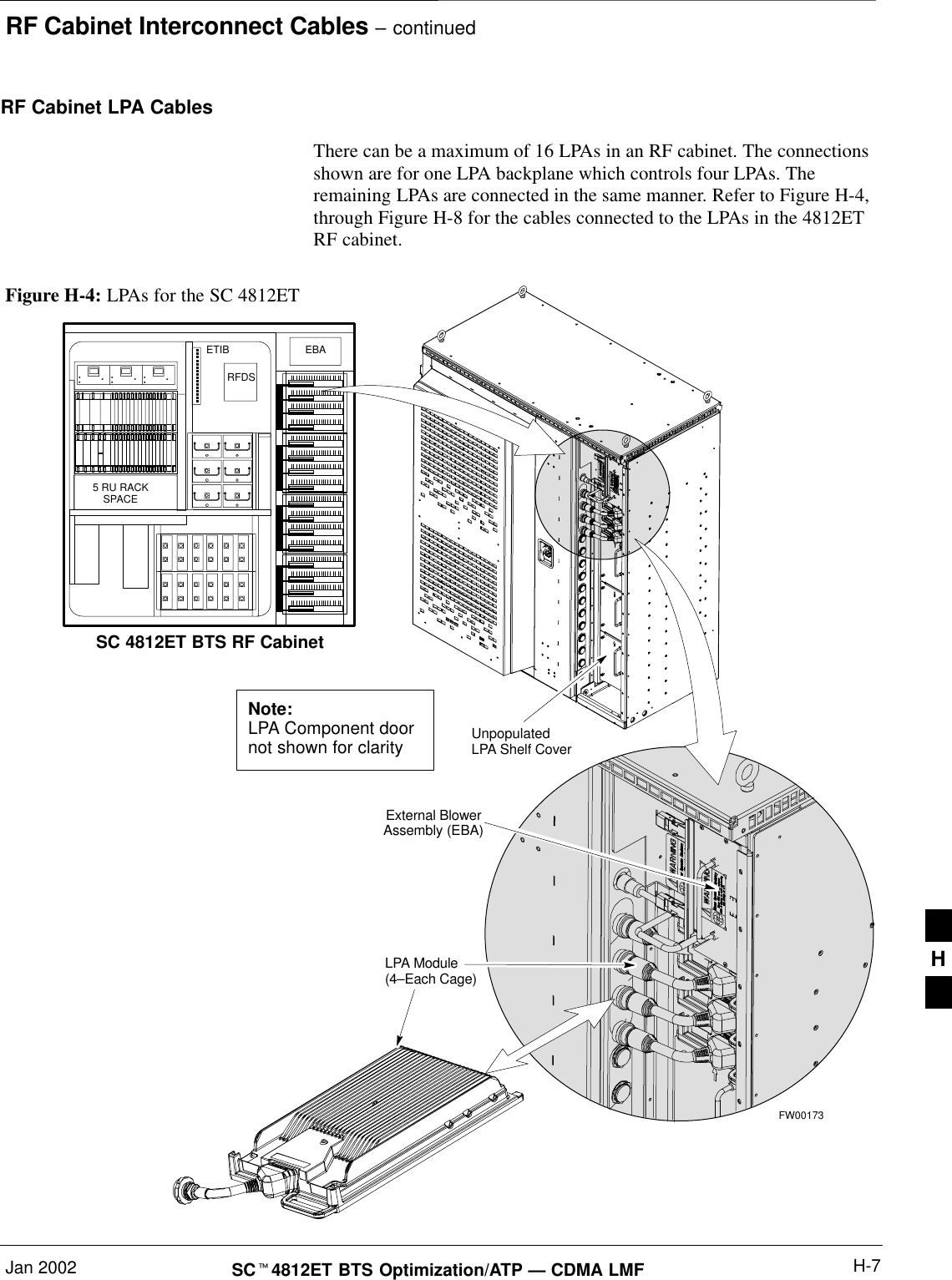
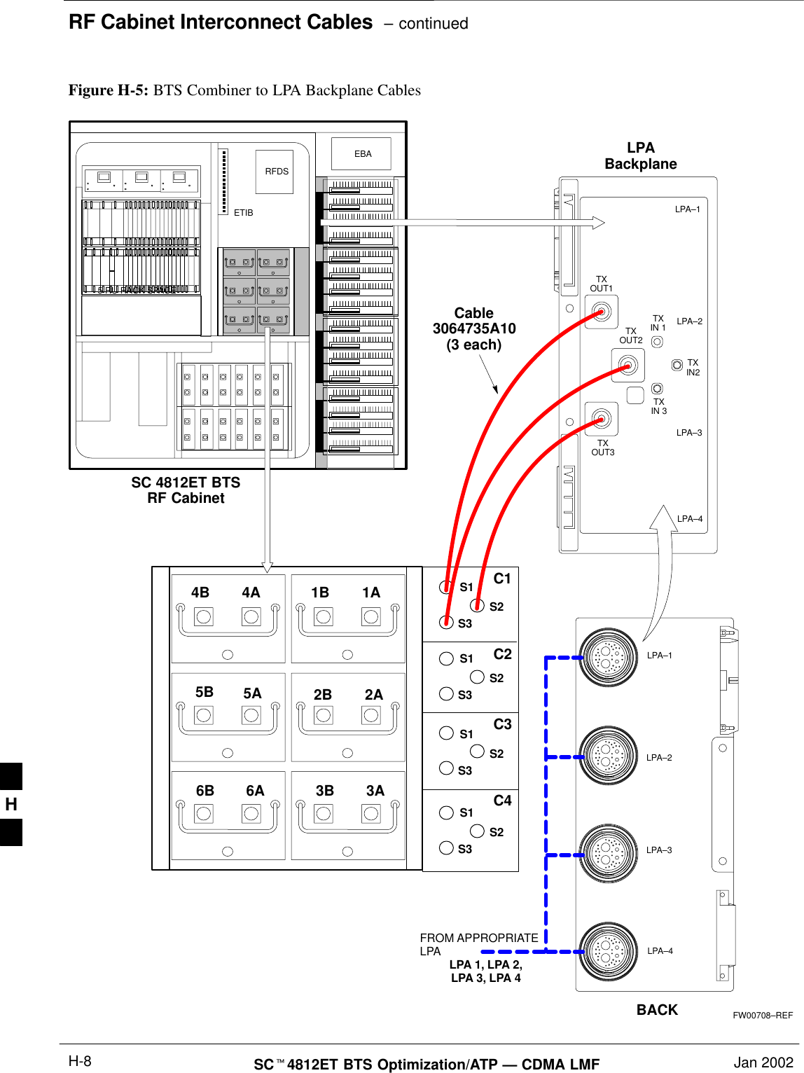
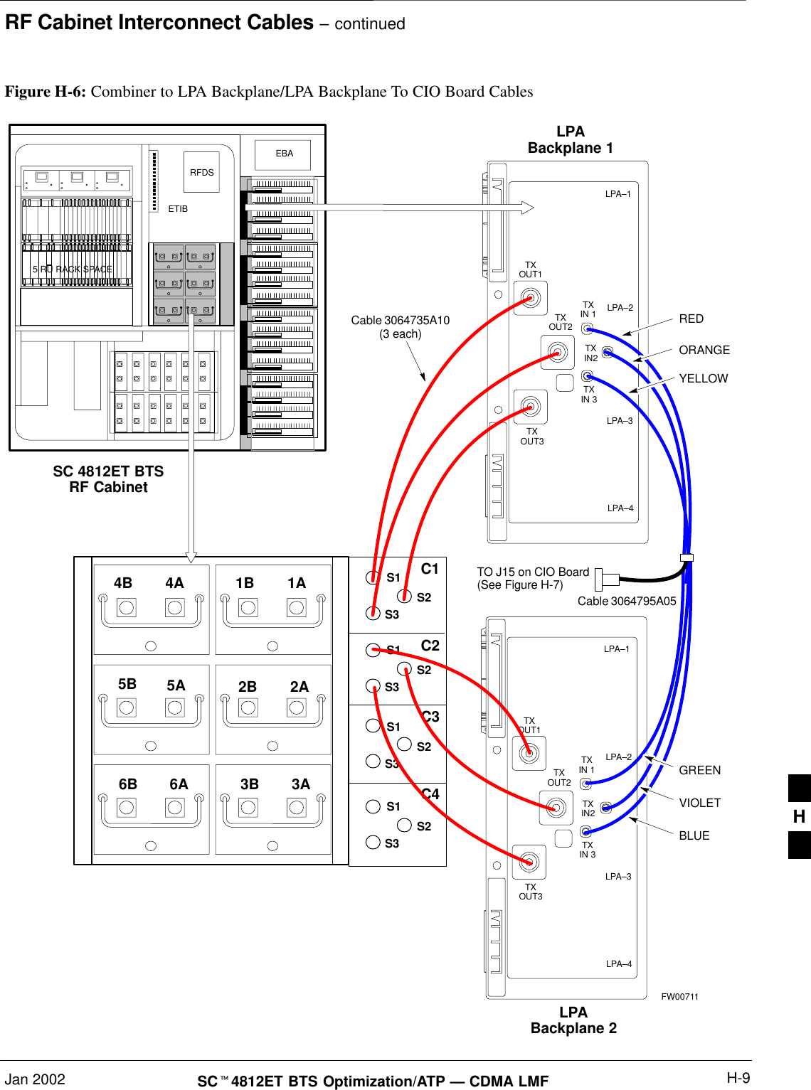
RF Cabinet Interconnect Cables – continuedJan 2002 H-7SCt4812ET BTS Optimization/ATP — CDMA LMFRF Cabinet LPA Cables There can be a maximum of 16 LPAs in an RF cabinet. The connectionsshown are for one LPA backplane which controls four LPAs. Theremaining LPAs are connected in the same manner. Refer to Figure H-4,through Figure H-8 for the cables connected to the LPAs in the 4812ETRF cabinet.Figure H-4: LPAs for the SC 4812ET5 RU RACKSPACERFDSEBAETIBUnpopulatedLPA Shelf CoverLPA Module(4–Each Cage)External BlowerAssembly (EBA)Note:LPA Component doornot shown for claritySC 4812ET BTS RF CabinetFW00173H
RF Cabinet Interconnect Cables  – continuedSCt4812ET BTS Optimization/ATP — CDMA LMF Jan 2002H-85 RU RACK SPACERFDSEBAETIBSC 4812ET BTSRF CabinetFW00708–REFFigure H-5: BTS Combiner to LPA Backplane CablesC1C2C3C4S1S2S3LPA–1LPA–2LPA–3LPA–4TXOUT1TXOUT2TXOUT3TXIN 3TXIN2TXIN 1Cable3064735A10(3 each)LPABackplane4A4B5A5B6A6B1A1B2A2B3A3BS1S2S3S1S2S3S1S2S3BACKLPA–1LPA–2LPA–3LPA–4FROM APPROPRIATELPA LPA 1, LPA 2,LPA 3, LPA 4H
RF Cabinet Interconnect Cables – continuedJan 2002 H-9SCt4812ET BTS Optimization/ATP — CDMA LMFTO J15 on CIO Board(See Figure H-7)5 RU RACK SPACERFDSEBAETIBSC 4812ET BTSRF CabinetFW00711Figure H-6: Combiner to LPA Backplane/LPA Backplane To CIO Board CablesC1C2C3C4S1S2S3LPA–1LPA–2LPA–3LPA–4TXOUT1TXOUT2TXOUT3TXIN 3TXIN2TXIN 1Cable 3064735A10(3 each)LPABackplane 14A4B5A5B6A6B1A1B2A2B3A3BS1S2S3S1S2S3S1S2S3 BLUEGREENVIOLETLPA–1LPA–2LPA–3LPA–4TXOUT1TXOUT2TXOUT3TXIN 3TXIN2TXIN 1LPABackplane 2REDYELLOWORANGECable 3064795A05H
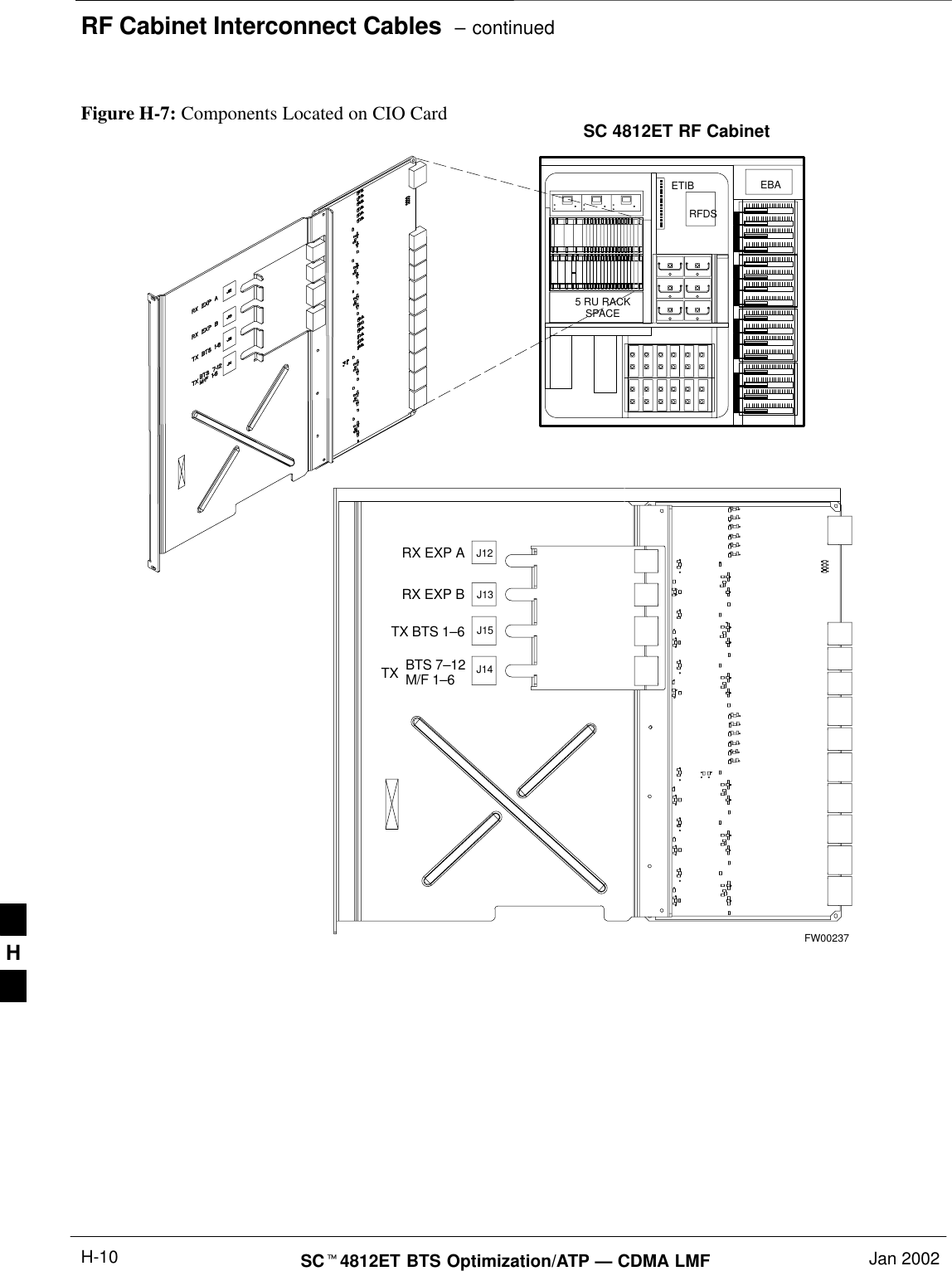
RF Cabinet Interconnect Cables  – continuedSCt4812ET BTS Optimization/ATP — CDMA LMF Jan 2002H-10Figure H-7: Components Located on CIO CardRX EXP ARX EXP BTX BTS 1–6J12J13J14J15BTS 7–12M/F 1–6TXSC 4812ET RF CabinetFW002375 RU RACKSPACERFDSEBAETIBH
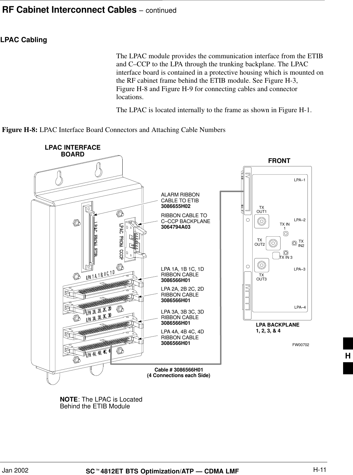
RF Cabinet Interconnect Cables – continuedJan 2002 H-11SCt4812ET BTS Optimization/ATP — CDMA LMFLPAC Cabling The LPAC module provides the communication interface from the ETIBand C–CCP to the LPA through the trunking backplane. The LPACinterface board is contained in a protective housing which is mounted onthe RF cabinet frame behind the ETIB module. See Figure H-3,Figure H-8 and Figure H-9 for connecting cables and connectorlocations.The LPAC is located internally to the frame as shown in Figure H-1.Figure H-8: LPAC Interface Board Connectors and Attaching Cable NumbersNOTE: The LPAC is LocatedBehind the ETIB ModuleLPAC INTERFACEBOARDLPA 1A, 1B 1C, 1DRIBBON CABLE3086566H01LPA 2A, 2B 2C, 2DRIBBON CABLE3086566H01LPA 3A, 3B 3C, 3DRIBBON CABLE3086566H01LPA 4A, 4B 4C, 4DRIBBON CABLE3086566H01LPA–1LPA–2LPA–3LPA–4FRONTTXOUT1TXOUT2TXOUT3TX IN 3TXIN2TX IN1LPA BACKPLANE1, 2, 3, & 4Cable # 3086566H01(4 Connections each Side)ALARM RIBBONCABLE TO ETIB3086655H02RIBBON CABLE TOC–CCP BACKPLANE3064794A03FW00702H
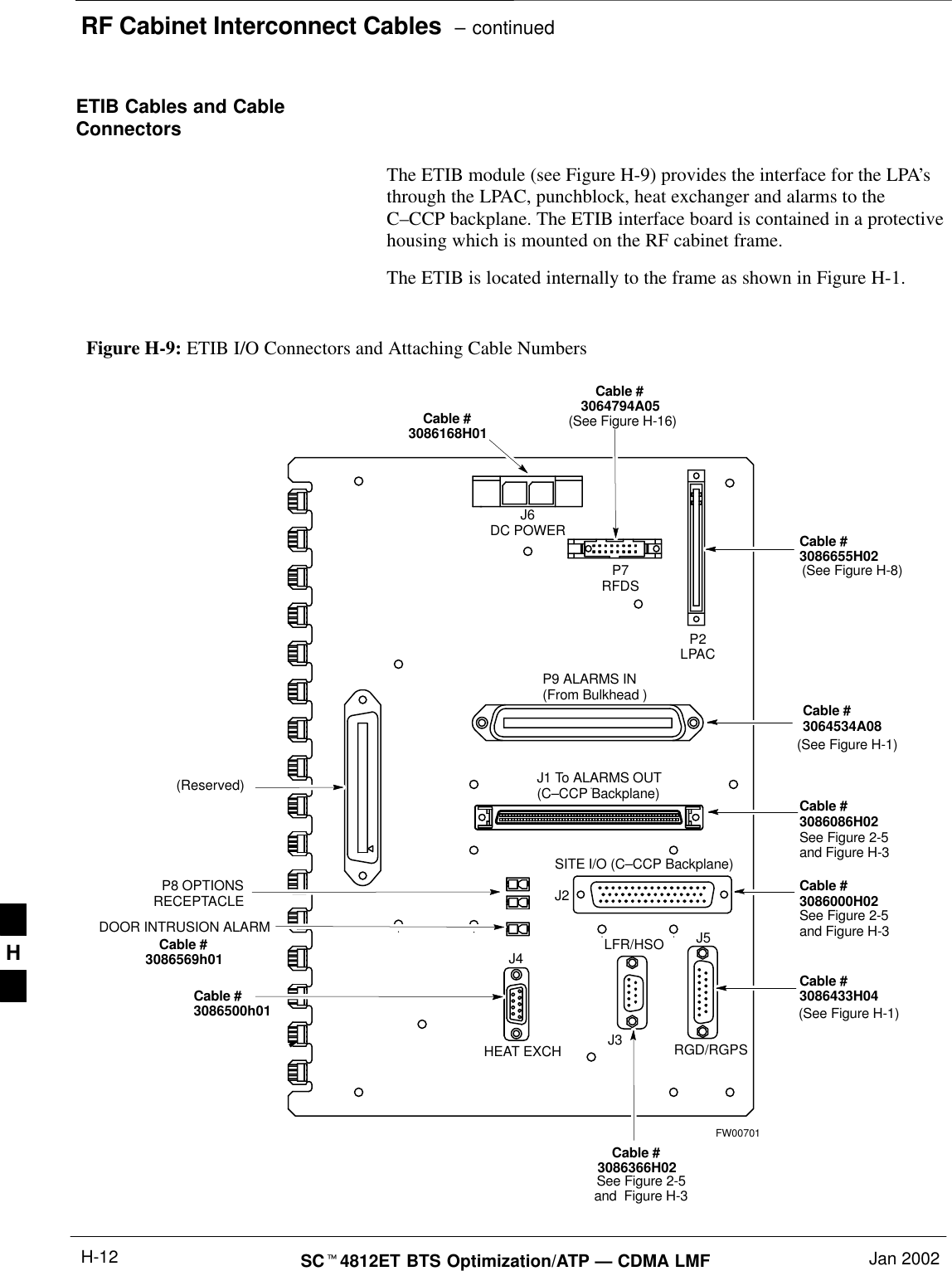
RF Cabinet Interconnect Cables  – continuedSCt4812ET BTS Optimization/ATP — CDMA LMF Jan 2002H-12ETIB Cables and CableConnectors The ETIB module (see Figure H-9) provides the interface for the LPA’sthrough the LPAC, punchblock, heat exchanger and alarms to theC–CCP backplane. The ETIB interface board is contained in a protectivehousing which is mounted on the RF cabinet frame.The ETIB is located internally to the frame as shown in Figure H-1.SITE I/O (C–CCP Backplane)Figure H-9: ETIB I/O Connectors and Attaching Cable NumbersFW00701P7RFDSJ6DC POWER(Reserved) J1 To ALARMS OUT(C–CCP Backplane)P2LPACP9 ALARMS IN(From Bulkhead )RGD/RGPSP8 OPTIONSRECEPTACLECable #3064794A05Cable #3086655H02Cable #3064534A08Cable #3086086H02Cable #3086000H02Cable #3086433H04Cable #3086366H02J2J5LFR/HSOJ3J4HEAT EXCH(See Figure H-16)See Figure 2-5and Figure H-3See Figure 2-5and Figure H-3See Figure 2-5and  Figure H-3Cable #3086500h01(See Figure H-8)(See Figure H-1)(See Figure H-1)Cable #3086168H01Cable #3086569h01DOOR INTRUSION ALARMH
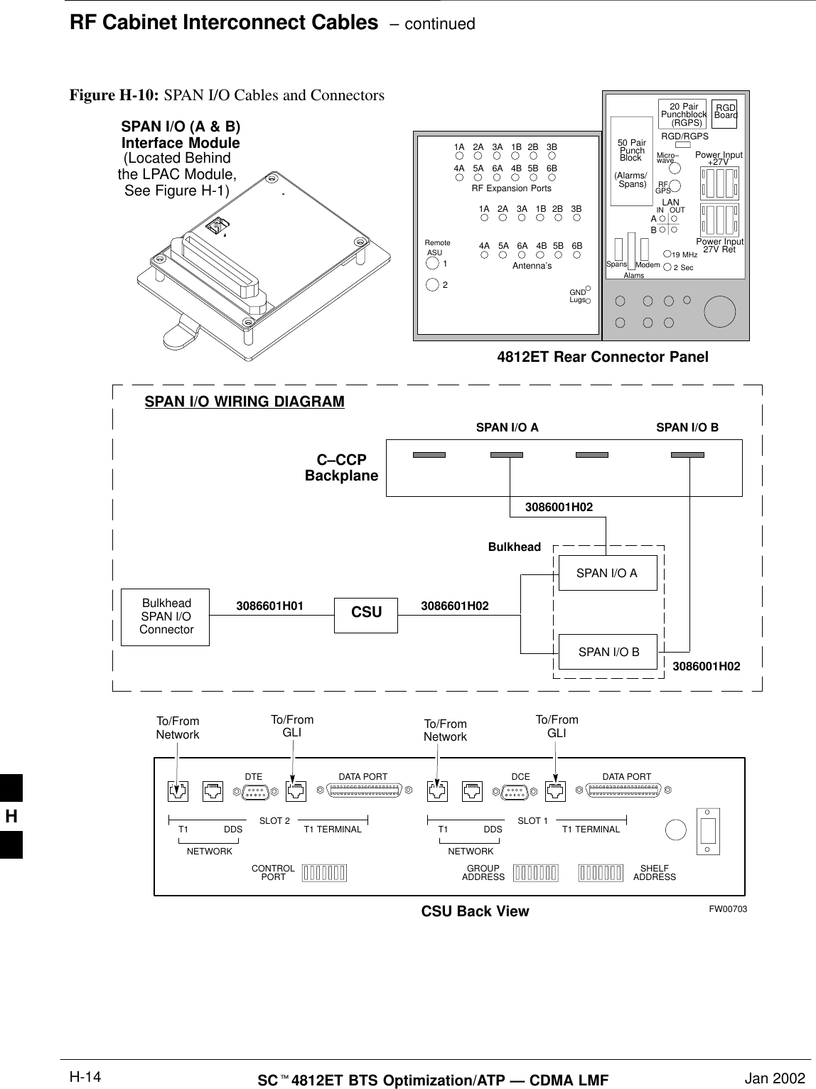
RF Cabinet Interconnect Cables – continuedJan 2002 H-13SCt4812ET BTS Optimization/ATP — CDMA LMFSPAN I/O Cable ConnectionDiagram The SPAN I/O card provides the frame interface and secondary surgeprotection for the T1 lines. There are two span cards in an RF cabinet.SPAN I/O A supports spans A, C, and E. SPAN I/O B supports span B,D, and F. See Figure H-10 for SPAN cables and cable connections.The SPAN I/O is located internally to the frame as shown in Figure H-1. . . . continued on next pageH
RF Cabinet Interconnect Cables  – continuedSCt4812ET BTS Optimization/ATP — CDMA LMF Jan 2002H-14Figure H-10: SPAN I/O Cables and ConnectorsSPAN I/O (A & B)Interface ModuleRF Expansion PortsPunchBlock Power Input27V RetAntenna’s1A 2A 3A 1B 2B 3B4A 5A 6A 4B 5B 6B1A 2A 3A 1B 2B 3B4A 5A 6A 4B 5B 6B12RemoteASUGNDLugs50 Pair(Alarms/Punchblock20 Pair(RGPS)RGDBoardRGD/RGPSPower Input+27VMicro–waveRFGPSABIN OUTLAN19 MHz2 SecSpansAlamsModemSpans)SLOT 1SLOT 2 T1 TERMINAL T1 TERMINALCONTROLPORT GROUPADDRESS SHELFADDRESST1 DDS T1 DDSDTE DCEDATA PORT DATA PORTCSU Back ViewNETWORK NETWORKTo/FromNetworkTo/FromGLI To/FromNetworkTo/FromGLIBulkheadSPAN I/OConnector3086601H01 CSU 3086601H02SPAN I/O BSPAN I/O A3086001H02SPAN I/O WIRING DIAGRAMC–CCPBackplane4812ET Rear Connector Panel(Located Behindthe LPAC Module,See Figure H-1)SPAN I/O A3086001H02SPAN I/O BBulkheadFW00703H
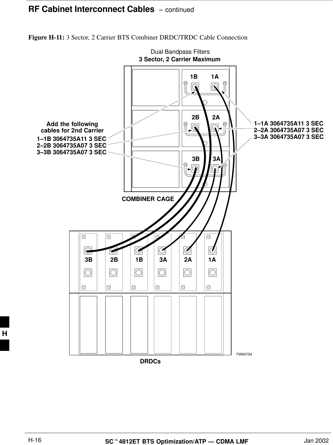
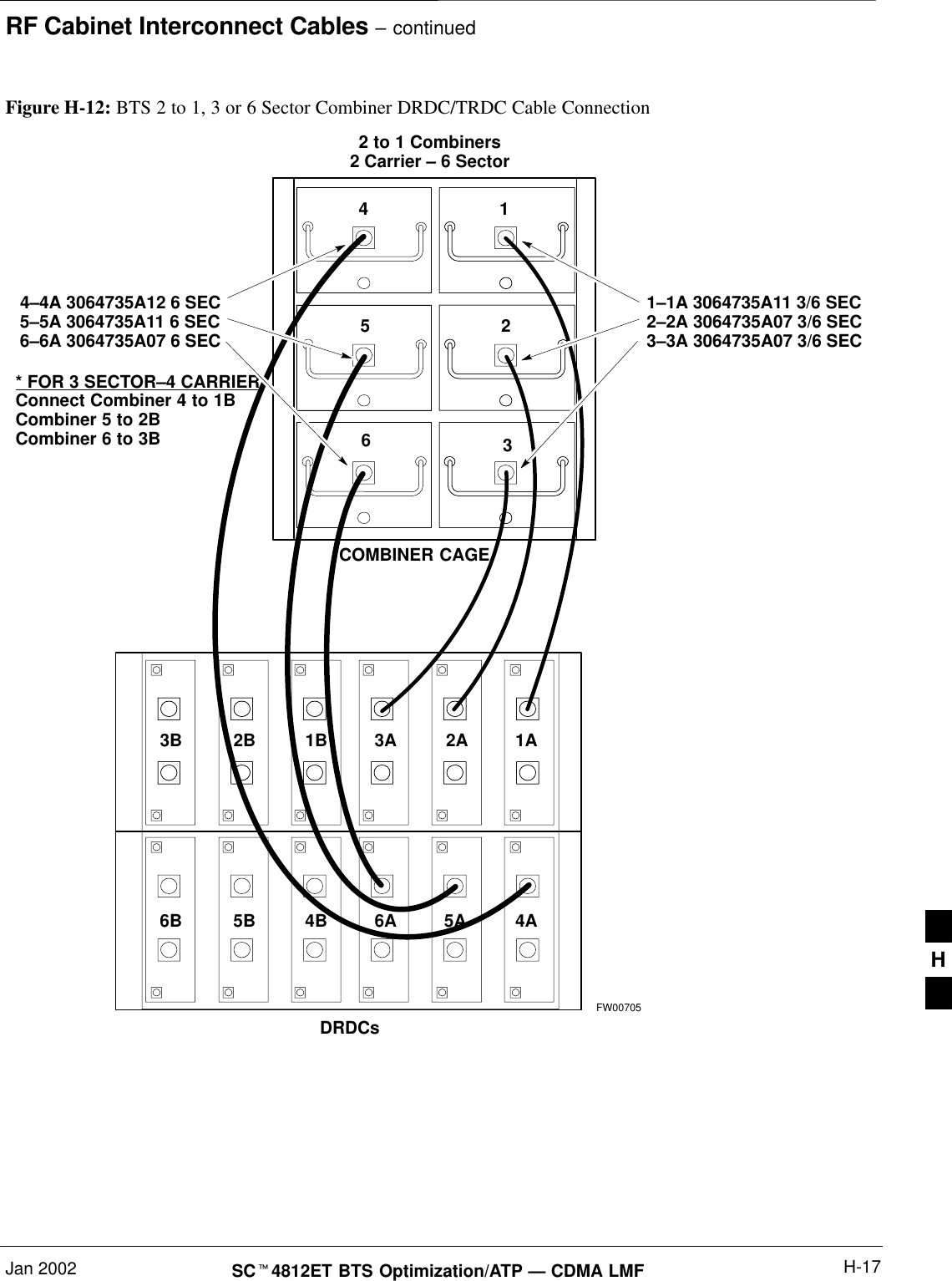
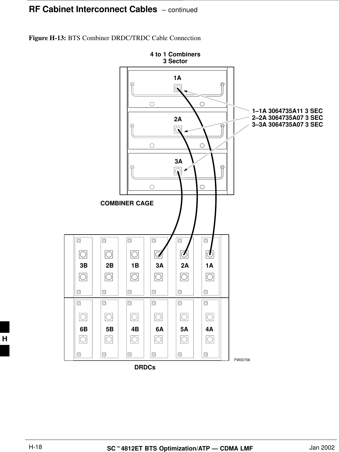
RF Cabinet Interconnect Cables – continuedJan 2002 H-15SCt4812ET BTS Optimization/ATP — CDMA LMFDRDC/TRDC Cables and CableConnections The DRDC is a Duplexer, RX Filter, and Directional Coupler whichprovides the RF interface at the rear of the cabinet. The connections arethe antenna connection (outside rear), transmit into the DRDC TX filter.Receive out of DRDC (RX filter), and Directional coupler.The TRDC is a TX filter/RX filter/Directional Coupler that is the sameas the DRDC except the TRDC has two antenna outputs (TX only andRX only) The TRDC is not available in the 1.9 GHz band.See Figure H-11, Figure H-12, Figure H-13, and Figure H-14 for thecable diagram that fits the configuration of your BTS site. . . . continued on next pageH
RF Cabinet Interconnect Cables  – continuedSCt4812ET BTS Optimization/ATP — CDMA LMF Jan 2002H-16COMBINER CAGEFW00704Figure H-11: 3 Sector, 2 Carrier BTS Combiner DRDC/TRDC Cable Connection1A1B2A2B3A3B1A2A3A1B2B3B3 Sector, 2 Carrier Maximum1–1B 3064735A11 3 SEC2–2B 3064735A07 3 SEC3–3B 3064735A07 3 SEC1–1A 3064735A11 3 SEC2–2A 3064735A07 3 SEC3–3A 3064735A07 3 SECAdd the followingcables for 2nd CarrierDRDCsDual Bandpass FiltersH
RF Cabinet Interconnect Cables – continuedJan 2002 H-17SCt4812ET BTS Optimization/ATP — CDMA LMF* FOR 3 SECTOR–4 CARRIERConnect Combiner 4 to 1BCombiner 5 to 2BCombiner 6 to 3BCOMBINER CAGEFW007051425361A2A3A1B2B3B2 to 1 Combiners2 Carrier – 6 Sector4–4A 3064735A12 6 SEC5–5A 3064735A11 6 SEC6–6A 3064735A07 6 SEC1–1A 3064735A11 3/6 SEC2–2A 3064735A07 3/6 SEC3–3A 3064735A07 3/6 SECDRDCsFigure H-12: BTS 2 to 1, 3 or 6 Sector Combiner DRDC/TRDC Cable Connection4A5A6A4B5B6BH
RF Cabinet Interconnect Cables  – continuedSCt4812ET BTS Optimization/ATP — CDMA LMF Jan 2002H-18FW007061A2A3A1A2A3A1B2B3B4 to 1 Combiners3 Sector1–1A 3064735A11 3 SEC2–2A 3064735A07 3 SEC3–3A 3064735A07 3 SECCOMBINER CAGEDRDCsFigure H-13: BTS Combiner DRDC/TRDC Cable Connection4A5A6A4B5B6BH

Navigation menu