Nokia Solutions and Networks T5JX1 UBS CDMA XMI Transceiver at 800 MHz User Manual Exhibit 8a
Nokia Solutions and Networks UBS CDMA XMI Transceiver at 800 MHz Exhibit 8a
Contents
Exhibit 8a

APPLICANT: MOTOROLA
Cellular Networks
FCC ID: IHET5JX1
Installation Manual Exhibit
UBS CDMA XMI Transceiver at 800MHz
FCC Filing – UBS CDMA XMI Transceiver at 800MHz (cover page)

R20 1X UBS Macro BTS Hardware Installation
68P09283A62 -3 AUG 2007
PRELIMINARY
© 2007 Motorola, Inc. All Rights R eserv ed

Accuracy
While reasonable efforts have been made to assure the accuracy of this document, Motorola, Inc. assumes no
liability resulting from any inaccuracies or omissions in this document, or from use of the information obtained
herein. Motorola, Inc. reserves the right to make changes to any products described herein to improve reliability ,
function, or design, and reserves the right to revise this document and to make changes from time to time in content
hereof with no obligation to notify any person of revisions or changes. Motorola, Inc. does not assume any liability
arising out of the application or use of any product, software, or circuit described herein; neither does it convey
license under its patent rights or the rights of others. It is possible that this publication may contain references to, or
information about Motorola products (machines and programs), programming, or services that are not announced
in your country . Such references or information must not be construed to mean that Motorola intends to announce
such Motorola products, programming, or services in your country .
Copyrights
This document, Motorola products, and 3rd P arty Software products described in this document may include
or describe copyrighted Motorola and other 3rd P arty supplied computer programs stored in semiconductor
memories or other media. Laws in the United States and other countries preserve for Motorola, its licensors, and
other 3rd P arty supplied software certain exclusive rights for copyrighted material, including the exclusive right
to copy , reproduce in any form, distribute and make derivative works of the copyrighted material. Accordingly ,
any copyrighted material of Motorola, its licensors, or the 3rd P arty software supplied material contained in the
Motorola products described in this document may not be copied, reproduced, reverse engineered, distributed,
merged or modified in any manner without the express written permission of Motorola. Furthermore, the purchase
of Motorola products shall not be deemed to grant either directly or by implication, estoppel, or otherwise, any
license under the copyrights, patents or patent applications of Motorola or other 3rd P arty supplied software,
except for the normal non-exclusive, royalty free license to use that arises by operation of law in the sale of a
product.
A list of 3rd P arty supplied software copyrights are contained in the Supplemental information section of this
document.
Restrictions
Software and documentation are copyrighted materials. Making unauthorized copies is prohibited by law . No part
of the software or documentation may be reproduced, transmitted, transcribed, stored in a retrieval system, or
translated into any language or computer language, in any form or by any means, without prior written permission
of Motorola, Inc.
License Agreements
The software described in this document is the property of Motorola, Inc and its licensors. It is furnished by express
license agreement only and may be used only in accordance with the terms of such an agreement.
High Risk Materials
Components, units, or 3rd P arty products used in the product described herein are NOT fault-tolerant and are NOT
designed, manufactured, or intended for use as on-line control equipment in the following hazardous environments
requiring fail-safe controls: the operation of Nuclear F acilities, Aircraft Navigation or Aircraft Communication
Systems, Air Traffic Control, Life Support, or W eapons Systems (High Risk Activities). Motorola and its supplier(s)
specifically disclaim any expressed or implied warranty of fitness for such High Risk Activities.
T rademarks
Motorola and the Stylized M Logo are registered in the US P atent & Trademark Office. All other product or service
names are the property of their respective owners.
The CE mark confirms Motorola, Inc. statement of compliance with EU directives applicable to this product. Copies
of the Declaration of Compliance and installation information in accordance with the requirements of EN50385 can
be obtained from the local Motorola representative or by contacting the Customer Network Resolution Center
(CNRC). The 24 hour telephone numbers are listed at h t t p s : / / m y n e t w o r k s u p p o r t . m o t o r o l a . c o m . Select Customer
Network Resolution Center contact information. Alternatively if you do not have access to CNRC or the
internet, contact the Local Motorola Office.
PRELIMINARY A UG 2007

T a b l e
o f
C o n t e n t s
Contents
■■■■■■■■■■■■■■■■■■■■■■■■■■■■■■■■■■■■■■■■■■■■■■■■■■■■■■■■■■■■■■
■
■
■
■
R20 1X UBS Macro BTS Hardware Installation
Revision history ......................................... 3
Version information ..................................... 3
Resolution of Service Requests . . . . . . . . . . . . . . . . . . . . . . . . . . . . . . . 3
Incorporation of Change Notices . . . . . . . . . . . . . . . . . . . . . . . . . . . . . . . 3
General information ....................................... 4
Purpose ........................................... 4
Cross references ....................................... 4
Text conventions ....................................... 5
Contacting Motorola ....................................... 6
24–hour support ....................................... 6
Questions and comments .................................. 6
Errors ............................................ 6
Security advice .......................................... 7
W arnings, cautions, and notes . . . . . . . . . . . . . . . . . . . . . . . . . . . . . . . . . . 8
W arnings ........................................... 8
Cautions ........................................... 8
Notes ............................................ 8
Safety .............................................. 9
General safety ........................................ 9
Electromagnetic energy ................................... 9
Caring for the environment . . . . . . . . . . . . . . . . . . . . . . . . . . . . . . . . . . . 10
In EU countries ....................................... 10
In non -EU countries ..................................... 10
CMM labeling and disclosure table . . . . . . . . . . . . . . . . . . . . . . . . . . . . . . . 11
Motorola document set ..................................... 12
Ordering documents and CD -ROMs . . . . . . . . . . . . . . . . . . . . . . . . . . . . . 12
Document banner definitions . . . . . . . . . . . . . . . . . . . . . . . . . . . . . . . . 12
Data encryption ....................................... 12
Third P arty Computer Software and Trademarks . . . . . . . . . . . . . . . . . . . . . . . . 13
Computer Software ..................................... 13
Trademarks ......................................... 13
Chapter 1: Introduction and Frame Identication
Abbreviations and Acronyms . . . . . . . . . . . . . . . . . . . . . . . . . . . . . . . . . . . 1 - 2
Abbreviations and Acronyms . . . . . . . . . . . . . . . . . . . . . . . . . . . . . . . . . 1 - 2
Overview ............................................. 1 - 5
Scope of manual ....................................... 1 - 5
Prerequisites ......................................... 1 - 5
Chapter 1 - Introduction and frame identification . . . . . . . . . . . . . . . . . . . . . . 1 - 5
Chapter 2 – UBS Macro BTS installation procedure . . . . . . . . . . . . . . . . . . . . . 1 - 6
Chapter 3 - Low -to -Mid Capacity Frame Expansion Procedures . . . . . . . . . . . . . . . 1 - 6
68P09283A62 -3 i
A UG 2007 PRELIMINARY
Contents
Chapter 4 -What’s next ................................... 1 - 6
Equipment shipped assembled . . . . . . . . . . . . . . . . . . . . . . . . . . . . . . . . 1 - 6
Equipment shipped un -assembled . . . . . . . . . . . . . . . . . . . . . . . . . . . . . . 1 - 6
Follow the task sequence .................................. 1 - 7
Follow the site plan ..................................... 1 - 7
Site cleanliness ....................................... 1 - 7
Site manager ......................................... 1 - 7
Color coding ......................................... 1 - 7
R ack vs. frame ....................................... 1 - 8
Required documentation ................................... 1 - 8
Equipment may vary from figures . . . . . . . . . . . . . . . . . . . . . . . . . . . . . . 1 - 8
Item identification ........................................ 1 - 9
UBS Macro BTS frames ................................... 1 - 9
Items to be installed ..................................... 1 - 15
Tools and materials ....................................... 1 - 16
Required tools and materials . . . . . . . . . . . . . . . . . . . . . . . . . . . . . . . . . 1 - 16
Recommended tools ..................................... 1 - 17
Unpacking Instructions ..................................... 1 - 18
Unpacking the carrier strip assembly . . . . . . . . . . . . . . . . . . . . . . . . . . . . 1 - 18
Unpacking accessory equipment . . . . . . . . . . . . . . . . . . . . . . . . . . . . . . . 1 - 20
Chapter 2: UBS Macro BTS Installation Procedure
Overview ............................................. 2 - 2
Introduction ......................................... 2 - 2
Structural engineer ..................................... 2 - 2
Required items ........................................ 2 - 2
Cabling and configuration options . . . . . . . . . . . . . . . . . . . . . . . . . . . . . . 2 - 2
Color coding ......................................... 2 - 2
Cable list, diagrams and connectors . . . . . . . . . . . . . . . . . . . . . . . . . . . . . . . 2 - 4
Overview ........................................... 2 - 4
UBS Macro BTS external I/O cable run list . . . . . . . . . . . . . . . . . . . . . . . . . 2 - 4
Connector locations ..................................... 2 - 6
Full installation sequence . . . . . . . . . . . . . . . . . . . . . . . . . . . . . . . . . . . . 2 - 11
Overview ........................................... 2 - 11
Prerequisites ......................................... 2 - 11
V erifying site and equipment . . . . . . . . . . . . . . . . . . . . . . . . . . . . . . . . . 2 - 11
Physical installation ..................................... 2 - 11
Site verification ......................................... 2 - 15
Site installation checks . . . . . . . . . . . . . . . . . . . . . . . . . . . . . . . . . . . 2 - 15
Temperature range ..................................... 2 - 16
Frame physical dimensions . . . . . . . . . . . . . . . . . . . . . . . . . . . . . . . . . 2 - 16
Frame clearances ...................................... 2 - 16
Frame DC input power and power cabling information . . . . . . . . . . . . . . . . . . . 2 - 17
Frame positioning ...................................... 2 - 18
R ack base description and dimensions . . . . . . . . . . . . . . . . . . . . . . . . . . . . 2 - 18
T ask 1: Installing RGPS Head . . . . . . . . . . . . . . . . . . . . . . . . . . . . . . . . . . 2 - 20
Objective ........................................... 2 - 20
RGPS head installation .................................... 2 - 20
T asks 2 -3: Installing R ack & Ground Cable . . . . . . . . . . . . . . . . . . . . . . . . . . . 2 - 28
Objectives .......................................... 2 - 28
R ack requirements ...................................... 2 - 28
Structural engineer prerequisite . . . . . . . . . . . . . . . . . . . . . . . . . . . . . . . 2 - 28
Required items ........................................ 2 - 29
Location of rack earth ground terminals . . . . . . . . . . . . . . . . . . . . . . . . . . . 2 - 30
Procedure .......................................... 2 - 30
T ask 4: R ack Mounting the Optional PSM Shelf . . . . . . . . . . . . . . . . . . . . . . . . . 2 - 32
Objectives .......................................... 2 - 32
ii 68P09283A62 -3
PRELIMINARY A UG 2007
R20 1X UBS Macro B T S Hardw are Installation Contents
Required items ........................................ 2 - 32
Procedure .......................................... 2 - 32
Procedural reference diagrams . . . . . . . . . . . . . . . . . . . . . . . . . . . . . . . 2 - 34
T ask 5: R ack Mounting for Low -Capacity Frame . . . . . . . . . . . . . . . . . . . . . . . . . 2 - 36
Objective ........................................... 2 - 36
Required items ........................................ 2 - 36
Procedure .......................................... 2 - 37
Procedural reference diagrams . . . . . . . . . . . . . . . . . . . . . . . . . . . . . . . 2 - 38
T ask 6: Expanding the Low -capacity Frame . . . . . . . . . . . . . . . . . . . . . . . . . . . 2 - 42
Objective ........................................... 2 - 42
Procedure .......................................... 2 - 42
T ask 7: Cabling the Optional PSM Shelf . . . . . . . . . . . . . . . . . . . . . . . . . . . . . 2 - 43
Objectives .......................................... 2 - 43
Required items ........................................ 2 - 43
Procedure .......................................... 2 - 43
T asks 8 -9: Connecting TX/RX Antennas . . . . . . . . . . . . . . . . . . . . . . . . . . . . . 2 - 44
Objectives .......................................... 2 - 44
Required items ........................................ 2 - 44
Location of antenna connectors . . . . . . . . . . . . . . . . . . . . . . . . . . . . . . . 2 - 44
Procedure .......................................... 2 - 44
T asks 10 -13: Connecting RGPS , Spans, Customer Alarms . . . . . . . . . . . . . . . . . . . . 2 - 46
Objectives .......................................... 2 - 46
Cabling options ....................................... 2 - 46
Required items ........................................ 2 - 47
Location of cables AA, W and X . . . . . . . . . . . . . . . . . . . . . . . . . . . . . . . 2 - 47
Balanced T1/E1 cable (W) details . . . . . . . . . . . . . . . . . . . . . . . . . . . . . . 2 - 47
Customer alarm input/output (IP/OP) cable (X) details . . . . . . . . . . . . . . . . . . . . 2 - 49
T ask 14: Connecting +27 V DC P ower . . . . . . . . . . . . . . . . . . . . . . . . . . . . . . 2 - 55
Objectives .......................................... 2 - 55
Frame power cables and connector information . . . . . . . . . . . . . . . . . . . . . . . 2 - 55
Required items ........................................ 2 - 56
P ower cabling and tie down requirements . . . . . . . . . . . . . . . . . . . . . . . . . . 2 - 57
Contact/lug, DC connector housing and PDU input power . . . . . . . . . . . . . . . . . . 2 - 57
Procedure .......................................... 2 - 58
T ask 15: Connecting -48 V DC P ower . . . . . . . . . . . . . . . . . . . . . . . . . . . . . . 2 - 60
Objectives .......................................... 2 - 60
Frame power cables and connector information . . . . . . . . . . . . . . . . . . . . . . . 2 - 60
Required items ........................................ 2 - 61
P ower cabling and tie down requirements . . . . . . . . . . . . . . . . . . . . . . . . . . 2 - 62
Contact/lug, DC connector housing and PDU input power . . . . . . . . . . . . . . . . . . 2 - 62
Procedure .......................................... 2 - 63
T ask 16: Connecting 220 V AC P ower . . . . . . . . . . . . . . . . . . . . . . . . . . . . . . 2 - 65
Objectives .......................................... 2 - 65
Frame AC power cables and wiring information . . . . . . . . . . . . . . . . . . . . . . . 2 - 65
Required items ........................................ 2 - 66
AC PSM shelf AC power input detail . . . . . . . . . . . . . . . . . . . . . . . . . . . . . 2 - 66
Procedure .......................................... 2 - 68
Chapter 3: Low -to -Mid Capacity Frame Expansion Procedures
Low -to -Mid Capacity Frame Expansion Overview . . . . . . . . . . . . . . . . . . . . . . . . 3 - 2
How to use this chapter ................................... 3 - 2
Adding Circuit Breakers/Connectors to PDU . . . . . . . . . . . . . . . . . . . . . . . . . . . 3 - 3
Objective ........................................... 3 - 3
Required items ........................................ 3 - 3
Procedure .......................................... 3 - 4
Procedural reference diagram . . . . . . . . . . . . . . . . . . . . . . . . . . . . . . . . 3 - 6
Adding an XMI .......................................... 3 - 7
68P09283A62 -3 iii
A UG 2007 PRELIMINARY
Contents
Objective ........................................... 3 - 7
Required items ........................................ 3 - 7
Procedure .......................................... 3 - 8
Procedural reference diagram . . . . . . . . . . . . . . . . . . . . . . . . . . . . . . . . 3 - 9
Adding a DMI .......................................... 3 - 11
Objective ........................................... 3 - 11
Required items ........................................ 3 - 11
Prerequisite ......................................... 3 - 12
Procedure .......................................... 3 - 12
Procedural reference diagram . . . . . . . . . . . . . . . . . . . . . . . . . . . . . . . . 3 - 14
Adding a Second Set of IDRFs . . . . . . . . . . . . . . . . . . . . . . . . . . . . . . . . . . 3 - 15
Objective ........................................... 3 - 15
Required items ........................................ 3 - 15
Procedure .......................................... 3 - 16
Procedural reference diagram . . . . . . . . . . . . . . . . . . . . . . . . . . . . . . . . 3 - 17
Adding an Optional RX Splitter . . . . . . . . . . . . . . . . . . . . . . . . . . . . . . . . . 3 - 18
Objective ........................................... 3 - 18
Required items ........................................ 3 - 18
Procedure .......................................... 3 - 18
Procedural reference diagram . . . . . . . . . . . . . . . . . . . . . . . . . . . . . . . . 3 - 19
Adding a third PSM (–48 V or 220 V AC only) . . . . . . . . . . . . . . . . . . . . . . . . . . 3 - 20
Objective ........................................... 3 - 20
Required items ........................................ 3 - 20
Procedure .......................................... 3 - 21
Mid -capacity Expansion Interconnect Cabling . . . . . . . . . . . . . . . . . . . . . . . . . . 3 - 22
Objective ........................................... 3 - 22
Installing DC power cables . . . . . . . . . . . . . . . . . . . . . . . . . . . . . . . . . . 3 - 22
Installing/Connecting RF cables (XMI to IDRF) . . . . . . . . . . . . . . . . . . . . . . . 3 - 25
Installing XMI to DMI cables . . . . . . . . . . . . . . . . . . . . . . . . . . . . . . . . . 3 - 28
Installing DMI to S SI cables . . . . . . . . . . . . . . . . . . . . . . . . . . . . . . . . . 3 - 29
Installing RX splitter to XMI RX RF cables or RX share cable . . . . . . . . . . . . . . . . 3 - 30
Chapter 4: What’s Next
Installation completion ...................................... 4 - 2
Clean up the site ....................................... 4 - 2
Fill out the installation completion checklist . . . . . . . . . . . . . . . . . . . . . . . . . 4 - 3
Record “ As -Built” information . . . . . . . . . . . . . . . . . . . . . . . . . . . . . . . . 4 - 4
Performing the ATP s..................................... 4 - 4
Loading the software .................................... 4 - 4
iv 68P09283A62 -3
PRELIMINARY A UG 2007

L i s t
o f
F i g u r e s
List of Figures
■■■■■■■■■■■■■■■■■■■■■■■■■■■■■■■■■■■■■■■■■■■■■■■■■■■■■■■■■■■■■■
■
■
■
■
Figure 1 -1: UBS Macro BTS low -tier/low -capacity frame (1000 mm rack) . . . . . . . . . . . . 1 - 10
Figure 1 -2: Low capacity UBS Macro BTS starter frame (1800 mm rack) . . . . . . . . . . . . 1 - 11
Figure 1 -3: UBS Macro BTS mid -capacity frame (1800 mm rack) . . . . . . . . . . . . . . . . 1 - 12
Figure 1 -4: High capacity 800 MHz UBS Macro BTS fully expanded frame (1800 mm rack) . . . 1 - 13
Figure 1 -5: High -capacity 1.9 GHz UBS Macro BTS fully expanded frame (1800 mm rack) . . . 1 - 14
Figure 1 -6: Items to install . . . . . . . . . . . . . . . . . . . . . . . . . . . . . . . . . . . . 1 - 15
Figure 1 -7: Carrier strip assembly with inner carton support . . . . . . . . . . . . . . . . . . 1 - 19
Figure 1 -8: Carrier strip assembly with inner carton support removed . . . . . . . . . . . . . 1 - 19
Figure 2 -1: 800 MHz IDRF I/O connectors . . . . . . . . . . . . . . . . . . . . . . . . . . . . 2 - 7
Figure 2 -2: 1.9 GHz IDRF I/O connectors . . . . . . . . . . . . . . . . . . . . . . . . . . . . 2 - 7
Figure 2 -3: S SI front panel connectors . . . . . . . . . . . . . . . . . . . . . . . . . . . . . . 2 - 9
Figure 2 -4: PSM shelf front panel connectors . . . . . . . . . . . . . . . . . . . . . . . . . . 2 - 10
Figure 2 -5: R ack footprint . . . . . . . . . . . . . . . . . . . . . . . . . . . . . . . . . . . . 2 - 19
Figure 2 -6: RGPS cabling diagram . . . . . . . . . . . . . . . . . . . . . . . . . . . . . . . . 2 - 21
Figure 2-7: RGPS wiring ..................................... 2 - 22
Figure 2 -8: RGPS lightning arrestor wiring . . . . . . . . . . . . . . . . . . . . . . . . . . . 2 - 23
Figure 2-9: RGPS heads ..................................... 2 - 24
Figure 2 -10: Installing the RGPS head . . . . . . . . . . . . . . . . . . . . . . . . . . . . . . 2 - 25
Figure 2 -11: Connector pin numbering for cables NN and AA . . . . . . . . . . . . . . . . . . 2 - 26
Figure 2 -12: Location of ground terminals on a Motorola rack . . . . . . . . . . . . . . . . . . 2 - 30
Figure 2 -13: Hanger screw layout for the optional PSM shelf . . . . . . . . . . . . . . . . . . 2 - 34
Figure 2 -14: Hanging the PSM shelf . . . . . . . . . . . . . . . . . . . . . . . . . . . . . . . 2 - 35
Figure 2 -15: Hanger screw layout for UBS Macro carrier strip assembly . . . . . . . . . . . . 2 - 39
Figure 2 -16: Lifting and hanging the carrier strip assembly on the rack . . . . . . . . . . . . . 2 - 40
Figure 2 -17: Carrier strip assembly keyhole screw locations . . . . . . . . . . . . . . . . . . 2 - 41
Figure 2 -18: T1/E1 balanced span line cable (W) pin numbering . . . . . . . . . . . . . . . . . 2 - 47
Figure 2 -19: Customer alarm cable (X) pin numbering . . . . . . . . . . . . . . . . . . . . . . 2 - 51
Figure 2 -20: +27 V DC power input cable (DC) wire tie -wrap example . . . . . . . . . . . . . 2 - 57
Figure 2 -21: +27 V DC power input cable (DC) connector and connection to PDU . . . . . . . . 2 - 58
Figure 2 -22: 48 V DC power input cable (CC) wire tie -wrap example . . . . . . . . . . . . . . 2 - 62
Figure 2 -23: 48 V DC power input cable (CC) connector and connection to PSM shelf . . . . . . 2 - 63
Figure 2 -24: AC PSM shelf AC power input terminal block and wiring details . . . . . . . . . . 2 - 67
Figure 3 -1: Adding a Breaker Assembly Module to the PDU . . . . . . . . . . . . . . . . . . . 3 - 6
Figure 3 -2: Installing a 2nd XMI . . . . . . . . . . . . . . . . . . . . . . . . . . . . . . . . . 3 - 10
Figure 3 -3: Installing a 2nd DMI . . . . . . . . . . . . . . . . . . . . . . . . . . . . . . . . . 3 - 14
Figure 3 -4: Installing the second set of IDRFs . . . . . . . . . . . . . . . . . . . . . . . . . . 3 - 17
Figure 3 -5: Mounting the RX splitter . . . . . . . . . . . . . . . . . . . . . . . . . . . . . . 3 - 19
68P09283A62 -3 v
A UG 2007 PRELIMINARY

L i s t
o f
T a b l e s
List of Tables■■■■■■■■■■■■■■■■■■■■■■■■■■■■■■■■■■■■■■■■■■■■■■■■■■■■■■■■■■■■■■
■
■
■
■
T able 1: Manual version history . . . . . . . . . . . . . . . . . . . . . . . . . . . . . . . . . 3
T able 1 -1: Abbreviations and Acronyms . . . . . . . . . . . . . . . . . . . . . . . . . . . . . 1 - 2
T able 2 -1: Color code – DC power connectors/cables . . . . . . . . . . . . . . . . . . . . . . 2 - 3
T able 2 -2: Color code - RF Equipment and Connectors/Cables . . . . . . . . . . . . . . . . . . 2 - 3
T able 2 -3: UBS Macro BTS external I/O cable run list . . . . . . . . . . . . . . . . . . . . . . 2 - 4
T able 2 -4: Frame dimensions . . . . . . . . . . . . . . . . . . . . . . . . . . . . . . . . . . 2 - 16
T able 2 -5: Minimum frame clearances for airflow . . . . . . . . . . . . . . . . . . . . . . . . 2 - 16
T able 2 -6: Minimum frame clearances for maintenance - front access only . . . . . . . . . . . 2 - 16
T able 2 -7: Minimum frame clearances for maintenance - front and rear access . . . . . . . . . 2 - 17
T able 2 -8: +27 V DC and –48 V DC Frame P ower Cabling and P ower Supply Breaker
Information ........................................... 2 - 17
T able 2 -9: List of required cables for RGPS head installation . . . . . . . . . . . . . . . . . . 2 - 20
T able 2 -10: Pinout for cables NN and AA . . . . . . . . . . . . . . . . . . . . . . . . . . . . 2 - 26
T able 2 -11: T1/E1 I/O cable W (span) signal and pin information . . . . . . . . . . . . . . . . 2 - 48
T able 2 -12: Customer alarm cable (X) pinout for customer IP 1 -12 OP 1 -4 . . . . . . . . . . . . 2 - 51
T able 2 -13: Customer alarm cable (X) pinout for customer IP 13 -24 OP 5 -8 . . . . . . . . . . . 2 - 52
T able 2 -14: +27 V DC connector (Orange) parts information . . . . . . . . . . . . . . . . . . 2 - 55
T able 2 -15: –48 V DC connector (Blue) parts information . . . . . . . . . . . . . . . . . . . . 2 - 61
T able 4 -1: Installation completion checklist . . . . . . . . . . . . . . . . . . . . . . . . . . . 4 - 3
68P09283A62 -3 vii
A UG 2007 PRELIMINARY

A b o u t
T h i s
M a n u a l
R20 1X UBS Macro BTS Hardware
Installation
■■■■■■■■■■■■■■■■■■■■■■■■■■■■■■■■■■■■■■■■■■■■■■■■■■■■■■■■■■■■■■
■
■
■
■
The R20 UBS Macro BTS supports single band 800 MHz or 1.9 GHz RF band, up to
two XMIs, up to two DMIs and one S SI. UBS Macro BTS frame configurations with up
to four XMIs and up to five DMIs will be available in the future.
What is covered in this manual?
The UBS Macro BTS Hardware Installation manual describes the installation of Motorola
supported configurations of the UBS Macro BTS system. The UBS Macro BTS system supports
either the 800 MHz or the 1.9 GHz RF band and IP -packet backhaul. In addition, CDMA 1X and
CDMA EV -DO channels are supported as well as Open Transport Interface (OTI) for IP -packet
backhaul via Ethernet. The UBS Macro BTS frame can also be configured for +27 V DC
operation, optional -48 V DC or optional 220 V AC operation.
The UBS Macro BTS air interface supports the following:
•Omni or 3–sector antenna configurations
•Single RF band operation only; 800 MHz or 1.9 GHz RF band
•Up to 120 W of total TX RF power output and up to 30 W TX RF power output per carrier
•Dual path, Main and Diversity , RX antennas
UBS Macro BTS frames are also configured for low , mid, or high capacity . Capacity is determined
by the quantity of sector carriers and traffic channels supported by the frame. The quantity of
sector carriers is a function of the quantity of XMIs. The quantity of traffic channels is a function
of the quantity of modems. Because the modems are inside the DMI, the quantity of DMIs is a
capacity factor . The capacity of a UBS Macro BTS frame is essentially based on the following:
•low capacity - one XMI and up to two DMIs
•mid capacity - two XMIs and two DMIs
•high capacity - more than two XMIs (four XMIs maximum) and more than two DMIs (five
DMIs maximum)
68P09283A62 -3 1
A UG 2007 PRELIMINARY

F or Software Release 2.20.x, only low and mid capacity frames are available/supported.
High capacity UBS Macro BTS frames will be available in the future.
The manual covers the following topics:
•Chapter 1 provides a brief description of the information presented in the manual, frame
identification information, installation sequence, and a list of tools.
•Chapter 2 provides illustrations displaying the location of all UBS Macro connectors for
external cabling and wiring purposes, external cable run list, and a detailed installation
sequence. Installation procedures cover mounting items to the rack and installing the
external cabling.
•Chapter 3 provides information and procedures needed for expanding the low -capacity
UBS Macro BTS starter/expansion frame to the mid -capacity frame configuration.
•Chapter 4 provides procedures for cleaning up the site and the installation completion
checklist.
2 68P09283A62 -3
PRELIMINARY A UG 2007

R evision history
Revision history■■■■■■■■■■■■■■■■■■■■■■■■■■■■■■■■■■■■■■■■■■■■■■■■■■■■■■■■■■■■■■
■
■
The following shows the issue status of this manual since it was first released.
Version information
Table 1 Manual v ersion history
Manual
issue
Date of issue
Remarks
1 JUN 15, 2007
DRAFT version for SME review
2 AUG 10, 2007
PRELIMINAR Y version for
SME review . Does not include
E -GPS and the special recently
requested SPRINT mechanics.
3 AUG 31, 2007
PRELIMINAR Y version for
Deployment. Does not include
E -GPS and the special recently
requested SPRINT mechanics.
Resolution of Service Requests
The following Service Requests are resolved in this document:
Service Request CMBP Number
Remarks
NA NA NA
Incorporation of Change Notices
The following Change Notices (CN) are incorporated in this document:
CN Date CN Number
T itle
NA NA NA
68P09283A62 -3 3
A UG 2007 PRELIMINARY

Gener al information
General information
■■■■■■■■■■■■■■■■■■■■■■■■■■■■■■■■■■■■■■■■■■■■■■■■■■■■■■■■■■■■■■
■
■
Purpose
Motorola cellular communications documents are intended to instruct and assist personnel in
the operation, installation and maintenance of the Motorola cellular infrastructure equipment
and ancillary devices. It is recommended that all personnel engaged in such activities be
properly trained by Motorola.
Motorola disclaims all liability whatsoever , implied or express, for any risk of damage, loss or
reduction in system performance arising directly or indirectly out of the failure of the customer ,
or anyone acting on the customer’s behalf , to abide by the instructions, system parameters,
or recommendations made in this document.
These documents are not intended to replace the system and equipment training offered by
Motorola. They can be used to supplement and enhance the knowledge gained through such
training.
If this document was obtained when attending a Motorola training course, it will
not be updated or amended by Motorola. It is intended for TRAINING P URPOSES
ONL Y . If it was supplied under normal operational circumstances, to support a major
software release, then corrections are supplied automatically by Motorola and posted
on the Motorola customer website.
Cross references
References made to external publications are shown in italics. Other cross references,
emphasized in blue text in electronic versions, are active links to the references.
This document is divided into numbered chapters that are divided into sections. Sections are
not numbered, but are individually named at the top of each page, and are listed in the table of
contents.
4 68P09283A62 -3
PRELIMINARY A UG 2007

Gener al information
Text conventions
The following conventions are used in the Motorola cellular infrastructure documents to
represent keyboard input text, screen output text, and special key sequences.
Input
Characters typed in at the keyboard are shown like this.
Items of interest within a command appear like this.
Output
Messages, prompts, file listings, directories, utilities, and environmental
variables that appear on the screen are shown like this.
Items of interest within a screen display appear like this.
Special key sequences
Special key sequences are represented as follows:
CTRL-c or CTRL+C
Press the Ctrl and Ckeys at the same time.
CTRL-SHIFT-c or
CTRL+SHIFT+C
Press the Ctrl ,Shift , and Ckeys at the same time.
ALT-f or ALT+F
Press the Alt and Fkeys at the same time.
ALT+SHIFT+F11
Press the Alt ,Shift and F11 keys at the same time.
¦Press the pipe symbol key .
RETURN or ENTER
Press the Return or Enter key .
68P09283A62 -3 5
A UG 2007 PRELIMINARY
Contacting Motorola
Contacting Motorola■■■■■■■■■■■■■■■■■■■■■■■■■■■■■■■■■■■■■■■■■■■■■■■■■■■■■■■■■■■■■■
■
■
Motorola appreciates feedback from the users of our documents.
24–hour support
If you have problems regarding the operation of your equipment, contact the Customer Network
Resolution Center (CNRC) for immediate assistance. The 24–hour telephone numbers are listed
at https://mynetworksupport.motorola.com . Select Customer Network Resolution Center
contact information . Alternatively if you do not have access to CNRC or the internet, contact
the Local Motorola Office.
Questions and comments
Send questions and comments regarding user documentation to the email address:
mydocs@motorola.com .
Errors
T o report a documentation error , call the CNRC (Customer Network Resolution Center) and
provide the following information to enable CNRC to open an SR (Service Request):
•The document type
•The document title, part number , and revision character
•The page number with the error
•A detailed description of the error and if possible the proposed solution
6 68P09283A62 -3
PRELIMINARY A UG 2007
Securit y advice
Security advice■■■■■■■■■■■■■■■■■■■■■■■■■■■■■■■■■■■■■■■■■■■■■■■■■■■■■■■■■■■■■■
■
■
Motorola systems and equipment provide security parameters that can be configured by the
operator based on their particular operating environment. Motorola recommends setting and
using these parameters following industry recognized security practices. Security aspects
to be considered are protecting the confidentiality , integrity , and availability of information
and assets. Assets include the ability to communicate, information about the nature of the
communications, and information about the parties involved.
In certain instances, Motorola makes specific recommendations regarding security practices.
The implementation of these recommendations and final responsibility for the security of the
system lies with the operator of the system.
Contact the Customer Network Resolution Center (CNRC) for assistance. The 24–hour
telephone numbers are listed at https://mynetworksupport.motorola.com . Select Customer
Network Resolution Center contact information , from the menu located to the left of the
Login box. Alternatively if you do not have access to CNRC or the internet, contact the Local
Motorola Office.
68P09283A62 -3 7
A UG 2007 PRELIMINARY

W arnings, cautions, and notes
Warnings, cautions, and notes■■■■■■■■■■■■■■■■■■■■■■■■■■■■■■■■■■■■■■■■■■■■■■■■■■■■■■■■■■■■■■
■
■
The following describes how warnings and cautions are used in this document and in all
documents of this Motorola document set.
Warnings
W arnings precede instructions that contain potentially hazardous situations. W arnings are
used to alert the reader to possible hazards that could cause loss of life or physical injury . A
warning has the following format:
W arning text and consequence for not following the instructions in the w arning.
Cautions
Cautions precede instructions and are used when there is a possibility of damage to systems,
software, or individual items of equipment within a system. However , this damage presents
no danger to personnel. A caution has the following format:
Caution text and consequence for not following the instructions in the caution.
Notes
A note means that there is a possibility of an undesirable situation or provides additional
information to help the reader understand a topic or concept. A note has the following format:
Note text.
8 68P09283A62 -3
PRELIMINARY A UG 2007

Safet y
Safety
■■■■■■■■■■■■■■■■■■■■■■■■■■■■■■■■■■■■■■■■■■■■■■■■■■■■■■■■■■■■■■
■
■
General safety
The following general safety guidelines apply to Motorola equipment:
•The power jack and mating plug of the power cable must meet International
Electrotechnical Commission (IEC) safety standards.
Refer to
Grounding Guideline for Cellular R adio Installations – 68P81150E62
.
•P ower down or unplug the equipment before servicing.
•Using non -Motorola parts for repair could damage the equipment or void warranty .
Contact Motorola W arranty and Repair for service and repair instructions.
•P ortions of Motorola equipment may be damaged from exposure to electrostatic discharge.
Use precautions to prevent damage.
Electromagnetic energy
Relevant standards (USA and EC) applicable when working with RF equipment are:
•
ANSI IEEE C95.1 -1991, IEEE Standard for Safety Levels with Respect to Human Exposure
to R adio Frequency Electromagnetic Fields, 3 kHz to 300 GHz.
•Council recommendation of 12 July 1999 on the limitation of exposure of the general
public to electromagnetic fields (0 Hz to 300 GHz) (1999/519/EC) and respective national
regulations.
•
Directive 2004/40/EC of the European P arliament and of the Council of 29 April 200
4 on
the minimum health and safety requirements regarding the exposure of workers to the
risks arising from physical agents (electromagnetic fields) (18th individual Directive within
the meaning of Article 16(1) of Directive 89/391/EEC).
68P09283A62 -3 9
A UG 2007 PRELIMINARY

Caring for the en vironment
Caring for the environment■■■■■■■■■■■■■■■■■■■■■■■■■■■■■■■■■■■■■■■■■■■■■■■■■■■■■■■■■■■■■■
■
■
The following information describes national or regional requirements for the disposal of
Motorola supplied equipment and for the approved disposal of surplus packaging.
Contact the Customer Network Resolution Center (CNRC) for assistance. The 24–hour
telephone numbers are listed at https://mynetworksupport.motorola.com . Select Customer
Network Resolution Center contact information . Alternatively if you do not have access
to CNRC or the internet, contact the Local Motorola Office.
In EU countries
The following information is provided to enable regulatory compliance with the European Union
(EU) directives identified and any amendments made to these directives when using Motorola
equipment in EU countries.
Disposal of Motorola equipment
European Union (EU) Directive 2002/96/EC W aste Electrical and Electronic Equipment (WEEE)
Do not dispose of Motorola equipment in landfill sites. In the EU , Motorola in conjunction
with a recycling partner ensures that equipment is collected and recycled according to the
requirements of EU environmental law .
Disposal of surplus packaging
European P arliament and Council Directive 94/62/EC P ackaging and P ackaging W aste
Do not dispose of surplus packaging in landfill sites. In the EU , it is the individual recipient’s
responsibility to ensure that packaging materials are collected and recycled according to the
requirements of EU environmental law .
In non -EU countries
In non -EU countries, dispose of Motorola equipment and all surplus packaging in accordance
with national and regional regulations.
10 68P09283A62 -3
PRELIMINARY A UG 2007
CMM labeling and disclosure table
CMM labeling and disclosure table■■■■■■■■■■■■■■■■■■■■■■■■■■■■■■■■■■■■■■■■■■■■■■■■■■■■■■■■■■■■■■
■
■
The P eople’s Republic of China require that our products comply with China Management
Methods (CMM) environmental regulations. (China Management Methods refers to the
regulation
Management Methods for Controlling P ollution by Electronic Information Products
.)
T wo items are used to demonstrate compliance; the label and the disclosure table.
The label is placed in a customer visible position on the product.
•Logo 1 means the product contains no substances in excess of the maximum concentration
value for materials identified in the China Management Methods regulation.
•Logo 2 means that the product may contain substances in excess of the maximum
concentration value for materials identified in the China Management Methods regulation,
and has an Environmental Friendly Use P eriod (EFUP) in years, fifty years in the example
shown.
Logo 1 Logo 2
The Environmental Friendly Use P eriod (EFUP) is the period (in years) during which the T oxic
and Hazardous Substances (T&HS) contained in the Electronic Information Product (EIP)
will not leak or mutate causing environmental pollution, or bodily injury from the use of the
EIP . The EFUP indicated by the Logo 2 label applies to a product and all its parts. Certain
field -replaceable parts, such as battery modules, can have a different EFUP and are marked
separately .
The Disclosure table is intended only to communicate compliance with China requirements.
It is not intended to communicate compliance with EU RoHS or any other environmental
requirements.
68P09283A62 -3 11
A UG 2007 PRELIMINARY
Motorola document set
Motorola document set■■■■■■■■■■■■■■■■■■■■■■■■■■■■■■■■■■■■■■■■■■■■■■■■■■■■■■■■■■■■■■
■
■
The Motorola document sets provide the information to operate, install, and maintain the
Motorola equipment.
Ordering documents and CD -ROMs
W ith internet access available, to view , download, or order documents (original or revised), visit
the Motorola Lifecycles Customer web page at https://mynetworksupport.motorola.com , or
contact your Motorola account representative.
W ithout internet access available, order hard copy documents or CD -ROMs with your Motorola
Local Office or Representative.
If Motorola changes the content of a document after the original printing date, Motorola
publishes a new version with the same part number but a different revision character .
Document banner denitions
A banner (oversized text on the bottom of the page, for example, PRELIMINARY — UNDER
DEVELOPMENT ) indicates that some information contained in the document is not yet approved
for general customer use.
Data encryption
In order to avoid electronic eavesdropping, data passing between certain elements in the
network is encrypted. In order to comply with the export and import requirements of particular
countries, this encryption occurs at different levels as individually standardized, or may not be
present at all in some parts of the network in which it is normally implemented. The document
set, of which this document is a part, covers encryption as if fully implemented. Because the
rules differ in individual countries, limitations on the encryption included in the particular
software being delivered, are covered in the Release Notes that accompany the individual
software release.
12 68P09283A62 -3
PRELIMINARY A UG 2007

Third P art y Computer Softw are and T r ademarks
Third Party Computer Software and Trademarks■■■■■■■■■■■■■■■■■■■■■■■■■■■■■■■■■■■■■■■■■■■■■■■■■■■■■■■■■■■■■■
■
■
Computer Software
The Motorola and 3rd P arty supplied Software (SW) products described in this instruction
manual may include copyrighted Motorola and other 3rd P arty supplied computer programs
stored in semiconductor memories or other media. Laws in the United States and other
countries preserve for Motorola and other 3rd P arty supplied SW certain exclusive rights for
copyrighted computer programs, including the exclusive right to copy or reproduce in any
form the copyrighted computer program. Accordingly , any copyrighted Motorola or other
3rd P arty supplied SW computer programs contained in the Motorola products described in
this instruction manual may not be copied (reverse engineered) or reproduced in any manner
without the express written permission of Motorola or the 3rd P arty SW supplier . Furthermore,
the purchase of Motorola products shall not be deemed to grant either directly or by implication,
estoppel, or otherwise, any license under the copyrights, patents or patent applications of
Motorola or other 3rd P arty supplied SW , except for the normal non -exclusive, royalty free
license to use that arises by operation of law in the sale of a product.
V endor Copyright
Apache Software F oundation Copyright 2002-2003 All Rights Reserved
Artesyn
Copyright 2002-2003 All Rights Reserved
CMU *
Copyright 2002-2003 All Rights Reserved
Freeware T ools / Utilities * Copyright 2002-2003 All Rights Reserved
P erformance T echnologies Copyright 2002-2003 All Rights Reserved
T elelogic Copyright 2002-2003 All Rights Reserved
QNX *
Copyright 2002-2003 All Rights Reserved
*= Freeware
Trademarks
Java™ T echnology and/or J2ME™ : Java and all other Java -based marks are trademarks or
registered trademarks of Sun Microsystems, Inc. in the U .S . and other countries.
UNIX® : UNIX is a registered trademark of The Open Group in the United States and other
countries.
68P09283A62 -3 13
A UG 2007 PRELIMINARY
Third P art y Computer Softw are and T r ademarks
14 68P09283A62 -3
PRELIMINARY A UG 2007

C h a p t e r
1
Introduction and Frame Identication■■■■■■■■■■■■■■■■■■■■■■■■■■■■■■■■■■■■■■■■■■■■■■■■■■■■■■■■■■■■■■
■
■
■
■
68P09283A62 -3 1 -1
A UG 2007 PRELIMINARY

Abbreviations and Acron yms Chapter 1: Introduction and Fr ame Identication
Abbreviations and Acronyms■■■■■■■■■■■■■■■■■■■■■■■■■■■■■■■■■■■■■■■■■■■■■■■■■■■■■■■■■■■■■■
■
■
Abbreviations and Acronyms
T able 1 -1 identifies the equipment related abbreviations and acronyms used in this manual.
Table 1 -1 Abbreviations and Acron yms
Acronym
Denition
1X
One of two bandwidths currently defined in the IS -2000 CDMA
specification, which extends the capability of the IS -95A and B
specifications. 1X bandwidth provides wireless packet voice and data
transmission capability at up to 144 Kbps.
A Ampere or Amp
AC
Alternating Current
ACC
Accessory
AN
Aggregation Node
A TP
Acceptance T est Plan
A WG American W ire Gauge
BMA
Breaker Module Assembly
BSI
Baseband Switch Interface
BS S Base Station System
BS SAN
Base Station System (BS S) Access Network. The BS SAN consists of a
R adio Access Network (RAN) and an AN . It may also include a Digital
Access and Cross-connect System to support split backhaul and a Selector
Distribution Unit (SDU).
BTS
Base Transceiver Station or Base Transceiver Subsystem
CB
Circuit Breaker
CBSC
Centralized Base Station Controller
CCW
Counter Clockwise
CDMA
Code Division Multiple Access
CE
Channel Element
CW
Clockwise
DC Direct Current
DIV
Diversity
DMI
Digital Module Internal
DMM
Digital Multi-Meter
Continued
1 -2 68P09283A62 -3
PRELIMINARY A UG 2007

R20 1X UBS Macro B T S Hardw are Installation Abbreviations and Acron yms
Table 1 -1 Abbreviations and Acron yms (Continued)
Acronym
Denition
E -GPS
External-GPS
ESD
Electro-Static Discharge
EV -DO
CDMA 1X Evolution - Data Only
FRU
Field Replaceable Unit
FWD
F orward
GND
Ground
GPS
Global P ositioning System
HSO
High Stability Oscillator
IDI
Interworking DMI Interconnect
IDRF
Integrated Duplexer RX Filter
I/O Input/Output
IP
Internet Protocol
IP/OP
Customer Alarm Input/Output
IS
Interim Standard
LAN
Local Area Network
LMF
Local Maintenance F acility
LMT
Local Maintenance T erminal
MGB
Master Ground Bar
MMI
Man Machine Interface
MMII
Mobility Manager II
MSN
Mobile Switching Network
MSO
Motorola Standard Oscillator
OMC-IP
Operations Maintenance Center - Internet Protocol
OMC-R
Operations Maintenance Center - R adio
P A
P ower Amplifier
PBH
P acket Backhaul: IP -based backhaul between the BTS and the network.
The UBS Macro BTS is configured for packet backhaul operation.
PC P ower Connector
PDU
P ower Distribution Unit
PPS or 1PPS
1 pulse per second
PSM
P ower Supply Module
QHSO
Quartz High Stability Oscillator
RAN
R adio Access Network
RF
R adio Frequency
Continued
68P09283A62 -3 1 -3
PRELIMINARY A UG 2007

Abbreviations and Acron yms Chapter 1: Introduction and Fr ame Identication
Table 1 -1 Abbreviations and Acron yms (Continued)
Acronym
Denition
RFL
Reflected
RGPS
Remote Global P ositioning System
RU
R ack Unit
RX
Receive or Receiver
SDU
Selection and Distribution Unit
SPROC Site Processor
S SI
Site Span I/O or Site/Span Interface
TCH
Traffic Channel
TX
Transmit or Transmitter
UBS
Universal Base Station
UNO
Universal Network Operations
V
V olt
VP U
V ocoder Processing Unit
W W att
XMI
Transceiver Module Internal
1 -4 68P09283A62 -3
PRELIMINARY A UG 2007
R20 1X UBS Macro B T S Hardw are Installation Ov erview
Overview
■■■■■■■■■■■■■■■■■■■■■■■■■■■■■■■■■■■■■■■■■■■■■■■■■■■■■■■■■■■■■■
■
■
Scope of manual
This manual covers how to:
•Mount the equipment rack to the floor .
•Mount the pre -assembled/pre -cabled UBS Macro equipment on to the rack.
•Mount the optional power supply equipment on to the rack and install all of the associated
interconnect cabling.
•Mount the low -to -mid capacity expansion equipment on to the rack and install all of the
associated interconnect cabling.
•Install external cabling and wiring between the rack mounted UBS Macro equipment and
other BTS site equipment.
This manual is not intended to be used as a planning guide. All site plans and site specific
information must be decided, before starting the installation. The site specific information
determines the configuration to be used and the items and cabling required to support that
configuration.
This manual may be used in conjunction with site -specific configuration planning to determine
the site -specific expansion.
This manual does not provide information for the Acceptance T est Procedures (A TP) or software
loading.
Prerequisites
The following are the three major prerequisites:
•The procedure, tools, and equipment required for mounting the rack to the floor has
been specified by a Structural Engineer .
•All site preparations (including power) have been completed according to the site plan.
•All site planning and BTS configuration information is available.
Chapter 1 - Introduction and frame identication
This chapter provides a brief description of the information presented in the manual, frame
identification information, installation sequence, and a list of tools.
68P09283A62 -3 1 -5
PRELIMINARY A UG 2007
Ov erview Chapter 1: Introduction and Fr ame Identication
Chapter 2 – UBS Macro BTS installation procedure
This chapter provides figures showing the location of all UBS Macro connectors for external
cabling and wiring purposes, external cable run list, and a detailed installation sequence.
Installation procedures cover mounting items to the rack and installing the external cabling.
Chapter 3 - Low -to -Mid Capacity Frame Expansion Procedures
This chapter provides information and procedures needed for expanding the low -capacity UBS
Macro BTS starter/expansion frame to the mid -capacity frame configuration.
Chapter 4 - What’s next
This chapter provides procedures for cleaning up the site and the installation completion
checklist.
Equipment shipped assembled
The low -capacity , +27 V DC UBS Macro BTS is shipped pre -assembled on carrier strips with
all internal cabling installed. This pre -assembled equipment is delivered in a crate. A fter the
crate is unpacked, the low -capacity +27 V DC UBS Macro BTS assembly is ready to be rack
mounted. The carrier strips allow four people to carefully lift the assembly off the crate packing
onto the rack. The assembly can also be lifted via some mechanical aid (hoist, etc.) attached
to the lifting loops on the ends of the carrier strips. The carrier strips also provide easy rack
mounting. A fter the UBS Macro equipment is rack mounted, cables are connected between the
UBS Macro equipment and external site inputs/outputs.
Equipment shipped un -assembled
The low -to -mid capacity expansion equipment and associated cables are shipped in separate
individual containers. The additional expansion equipment is mounted into the low -capacity
frame and then the associated interconnect cables are installed.
F or -48 V DC or 220 V AC UBS Macro BTS applications, either a -48 V DC or a 220 V AC PSM
(P ower Supply Module) shelf is required. The PSM shelf comes assembled, but without PSMs
installed in the shelf . F or a low capacity frame, either two -48 V DC or two 220 V AC PSMs are
installed in the shelf . The second PSM is for redundancy . The PSM shelf without PSMs is
delivered in a single box. Each PSM is delivered in a single box. The PSM shelf is mounted at
the bottom of the rack. Then the PSMs are installed in the PSM shelf . The +27 V DC UBS Macro
assembly is mounted just above the PSM shelf . The PSM +27 V DC output cable is connected to
the +27 V DC input cable on the +27 V DC UBS Macro assembly . The site -48 V DC or 220 V AC
power source is cabled/wired to the PSM shelf .
The Remote GPS (RGPS) head and associated cable are shipped un -assembled. The cable has to
be connected to the RGPS head along with the customer supplied mounting mast.
Most of the cable/wire connectors that are required to connect with the UBS Macro equipment
external site input/output connectors are supplied, but need to be assembled onto cables/wires.
Most of the cables/wires are supplied by the customer .
1 -6 68P09283A62 -3
PRELIMINARY A UG 2007
R20 1X UBS Macro B T S Hardw are Installation Ov erview
Follow the task sequence
The installation of the BTS is a defined sequence where one task relies on the previous task
being completed. Figures are used to aide in understanding cable and item placement.
Follow the site plan
Items and cables are covered in the installation procedure that may not apply to a specific site
configuration. Refer to the site plan to determine which items and cables are to be installed.
Skip over those procedures for items and cables that are not required.
Site cleanliness
While performing the procedures provided in this document, ensure that:
•The site is kept clean and free of dirt. Dust can circulate in the air for several days and
settle on all horizontal surfaces. Site equipment cooling fans can draw in dust particles,
causing damage to electrical contacts.
•All packing materials are removed from the equipment.
•All the tools that are not currently in use are picked -up as the installation progresses.
•All trash is removed from the site at the end of each day and after the installation is
complete.
•Equipment is covered with tarpaulin whenever possible.
•A shop vacuum is used, when a procedure is performed that generates dust, such as
drilling or cutting.
Site manager
The site manager is in -charge of and responsible for the full site. The installer verifies a variety
of conditions with the site manager .
Color coding
Many of the RF connectors and cables are color coded. When the cables are installed, the cable
color code should match the color code of the connector .
The +27 V DC input/output cable connectors are color coded Orange while the -48 V DC
input/output cable connectors are color coded Blue. When these power connections are made,
make sure that the color of the mating connectors match.
68P09283A62 -3 1 -7
PRELIMINARY A UG 2007

Ov erview Chapter 1: Introduction and Fr ame Identication
•Not all cables and connectors are color coded.
•Some, but not all, of the color coding is called out in the installation procedures.
Rack vs. frame
F or purposes of this manual, the R ack is the piece of iron (metal) that the items are mounted
on. The Frame is the R ack with all the items mounted on it.
Required documentation
The following additional documents are required to install the BTS:
•
Grounding Guidelines for Cellular R adio Installations (Motorola part number 68P81150E62)
•
Site description
(as built) documents
•
Demarcation (Scope of W ork Agreement)
document
•
Equipment manuals
for non -Motorola equipment including:
Acutime™ Gold GPS Smart Antenna Kit User Guide
— Supplied with STLN6594
RGPS Head.
•
UBS (800 MHz) BTS Specification (B1)
or
UBS (1.9 GHz) BTS Specification (B1)
document,
whichever is applicable.
Equipment may vary from gures
The equipment shown in many of the figures is typical. The actual equipment appearance
may vary slightly .
1 -8 68P09283A62 -3
PRELIMINARY A UG 2007

R20 1X UBS Macro B T S Hardw are Installation Item identication
Item identication
■■■■■■■■■■■■■■■■■■■■■■■■■■■■■■■■■■■■■■■■■■■■■■■■■■■■■■■■■■■■■■
■
■
The R20 UBS Macro BTS supports single band 800 MHz or 1.9 GHz RF band, up to
two XMIs, up to two DMIs and one S SI. UBS Macro BTS frame configurations with up
to four XMIs and up to five DMIs will be available in the future.
UBS Macro BTS frames
UBS Macro BTS frames are configured for either +27 V DC operation, -48 V DC operation, or
220 V AC operation.
UBS Macro BTS frames are also configured for low , mid or high capacity . Low capacity frames,
like the starter frame shown in Figure 1 -2 , can be expanded to add more capacity . Mid -capacity
frames, like the frame shown in Figure 1 -3 , can be expanded to add more capacity . A high
capacity frame, like the expanded frames shown in Figure 1 -4 and Figure 1 -5 can be expanded
to add more capacity , if it is not already fully expanded. A BTS site with a fully expanded high
capacity frame may be further expanded by adding a second frame for more capacity .
High capacity UBS Macro BTS frames and BTS sites with multiple UBS Macro BTS
frames are not currently available.
68P09283A62 -3 1 -9
PRELIMINARY A UG 2007
Item identication Chapter 1: Introduction and Fr ame Identication
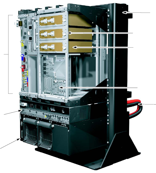
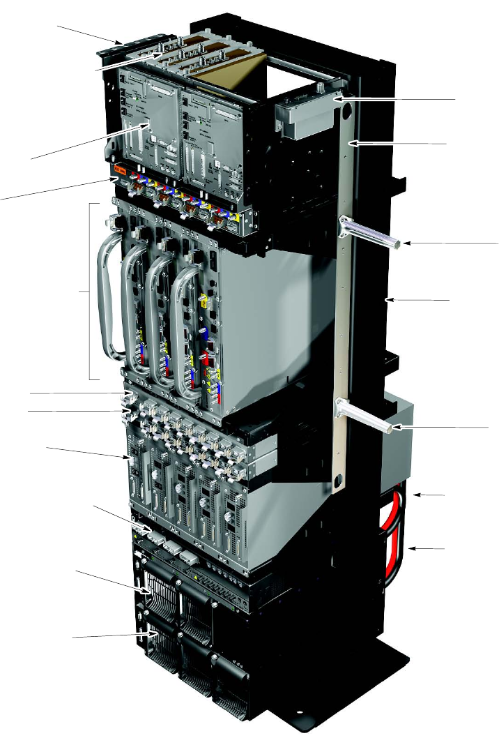
Figure 1 -1 shows a UBS Macro BTS low -tier/low -capacity frame. The capacity of this
configuration is not expandable.
Figure 1 -1 UBS Macro B T S low -tier/low -capacit y fr ame (1000 mm r ack)
ti-cdma-05993.eps
IDRF (Integrated Duplexer and
RX Filter) Shelf
SSI (Site Span I/O); SSI 1
XMI (Transceiver Module Internal) Shelf
- One XMI; XMI 1 (800 MHz or 1.9 GHz
See Notes 2, 3)
- Up to 2 DMIs (Digital Module Internal)
just right of XMI 1
- DMI 1, top; optional DMI 2 or empty
housing, bottom
- IDRF (Integrated Duplexer and RX Filter)
Shelf; in right side of XMI shelf
PDU (+27 V DC Power Distribution Unit)
- One: +27 V DC XMI Power Connector
(PC) and 90A Circuit Breaker (CB)
- Up to 2: +27 V DC DMI PCs and 20A CBs
- One: +27 V DC SSI PC and 20A CB
- No +27 V DC Accessory PCs and CBs
PSM (Power Supply Module) Shelf #1
(See Notes 4,5,6)
- Up to 2 PSMs
- Empty PSM slot with filler panel
- PSM 1 through 3 (left-to-right)
NOTES:
1. Interconnect cabling not shown for clarity.
2. 800 MHz equipment shown; 1.9 GHz similar.
3. 800 MHz XMI is 86 mm wide. 1.9 GHz XMI is 106.3 mm wide.
4. PSM shelf is optional and used instead of +27 V DC power Input.
5. PSM shelf is either -48 V DC or AC.
6. Only -48 V DC PSMs can be used in -48 V DC PSM shelf. Only AC PSMs can be used in AC PSM shelf.
PSM Shelf #1
+27 V DC Power
Cabling
Equipment
Mounting Rack
IDRF (800 MHz or 1.9 GHz
See Note 2)
- Up to 3 IDRFs; one per sector
- IDRF sector 1 through sector 3
(top-to-bottom)
- Antenna RF I/O, front
- BTS RF I/O, rear
1 -10 68P09283A62 -3
PRELIMINARY A UG 2007
R20 1X UBS Macro B T S Hardw are Installation Item identication
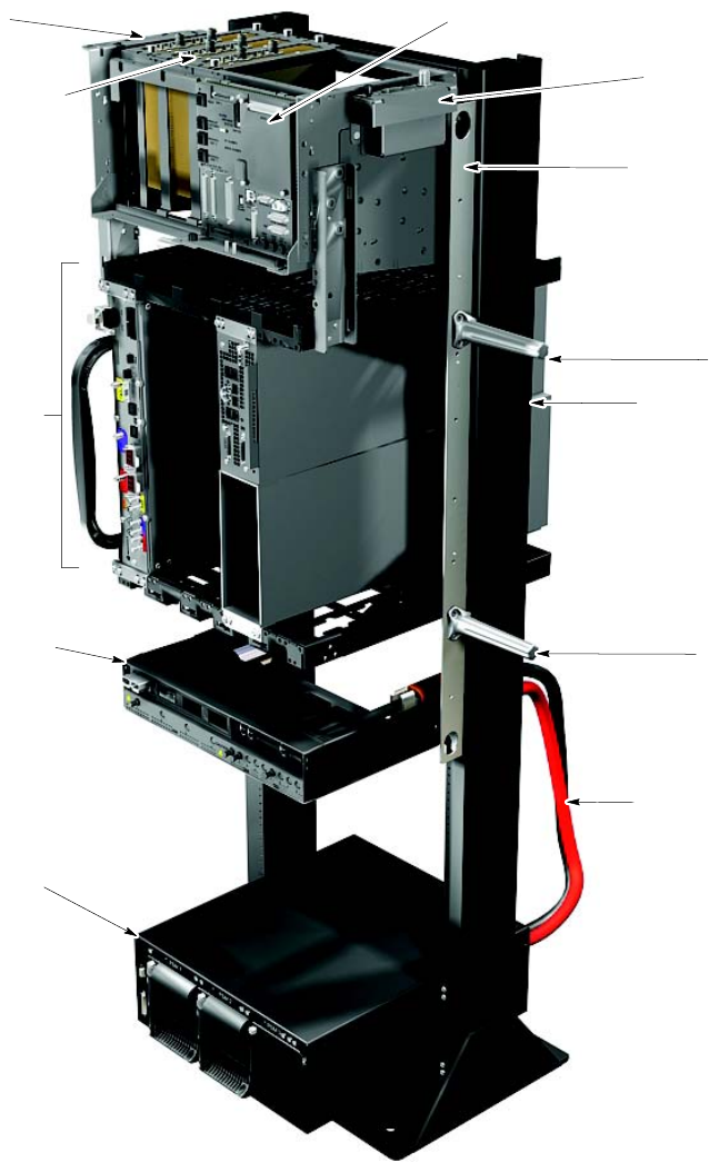
Figure 1 -2 shows a typical low capacity UBS Macro BTS expandable frame. This frame is
expandable to mid -capacity configuration. Expansion to high -capacity configuration is not
currently available.
Figure 1 -2 Low capacit y UBS Macro B T S starter fr ame (1800 mm r ack)
ti-cdma-05994.eps
IDRF (Integrated Duplexer and RX Filter) Shelf
- Up to 3 IDRFs (800 MHz or 1.9 GHz
See Note 2); one per sector
- IDRF sector 1 through sector 3 (left-to-right)
- Antenna RF I/O, top
- BTS RF I/O, bottom
SSI (Site Span I/O)
- One SSI; SSI 1
RX Antenna Sharing Bracket
E-GPS Module
XMI (Transceiver Module Internal) Shelf
- One XMI; XMI 1 (800 MHz or 1.9 GHz
See Notes 2, 3) XMI shelf slot 1
- Up to 2 DMIs (Digital Module Internal)
XMI shelf slot 4
- DMI 1, top; optional DMI 2 or empty
housing, bottom
PDU (+27 VDC Power Distribution Unit)
See Note 8
- One: +27 VDC XMI Power Connector
(PC) and 90A Circuit Breaker (CB)
- Up to 2: +27 VDC DMI PCs and 20A CBs
- One: +27 VDC SSI PC and 20A CB
- No +27 VDC Accessory PCs and CBs
PSM (Power Supply Module) Shelf #1
(See Notes 4,5,6)
- Up to 3 PSMs
- Empty PSM slot with filler panel
- PSM 1 through 3 (left-to-right)
NOTES:
1. Interconnect cabling not shown for clarity.
2. 800 MHz equipment shown; 1.9 GHz similar.
3. 800 MHz XMI is 86 mm wide. 1.9 GHz XMI is 106.3 mm wide.
4. PSM shelf is optional and used instead of+27 VDC power Input.
5. PSM shelf is either -48 VDC or AC.
6. Only -48 VDC PSMs can be used in -48 VDC PSM shelf. Only AC PSMS can be used in AC PSM shelf.
7. Carrier strips are removable.
8. PDU may be moved down 6 rack units to ease future expansion.
PSM Shelf #1
+27 VDC Power
Cabling
Handle
Equipment
Mounting Rack
Handle
Carrier Strip with
Removable Lifting
Handles (one strip
on each side of rack)
See Note 7
68P09283A62 -3 1 -11
PRELIMINARY A UG 2007
Item identication Chapter 1: Introduction and Fr ame Identication
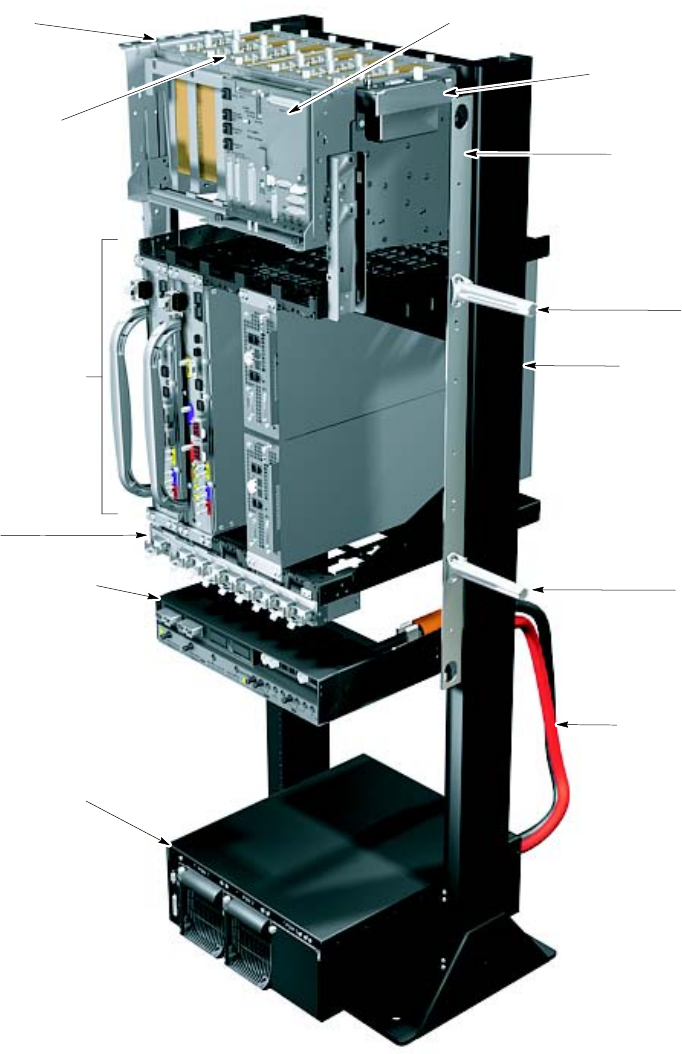
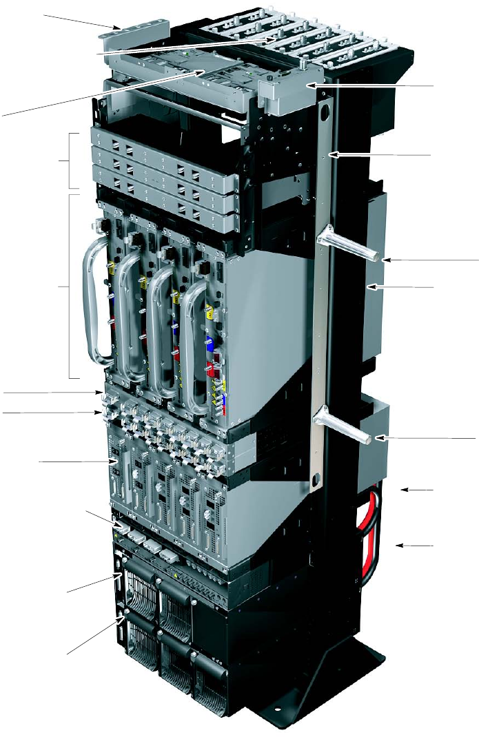
Figure 1 -3 shows a UBS Macro BTS mid -capacity frame. The mid -capacity configuration is
an expansion of the low -capacity configuration. This frame is expandable to high -capacity
configuration, but the high -capacity configuration is not currently available.
Figure 1 -3 UBS Macro B T S mid -capacit y fr ame (1800 mm r ack)
ti-cdma-05995.eps
IDRF (Integrated Duplexer and RX Filter) Shelf
- Up to 6 IDRFs (800 MHz or 1.9 GHz
See Note 2); two sets of IDRFs,
each set with one IDRF per sector
- IDRF sector 1 through sector 3 (left-to-right)
- Antenna RF I/O, top
- BTS RF I/O, bottom
SSI (Site Span I/O)
- One SSI; SSI 1
XMI (Transceiver Module Internal) Shelf
- Two XMIs (800 MHz or 1.9 GHz
See Notes 2, 3); XMI 1, XMI 2 in
XMI shelf slots 1, 2
- Two DMIs (Digital Module Internal)
XMI shelf slot 4
- DMI 1, top; DMI 2, bottom
PDU (+27 VDC Power Distribution Unit)
See Note 8
- One: +27 VDC XMI Power Connector
(PC) and 90A Circuit Breaker (CB)
- Up to 2: +27 VDC DMI PCs and 20A CBs
- One: +27 VDC SSI PC and 20A CB
- No +27 VDC Accessory PCs and CBs
PSM (Power Supply Module) Shelf #1
(See Notes 4,5,6)
- Up to 3 PSMs
- Empty PSM slot with filler panel
- PSM 1 through 3 (left-to-right)
NOTES:
1. Interconnect cabling not shown for clarity.
2. 800 MHz equipment shown; 1.9 GHz similar.
3. 800 MHz XMI is 86 mm wide. 1.9 GHz XMI is 106.3 mm wide.
4. PSM shelf is optional and used instead of+27 VDC power Input.
5. PSM shelf is either -48 VDC or AC.
6. Only -48 VDC PSMs can be used in -48 VDC PSM shelf. Only AC PSMS can be used in AC PSM shelf.
7. Carrier strips are removable.
8. PDU may be moved down 6 rack units to ease future expansion.
PSM Shelf #1
+27 VDC Power
Cabling
Handle
Equipment
Mounting Rack
Handle
Carrier Strip with
Removable Lifting
Handles (one strip
on each side of rack)
See Note 7
RX Splitter
RX Antenna Sharing Bracket
E-GPS Module
1 -12 68P09283A62 -3
PRELIMINARY A UG 2007
R20 1X UBS Macro B T S Hardw are Installation Item identication
Figure 1 -4 shows a typical fully expanded high capacity 800 MHz UBS Macro BTS frame.
Figure 1 -4 High capacit y 800 MHz UBS Macro B T S fully expanded fr ame (1800 mm r ack)
ti-cdma-05996.eps
NOTES:
1. Interconnect cabling not shown for clarity.
2. 800 MHz equipment shown.
3. 800 MHz XMI is 86 mm wide.
4. PSM shelves are optional and used
instead of+27 VDC power Input.
PSM (Power Supply Module) Shelf #1
(See Notes 4,5,6)
- Up to 3 PSMs
- PSM 1 through 3 (left-to-right)
PSM (Power Supply Module) Shelf #2
(See Notes 4,5,6)
- Up to 2 PSMs
- Empty PSM slot with filler panel
- PSM 1 through 3 (left-to-right)
PDU (+27 VDC Power Distribution Unit)
- Up to 4: +27 VDC XMI Power Connectors
(PCs) and 90A Circuit Breakers (CBs)
- Up to 5: +27 VDC DMI PCs and 20A CBs
- Up to 2: +27 VDC SSI PCs and 20A CBs
- Up to 2 sets of 3: +27 VDC Accessory PCs
- Up to 2: 10A CBs; one CB per set of 3+27
VDC Accessory PCs. None equipped.
DMI (Digital Module Internal) Shelf
- Up to 5 DMIs
- DMI 1 through 5 (left-to-right)
RX Splitter
RX Antenna Sharing Bracket
IDI/BSI
XMI (Transceiver Module Internal) Shelf
- Up to 4 XMIs (See Notes 2, 3);
XMI 1through XMI 4 in XMI shelf
slots 1 through 4 (left-to-right)
- One Ancillary slot 5 shown empty
TX Combiner, 4:1
(See Note 2)
SSI (Site Span I/O) Shelf
- Two SSIs
- SSI 2, SSI 1 (left-to-right)
IDRF (Integrated Duplexer and RX Filter) Shelf
- Up to 3 IDRFs (See Note 2); one per sector
- IDRF sector 1 through 3 (left-to-right)
- Antenna RF I/O, top
- BTS RF I/O, bottom
Carrier Strip with
Removable Lifting
Handles (one strip
on each side of rack)
See Note 7
Handle
E-GPS
Equipment
Mounting Rack
Handle
PSM Shelf #2
+27 VDC Power
Cabling
PSM Shelf #1
+27 VDC Power
Cabling
5. Both PSM shelves are either -48 VDC or AC.
6. Only -48 VDC PSMs can be used in -48 VDC PSM shelf.
Only AC PSMs can be used in AC PSM shelf.
7. Carrier strips are removable
68P09283A62 -3 1 -13
PRELIMINARY A UG 2007
Item identication Chapter 1: Introduction and Fr ame Identication
Figure 1 -5 shows a typical fully expanded high -capacity 1.9 GHz UBS Macro BTS frame.
Figure 1 -5 High -capacit y 1.9 GHz UBS Macro B T S fully expanded fr ame (1800 mm
r ack)
ti-cdma-05997.eps
PSM (Power Supply Module) Shelf #1
(See Notes 4,5,6)
- Up to 3 PSMs
- PSM 1 through 3 (left-to-right)
PSM (Power Supply Module) Shelf #2
(See Notes 4,5,6)
- Up to 2 PSMs
- Empty PSM slot with filler panel
- PSM 1 through 3 (left-to-right)
PDU (+27 VDC Power Distribution Unit)
- Up to 4: +27 VDC XMI Power Connectors
(PCs) and 90A Circuit Breakers (CBs)
- Up to 5: +27 VDC DMI PCs and 20A CBs
- Up to 2: +27 VDC SSI PCs and 20A CBs
- Up to 2 sets of 3: +27 VDC Accessory PCs
- Up to 2: 10A CBs; one CB per set of 3+27
VDC Accessory PCs. None equipped.
DMI (Digital Module Internal) Shelf
- Up to 5 DMIs
- DMI 1 through 5 (left-to-right)
RX Splitter
RX Antenna Sharing Connector
IDI/BSI
SSI (Site Span I/O) Shelf
- Up to 2 SSIs
- SSI 1, 2 (left-to-right)
Carrier Strip with
Removable Lifting
Handles (one strip
on each side of rack)
See Note 7
Handle
E-GPS
Equipment
Mounting Rack
Handle
PSM Shelf #2
+27 VDC Power
Cabling
PSM Shelf #1
+27 VDC Power
Cabling
IDRF (Integrated Duplexer and RX Filter) Shelf
- Up to 6 IDRFs (See Note 2); two sets of IDRFs,
each set with one IDRF per sector
- IDRF sector 1 through sector 3 (left-to-right)
- Antenna RF I/O, top
- BTS RF I/O, bottom
Six 2:1 TX Cavity Combiners
(See Note 2)
XMI (Transceiver Module Internal) Shelf
- Up to 4 XMIs (See Notes 2, 3);
XMI 1through XMI 4 in XMI shelf
slots 1 through 4 (left-to-right)
NOTES:
1. Interconnect cabling not shown for clarity.
2. 1.9 GHz equipment shown.
3. 1.9 GHz XMI is 106.3 mm wide.
4. PSM shelves are optional and used
instead of+27 VDC power Input.
5. Both PSM shelves are either -48 VDC or AC.
6. Only -48 VDC PSMs can be used in -48 VDC PSM shelf.
Only AC PSMs can be used in AC PSM shelf.
7. Carrier strips are removable
1 -14 68P09283A62 -3
PRELIMINARY A UG 2007
R20 1X UBS Macro B T S Hardw are Installation Item identication
Items to be installed
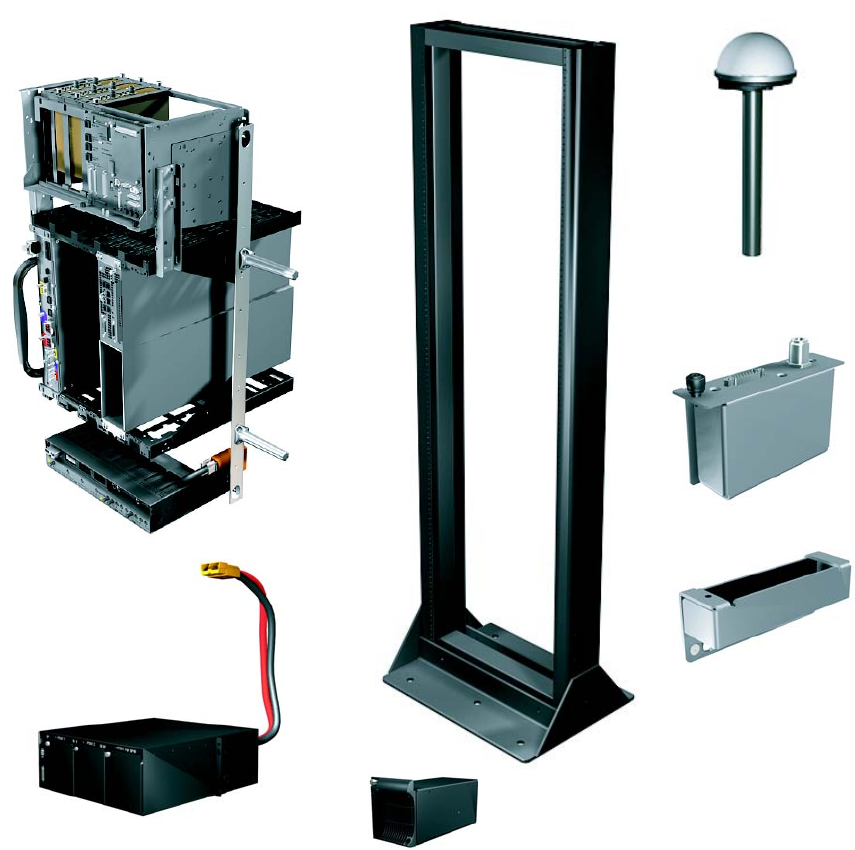
Figure 1 -6 shows the items to be installed.
Figure 1 -6 Items to install
ti-cdma-06008.eps
Low Capacity, +27 VDC
UBS Macro BTS Assembly
Tall Rack
Optional -48V DC or 220 V AC
PSM Shelf (without PSMs) Optional -48V DC or 220 V AC
PSM (two for low capacity)
E-GPS Mounting Bracket
E-GPS Module
Optional
RGPS Head
68P09283A62 -3 1 -15
PRELIMINARY A UG 2007
T ools and materials Chapter 1: Introduction and Fr ame Identication
Tools and materials■■■■■■■■■■■■■■■■■■■■■■■■■■■■■■■■■■■■■■■■■■■■■■■■■■■■■■■■■■■■■■
■
■
Required tools and materials
The following tools and materials are required to perform the installation:
•Battery driver , capable of 3.95 N -m to 5.09 N -m (35 -45 in -lb) torque
•T20 and T25 TORX bits with 12 inch extension
•T orque drivers; 1 N -m, 2.3 N -m, 4.8 N -m +/ - 10%
•8 mm SMA connector torque wrench; 1.02 N -m (9 in -lb) +/ - 10%
•19 mm N -type connector torque wrench; 4.3 N -m (38 in -lb) +/ - 10%
•Phillips screwdriver
•Flat screwdriver
•3/8 -inch ratchet -5.6 N -m (50 in -lb)
•8 -mm socket
•19 -mm socket
•10 -mm deep set socket
•9/16 -inch socket
•3/16 -inch socket
•Side cutters
•Dust mask
•Safety glasses
•Ear plugs
•Marker for marking outline on floor
•T ape measure with millimeter scale, capable measuring up to 1200 mm or with inch scale,
capable measuring up to 48 inches
•Shop vacuum
•Cable tie -wraps
•Scissors or knife
•0.25 W SMA -type terminators for any unused directional port connectors on an
IDRF - customer supplied
1 -16 68P09283A62 -3
PRELIMINARY A UG 2007

R20 1X UBS Macro B T S Hardw are Installation T ools and materials
•50 W N -type terminators for any unused TX/RX connectors on an IDRF - customer supplied
•Digital Multi -Meter (DMM) Fluke Model 8062A with Y8134 test lead kit or equivalent; used
for precision DC and AC measurements, requiring 4 -1/2 digits.
•One DC connector housing per DC power feed (see T able 2 -8 for quantity of power feeds)
Orange DC connector housing used for +27 V DC application (see T able 2 -14 for
part information).
Blue DC connector housing used for –48 V DC application (see T able 2 -15 for part
information).
•DC connector cable clamps for power cable (see T able 2 -14 or T able 2 -15 for part
information).
•DC connector housing contacts/lugs for power cable (see T able 2 -14 or T able 2 -15 for
part information).
•Crimper tool - Anderson P ower Products part number 1368 - Hydraulic hand tool, maximum
cable size of 300 MCM.
Other tools are required to install the rack to the floor . The method of installing the rack to the
floor , as specified by a Structural Engineer , determines what additional tools are required.
Recommended tools
The following tools are not required, but they may make the installation easier:
•Long screwdriver extension
•Long socket wrench extension
•Mechanical hoist capable of lifting 100 kg, 2 m high
•Banding cutter
68P09283A62 -3 1 -17
PRELIMINARY A UG 2007

Unpacking Instructions Chapter 1: Introduction and Fr ame Identication
Unpacking Instructions
■■■■■■■■■■■■■■■■■■■■■■■■■■■■■■■■■■■■■■■■■■■■■■■■■■■■■■■■■■■■■■
■
■
Unpacking the carrier strip assembly
The UBS Macro BTS carrier strip assembly includes the low -capacity frame equipment
pre -mounted and cabled. This assembly consists of the following equipment:
•One set of IDRFs, up to three IDRFs.
•One S SI
•One XMI
•One DMI
•PDU with one +27 V DC input power feed and circuit breaker/output power connector
assemblies as follows: XMI 1, DMI 1, DMI 2 and S SI 1.
The STGN4034 Installation Kit is also packaged with the UBS Macro carrier strip
assembly . The installation kit contains all of the M5 x 12 mm screws needed to rack
mount the equipment.
The UBS Macro BTS carrier strip assembly is shipped in a large carton that is banded to a pallet.
F ollow the steps in Procedure 1 -1 to unpack the carrier strip assembly .
Procedure 1 -1 Unpacking the carrier strip assembly
1
Cut the bands that hold the carton to the pallet.
2
Lift the carton up and off of the pallet. Remove the cut bands
3
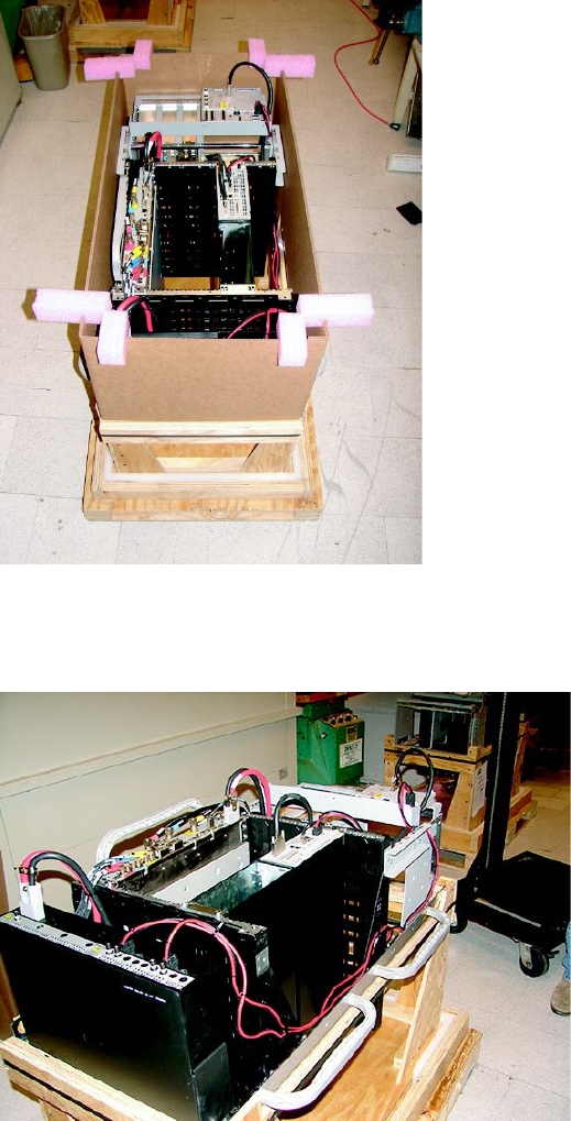
Remove the inner carton support (see Figure 1-7 ).
The carrier strip assembly is sitting on a wooden support (see
Figure 1-8 ).
4
Locate the STGN4034 Installation Kit that is packaged with the UBS Macro
carrier strip assembly .
5
Inspect the carrier strip assembly for damage.
1 -18 68P09283A62 -3
PRELIMINARY A UG 2007
R20 1X UBS Macro B T S Hardw are Installation Unpacking Instructions
Figure 1 -7 Carrier strip assembly with inner carton support
ti-cdma-06026.eps
Figure 1 -8 Carrier strip assembly with inner carton support remo v ed
ti-cdma-06027.eps
68P09283A62 -3 1 -19
PRELIMINARY A UG 2007

Unpacking Instructions Chapter 1: Introduction and Fr ame Identication
Unpacking accessory equipment
UBS Macro BTS accessory equipment is shipped in smaller cartons. The quantity of cartons
is dependent on the BTS site configuration and options. F ollow the steps in Procedure 1 -2 to
unpack the accessory equipment.
Procedure 1 -2 Unpacking accessory equipment
1
Open an accessory equipment carton.
2
Inspect the contents of the carton for damage.
3
V erify that the carton contains all of the equipment stated on the packing list.
4
Repeat this procedure for each carton in the shipment.
1 -20 68P09283A62 -3
PRELIMINARY A UG 2007

C h a p t e r
2
UBS Macro BTS Installation Procedure■■■■■■■■■■■■■■■■■■■■■■■■■■■■■■■■■■■■■■■■■■■■■■■■■■■■■■■■■■■■■■
■
■
■
■
68P09283A62 -3 2 -1
A UG 2007 PRELIMINARY
Ov erview Chapter 2: UBS Macro B T S Installation Procedure
Overview
■■■■■■■■■■■■■■■■■■■■■■■■■■■■■■■■■■■■■■■■■■■■■■■■■■■■■■■■■■■■■■
■
■
Introduction
This chapter provides the information and procedures to install the items and cabling for the
UBS Macro BTS . Both pictorial and textual information is presented.
The installation is broken into a set of tasks. Each set of tasks is broken down into a set of steps.
Individual tasks or steps are based on the overall installation sequence and must not be
performed randomly .
Structural engineer
A Structural Engineer has to determine the method and equipment needed to mount the rack to
the floor .
Required items
F or each set of tasks, a list of tools and items is given that covers those specific tasks.
A full list of tools is given in T ools and materials on page 1 - 16 .
Cabling and conguration options
All of the configurations require unique cables and/or items. Installation of all cables and all
items is covered. When applicable, the cabling and configuration options are called out. Not all
cables or items covered in this manual should be installed. Consult the site plan to determine
exactly what items to install.
Color coding
Many of the connectors and cables are color coded. As the cables are installed, the cable
color code should match the color code of the connector . Not all cables and connectors are
color coded.
Some, but not all, of the color coding is called out in the installation procedures. The scheme of
the color codes is shown in T able 2 -1 and T able 2 -2 .
2 -2 68P09283A62 -3
PRELIMINARY A UG 2007

R20 1X UBS Macro B T S Hardw are Installation Ov erview
Table 2 -1 Color code – DC power connectors/cables
Color
Represents
ORANGE +27 V DC P ower
BL UE
-48 V DC P ower
Table 2 -2 Color code - RF Equipment and Connectors/Cables
Color
Represents
ORANGE 800 MHz RF equipment
BL UE
1.9 GHz RF equipment
GREEN 2.1 GHz RF equipment
RED
Sector 1
BL UE
Sector 2
YELLOW Sector 3
GREY
RFL (reflected) Main
BROWN
RFL DIV (reflected diversity)
WHITE
F or RF use, it can mean:
•Main
•FWD (forward main)
BLACK F or RF use, it can mean:
•Diversity
•FWD DIV (forward diversity)
68P09283A62 -3 2 -3
PRELIMINARY A UG 2007

Cable list, diagr ams and connectors Chapter 2: UBS Macro B T S Installation Procedure
Cable list, diagrams and connectors■■■■■■■■■■■■■■■■■■■■■■■■■■■■■■■■■■■■■■■■■■■■■■■■■■■■■■■■■■■■■■
■
■
Overview
This section gives a UBS Macro BTS external input/output (I/O) cable run list – a list of cables
and the end connection points. This can be used as a check -off sheet during installation. F or any
item that cables connect to, that item and the associated connectors are shown.
UBS Macro BTS external I/O cable run list
T able 2 -3 gives the UBS Macro BTS external input/output cable run list. Not all cables are
needed for all configurations.
Each row in T able 2 -3 is a separate unique cable run even if the reference designator
and the part number are duplicated.
Table 2 -3 UBS Macro B T S external I/O cable run list
From T oReference
(used in
manual)
Part number
Item
Connector
Item
Connector
Notes
DD
Customer
R ack Double-studs
Site Master
Ground Bar
(MGB)
Customer
Earth Ground
Cable/W ire
(4 A WG
or larger
diameter)
NN
One of:
3086039H10
through H14
(Note 1)
RGPS
Head
12-pin
Circular
(Deutsch)
RGPS
Lightning
Arrester
RGPS
Lightning
Arrester
RGPS Head
Cable,
shielded
twisted pair
AA
3086433H14 S SI RGPS
(15-pin D)
RGPS
Lightning
Arrester
RGPS
Lightning
Arrester
RGPS Head
Cable,
shielded
twisted pair
W
CGDS19797321 S SI SP ANS
(37-pin D)
Customer Equipment
T1/E1 Bal.,
shielded
twisted
pair cable
(Note 2)
Continued
2 -4 68P09283A62 -3
PRELIMINARY A UG 2007

R20 1X UBS Macro B T S Hardw are Installation Cable list, diagr ams and connectors
Table 2 -3 UBS Macro B T S external I/O cable run list (Continued)
From T oReference
(used in
manual)
Part number
Item
Connector
Item
Connector
Notes
None
Customer S SI
(E1
Daughter
Card)
SP AN
RX/TX #
(BNCs)
Customer Equipment
E1 Unbal.
75-Ohm Coax
Up to 8 cables
(Note 2)
X
CGDS19797321 S SI CUSTOMER
IP 1-12 OP 1-4
(37-pin D)
Customer Equipment Customer
Input/Output
(IP/OP)
X
CGDS19797321 S SI CUSTOMER
IP 13-24
OP 5-8
(37-pin D)
Customer Equipment Customer
Input/Output
(IP/OP)
DC Customer PDU +27
V DC
P ower
Input
Cable
Orange
(2-contact,
Anderson
SB -350)
DC P ower
W ires; Red
& Black
Orange
(2-contact,
Anderson
SB -350)
+27 V DC
P ower From
Customer
Source
CC Customer -48 V
DC PSM
Shelf
P ower
Input
Cable
Blue
(2-contact,
Anderson
SB -350)
DC P ower
W ires; Blue
& Black
Blue
(2-contact,
Anderson
SB -350)
-48 V DC
P ower From
Customer
Source
AC Customer AC PSM
Shelf
AC Input
T erminal Block
Customer Equipment AC P ower
From
Customer
Source
None
Customer Sector 1
IDRF
TX/RX MAIN
(N-type,
coaxial)
Sector
1 TX/RX
Main Ant.
Cable
N-type,
coaxial
RF Ant.,
50-Ohm
Coaxial
(Note 3)
None
Customer Sector 2
IDRF
TX/RX MAIN
(N-type,
coaxial)
Sector
2 TX/RX
Main Ant.
Cable
N-type,
coaxial
RF Ant.,
50-Ohm
Coaxial
(Note 3)
None
Customer Sector 3
IDRF
TX/RX MAIN
(N-type,
coaxial)
Sector
3 TX/RX
Main Ant.
Cable
N-type,
coaxial
RF Ant.,
50-Ohm
Coaxial
(Note 2)
None
Customer Sector 1
IDRF
RX DIV
(N-type,
coaxial)
Sector 1
RX Div .
Ant. Cable
N-type,
coaxial
RF Ant.,
50-Ohm
Coaxial
(Note 2)
Continued
68P09283A62 -3 2 -5
PRELIMINARY A UG 2007

Cable list, diagr ams and connectors Chapter 2: UBS Macro B T S Installation Procedure
Table 2 -3 UBS Macro B T S external I/O cable run list (Continued)
From T oReference
(used in
manual)
Part number
Item
Connector
Item
Connector
Notes
None
Customer Sector 2
IDRF
RX DIV
(N-type,
coaxial)
Sector 2
RX Div .
Ant. Cable
N-type,
coaxial
RF Ant.,
50-Ohm
Coaxial
(Note 2)
None
Customer Sector 3
IDRF
RX DIV
(N-type,
coaxial)
Sector 3
RX Div .
Ant. Cable
N-type,
coaxial
RF Ant.,
50-Ohm
Coaxial
(Note 2)
1. Cables 3086039H10 through H14 are various lengths; where the part number suffix
indicates the following cable lengths: H10 = 15 m (50 ft), H11 = 38 m (125 ft), H12 =
76 m (250 ft), H13 =152 m (500 ft) and H14 = 304 m (1000 ft). Cables H10 and H11
are included in Motorola option T472AG and T472AH, respectively . Cables H12, H13
and H14 are included in Motorola option T472AJ , T472AK and T472AL respectively .
2. Cable may be connected to a lightning arrester .
Connector locations
Figure 2 -1 through Figure 2 -4 show the items that external cables connect to . F or each
connector , the name is stated and where the associated cable goes.
IDRF I/O details
Figure 2 -1 shows connector locations and usage for the 800 MHz IDRF .
Figure 2 -2 shows connector locations and usage for the 1.9 GHz IDRF .
2 -6 68P09283A62 -3
PRELIMINARY A UG 2007
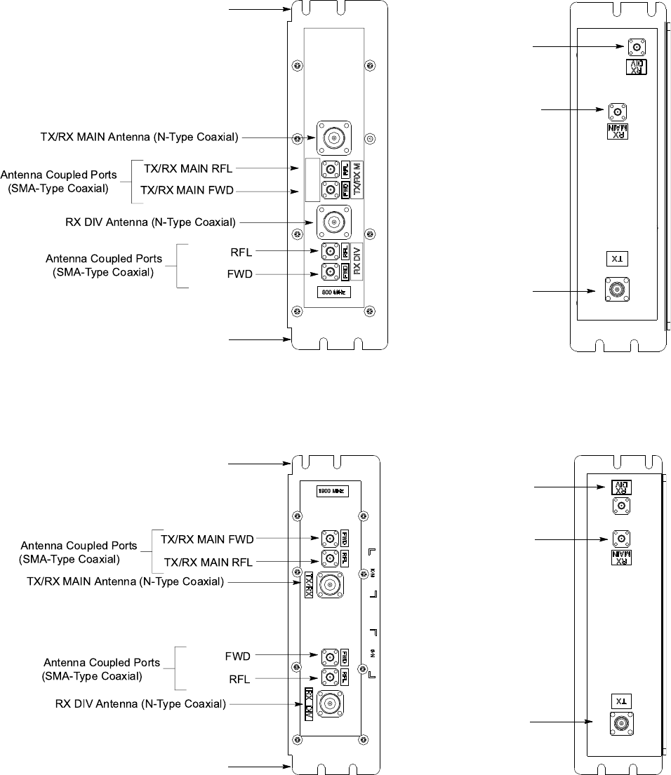
R20 1X UBS Macro B T S Hardw are Installation Cable list, diagr ams and connectors
Figure 2 -1 800 MHz IDRF I/O connectors
TOP VIEW BOTTOM VIEW
RX DIV to XMI
(QMA-Type Coaxial)
TX from XMI
(Sector TX RF)
(QN-Type Coaxial)
RX MAIN to XMI
(QMA-Type Coaxial)
ti-cdma-06010.eps
TX/RX MAIN Antenna (N-T ype Coaxial)
Antenna Coupled Ports
(SMA-Type Coaxial)
TX/RX MAIN RFL
TX/RX MAIN FWD
Antenna Coupled Ports
(SMA-Type Coaxial)
RX DIV
RFL
RX DIV
FWD
RX DIV Antenna (N-T ype Coaxial)
(Sector RX RF)
(Sector RX RF)
TX/RX M
RX DIV
FWD CPLR
LABEL
Mounting Tab
Mounting Tab
NOTE:
1. Connector locations may vary
depending on the IDRF supplier.
Figure 2 -2 1.9 GHz IDRF I/O connectors
TOP VIEW BOTTOM VIEW
RX DIV to XMI
(QMA-Type Coaxial)
TX from XMI
(Sector TX RF)
(QN-Type Coaxial)
RX MAIN to XMI
(QMA-Type Coaxial)
ti-cdma-06009.eps
TX/RX MAIN Antenna (N-T ype Coaxial)
Antenna Coupled Ports
(SMA-Type Coaxial)
RX DIV
RFL
RX DIV
FWD
Antenna Coupled Ports
(SMA-Type Coaxial) TX/RX MAIN RFL
TX/RX MAIN FWD
RX DIV Antenna (N-T ype Coaxial)
Mounting Tab
(Sector RX RF)
(Sector RX RF)
Mounting Tab
NOTE:
1. Connector locations may vary
depending on the IDRF supplier.
68P09283A62 -3 2 -7
PRELIMINARY A UG 2007
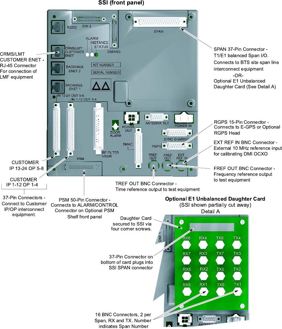
R20 1X UBS Macro B T S Hardw are Installation Cable list, diagr ams and connectors
Figure 2 -3 S SI front panel connectors
SSI (front pane l)
CUST OMER
IP 13-24 OP 5-8
CUST OMER
IP 1-12 OP 1-4
37-Pin Connectors -
Connect to Customer
IP/OP interconnect
equipment.
PSM 50-Pin Connector -
Connects to ALARM/CONTROL
Connector on Optional PSM
Shelf front panel
RGPS 15-Pin Connector -
Connects to E-GPS or Optional
RGPS Head
SP AN 37-P in Connector -
T1/E1 balanced Span I/O.
Connects to BTS site span line
interconnect equipment
-OR-
Optional E1 Unbalanced
Daughter Card (See Detail A)
Detail A
Optional E1 Unbalance d Daughter Card
(SSI sh own partially cut away)
Dau ghter Card
sec ured to SSI via
four corner scre ws.
37-Pin C onnector on
bottom o f card plugs into
SSI SP AN connector
16 BNC Conn ectors , 2 per
Span , RX an d TX. Number
indicates S pan Number
ti-cdma-05698.eps
TREF OUT BNC Connector -
Time reference o utput to test equipment
FREF OUT BNC Connector -
Frequenc y refere nce output
to test equipmen t
EXT REF IN BNC Connector -
External 10 MH z reference input
for calibrating DM I OCXO
CRMS/LMT
CUST OMER EN ET -
RJ-45 Connector
For connection o f
LMF equipment
68P09283A62 -3 2 -9
PRELIMINARY A UG 2007
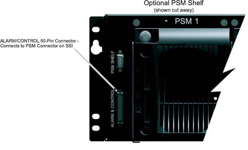
Cable list, diagr ams and connectors Chapter 2: UBS Macro B T S Installation Procedure
PSM shelf front panel I/O details
Figure 2 -4 shows the front panel connector locations and usage for the optional PSM shelf .
Figure 2 -4 PSM shelf front panel connectors
ti-cdma-05699.eps
Optional PSM Shelf
(sh own cut away)
ALARM/CONTROL 50-Pin Connector -
Connects to PSM Connector on SSI
2 -10 68P09283A62 -3
PRELIMINARY A UG 2007
R20 1X UBS Macro B T S Hardw are Installation Full installation sequence
Full installation sequence■■■■■■■■■■■■■■■■■■■■■■■■■■■■■■■■■■■■■■■■■■■■■■■■■■■■■■■■■■■■■■
■
■
Overview
The installation of the UBS Macro BTS is composed of two parts to be performed in this order:
1. V erifying site and equipment
2. Physical installation
Once the site is verified, the BTS can be physically installed.
Details to perform each part are given here along with any prerequisites.
Prerequisites
This document is not a planning guide and is not meant to provide planning information. All site
planning, including power requirements and installation of site power , must be completed before
performing the installation. The site verification will help verify this prerequisite has been met.
A Structural Engineer has been consulted and has determined the method to mount the rack to
the floor .
Verifying site and equipment
This can be performed at any time prior to the physical installation. V erifying site and equipment
is composed of two portions to be performed in this order:
1. Site verifications - Refer to Site verification on page 2 - 15 to verify the site.
2. Unpack and identify the equipment - Refer to Unpacking Instructions on page 1 - 18 and
unpack the various cartons. Refer to Figure 1 -6 and verify the correct equipment is
present. The exact number and type of equipment is site dependent.
Physical installation
Recommendations
Motorola recommends performing the physical installation all at once and not in multiple stages.
Motorola recommends installing cable ties to eliminate confusion and clutter .
68P09283A62 -3 2 -11
PRELIMINARY A UG 2007

Full installation sequence Chapter 2: UBS Macro B T S Installation Procedure
Color code
F ollow the color codes for the cables and connectors when applicable. Refer to Overview on
page 2 - 2 of this chapter for a detailed description of the color codes.
Default values
Unless otherwise specified, use these default values during the installation.
•All screws are M5 x 12 mm and require a T25 TORX bit. These screws are included in the
STGN4034 Installation Kit that is packaged with the UBS Macro carrier strip assembly .
•T orque values are to be within +/ -10% of value shown.
•Tighten screws and bolts to 4.77 N -m (42 in -lb).
•Maximum torque for the IDRF screws is 2.37 N -m (21 in -lb).
•Tighten SMA connectors to 1.02 N -m (9 in -lb).
•Tighten N -connectors on cables to 4.3 N -m (38 in -lb).
Preview of installation tasks
This section provides a preview of all of the tasks to be performed to install the UBS Macro
BTS as well the sequence of those tasks. Each specific task is detailed in its own section later
in this manual.
Each item number below corresponds to a specific task number . The task number is
used to identify the task and its occurrence within the overall installation sequence.
** indicates an optional task. The system configuration determines if the optional task
is to be performed or if it can be skipped.
P erform the following tasks in the order shown when installing the UBS Macro BTS .
1. ** Install the optional RGPS head and route cable (NN) to the BTS site. Skip this task if
the optional RGPS head is not required.
2. Mount rack to floor using the hardware, tools, and procedures defined by your Structural
Engineer . Motorola recommends using 6 carbon steel grade 8.8 M12 bolts.
3. Install earth ground wire/cable (DD) between the site Master Ground Bar (MGB) and
equipment rack. A ttach ground wire to the top of equipment rack using 2 studs/nuts and a
10 mm socket and ratchet. Tighten to 5.65 N -m (50 in -lb).
4. ** P erform this task for -48 V DC or 220 V AC UBS only . Install the PSM shelf to the bottom
of the rack using 6 screws; three screws on each left and right side. Install the appropriate,
-48 V DC or 220 V AC , PSMs into PSM shelf slots 1 and 2.
2 -12 68P09283A62 -3
PRELIMINARY A UG 2007
R20 1X UBS Macro B T S Hardw are Installation Full installation sequence
5. Mount the UBS Macro BTS carrier strip assembly to the rack at the predetermined height.
First, measure and install 2 hanger screws in the rack rails; one screw on each left and
right side at the proper height. Second, four people lift the UBS Macro BTS carrier strip
assembly via the carrier strip handles and hang the assembly on the 2 hanger screws in
the rack rails. Install 2 screws in the keyholes at the bottom of each carrier strip. Third,
completely fasten the UBS assembly/carrier strips using 22 more screws; 11 screws on
each left and right side. Completely tighten these 22 crews. Then completely tighten the 4
screws in the keyholes.
6. ** Install the additional equipment required to expand the UBS Macro BTS low -capacity
starter/expansion frame to the mid -capacity frame configuration. If the initial UBS Macro
BTS installation is for a low -capacity frame configuration, skip this task and go to T ask
7. P erform this task only if the initial UBS Macro BTS installation is for a mid -capacity
frame configuration.
7. ** F or -48 V DC or 220 V AC UBS only , connect the +27 V DC power output cable from
the rear of the PSM shelf to the +27 V DC power input cable on the rear of the PDU .
Connect the 50 -conductor cable (supplied with PSM shelf) between the PSM shelf front
panel ALARM/CONTROL connector and S SI PSM connector .
8. Route the customer supplied TX/RX main and RX diversity antenna cables to the front of
the Integrated Duplexer RX Filters (IDRFs) at the top of the frame. Connect each antenna
cable to the corresponding IDRF connector .
9. Connect customer supplied 0.25 W , 50 -Ohm, SMA -type terminators to unused directional
coupler port connectors on the front of the IDRFs.
10. ** Install optional RGPS cable (AA). Connect the 15 -pin D -connector to the RGPS connector
on the front of the S SI. Route the loose end of the cable to the RGPS lightning arrester and
connect the wires there. Skip this task if the optional RGPS head is not required.
11. ** Install T1/E1 balanced span I/O cable (W). Connect the 37 -pin D -connector to the SP AN
connector on the front of the S SI. Route the loose end of the cable to the site span line
interconnect equipment and connect the wires.
12. ** Install E1 unbalanced span I/O coaxial cables (customer supplied). Route 75 -Ohm
coaxial cables, with BNC connectors, from the site span line interconnect equipment to the
S SI. Connect each cable to the corresponding BNC connector on the S SI E1 daughter card.
13. ** Install Customer Alarm Input/Output (IP/OP) cables (X). Connect the 37 -pin D -connector
to the corresponding CUSTOMER IP 1 -12 OP 1 -4 connector and CUSTOMER IP 13 -24 OP
5 -8 connector on the front of the S SI. Route the loose end of the cables to the customer
IP/OP interconnect equipment and connect the wires.
14. ** Ensure that all circuit breakers are open on the PDU . F or +27 V DC UBS only: attach an
Orange 2 -contact DC connector to Red and Black wires. Connect this Orange connector
to the +27 V DC input power cable on the rear of the PDU . Route the loose ends of the
wires to the site +27 V DC source and connect the wires.
15. ** Ensure that all circuit breakers are open on the PDU . F or -48 V DC UBS only: attach a
Blue 2 -contact DC connector to Blue and Black wires. Connect this Blue connector to the
Blue DC INP UT connector on the rear of the -48 V DC PSM shelf . Route the loose ends of
the wires to the site -48 V DC source and connect the wires.
16. ** Ensure that all circuit breakers are open on the PDU . F or 220 V AC UBS only: attach
customer supplied wiring and conduit for 220 V AC lines. Connect wires and required
insertion bridges to the AC INP UT terminal block on the rear of the AC PSM shelf . Route
the loose ends of the wires to the site 220 V AC source and connect the wires.
68P09283A62 -3 2 -13
PRELIMINARY A UG 2007
Full installation sequence Chapter 2: UBS Macro B T S Installation Procedure
A fter performing all of the necessary tasks, complete the installation by performing the
following:
•Clean up the site.
•Fill out installation check off sheet.
2 -14 68P09283A62 -3
PRELIMINARY A UG 2007
R20 1X UBS Macro B T S Hardw are Installation Site v erication
Site verication
■■■■■■■■■■■■■■■■■■■■■■■■■■■■■■■■■■■■■■■■■■■■■■■■■■■■■■■■■■■■■■
■
■
Site installation checks
V erify that the site is ready for BTS installation before performing the physical installation.
A detailed layout of the site is provided with the site -specific documentation. Before installing
the hardware, compare the information presented here to the site -specific documentation layout
and verify with the Site Manager for the following:
•All cable trays are installed.
•All external signal cables are connected.
•Site is clean.
•Site specific documentation covering all site dependent installation information is available.
•The installation area has restricted access. Equipment is meant to be installed and
operated in a restricted access location. In order to maintain UL listing, equipment must
be installed in a restricted access area.
•The site can maintain the required temperature range.
•The layout meets the minimum clearance requirements for the equipment as listed in
T able 2 -5 ,T able 2 -6 and T able 2 -7 .
•All building DC power cables are connected.
•The building meets the voltage and power requirements shown in
Site description (as
built)
documents.
•P ower cables are present that meet the requirements shown in T able 2 -8 .
•The procedure, tools, and equipment required to mount the rack to the floor are specified
by a Structural Engineer .
•The site can meet the footprint dimensions (as shown in Figure 2 -5 ) and not violate any of
the required clearances.
•Site grounding is according to Grounding Guidelines for Cellular R adio Installations
(Motorola part number 68P81150E62).
•The screen (outer shield) of the RF antenna coaxial cable must be connected to earth
(grounded) at the entrance to the building. This should be done in accordance with
applicable national electrical installation codes (Section 820.93 of the National Electrical
Code, ANSI/NFP A 70.
•V erify that the Master Ground Bar is connected to a solid earth ground. This is required
to ensure protection from hazardous voltages by providing a high integrity protective
earthing circuit when the frame is later grounded to the Master Ground Bar .
68P09283A62 -3 2 -15
PRELIMINARY A UG 2007

Site v erication Chapter 2: UBS Macro B T S Installation Procedure
•The frames can be mounted as specified in the site -specific documentation.
•Each frame has its own main power cut off .
Motorola recommends a separate main power cut off for each frame of the
system.
Temperature range
The site building must be able to maintain a temperature between 0° C and 50° C . The life span
of electronic equipment is shortened by environmental variations, even though it is designed to
operate at extreme temperatures.
Frame physical dimensions
The following table gives the frame dimensions.
Table 2 -4 Fr ame dimensions
Height W idth Depth
Maximum
W eight
1800 mm
(70.86 inches)
575 mm
(22.63 inches)
700 mm
(27.55 inches)
312 kg
(688 lbs)
Frame clearances
The following tables give the frame clearances for various configurations.
Table 2 -5 Minimum fr ame clear ances for airow
Front Rear T op
Left side
Right side Bottom
150 mm
(5.9 inches)
150 mm
(5.9 inches)
300 mm
(11.8 inches)
0 mm
(0 inches)
0 mm
(0 inches)
0 mm
(0 inches)
Table 2 -6 Minimum fr ame clear ances for maintenance - front access only
Front Rear T op
Left side
Right side Bottom
700 mm
(27.55 inches)
150 mm
(5.9 inches)
300 mm
(11.8 inches)
75 mm
(2.95
inches)
75 mm
(2.95 inches)
0 mm
(0 inches)
2 -16 68P09283A62 -3
PRELIMINARY A UG 2007

R20 1X UBS Macro B T S Hardw are Installation Site v erication
Table 2 -7 Minimum fr ame clear ances for maintenance - front and rear access
Front Rear T op
Left side
Right side Bottom
700 mm
(27.55 inches)
150 mm
(5.9 inches)
300 mm
(11.8 inches)
0 mm
(0 inches)
0 mm
(0 inches)
0 mm
(0 inches)
Frame DC input power and power cabling information
T able 2 -8 gives DC input power cabling and circuit breaker information.
F or frame maximum and typical power consumption, refer to the
UBS (800 MHz) BTS
Specification (B1)
document or
UBS (1.9 GHz) BTS Specification (B1)
document
whichever is applicable.
Table 2 -8 +27 V DC and –48 V DC Fr ame P ower Cabling and P ower Supply Break er
Information
Qty of XMIs
Maximum
cable length
Cable
size
(A WG)
Cable insulation
temperature rating
(° C)
Qty of power
feeds (+ and
- pairs)
Breaker size per
feed (Amps DC)
1 661.11 cm
(21.69 ft)
2/0 200 1 250
1 833.63 cm
(27.35 ft)
3/0 150 1 250
1 1051.25 cm
(34.499 ft)
4/0 150 1 250
2 661.11 cm
(21.69 ft)
2/0 200 1 250
2 833.63 cm
(27.35 ft)
3/0 150 1 250
2 1051.25 cm
(34.499 ft)
4/0 150 1 250
3 661.11 cm
(21.69 ft)
2/0 200 2 250
3 833.63 cm
(27.35 ft)
3/0 150 2 250
3 1051.25 cm
(34.499 ft)
4/0 150 2 250
Continued
68P09283A62 -3 2 -17
PRELIMINARY A UG 2007

Site v erication Chapter 2: UBS Macro B T S Installation Procedure
Table 2 -8 +27 V DC and –48 V DC Fr ame P ower Cabling and P ower Supply Break er
Information (Continued)
Qty of XMIs
Maximum
cable length
Cable
size
(A WG)
Cable insulation
temperature rating
(° C)
Qty of power
feeds (+ and
- pairs)
Breaker size per
feed (Amps DC)
4 661.11 cm
(21.69 ft)
2/0 200 2 250
4 833.63 cm
(27.35 ft)
3/0 150 2 250
4 1051.25 cm
(34.499 ft)
4/0 150 2 250
Frame positioning
Typically , equipment frames are positioned side -by -side, with the frame fronts facing the same
direction.
Rack base description and dimensions
The base of the rack consists of the following:
•Isolation pads attached to the base to isolate the rack from the floor . The isolation pads are
positioned between the floor and the base.
•Six 22 mm (0.87 inches) M12 mounting holes.
•Plastic shoulder washer in each hole to isolate the frame from the floor . Figure 2 -5 shows
the footprint of the rack.
2 -18 68P09283A62 -3
PRELIMINARY A UG 2007
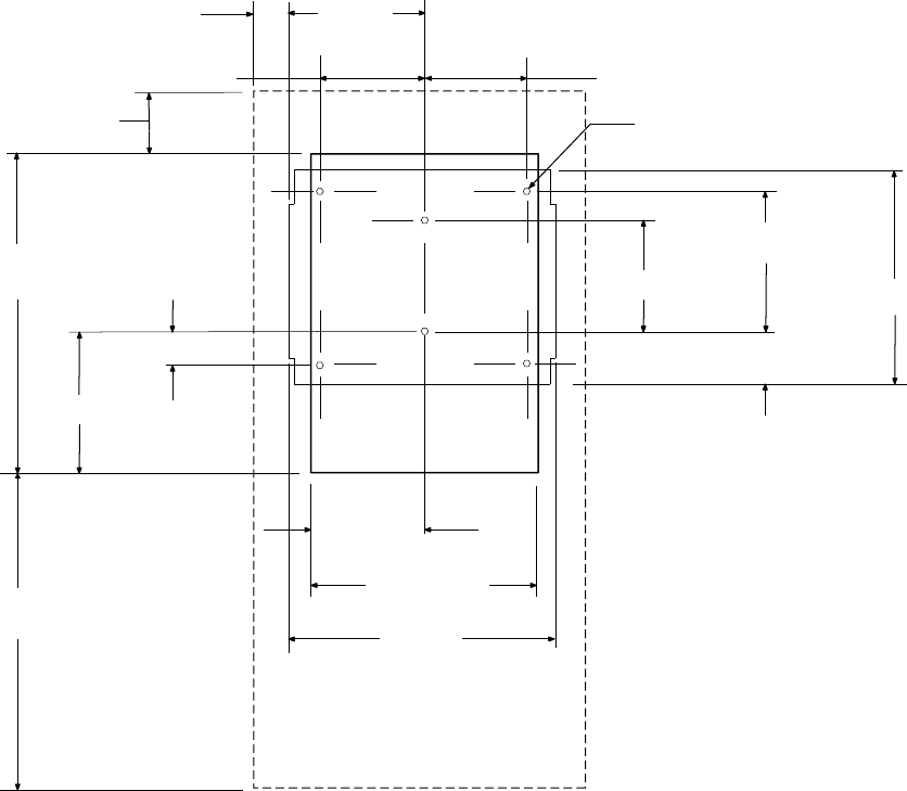
R20 1X UBS Macro B T S Hardw are Installation Site v erication
Figure 2 -5 R ack footprint
ti-cdma-05689.eps
(264.50)
2X 75.00
(Clearance)
6X M12 Fasteners
(429.80)
(284.20)
(700.00)
700.00
(Clearance) (529.00)
(447.00)
(223.50)
(101.60)
2X 209.55 +/- 0.40
226.60 +/- 0.40
2X 277.40 +/- 0.40
2X 50.80 +/- 0.40
150.00
(Clearance)
2X 209.55 +/- 0.40
FRONT
Measurements are in mm.
C
L
68P09283A62 -3 2 -19
PRELIMINARY A UG 2007

T ask 1: Installing RGPS Head Chapter 2: UBS Macro B T S Installation Procedure
Task 1: Installing RGPS Head■■■■■■■■■■■■■■■■■■■■■■■■■■■■■■■■■■■■■■■■■■■■■■■■■■■■■■■■■■■■■■
■
■
Objective
The objective of this procedure is to install the optional Remote GPS (RGPS) head and cables
(NN and AA). The site configuration/characteristics determines whether an RGPS head and
cables are to be installed.
Any of the following RGPS heads may be used:
•STLN6594 (Motorola part number)
•0186012H04 (Motorola part number)
Cable NN works with any of the above listed RGPS heads.
RGPS head installation
Required items
The following tools are required:
•Adjustable torque ratchet with metric socket set
•Flat head screwdriver
•Lightning Arrestor (Motorola part number CGDSO971017AA1 or equivalent)
T able 2 -9 gives a list of the cables for connecting the RGPS head.
Table 2 -9 List of required cables for RGPS head installation
Cable Quantity
Part Number Description
AA
One SGKN4430
(3086433H14)
15 pin D -connector on one end and loose wires
on the other end.
NN
Only one
of the
following:
3086039H10
3086039H11
3086039H12
3086039H13
3086039H14
RGPS cable, 15 m (50 ft); part of Option T472AG
RGPS cable, 38 m (125 ft); part of Option T472AH
RGPS cable, 76 m (250 ft); part of Option T472AJ
RGPS cable, 152 m (500 ft); part of Option T472AK
RGPS cable, 304 m (1000 ft); part of Option
T472AL
2 -20 68P09283A62 -3
PRELIMINARY A UG 2007
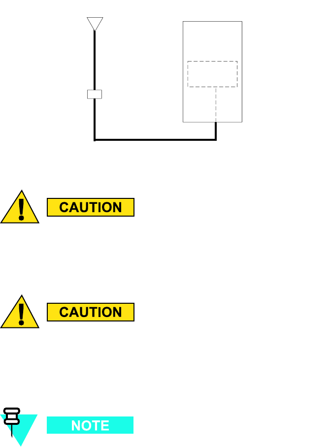
R20 1X UBS Macro B T S Hardw are Installation T ask 1: Installing RGPS Head
Cabling diagrams
The following figures show the cabling for an RGPS head.
Figure 2 -6 RGPS cabling diagr am
ti-cdma-05700.eps
NN
AA
Remote GPS
Head
Lightning Arrestor
BTS
SSI
When wiring the Motorola P/N STLN6594 RGPS Head at a new B T S site, the Y ellow
and Y ellow/Black wires on both sides of the lightning arrestor must be disconnected
(see Figure 2 -7 and Figure 2 -8 ). Otherwise, the STLN6594 RGPS Head will be
permanently damaged.
If a Motorola P/N 0186012H04 or 0186012H03 RGPS Head at an existing B T S site
is being replaced with the Motorola P/N STLN6594 RGPS Head, the Y ellow and
Y ellow/Black wires on both sides of the lightning arrestor must be disconnected (see
Figure 2 -7 and Figure 2 -8 ). Otherwise, the STLN6594 RGPS Head will be permanently
damaged.
The Motorola P/N 0186012H04 RGPS Head will work with the Y ellow and Y ellow/black
wires disconnected or connected on both sides of the lightning arrestor .
68P09283A62 -3 2 -21
PRELIMINARY A UG 2007
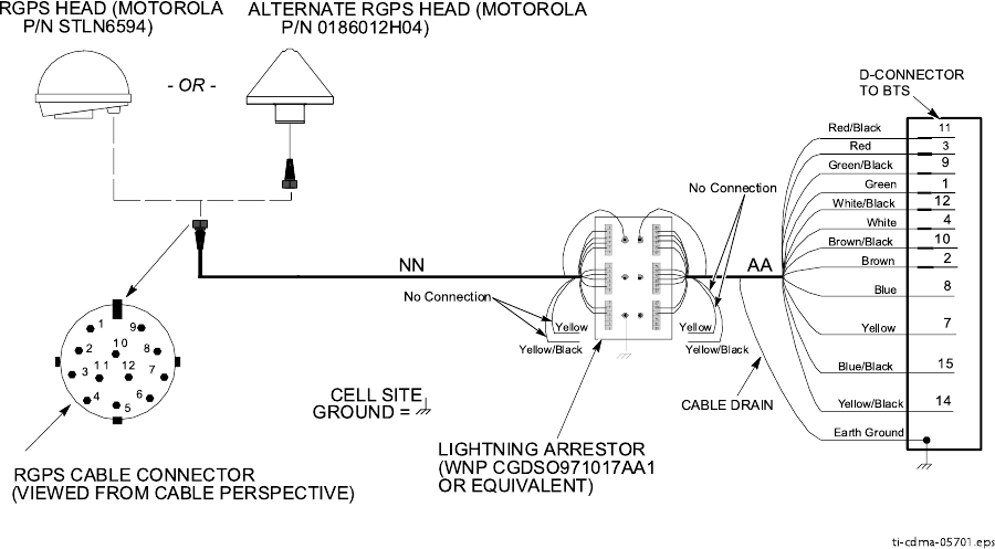
T ask 1: Installing RGPS Head Chapter 2: UBS Macro B T S Installation Procedure
Figure 2 -7 RGPS wiring
Blue/Black
Blue
Yellow/Black
Yellow
Green /Black
Green
White/Bla ck
White
Brown/Black
Brown
1
2
3
45
6
7
8
9
10
1 1 12
Earth Groun d
RGPS C ABLE CO NNECTOR
(VIEWED FROM CABLE PE RSPECTIVE)
NN AA
CABLE DRAIN
LIGHTNING ARRESTOR
(WNP CGDSO971017AA 1
OR E QUIVALENT)
D-CONNECTOR
TO BTS
1
14
10
2
4
12
7
8
15
9
ALTERN ATE RGPS HEAD (MOTOR OLA
P/N 0186012H04)
CELL SITE
GRO UND =
Red
Red/Black
3
11
Yellow
Yellow/Black
Yellow
Yellow/Black
No Connection
No Connection
ti-cdma-05701.eps
RGPS H EAD (MOTORO LA
P/N STLN6594)
- OR -
2 -22 68P09283A62 -3
PRELIMINARY A UG 2007
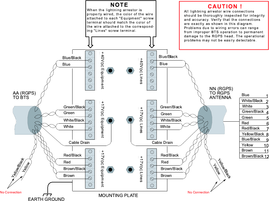
R20 1X UBS Macro B T S Hardw are Installation T ask 1: Installing RGPS Head
Figure 2 -8 RGPS lightning arrestor wiring
ti-cdma-06007.eps
Blue/Blac k
Blue
Green/Blac k
Green
White/Black
White
Red /Blac k
Yellow/Black
Yellow
Red
Brown/Blac k
Brown
Cab le Drain
Blue/Blac k
Blue
Green/B lac k
Green
White/Bla ck
White
Red/Blac k
Red
Brown/Black
Brown
Cable Drain
+40VDC Line s +17VDCLines +1 7VDC Lin e s
+17 VDCEquipm e nt+17 VDCEquipme nt+ 40VDC Eq uipm e nt
NO TE
NN (RGPS )
TO RGPS
ANTENNA
EARTH GROUN D MOUNTING PL ATE
Blue/Blac k
Blue
Yellow/Blac k
Yellow
Green/B lac k
Green
White/Blac k
White
Red/Blac k
Red
Brown/Black
Brown
1
2
3
4
5
6
7
8
9
10
11
12
No Connection No Connec tion
Wh e n t h e lig h tn in g a rre s to r is
p ro p e rly wire d, th e c o lo r o f the wire
a tta che d to e a c h "Equip m e nt" s c re w
te rm ina l s h o u ld ma t c h th e colo r o f
th e w ire a tta che d to th e corre s p o n d -
ing "Lin e s " s c re w te rmin a l.
AA (RGP S)
TO BTS
CAUTIO N !
All lig h tn in g a rre s to r wire c o n n e c tio n s
s hould be th o ro u g h ly in s p e cte d fo r in te grity
a nd a ccura cy. Ve rify th a t th e c o n n e c tio n s
a re e xa c tly a s s hown in th is dia gra m.
P ro b le m s due to wirin g e rro rs c a n ra n g e
fro m im p ro p e r BTS o p e ra tio n to pe rma n e n t
d a ma g e to the R G P S h e a d . The o p e ra tio n a l
p ro b le m s m a y n o t b e e a s ily d e te cta b le .
Yellow/Black
Yellow
Mounting diagrams
Figure 2 -9 and Figure 2 -10 show the mounting details for the RGPS heads.
68P09283A62 -3 2 -23
PRELIMINARY A UG 2007
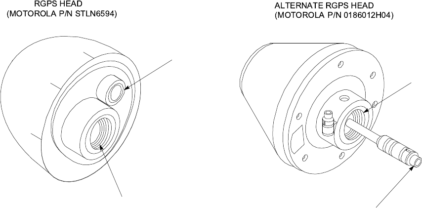
T ask 1: Installing RGPS Head Chapter 2: UBS Macro B T S Installation Procedure
Figure 2 -9 RGPS heads
ti-cdma-05702.eps
THREADED MOUNT
ADAPTER
THREADED MOUNT
ADAPTER 12-PIN DEUTSCH
TYPE MMP CONNECTOR
12-PIN DEUTSCH
TYPE MMP CONNECTOR
ALTERNATE RGPS HEAD
(MOTOROLA P/N 0186012H04)
RGPS HEAD
(MOTOROLA P/N STLN6594)
2 -24 68P09283A62 -3
PRELIMINARY A UG 2007
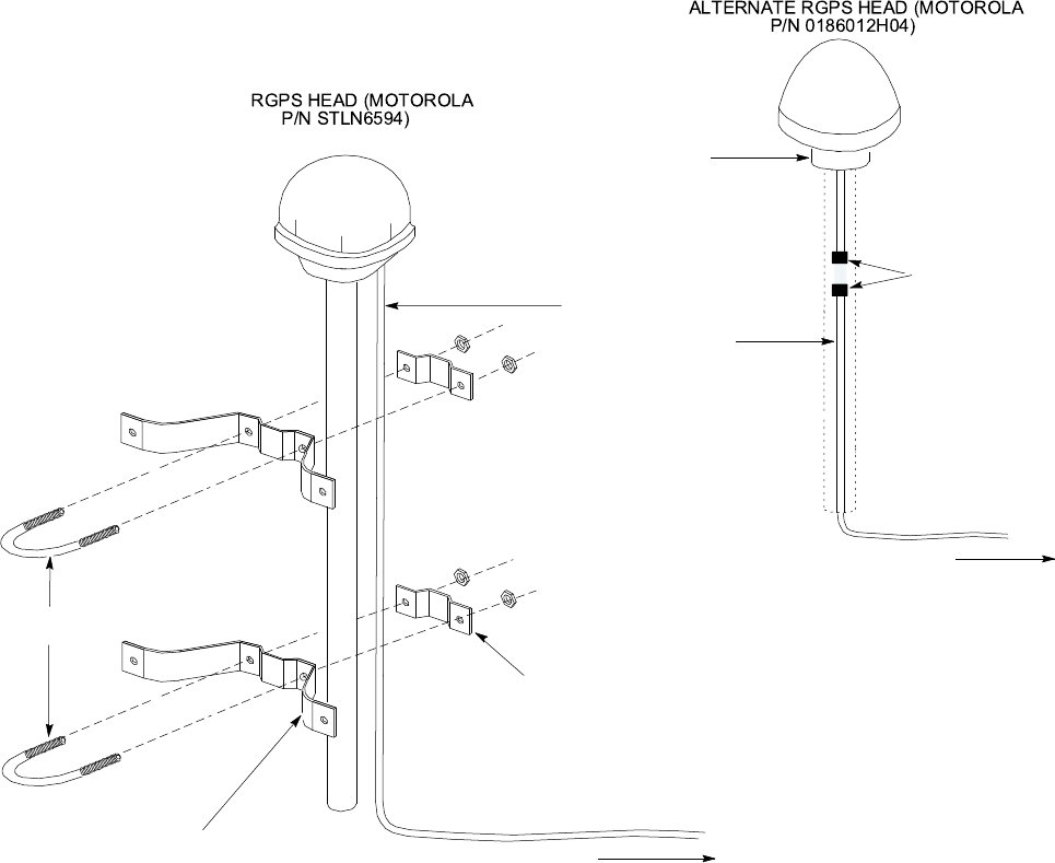
R20 1X UBS Macro B T S Hardw are Installation T ask 1: Installing RGPS Head
Figure 2 -10 Installing the RGPS head
ti-cdma-05740.eps
WALL MOUNTING
BRACKETS (2)
CLAMP BRACKETS (2)
U-BOLTS
CABLE TO LIGHTNING
ARRESTOR (CABLE NN)
RGPS HEAD WITH
12 PIN MALE
CONNECTOR
MATING
CONNECTORS
RGPS INTERFACE
CABLE WITH 12 PIN
FEMALE CONNECTOR
ON ONE END AND
UNTERMINATED WIRE
ON OTHER END
CABLE TO LIGHTNING
ARRESTOR (CABLE NN)
ALTERN ATE RGPS HEAD (MOTOR OLA
P/N 0186012H04)
RGPS H EAD (MOTORO LA
P/N STLN6594)
Cable pinout
Figure 2 -11 shows the connector pins on cables AA and NN . T able 2 -10 gives the pinout for
cable AA and NN and signal names.
68P09283A62 -3 2 -25
PRELIMINARY A UG 2007
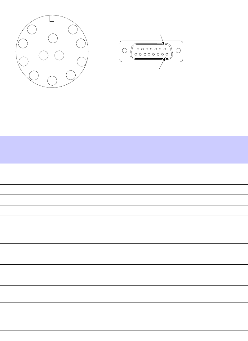
T ask 1: Installing RGPS Head Chapter 2: UBS Macro B T S Installation Procedure
Figure 2 -11 Connector pin numbering for cables NN and AA
ti-cdma-00047.eps
1
2
3
4
5
6
7
8
9
10
11 12
CONNECTOR FOR
CABLE NN
PIN 1
CONNECTOR FOR
CABLE AA
PIN 9
Table 2 -10 Pinout for cables NN and AA
Cable NN (12-cond) Cable AA (12-cond)
Pin
(12-pins)
Signal W ire Color
Pin
(15-pins)
Signal
9
DC Ground 1 Blue-Black
15 RGPS Return
1 P ower 1
Blue
8
RGPS +27 V Supply
8
Not Used Y ellow-Black
14
Not Used
10
Not Used Y ellow
7
Not Used
4
Transmit P ort (-) Green-Black
9
DA T A (-) From Head
5
Transmit P ort (+)
Green 1
DA T A (+) From
Head
2
Receive P ort (-) White-Black
12
DA T A (-) T o Head
3
Receive P ort (+) White
4
DA T A (+) T o Head
7
Not Connected Red-Black
11
TDR Ground
6
Not Connected Red
3
TDR (+)
12
PPS Timing (-) Brown-Black
10
SYNC (-) From Head
11
PPS Timing (+)
Brown
2
SYNC (+) From
Head
Cable Drain
(Shield)
13
Ground
5, 6
Not Connected
W ire colors are the same for both cables.
2 -26 68P09283A62 -3
PRELIMINARY A UG 2007
R20 1X UBS Macro B T S Hardw are Installation T ask 1: Installing RGPS Head
Procedure
The procedure to install the RGPS antenna is as follows:
Procedure 2 -1 Procedure to install an RGPS head
1
Determine the mounting location for the RGPS head.
The structure of the w all should be v eried b y a qualied structur al
engineer . Mounting the RGPS head and hardw are to an inadequate
w all structure and/or using inadequate installation methods can
result in serious personal injury .
2
Use the appropriate mounting bolts for the mounting surface and install the
two wall mounting brackets. Refer to Figure 2-10 .
3
Route the 12-pin Deutsch (that is, circular) connector end of the RGPS cable
(cable NN) to the RGPS head.
4
Connect the RGPS cable (cable NN) connector to the RGPS head 12-pin
circular connector as shown in Figure 2-7 and Figure 2-10 . Tighten the
spinning flange on the connector a quarter turn, to secure the connection.
5
Insert the RGPS mounting pipe into the threaded mount of the RGPS head
and carefully tighten it manually .
6
Install the RGPS mounting pipe into the mounting brackets as shown in
Figure 2-10 . Tighten the U -bolt clamps to secure the assembly . F or the
STLN6594 RGPS Head, tape or tie-wrap the cable to the mounting pipe.
7
Route the free end of the BTS RGPS cable (cable NN) to the RGPS
cable lightning arrester . Remove any excess cable length and strip off
approximately 15 cm of the cable outer insulation.
8
Connect the twelve (12) wires and cable drain of the cable end to the
lightning arrester as shown in Figure 2-8 . Double check the lightning
arrester connections for compliance as displayed in Figure 2-8 .
RGPS cable AA gets connected to the UBS Macro BTS and then
routed to the RGPS cable lightning arrester during T ask 8.
68P09283A62 -3 2 -27
PRELIMINARY A UG 2007
T asks 2 -3: Installing R ack & Ground Cable Chapter 2: UBS Macro B T S Installation Procedure
Tasks 2 -3: Installing Rack & Ground Cable■■■■■■■■■■■■■■■■■■■■■■■■■■■■■■■■■■■■■■■■■■■■■■■■■■■■■■■■■■■■■■
■
■
Objectives
The objectives of this procedure are as follows:
•Mount the rack to the floor .
•Install the ground cable (DD).
Rack requirements
The UBS Macro BTS equipment is designed to be mounted in an open standard 19–inch rack.
T o ensure proper equipment support, grounding, and easy installation, Motorola recommends
that the UBS Macro BTS equipment be mounted in one of the following applicable Motorola
racks:
•STHN4120 19–inch (1800 mm)
•STHN4121 19–inch (1400 mm)
•STHN4122 19–inch (1000 mm)
Structural engineer prerequisite
Ensure that the procedure, tools, and equipment required to mount the rack to the floor are
specified by a Structural Engineer .
2 -28 68P09283A62 -3
PRELIMINARY A UG 2007
R20 1X UBS Macro B T S Hardw are Installation T asks 2 -3: Installing R ack & Ground Cable
Required items
The following items are required:
•R ack
•10 mm socket
•T orque driver
•Flat blade screwdriver
•6 carbon steel grade 8.8 bolts M12 - customer supplied
•Other items, specified by the Structural Engineer , that are required to install the rack
•Cable DD - customer supplied ground cable, 4 A WG or larger diameter
•T wo -hole ground lug and mounting nuts - part of rack hardware kit (CGDSTB54205)
68P09283A62 -3 2 -29
PRELIMINARY A UG 2007
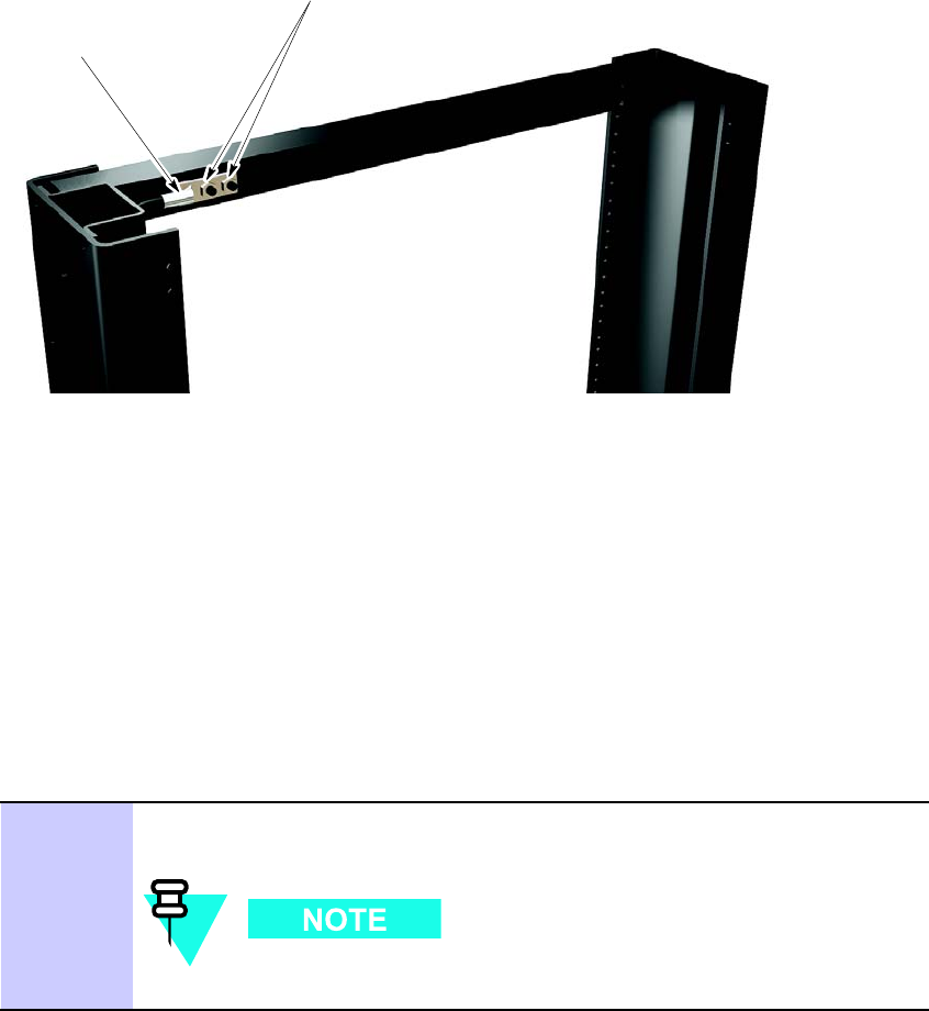
T asks 2 -3: Installing R ack & Ground Cable Chapter 2: UBS Macro B T S Installation Procedure
Location of rack earth ground terminals
Figure 2 -12 shows the location of the ground terminals on the rack.
Figure 2 -12 Location of ground terminals on a Motorola r ack
ti-cdma-05691.eps
Earth Ground
Terminal Studs
Ground Cable With
2-hole Lug Fastened
To Ground Terminals
Rack
(top/rear view, shown
partially cut away)
Procedure
Procedure 2 -2 gives the procedure for performing T asks 2 -3.
Procedure 2 -2 P erforming T asks 2 -3
1
Mount the rack to the floor using the hardware, tools and procedures
defined by the Structural Engineer .
Motorola recommends using carbon steel grade 8.8 M12 bolts.
Continued
2 -30 68P09283A62 -3
PRELIMINARY A UG 2007
R20 1X UBS Macro B T S Hardw are Installation T asks 2 -3: Installing R ack & Ground Cable
Procedure 2 -2 P erforming T asks 2 -3 (Continued)
2
Route the ground cable (cable DD) between the Master Ground Bar (MGB)
and the rack.
Ground cables must not have sharp bends.
3
Strip insulation from the frame end of cable DD .
4
A ttach the 2-hole lug to the rack -end of the cable DD .
5
A ttach the end of cable DD with the 2-hole lug to the 2 terminal studs at the
top of the rack. Using 2 nuts, 10 mm socket and ratchet, tighten the nuts to
5.65 N-m (50 inch-lb). Refer to Figure 2-12 for location of ground terminal
studs on the rack.
6
Cut cable DD to length and connect it to the Master Ground Bar .
7
V erify that the Master Ground Bar is connected to a solid earth ground.
68P09283A62 -3 2 -31
PRELIMINARY A UG 2007

T ask 4: R ack Mounting the Optional PSM Shelf Chapter 2: UBS Macro B T S Installation Procedure
Task 4: Rack Mounting the Optional PSM Shelf■■■■■■■■■■■■■■■■■■■■■■■■■■■■■■■■■■■■■■■■■■■■■■■■■■■■■■■■■■■■■■
■
■
Objectives
The objectives of this procedure are as follows:
•F or -48 V DC or 220 V AC UBS only .
Install the PSM shelf to the bottom of the rack. The site configuration/characteristics will
determine if a PSM shelf is to be installed.
•Install the appropriate, -48 V DC or 220 V AC , PSMs into PSM shelf slots 1 and 2. F or
the low capacity frame, either two -48 V DC or two 220 V AC PSMs are installed in the
shelf . The second PSM is for redundancy .
Required items
The following items are required:
•Either a -48 V DC or a 220 V AC PSM shelf (whichever is applicable)
•Either two -48 V DC or two 220 V AC PSMs (whichever is applicable)
•Eight (8) M5 x 12 mm screws for mounting the PSM shelf - these screws are packaged
with the PSM shelf
•T ape measure with millimeter scale, capable measuring up to 1200 mm or with inch scale,
capable measuring up to 48 inches; for measuring screw location heights on rack
•TORX T25 bit and driver
•T orque driver
Procedure
Procedure 2 -3 gives the procedure for performing T ask 4.
Procedure 2 -3 Procedure for T ask 4
1
Locate the bottom RU that is to be used for the installation of the PSM shelf .
2
Using a tape measure, measure mounting screw location heights on each
side of the rack. Measure from the bottom of the RU determined in step 1
(Refer to Figure 2-13 ). Mark the following screw locations:
Continued
2 -32 68P09283A62 -3
PRELIMINARY A UG 2007
R20 1X UBS Macro B T S Hardw are Installation T ask 4: R ack Mounting the Optional PSM Shelf
Procedure 2 -3 Procedure for T ask 4 (Continued)
•136 mm (5.35 inches) for PSM shelf
3
P artially insert an M5 x 12 mm screw into each location marked on the rack.
Leave the screw heads extending 7 mm out from the rack surface.
4
Remove the PSM shelf from its packaging.
5
Align the keyhole slots in the PSM shelf with the bottom screws, installed in
step 3 above (Refer to Figure 2-14 ).
6
Insert screws in the 6 open slots of the PSM shelf . Using TORX T25 driver ,
tighten all 8 PSM shelf screws to 4.77 N-m (42 in-lb).
7
PSM weighs appro ximately 5 kg. Be careful when handling the
PSM to prev ent damage to the equipment and personal injury .
Install the appropriate PSMs into PSM shelf slots 1 and 2 as follows:
1. Grasp the handle on the front panel of the PSM with one hand while
carefully supporting the bottom of the module with the other hand.
2. Properly orient the PSM and insert it into the slot.
3. Slowly slide the module into the shelf until the rear connectors are
fully seated. Make sure that the PSM is fully engaged with the shelf
backplane slot connectors.
8
Using a T25 TORX bit and torque driver , tighten the PSM captive retaining
thumbscrew to 2.37 N-m (21 in-lb).
68P09283A62 -3 2 -33
PRELIMINARY A UG 2007
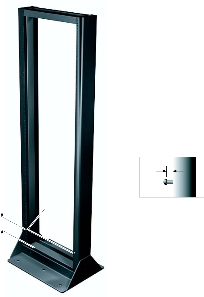
T ask 4: R ack Mounting the Optional PSM Shelf Chapter 2: UBS Macro B T S Installation Procedure
Procedural reference diagrams
The following diagrams help clarify certain steps in Procedure 2 -3 .
Figure 2 -13 Hanger screw la y out for the optional PSM shelf
136
Hanger Screw Layout for optional PSM Shelf
Hanger Screw
(Detail A)
NOTE
1. All dimensions are in millimeters
2. 1800 mm high rack shown. Dimension and hanger screw locations
are also applicable for the 1400 mm rack. ti-cdma-06011.eps
Detail A
Hanger Screw Extension
7
2 -34 68P09283A62 -3
PRELIMINARY A UG 2007
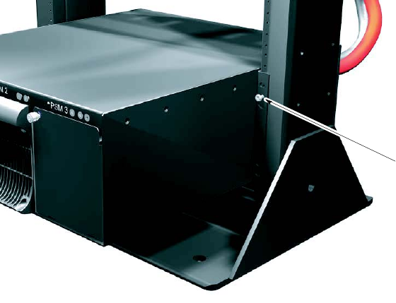
R20 1X UBS Macro B T S Hardw are Installation T ask 4: R ack Mounting the Optional PSM Shelf
Figure 2 -14 Hanging the PSM shelf
ti-cdma-05869.eps
PSM shelf keyhole
located on hanger screw
NOTE
1. A keyhole/hanger screw is located on both the right and left sides.
Both keyholes/hanger screws should be engaged at the same time.
68P09283A62 -3 2 -35
PRELIMINARY A UG 2007

T ask 5: R ack Mounting for Low -Capacit y Fr ame Chapter 2: UBS Macro B T S Installation Procedure
Task 5: Rack Mounting for Low -Capacity Frame■■■■■■■■■■■■■■■■■■■■■■■■■■■■■■■■■■■■■■■■■■■■■■■■■■■■■■■■■■■■■■
■
■
Objective
The objective of T ask 5 is to install the UBS Macro carrier strip assembly into an EIA 19 -inch
rack.
The UBS Macro carrier strip assembly contains all of the equipment required for configuring a
low -capacity , +27 V DC starter frame. The layout of the equipment on the carrier strips allows
capacity expansion of the frame.
The most common and preferred method is to install the UBS Macro carrier strip assembly into
an 1800 mm or 1400 mm high rack. This method requires that there be 600 mm of clearance on
the left and right sides of the rack.
The UBS Macro carrier strip assembly requires a minimum of 27 R ack Units (RUs) of
continuous space.
Required items
The following items are required:
•UBS Macro carrier strip assembly
•T ape measure with millimeter scale, capable measuring up to 1200 mm or with inch scale,
capable measuring up to 48 inches; for measuring screw location heights on rack
•T wenty -six (26) M5 x 12 mm screws for mounting the UBS carrier strip assembly - these
screws are included in the STGN4034 Installation Kit that is packaged with the UBS Macro
carrier strip assembly
•TORX T25 bit and driver
•T orque driver
•10 mm socket and ratchet
2 -36 68P09283A62 -3
PRELIMINARY A UG 2007
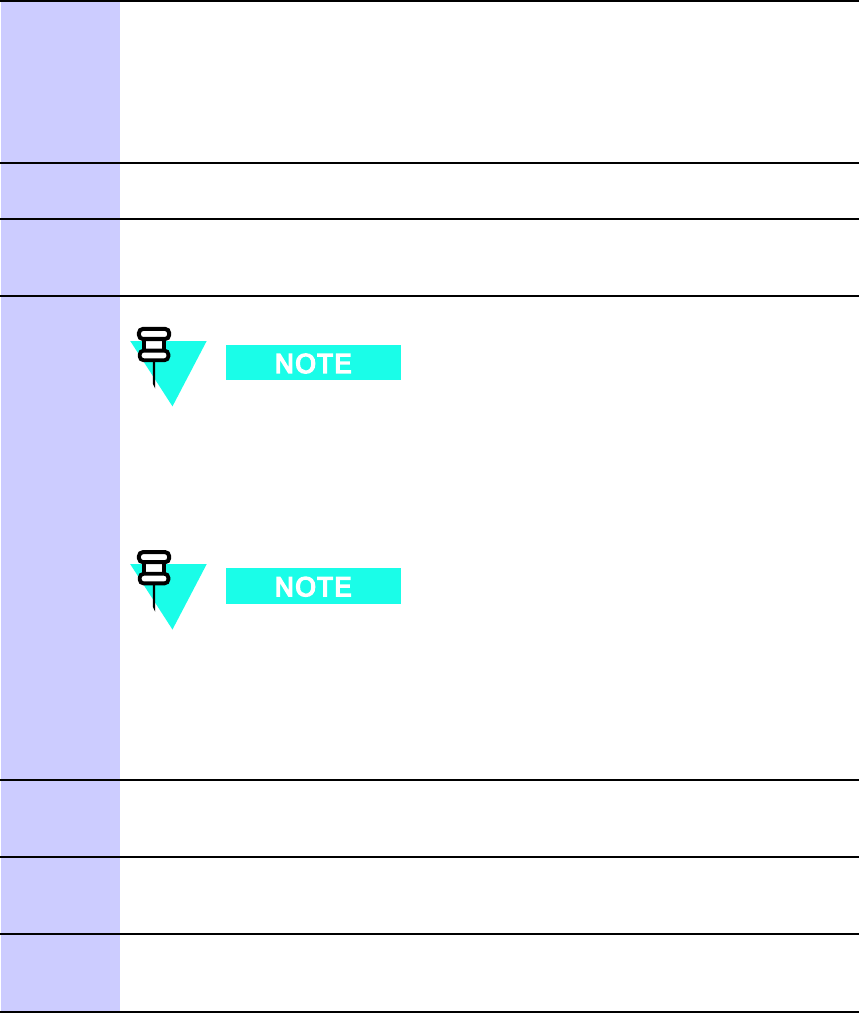
R20 1X UBS Macro B T S Hardw are Installation T ask 5: R ack Mounting for Low -Capacit y Fr ame
Procedure
Procedure 2 -4 gives the procedure for performing T ask 5.
Procedure 2 -4 R ack Mounting the Low -Capacit y , +27 V DC UBS Macro B T S Assembly
1
Using a tape measure, measure mounting hanger screw location heights on
each side of the rack (see Figure 2-15 Hanger screw layout for UBS Macro
carrier strip assembly on page 2- 39 ). Measure down from the very top of the
rack. Mark the following screw locations:
•95.25 mm (3.75 inches) for the top of the UBS Macro carrier strip
assembly
2
P artially insert an M5 x 12 mm screw into each location marked on the rack.
Leave the screw heads extending 7 mm out from the rack surface.
3
Move the pallet with the unpacked UBS Macro carrier strip assembly and
support near the rack so as to allow movement on both sides of the support
and in front of the rack. Leave the carrier strip assembly on the support.
4
The carrier strips allow four people to carefully lift the UBS Macro
carrier strip assembly off the support and onto the rack. The
assembly can also be lifted via some mechanical aid (hoist, etc.)
attached to the lifting loops on the ends of the carrier strips.
F our people, two on each side, are needed to lift the carrier strip
assembly .
Lift the UBS Macro carrier strip assembly up and off of the support and hang
it on the rack (see Figure 2-16 Lifting and hanging the carrier strip assembly
on the rack on page 2- 40 ).
5
Using the carrier strip hanger screws previously installed in the rack, align
the top carrier strip keyhole slots with the two hanger screws. Hang the
carrier strip assembly on these two screws.
6
Insert a screw in the two bottom carrier strip keyhole slots (see Figure 2-17
Carrier strip assembly keyhole screw locations on page 2- 41 ). Do not tighten
the screws in carrier strip keyhole slots.
7
Insert screws in the 22 open slots of the various shelves of the carrier strip
assembly . Using a T25 TORX driver , tighten these 22 screws to 4.77 N-m
(42 in-lb).
Continued
68P09283A62 -3 2 -37
PRELIMINARY A UG 2007

T ask 5: R ack Mounting for Low -Capacit y Fr ame Chapter 2: UBS Macro B T S Installation Procedure
Procedure 2 -4 R ack Mounting the Low -Capacit y , +27 V DC UBS Macro B T S Assembly
(Continued)
8
Using a T25 TORX driver , tighten the four screws in carrier strip keyhole
slots to 4.77 N-m (42 in-lb).
9
This step is optional and is only performed if there is
a desire to remove the carrier strips from the frame.
Remove the carrier strips from the frame as follows:
•Using a 10 mm socket and ratchet, loosen and remove the 8 nuts that
secure each carrier strip to the frame.
•Remove the carrier strip.
Procedural reference diagrams
The following diagrams help clarify certain steps in Procedure 2 -4 .
•Figure 2 -15 Hanger screw layout for UBS Macro carrier strip assembly on page 2 - 39
•Figure 2 -16 Lifting and hanging the carrier strip assembly on the rack on page 2 - 40
•Figure 2 -17 Carrier strip assembly keyhole screw locations on page 2 - 41
2 -38 68P09283A62 -3
PRELIMINARY A UG 2007
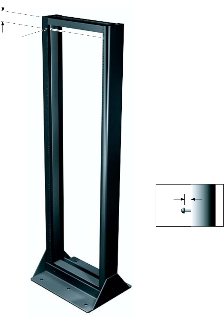
R20 1X UBS Macro B T S Hardw are Installation T ask 5: R ack Mounting for Low -Capacit y Fr ame
Figure 2 -15 shows hanger screw layout used for mounting the UBS Macro carrier strip assembly
onto a 1400 mm or 1800 mm high EIA 19 -inch rack.
Figure 2 -15 Hanger screw la y out for UBS Macro carrier strip assembly
Hanger Screw Layout for UBS
Carrier Strip Assembly
Hanger Screw
(Detail A)
NOTE
1. All dimensions are in millimeters
2. 1800 mm high rack shown. Dimension and hanger screw locations are also applicable for the 1400 mm rack ti-cdma-06012.eps
Detail A
Hanger Screw Extension
95.25
7
68P09283A62 -3 2 -39
PRELIMINARY A UG 2007
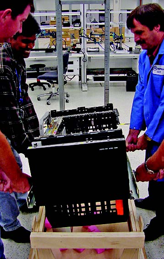
T ask 5: R ack Mounting for Low -Capacit y Fr ame Chapter 2: UBS Macro B T S Installation Procedure
Figure 2 -16 shows four people lifting and hanging the UBS Macro carrier strip assembly on
the rack.
Figure 2 -16 Lifting and hanging the carrier strip assembly on the r ack
ti-cdma-06386.eps
UBS Macro BTS Handles
2 -40 68P09283A62 -3
PRELIMINARY A UG 2007
R20 1X UBS Macro B T S Hardw are Installation T ask 5: R ack Mounting for Low -Capacit y Fr ame
Figure 2 -17 shows the keyhole screw locations in a rack mounted UBS Macro carrier strip
assembly .
Figure 2 -17 Carrier strip assembly k eyhole screw locations
ti-cdma-05870.eps
Bottom keyhole of carrier strip
located on hanger screw
NOTE
1. Another carrier strip keyhole/hanger screw is located at the top of the right side carrier strip/rack rail.
The left side carrier strip/rack rail has a top and bottom keyholes/hanger screws at the same heights as the right side.
All four keyholes/hanger screws should be engaged at the same time.
68P09283A62 -3 2 -41
PRELIMINARY A UG 2007

T ask 6: Expanding the Low -capacit y Fr ame Chapter 2: UBS Macro B T S Installation Procedure
Task 6: Expanding the Low -capacity Frame■■■■■■■■■■■■■■■■■■■■■■■■■■■■■■■■■■■■■■■■■■■■■■■■■■■■■■■■■■■■■■
■
■
If the initial UBS Macro BTS installation is for a low -capacity frame configuration,
skip this task and go to T ask 7: Cabling the Optional PSM Shelf on page 2 - 43 .
P erform this task only if the initial UBS Macro BTS installation is for a mid -capacity
frame configuration.
Objective
The objective of T ask 6 is to install the additional equipment required to expand the UBS Macro
BTS low -capacity starter/expansion frame to the mid -capacity frame configuration.
Currently a UBS Macro BTS low -capacity starter/expansion frame can only be
expanded to mid -capacity . In the future, the low -capacity starter/expansion frames
and mid -capacity frames will be expandable to high -capacity .
Procedure
Go to Chapter 3 Low -to -Mid Capacity Frame Expansion Procedures and perform all of the
applicable procedures for expanding the low -capacity UBS Macro BTS starter/expansion frame
to the mid -capacity frame configuration.
A fter all of the additional expansion equipment is installed, go to T ask 7: Cabling the Optional
PSM Shelf on page 2 - 43 and continue performing the remaining tasks in sequential order .
2 -42 68P09283A62 -3
PRELIMINARY A UG 2007

R20 1X UBS Macro B T S Hardw are Installation T ask 7: Cabling the Optional PSM Shelf
Task 7: Cabling the Optional PSM Shelf■■■■■■■■■■■■■■■■■■■■■■■■■■■■■■■■■■■■■■■■■■■■■■■■■■■■■■■■■■■■■■
■
■
Objectives
The objectives of this procedure are as follows:
•F or -48 V DC or 220 V AC UBS only .
Connect the +27 V DC power output cable from the rear of the PSM shelf to the +27 V DC
power input cable on the rear of the PDU .
•F or -48 V DC or 220 V AC UBS only
Connect the 50 -conductor cable (supplied with PSM shelf) between the PSM shelf front
panel ALARM/CONTROL connector and S SI front panel PSM connector .
Required items
The following items are required:
•50 -conductor cable (supplied with PSM shelf)
•Flat blade screw driver
Procedure
Procedure 2 -5 gives the procedure for performing T ask 7.
Procedure 2 -5 Procedure for T ask 7
1
Connect the +27 V DC power output cable from the rear of the PSM shelf
to the +27 V DC power input cable on the rear of the PDU . Mate Orange
connectors together .
2
Connect the 50-conductor cable (supplied with PSM shelf) between the PSM
shelf front panel ALARM/CONTROL connector and S SI front panel PSM
connector . Refer to Figure 2-3 and Figure 2-4 for the connector locations on
the PSM shelf front panel and on the S SI.
68P09283A62 -3 2 -43
PRELIMINARY A UG 2007

T asks 8 -9: Connecting TX/RX Antennas Chapter 2: UBS Macro B T S Installation Procedure
Tasks 8 -9: Connecting TX/RX Antennas■■■■■■■■■■■■■■■■■■■■■■■■■■■■■■■■■■■■■■■■■■■■■■■■■■■■■■■■■■■■■■
■
■
Objectives
The objectives of performing T asks 8 -9 are as follows:
•Install the external antenna cables to the Integrated Duplexer RX Filters (IDRFs).
•Install terminators on the IDRFs.
The site configuration/characteristics determines the IDRF usage.
Required items
The following items are required:
•External TX and RX 50 Ohm coaxial cables with type N connectors (customer supplied)
•0.25 W , 50 Ohm, SMA -type male terminators (customer supplied) for unused directional
coupler port connectors
•50 W N -type male terminator (customer supplied) for unused TX/RX connectors
•SMA breakover wrench
•19 mm open–end hex wrench (N–type connector)
Location of antenna connectors
The top view of Figure 2 -1 and Figure 2 -2 show the location of the UBS Macro BTS antenna
connectors on the top of the IDRF .
Procedure
The procedure for performing T asks 8 -9 is as follows.
Procedure 2 -6 Procedure for T asks 8 -9
1
Route the customer supplied TX/RX main and RX diversity antenna cables
to the top of the Integrated Duplexer RX Filters (IDRFs), located at the
top of the frame.
Continued
2 -44 68P09283A62 -3
PRELIMINARY A UG 2007

R20 1X UBS Macro B T S Hardw are Installation T asks 8 -9: Connecting TX/RX Antennas
Procedure 2 -6 Procedure for T asks 8 -9 (Continued)
2
Connect each antenna cable to the corresponding IDRF type N connector .
Refer to Figure 2-1 or Figure 2-2 , whichever is applicable, for the location of
the UBS Macro BTS antenna connectors on the top of the IDRF . Using a 19
mm open–end hex wrench, tighten the cable connectors to 4.3 N-m (38 in-lb).
The IDRFs are not labeled for a sector . T o determine the sector
for each IDRF , look at the color code of the XMI TX and RX cables
connected to the bottom of the IDRF . Refer to T able 2-2 for the
mapping of the cable color to the sector (Red = sector 1, Blue =
sector 2, Y ellow = sector 3). The sectors can also be determined
by tracing those XMI cables back to the XMI TX and RX ports,
which are labeled as TX1 and RX1 for sector 1, TX2 and RX2 for
sector 2, and TX3 and RX3 for sector 3.
3
Connect customer supplied 0.25 W , 50 Ohm, SMA-type terminators to any
unused directional coupler port connectors on the top of the IDRFs.
4
F or any unused TX/RX connector on an IDRF , install a 50 W N-type
terminator (customer supplied).
68P09283A62 -3 2 -45
PRELIMINARY A UG 2007

T asks 10 -13: Connecting RGPS , Spans, Customer Alarms Chapter 2: UBS Macro B T S Installation Procedure
Tasks 10 -13: Connecting RGPS, Spans, Customer
Alarms
■■■■■■■■■■■■■■■■■■■■■■■■■■■■■■■■■■■■■■■■■■■■■■■■■■■■■■■■■■■■■■
■
■
Objectives
The S SI pro vides only secondary surge protection for the RGPS and T1/E1 span
connections. The customer is responsible for pro viding primary surge protection.
The objectives of performing T asks 10–13 are as follows:
•Install RGPS cable (AA) between the RGPS cable lightning arrester and the UBS Macro
BTS .
•Install T1/E1 balanced Span I/O cable (W) between the UBS Macro BTS and the site span
line interconnect equipment.
•Install E1 unbalanced Span I/O coaxial cables (customer supplied) between the UBS Macro
BTS and the site span line interconnect equipment.
•Install Customer Alarm Input/Output (IP/OP) cables (X) between the UBS Macro BTS and
the Customer IP/OP interconnect equipment.
The site configuration/characteristics determines whether the cables in T asks 10 -13 are to be
installed.
Cabling options
The site characteristics determine the use of cables AA, W and X.
The RGPS cable (AA) is optional and used only when the optional RGPS head is used.
The T1/E1 balanced Span I/O cable (W) can carry up to 8 spans, but the UBS Macro BTS
currently supports only up to 4 spans. This is also true for E1 unbalanced Span I/O coaxial
cables (customer supplied).
F or Span I/O cable (W), the minimum size of span line wires is 26 A WG .
The usage and quantity of Customer Alarm Input/Output (IP/OP) cables (X) is determined by the
customer .
2 -46 68P09283A62 -3
PRELIMINARY A UG 2007
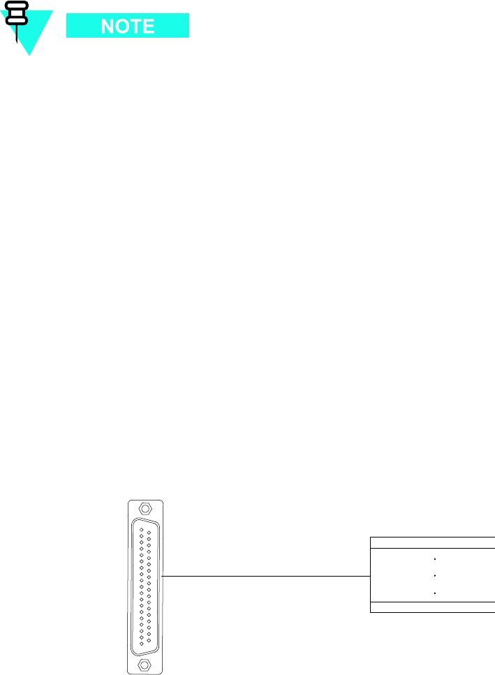
R20 1X UBS Macro B T S Hardw are Installation T asks 10 -13: Connecting RGPS , Spans, Customer Alarms
Required items
The following items are required:
•Cable AA - P art number 3086433H12
•Cable W - P art number CGDS19797321
•Cable X - P art number CGDS19797321
All S SI cable connectors with jack -screws require a flat -blade driver and should be
tightened to 1.02 N -m (9 in -lb).
Location of cables AA, W and X
Figure 2 -3 S SI front panel connectors on page 2 - 9 shows the connector locations on the front
panel of the S SI for: RGPS cable (AA), T1/E1 balanced span line cable (W), E1 unbalanced span
line coaxial cables, and customer alarm cable (X).
The optional RGPS cable (AA) has a 15 -pin D -connector on one end that connects to the RGPS
connector , located on the front of the S SI. The other cable end has loose wires. This end is
routed to the RGPS lightning arrester , where the wires connect. Refer to Figure 2 -6 through
Figure 2 -11 ,T able 2 -9 and T able 2 -10 for RGPS cable (AA) details.
Details for cables (W) and (X ) are provided in this task section.
Balanced T1/E1 cable (W) details
Figure 2 -18 and T able 2 -11 show the pin and signal information for cable W .
Figure 2 -18 T1/E1 balanced span line cable (W) pin numbering
ti-cdma-05692.eps
LOOSE WIRES, NO CONNECTOR
37-Pin-Type
(Male)
1
19 37
20
68P09283A62 -3 2 -47
PRELIMINARY A UG 2007

T asks 10 -13: Connecting RGPS , Spans, Customer Alarms Chapter 2: UBS Macro B T S Installation Procedure
F or E1 unbalanced 75 -Ohm BNC connector locations and labeling on the daughter card, refer to
Figure 2 -3 S SI front panel connectors on page 2 - 9 .
T able 2 -11 also shows the correlation between spans and the E1 unbalanced Span I/O coaxial
BNC connectors.
Table 2 -11 T1/E1 I/O cable W (span) signal and pin information
T1/E1 Balanced Span 36-Cond
Shielded T wisted Pair Cable (W)
37-Pin D-Sub Connector
E1 Unbalanced
75-Ohm Coaxial Cable
BNC Connection
(RING is GND/shield)
Span
number
Signal name
Pin
W ire Color
TX1_TIP 1
White/Blue
TX1_RING 20
Blue/White
TX1
RX1_TIP 12
Black/Orange
1
RX1_RING 30
Orange/Black
RX1
TX2_TIP 2
White/Orange
TX2_RING 21
Orange/White
TX2
RX2_TIP 13
Black/Green
2
RX2_RING 31
Green/Black
RX2
TX3_TIP 3
White/Green
TX3_RING 22
Green/White
TX3
RX3_TIP 14
Black/Brown
3
RX3_RING 32
Brown/Black
RX3
TX4_TIP 4
White/Brown
TX4_RING 23
Brown/White
TX4
RX4_TIP 15
Black/Gray
4
RX4_RING 33
Gray/Black
RX4
TX5_TIP 5
White/Gray
TX5_RING 24
Gray/White
TX5
RX5_TIP
16
Y ellow/Blue
5
RX5_RING 34
Blue/Y ellow
RX5
TX6_TIP 6
Red/Blue
TX6_RING 25
Blue/Red
TX6
RX6_TIP 17
Y ellow/Orange
6
RX6_RING 35
Orange/Y ellow
RX6
Continued
2 -48 68P09283A62 -3
PRELIMINARY A UG 2007

R20 1X UBS Macro B T S Hardw are Installation T asks 10 -13: Connecting RGPS , Spans, Customer Alarms
Table 2 -11 T1/E1 I/O cable W (span) signal and pin information (Continued)
T1/E1 Balanced Span 36-Cond
Shielded T wisted Pair Cable (W)
37-Pin D-Sub Connector
E1 Unbalanced
75-Ohm Coaxial Cable
BNC Connection
(RING is GND/shield)
Span
number
Signal name
Pin
W ire Color
TX7_TIP 7
Red/Orange
TX7_RING 26
Orange/Red
TX7
RX7_TIP
18
Y ellow/Green
7
RX7_RING 36
Green/Y ellow
RX7
TX8_TIP 8
Red/Green
TX8_RING 27
Green/Red
TX8
RX8_TIP 19
Y ellow/Brown
8
RX8_RING 37
Brown/Y ellow
RX8
Ground
9
Red/Brown
Ground
28
Brown/Red
Not
Connected
10
Ground
11
Black/Blue
Ground
29
Blue/Black
Customer alarm input/output (IP/OP) cable (X) details
Alarm connectors
There are two ALARM connectors on the UBS Macro S SI:
•CUSTOMER IP 1 -12 OP 1 -4 connector
•CUSTOMER IP 13 -24 OP 5 -8 connector
Each ALARM connector provides 12 inputs and 4 outputs. A total of 24 inputs and 8 outputs are
available.
68P09283A62 -3 2 -49
PRELIMINARY A UG 2007
T asks 10 -13: Connecting RGPS , Spans, Customer Alarms Chapter 2: UBS Macro B T S Installation Procedure
Function
ALARM connectors provide for Customer Defined Alarm Inputs and Outputs. The customer can
connect BTS site alarm input sensors and output devices to the UBS Macro BTS , thus providing
alarm reporting of active sensors as well as controlling output devices.
The S SI detects signals from customer input sensors and reports the detected signals to the
DMI controller , which in turn reports the detected alarm to the OMC -R, where it is displayed as
defined by the customer .
The S SI also provides switched relay contacts to customer output devices. The S SI controls
relay contacts according to output control signals from the DMI controller , in response to
customer defined commands entered at the OMC -R.
Input connections
Each input consists of a wire/pin pair (that is, input/Gnd). T o ensure proper operation, each
pair to be used must be connected to an external sensor that provides a dry -contact closure.
The customer sensor output connects between an optically isolated 5 V DC signal and an
isolated return.
F or an OPEN circuit (logic 0) between pins:
•There is 10 K Ohms or greater across the input pair .
•The signal to ground voltage is +5 V DC .
F or a CLOSED circuit (logic 1) between pins:
•There is 1 K Ohms or less across the input pair .
•The signal to ground current is a maximum of 9 mA.
Either of the above states can be defined by the customer in system software as an alarm
condition.
Output connections
Each output consists of 3 -wires/pins:
•COM
•NC
•NO
The customer output device control inputs connect between the common (COM) and either the
normally closed (NC) or normally open (NO) contacts of a relay . The NC and NO state for relay
contacts occurs when the relay coil is not energized.
Relay contacts are load rated for a maximum of 1 A at 24 V DC and 0.5 A at 50 V DC .
The toggling of relay contacts to the opposite state is controlled by system software.
Pins and signals
Figure 2 -19 ,T able 2 -12 and T able 2 -13 show the pin and signal information for cable X.
2 -50 68P09283A62 -3
PRELIMINARY A UG 2007
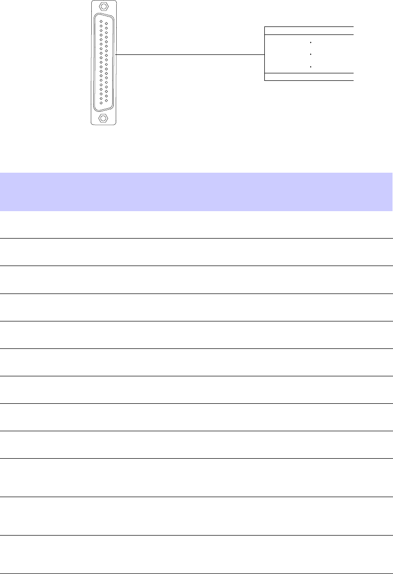
R20 1X UBS Macro B T S Hardw are Installation T asks 10 -13: Connecting RGPS , Spans, Customer Alarms
Figure 2 -19 Customer alarm cable (X) pin numbering
ti-cdma-05692.eps
LOOSE WIRES, NO CONNECTOR
37-Pin-Type
(Male)
1
19 37
20
Table 2 -12 Customer alarm cable (X) pinout for customer IP 1 -12 OP 1 -4
37-Pin
D-Sub Pin
number
Signal
Description
W ire Color
37Pin
D-Sub Pin
number
Signal
Description
W ire Color
1 Customer
Input 1
White/Blue
20
Input 1 Gnd Blue/White
2 Customer
Input 2
White/Orange
21
Input 2 Gnd Orange/White
3 Customer
Input 3
White/Green
22
Input 3 Gnd Green/White
4 Customer
Input 4
White/Brown
23
Input 4 Gnd Brown/White
5
Customer
Input 5
White/Gray
24
Input 5 Gnd Gray/White
6 Customer
Input 6
Red/Blue
25
Input 6 Gnd Blue/Red
7
Customer
Input 7
Red/Orange
26
Input 7 Gnd Orange/Red
8 Customer
Input 8
Red/Green
27
Input 8 Gnd Green/Red
9 Customer
Input 9
Red/Brown
28
Input 9 Gnd Brown/Red
10
Not
Connected
29 Customer
Output NC
1
Blue/Black
11 Customer
Output
NO 1
Black/Blue
30 Customer
Output
Common 1
Orange/Black
12 Customer
Output
NO 2
Black/Orange
31 Customer
Output
Common 2
Green/Black
Continued
68P09283A62 -3 2 -51
PRELIMINARY A UG 2007

T asks 10 -13: Connecting RGPS , Spans, Customer Alarms Chapter 2: UBS Macro B T S Installation Procedure
Table 2 -12 Customer alarm cable (X) pinout for customer IP 1 -12 OP 1 -4 (Continued)
37-Pin
D-Sub Pin
number
Signal
Description
W ire Color
37Pin
D-Sub Pin
number
Signal
Description
W ire Color
13 Customer
Output
NC 2
Black/Green
32 Customer
Output NC
3
Brown/Black
14 Customer
Output
NO 3
Black/Brown
33 Customer
Output
Common 3
Gray/Black
15 Customer
Output
NO 4
Black/Gray
34 Customer
Output
Common 4
Blue/Y ellow
16 Customer
Output
NC 4
Y ellow/Blue
17 Customer
Input 10
Y ellow/Orange
35 Input 10
Gnd
Orange/Y ellow
18 Customer
Input 11
Y ellow/Green
36 Input 11
Gnd
Green/Y ellow
19 Customer
Input 12
Y ellow/Brown
37 Input 12
Gnd
Brown/Y ellow
Table 2 -13 Customer alarm cable (X) pinout for customer IP 13 -24 OP 5 -8
37-Pin
D-Sub Pin
number
Signal
Description
W ire Color
37-Pin
D-Sub Pin
number
Signal
Description
W ire Color
1 Customer
Input 13
White/Blue
20 Input 13
Gnd
Blue/White
2 Customer
Input 14
White/Orange
21 Input 14
Gnd
Orange/White
3 Customer
Input 15
White/Green
22 Input 15
Gnd
Green/White
4 Customer
Input 16
White/Brown
23 Input 16
Gnd
Brown/White
5
Customer
Input 17
White/Gray
24 Input 17
Gnd
Gray/White
6 Customer
Input 18
Red/Blue
25 Input 18
Gnd
Blue/Red
7
Customer
Input 19
Red/Orange
26 Input 19
Gnd
Orange/Red
8 Customer
Input 20
Red/Green
27 Input 20
Gnd
Green/Red
9 Customer
Input 21
Red/Brown
28 Input 21
Gnd
Brown/Red
Continued
2 -52 68P09283A62 -3
PRELIMINARY A UG 2007

R20 1X UBS Macro B T S Hardw are Installation T asks 10 -13: Connecting RGPS , Spans, Customer Alarms
Table 2 -13 Customer alarm cable (X) pinout for customer IP 13 -24 OP 5 -8
(Continued)
37-Pin
D-Sub Pin
number
Signal
Description
W ire Color
37-Pin
D-Sub Pin
number
Signal
Description
W ire Color
10
Not
Connected
29 Customer
Output NC 5
Blue/Black
11 Customer
Output NO 5
Black/Blue
30 Customer
Output
Common 5
Orange/Black
12 Customer
Output NO 6
Black/Orange
31 Customer
Output
Common 6
Green/Black
13 Customer
Output NC 6
Black/Green
32 Customer
Output NC 7
Brown/Black
14 Customer
Output NO 7
Black/Brown
33 Customer
Output
Common 7
Gray/Black
15 Customer
Output NO 8
Black/Gray
34 Customer
Output
Common 8
Blue/Y ellow
16 Customer
Output NC 8
Y ellow/Blue
17 Customer
Input 22
Y ellow/Orange
35 Input 22
Gnd
Orange/Y ellow
18 Customer
Input 23
Y ellow/Green
36 Input 23
Gnd
Green/Y ellow
19 Customer
Input 24
Y ellow/Brown
37 Input 24
Gnd
Brown/Y ellow
Procedure
P erform T asks 10 -13 as given in Procedure 2 -7 .
Procedure 2 -7 Procedure for T asks 10 -13
1
Connect the 15-pin D -connector end of cable (AA) to the RGPS connector on
the front of the S SI. Refer to Figure 2-3 for the connector location on the S SI.
2
Route the loose end of cable (AA) to the RGPS lightning arrester and connect
the wires there. Refer to Figure 2-6 through Figure 2-11 ,T able 2-9 and
T able 2-10 .
3
F or T1/E1 balanced span line connections, go to step 4 . F or E1 unbalanced
span line connections, go to step 7 .
Continued
68P09283A62 -3 2 -53
PRELIMINARY A UG 2007
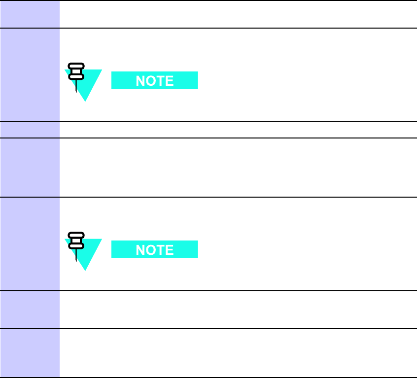
T asks 10 -13: Connecting RGPS , Spans, Customer Alarms Chapter 2: UBS Macro B T S Installation Procedure
Procedure 2 -7 Procedure for T asks 10 -13 (Continued)
4
Connect the 37-pin D -connector end of cable (W) to the SP AN connector on
the front of the S SI. Refer to Figure 2-3 for the connector location on the S SI.
5
Route the loose end of cable (W) to the customer span line interconnect
equipment and connect the wires. Refer to T able 2-11 .
The UBS Macro BTS currently supports only up to 4 spans.
6
Go to step 9 .
7
Connect E1 unbalanced Span I/O coaxial cables (customer supplied) to
the corresponding BNC connector on the S SI E1 daughter card. Refer
to Figure 2-3 for the BNC connector locations on the S SI. Also, refer to
T able 2-11 for correlation between spans and the E1 unbalanced span I/O
coaxial BNC connectors.
8
Route the other ends of the span I/O coaxial cables to the customer span line
interconnect equipment and connect the cables.
The UBS Macro BTS currently only supports up to 4 spans.
9
Connect the 37-pin D -connector of the Customer Alarm Input/Output (IP/OP)
cables (X) to the corresponding CUSTOMER IP 1-12 OP 1-4 connector and
CUSTOMER IP 13-24 OP 5-8 connector on the front of the S SI.
10
Route the loose end of cable (X) to the Customer IP/OP interconnect
equipment and connect the wires. Refer to Figure 2-3 for the CUSTOMER
IP/OP connector locations on the S SI. Also, refer to T able 2-12 and
T able 2-13 .
2 -54 68P09283A62 -3
PRELIMINARY A UG 2007

R20 1X UBS Macro B T S Hardw are Installation T ask 14: Connecting +27 V DC P ower
Task 14: Connecting +27 V DC Power■■■■■■■■■■■■■■■■■■■■■■■■■■■■■■■■■■■■■■■■■■■■■■■■■■■■■■■■■■■■■■
■
■
Objectives
T ask 14 is performed for +27 V DC UBS Macro BTS only .
The objectives of this procedure are as follows:
•A ttaching the contact/lugs, connector and cable clamp on the +27 V DC power input
cable wires.
•Connecting the +27 V DC input power cable to the rear of the PDU .
•Routing the loose ends of the wires to the site +27 V DC source for connection.
Frame power cables and connector information
The wire gauge (that is, diameter) depends on the required length of the DC power cable (DC).
Refer to T able 2 -8 for the correct wire size.
The DC connector contact/lug size depends on the wire gauge used for the DC power cable (DC).
Refer to T able 2 -14 for DC connector contact/lug part information.
In order to minimize current imbalance between the feed (+V) and return ( -V) wires used in
the cable:
•Ensure that the wire size, length and gage, of each wire used in the cable are the same.
•Ensure that contacts/lugs used in the connector are identical and match the gauge of
the wire.
Motorola recommends using 2/0 A WG cables for short cable runs; less than 661.11
cm (21.69 ft).
Table 2 -14 +27 V DC connector (Or ange) parts information
Item Description Part Number
Qty
Orange DC connector housing Anderson P ower Products Mfr
P art# 932, or Allied Electronics
Stk# 803-0097
1 per +27 V DC power feed
Continued
68P09283A62 -3 2 -55
PRELIMINARY A UG 2007

T ask 14: Connecting +27 V DC P ower Chapter 2: UBS Macro B T S Installation Procedure
Table 2 -14 +27 V DC connector (Or ange) parts information (Continued)
Item Description Part Number
Qty
A WG 2/0 connector contact/lug Anderson P ower Products Mfr
P art# 907, or Allied Electronics
Stk# 803-0500
2 per DC connector housing
A WG 3/0 connector contact/lug Anderson P ower Products Mfr
P art# 916, or Allied Electronics
Stk# 803-0502
2 per DC connector housing
A WG 4/0 connector contact/lug Anderson P ower Products Mfr
P art# 908, or Allied Electronics
Stk# 803-0504
2 per DC connector housing
Cable clamp for two single
conductors with hardware
Anderson P ower Products Mfr
P art# 996G1
1 per +27 V DC power feed
Required items
The following items are required:
•One +27 V DC P ower Input Cable (DC) - customer supplied. The wire size, length and
gauge, used for cable (DC) depends on site characteristics (see T able 2 -8 ).
Motorola recommends the use of Red wire for feed (+V) and Black wire for
return ( -V).
•T wo contacts/lugs – customer supplied. Contact/lug fastens to wire end and is inserted into
DC connector housing. F or contact/lug part number (refer to T able 2 -14 ). Contact/lug size
must match the gauge of the wire being used.
•One DC connector housing – customer supplied. Use Anderson SB350 connector housing
(Orange color) or equivalent.
•DC connector cable clamps for power cable (see T able 2 -14 or T able 2 -15 for part
information).
•Crimper tool - Anderson P ower Products part number 1368 - Hydraulic hand tool,
maximum cable size of 300 MCM
•W ire stripper/cutters.
•Digital Multi -Meter (DMM) Fluke Model 8062A with Y8134 test lead kit or equivalent; used
for precision DC and AC measurements, requiring 4 -1/2 digits.
2 -56 68P09283A62 -3
PRELIMINARY A UG 2007
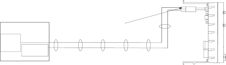
R20 1X UBS Macro B T S Hardw are Installation T ask 14: Connecting +27 V DC P ower
Power cabling and tie down requirements
T o control the inductance at the BTS DC power input due to the spacing between wires used
in the +27 V DC P ower Input Cable (DC), the feed (+V) and return ( -V) wires must be bound
together at intervals of 1 meter or less. Refer to Figure 2 -20 .
Figure 2 -20 +27 V DC power input cable (DC) wire tie -wr ap example
ti-cdma-05693.eps
TIE ALL CABLES AT 1 METER INTERVALS
+27 V Power Source
BREAKER 1
+27 V DC
PDU (Top View)
FRONT
REAR
+27 V DC
- 0 V DC
+27 V DC Power Input
Connector (ORANGE)
- 0 V DC
Contact/lug, DC connector housing and PDU input power
Figure 2 -21 shows the lugs and DC connector housing. This figure also shows the location at
which the +27 V DC Input P ower Cable (DC) connects to the rear of the PDU .
68P09283A62 -3 2 -57
PRELIMINARY A UG 2007
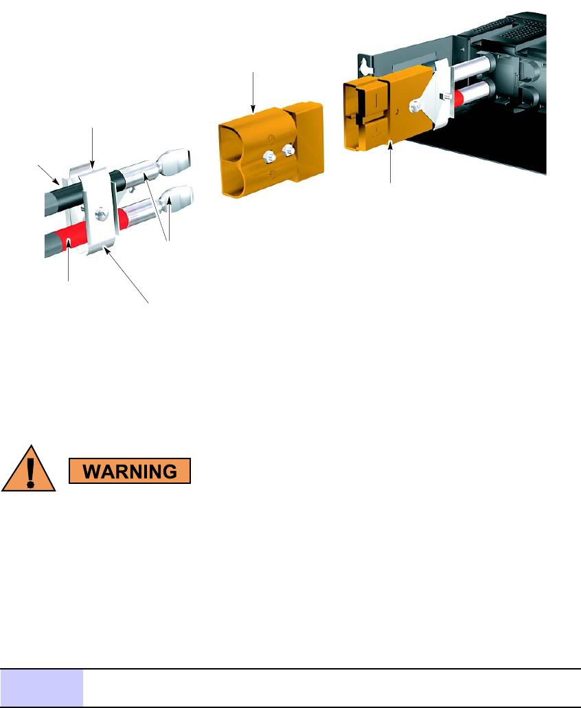
T ask 14: Connecting +27 V DC P ower Chapter 2: UBS Macro B T S Installation Procedure
Figure 2 -21 +27 V DC power input cable (DC) connector and connection to PDU
ti-cdma-05694.eps
PDU
(rear view, shown
partially cut away)
Connector
Housing
(Orange)
(+)
(-)
(-)
Crimp-on
Contact/Lugs
+27 VDC Power
Input (Orange)
RED Wire
(Typical)
(+)
2-Wire +27 VDC
Power Cable
(Customer Supplied)
BLACK WIRE
(Typical)
Cable Clamp
Procedure
P erform the T ask 14 as given in Procedure 2 -8 .
•Do not wear a wrist str ap when servicing the power supplies or power distribution
cabling.
•Ensure that the source for the DC power is in the OFF position.
•Ensure that all of the PDU circuit break ers are OFF .
Procedure 2 -8 Procedure for T ask 14
1
Ensure that the BTS ground cable (DD) is connected between the rack and
the Master Ground Bar (refer to T ask 3).
Continued
2 -58 68P09283A62 -3
PRELIMINARY A UG 2007

R20 1X UBS Macro B T S Hardw are Installation T ask 14: Connecting +27 V DC P ower
Procedure 2 -8 Procedure for T ask 14 (Continued)
2
Ensure that the +27 V DC P ower Input Cable (DC) is NOT connected to the
main +27 V DC power source. Turn OFF the main +27 V DC power source.
3
Remove the components from the DC connector package.
4
Strip 35 mm of insulation from the negative (- V) and positive (+V) wires of
the power cable.
5
Place a DC contact/lug on the negative (- V) and positive (+V) wires of the
power cable. Refer to Figure 2-21 .
6
Using the appropriate crimping tool, crimp the DC contact/lug on to the
wires.
7
Observe the negative (- V) and positive (+V) wire polarities and insert the
DC contacts/lugs into the DC connector housing until an audible click is
heard. Refer to Figure 2-21 .
8
V erify the positive (+V) wire is installed in the positive position and the
negative (- V) wire is installed in the negative (-) position on the connector
housing.
9
Ensure that the wires are firmly fastened to the DC connector housing.
10
Tie the positive (+V) and negative (- V) wires of the cable together as shown
in Figure 2-20 .
1 1
Route the loose end of the +27 V DC P ower Input Cable (DC) to the site +27
V DC source and connect the wires to the source.
12
V erify that proper polarity is maintained from the +27 V DC power source to
the UBS Macro BTS .
13
Use a Digital Multi-Meter (DMM) to measure the voltage
of the DC connector housing that was installed in step 7 .
P erform the following:
•Set the DMM to measure 27 V DC .
•Connect the DMM negative (GND/common) lead to the (-) terminal of
the cable connector .
•Connect the DMM positive lead to the (+) terminal of the cable
connector .
14
Turn on the main +27 V DC power source.
15
Observe the DMM and verify that the voltage is nominally +27 V (range =
+26 to +28 V).
16
Turn off the main +27 V DC power source.
17
Disconnect the DMM from the cable connector .
18
Connect +27 V DC P ower Input Cable (DC) connector to the +27 V DC
input power cable on the rear of the PDU ; Orange connectors mate. Refer
to Figure 2-21 .
68P09283A62 -3 2 -59
PRELIMINARY A UG 2007

T ask 15: Connecting -48 V DC P ower Chapter 2: UBS Macro B T S Installation Procedure
Task 15: Connecting -48 V DC Power■■■■■■■■■■■■■■■■■■■■■■■■■■■■■■■■■■■■■■■■■■■■■■■■■■■■■■■■■■■■■■
■
■
Objectives
T ask 15 is performed for -48 V DC UBS Macro BTS only .
The objectives of this procedure are as follows:
•A ttaching the contact/lugs and connector on the -48 V DC power input cable wires.
•Connecting the -48 V DC input power cable to the rear of the -48 V DC PSM shelf .
•Routing the loose ends of the wires to the site -48 V DC source for connection to the source.
V erify that the +27 V DC output power cable from the PSM shelf is already
connected to the PDU +27 V DC input power cable. This was performed during
T asks 4 -7.
Frame power cables and connector information
The wire gauge (that is, diameter) depends on the required length of the DC power cable (CC).
Refer to T able 2 -8 for the correct wire size.
The DC connector contact/lug size depends on the wire gauge used for the DC power cable (CC).
Refer to T able 2 -15 for DC connector contact/lug part information.
In order to minimize current imbalance between the feed ( -V) and return (+V) wires used in
the cable:
•Ensure that the wire size, length and gauge, of each wire used in the cable are the same.
•Ensure that contacts/lugs used in the connector are identical and match the gauge of
the wire.
Motorola recommends using 2/0 A WG cables for short cable runs; less than 661.11
cm (21.69 ft).
2 -60 68P09283A62 -3
PRELIMINARY A UG 2007

R20 1X UBS Macro B T S Hardw are Installation T ask 15: Connecting -48 V DC P ower
Table 2 -15 –48 V DC connector (Blue) parts information
Item Description Part Number
Qty
Blue DC connector housing Anderson P ower Products Mfr
P art# 912, or Allied Electronics
Stk# 803-0492
1 per –48 V DC power feed
A WG 2/0 connector contact/lug Anderson P ower Products Mfr
P art# 907, or Allied Electronics
Stk# 803-0500
2 per DC connector housing
A WG 3/0 connector contact/lug Anderson P ower Products Mfr
P art# 916, or Allied Electronics
Stk# 803-0502
2 per DC connector housing
A WG 4/0 connector contact/lug Anderson P ower Products Mfr
P art# 908, or Allied Electronics
Stk# 803-0504
2 per DC connector housing
Cable clamp for two single
conductors with hardware
Anderson P ower Products Mfr
P art# 996G1
1 per –48 V DC power feed
Required items
The following items are required:
•One -48 V DC P ower Input Cable (CC) - customer supplied. The wire size, length and
gauge, used for cable (CC) depends on site characteristics (see T able 2 -8 ).
Motorola recommends the use of blue wire for feed ( -V) and black wire for
return (+V).
•T wo Contacts/Lugs – customer supplied. Contact/lug fastens to wire end and is inserted
into DC connector housing. F or contact/lug part number (refer to T able 2 -15 ). Contact/lug
size must match the gage of the wire being used.
•One DC Connector Housing – supplied with UBS BTS . Use Anderson SB350 connector
housing (blue color) or equivalent.
•Crimper tool - Anderson P ower Products part number 1368 - Hydraulic hand tool,
maximum cable size of 300 MCM
•W ire stripper/cutters.
•Digital Multi -Meter (DMM) Fluke Model 8062A with Y8134 test lead kit or equivalent; used
for precision DC and AC measurements, requiring 4 -1/2 digits.
68P09283A62 -3 2 -61
PRELIMINARY A UG 2007
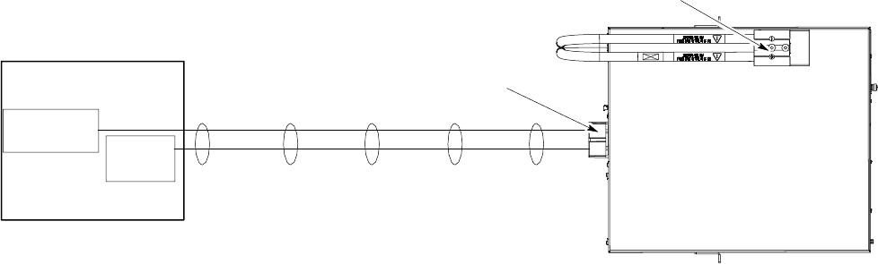
T ask 15: Connecting -48 V DC P ower Chapter 2: UBS Macro B T S Installation Procedure
Power cabling and tie down requirements
T o control the inductance at the BTS DC power input due to the spacing between wires used
in the -48 V DC P ower Input Cable (CC), the feed ( -V) and return (+V) wires must be bound
together at intervals of 1 meter or less. Refer to Figure 2 -22 .
Figure 2 -22 48 V DC power input cable (CC) wire tie -wr ap example
ti-cdma-05695.eps
TIE ALL CABLES AT 1 METER INTERVALS
-48 V Power Source
BREAKER 1
-48 V DC -48 V DC PSM SHELF
(Top View)
-48 V DC Power Input
Connector (BLUE)
+27 V DC Power Output Connector (ORANGE)
+0 V DC
+0 V DC
REAR
FRONT
-48 V DC
Contact/lug, DC connector housing and PDU input power
Figure 2 -23 shows the lugs and DC connector housing. This figure also shows the location at
which the -48 V DC Input P ower Cable (CC) connects to the rear of the PDU .
2 -62 68P09283A62 -3
PRELIMINARY A UG 2007
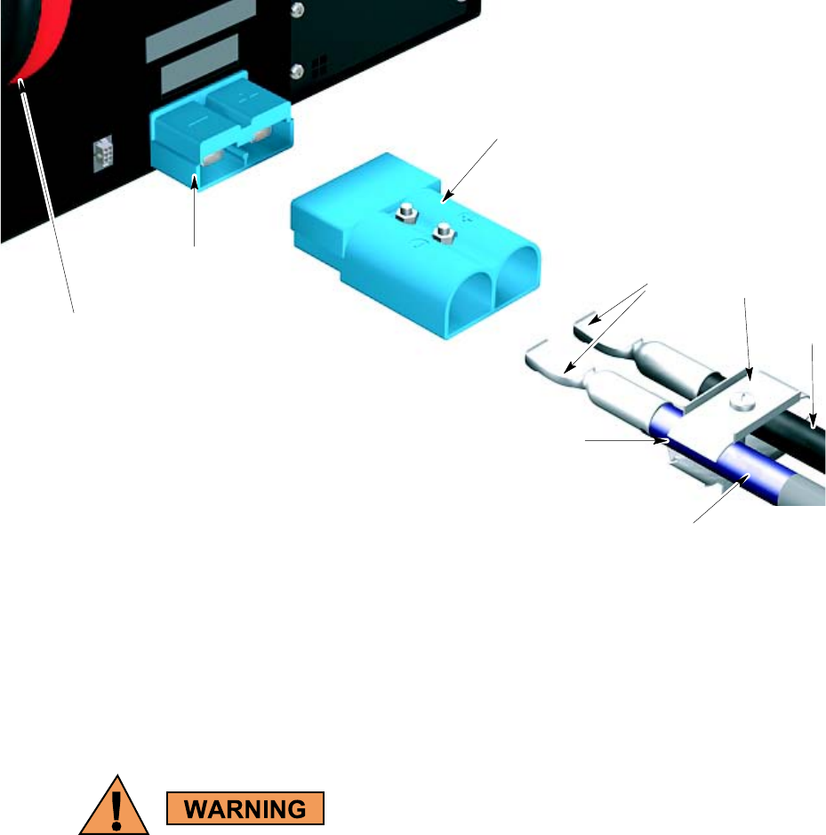
R20 1X UBS Macro B T S Hardw are Installation T ask 15: Connecting -48 V DC P ower
Figure 2 -23 48 V DC power input cable (CC) connector and connection to PSM shelf
ti-cdma-05696.eps
-48 VDC PSM SHELF
(rear view, shown partially cut away)
Connector
Housing (Blue)
(+)
(-)
(-)
???
Crimp-on
Contact/Lugs
-48 VDC Power
Input (Blue)
(+)
2-Wire -48 VDC
Power Cable
(Customer Supplied)
BLACK Wire
(Typical)
BLUE Wire
(Typical)
+27 VDC Power
Output Cable (To PDU)
Cable Clamp
Procedure
P erforming T ask 15 as given in Procedure 2 -9 .
•Do not wear a wrist str ap when servicing the power supplies or power distribution
cabling.
•Ensure that the source for the DC power is in the OFF position.
•Ensure that all of the PDU circuit break ers are OFF .
68P09283A62 -3 2 -63
PRELIMINARY A UG 2007

T ask 15: Connecting -48 V DC P ower Chapter 2: UBS Macro B T S Installation Procedure
Procedure 2 -9 Procedure for T ask 15
1
Ensure that the BTS ground cable (DD) is connected between the rack and
the Master Ground Bar (refer to T ask 3).
2
Ensure that the -48 V DC P ower Input Cable (CC) is NOT connected to the
main -48 V DC power source. Turn OFF the main -48 V DC power source.
3
Remove the components from the DC connector package.
4
Strip 35 mm of insulation from the negative (- V) and positive (+V) wires of
the power cable.
5
Place a DC contact/lug on the negative (- V) and positive (+V) wires of the
power cable. Refer to Figure 2-23 .
6
Using the appropriate crimping tool, crimp the DC contact/lug on to the
wires.
7
Observe the negative (- V) and positive (+V) wire polarities and insert the
DC contacts/lugs into the DC connector housing until a click sound is heard.
Refer to Figure 2-23 .
8
V erify the positive (+V) wire is installed in the positive position and the
negative (- V) wire is installed in the negative (-) position on the connector
housing.
9
Ensure that the wires are firmly fastened to the DC connector housing.
10
Tie the positive (+V) and negative (- V) wires of the cable together as shown
in Figure 2-22 .
1 1
Route the loose end of the -48 V DC P ower Input Cable (CC) to the site -48 V
DC source and connect the wires to the source.
12
V erify that proper polarity is maintained from the -48 V DC power source to
the UBS Macro BTS .
13
Use a Digital Multi-Meter (DMM) to measure the voltage
of the DC connector housing that was installed in step 7 .
P erform the following:
•Set the DMM to measure 48 V DC .
•Connect the DMM negative (GND/common) lead to the (-) terminal of
the cable connector .
•Connect the DMM positive lead to the (+) terminal of the cable
connector .
14
Turn on the main –48 V DC power source.
15
Observe the DMM and verify that the voltage is nominally +48 V (range =
+40 to +60 V).
16
Turn off the main –48 V DC power source.
17
Disconnect the DMM from the cable connector .
18
Connect -48 V DC P ower Input Cable (CC) connector to the -48 V DC input
power connector on the rear of the PSM shelf; blue connectors mate. Refer
to Figure 2-23 .
2 -64 68P09283A62 -3
PRELIMINARY A UG 2007

R20 1X UBS Macro B T S Hardw are Installation T ask 16: Connecting 220 V AC P ower
Task 16: Connecting 220 V AC Power■■■■■■■■■■■■■■■■■■■■■■■■■■■■■■■■■■■■■■■■■■■■■■■■■■■■■■■■■■■■■■
■
■
Objectives
T ask 16 is performed for 220 V AC UBS Macro BTS only .
The objectives of this procedure are as follows:
•A ttaching customer supplied wiring and conduit for 220 V AC lines.
•Connecting wires and required insertion bridges to the AC INP UT terminal block on the
rear of the AC PSM shelf .
•Routing the loose ends of the wires to the site 220 V AC source for connection to the source.
V erify that the +27 V DC output power cable from the PSM shelf is already
connected to the PDU +27 V DC input power cable. This was performed during
T asks 4 -7.
Frame AC power cables and wiring information
The AC PSM shelf and AC PSMs can operate with the following AC power inputs:
•Input AC V oltage R ange: 154 V AC to 300 V AC
•Single -Phase
•3 -Phase ST AR
•3 -Phase DEL T A
Consider the following AC power input circuit characteristics:
•The AC PSM shelf terminal block has seven terminals; one for Ground plus six for AC
line wires and insertion bridges.
•The AC PSM shelf terminal block Ground terminal can accommodate a wire size range of
2 A WG to 10 A WG .
•The AC PSM shelf terminal block AC line terminals can accommodate a wire size range of
2 A WG to 10 A WG .
68P09283A62 -3 2 -65
PRELIMINARY A UG 2007
T ask 16: Connecting 220 V AC P ower Chapter 2: UBS Macro B T S Installation Procedure
•Input AC cable sizing should be determined by Local Electrical Codes, using 90 C minimum
rated conductors, and de–rating for 50 C operation.
•The customer must provide a disconnect device and an over current protection device for
the AC circuit supplying the UBS Macro BTS . A circuit breaker size of 30 Amperes is
recommended, or as appropriate set by Local Electrical Code.
Required items
The following items are required:
•Conduit - customer supplied
•W ire for Ground and AC lines - customer supplied
•Insertion bridges – supplied with AC PSM shelf; two 3 -position bridges and three 2 -position
bridges
•T20 TORX bit with 12 -inch extension
•Flat blade screwdriver
•W ire stripper/cutters
AC PSM shelf AC power input detail
Figure 2 -24 shows the location of the AC PSM shelf AC power input terminals and wiring
details for:
•Single -Phase
•3 -Phase ST AR
•3 -Phase DEL T A
2 -66 68P09283A62 -3
PRELIMINARY A UG 2007
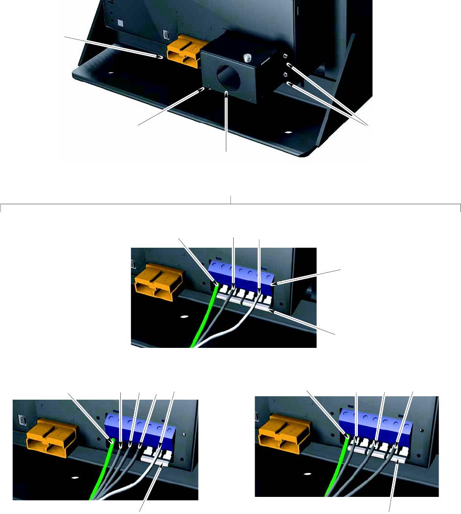
R20 1X UBS Macro B T S Hardw are Installation T ask 16: Connecting 220 V AC P ower
Figure 2 -24 AC PSM shelf AC power input terminal block and wiring details
ti-cdma-05697.eps
AC PSM Shelf
(rack mounted, rear view, shown partially cut away)
+27 VDC Power
Output Connector
for Battery Backup
AC Input Terminal Block Protective
Cover Box
(See Detail A for Wiring Configurations)
Conduit/Wire
Entry Hole
2 Screws On Each Side
Secure Protective Cover
Box To PSM Shelf
Detail A - AC Input Terminal Wiring Configurations (protective cover box removed)
Single-Phase
Ground
GroundGround
AC Input Terminal Block
(terminal screw access
holes on top)
Two 3-position
Insertion Bridges
One 3-position
Insertion Bridge
Three 2-position
Insertion Bridges
3-Phase STAR3-Phase DELTA
L3 L2 L1 NL3 L1 L2
L1 N
68P09283A62 -3 2 -67
PRELIMINARY A UG 2007

T ask 16: Connecting 220 V AC P ower Chapter 2: UBS Macro B T S Installation Procedure
Procedure
P erform T ask 16 as given in Procedure 2 -10 .
•Do not wear a wrist str ap while servicing the power supplies or power distribution
cabling.
•Ensure that the source for the AC power is in the OFF position.
•Ensure that all of the PDU circuit break ers are OFF .
Procedure 2 -10 Procedure for T ask 16
1
Set the source for the AC voltage to the OFF position.
2
Ensure that the BTS ground cable (DD) is connected between the rack and
the Master Ground Bar (refer to T ask 3).
3
On the rear of the PSM shelf , locate the AC input terminal block cover box.
Using a TORX T20 bit and driver , remove the 4 screws securing the cover
box to the PSM shelf (refer to Figure 2-24 ).
4
Remove the cover box from the PSM shelf to expose the AC input terminal
block.
5
A ttach conduit to the cover box.
6
Route the AC wires and the earth ground wire through the conduit and the
cover box. Leave wires extending to reach the AC input terminal block.
7
Strip 25 mm of insulation from each of the AC supply line wires and the
earth ground wire.
8
Locate the ground terminal on the AC input terminal block (refer to
Figure 2-23 ).
9
Using a flat blade screwdriver , turn the ground terminal screw counter
clockwise (CCW) until the terminal is fully open. Insert the earth ground
wire into the ground terminal. Turn the ground terminal screw clockwise
(CW) to close the terminal and secure the wire. Tighten the terminal screw
to 4.0 - 4.5 N-m (35 - 40 in-lb).
10
Determine if the AC input terminal block already has insertion bridges
properly installed for the desired AC supply configuration:
•Single-Phase
•3-Phase ST AR
•3-Phase DEL T A
Refer to Figure 2-24 as needed.
Continued
2 -68 68P09283A62 -3
PRELIMINARY A UG 2007
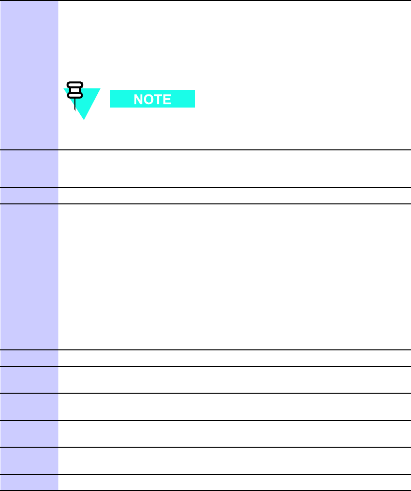
R20 1X UBS Macro B T S Hardw are Installation T ask 16: Connecting 220 V AC P ower
Procedure 2 -10 Procedure for T ask 16 (Continued)
1 1
Open the six line terminals as follows:
•Insert a flat blade screwdriver into each screw hole on top of the
terminal block.
•Turn the terminal screw CCW until the terminal is fully open..
F ailure to fully open the terminals can cause improper placement
of the insertion bridges in later steps.
12
Place an insertion bridge into the proper terminals. While holding the
bridge with one hand, turn the corresponding terminal screws CW until the
bridge is securely clamped.
13
Repeat step 12 for any remaining terminals requiring an insertion bridge.
14
Connect the AC supply line wires to the proper terminals as follows:
•Insert a flat blade screwdriver into the appropriate screw hole on top
of the terminal block.
•Turn the terminal screw CCW until the terminal is fully open.
•Insert the appropriate wire into the terminal.
•While holding the wire with one hand, turn the corresponding terminal
screw CW until the wire is securely clamped. Tighten the terminal
screw to 4.0 - 4.5 N-m (35 - 40 in-lb).
Refer to Figure 2-24 as needed.
15
Repeat step 14 for any unconnected AC supply line wires.
16
V isually inspect all insertion bridge(s) and wires for proper placement. All
conductors must be inside the clamp of each terminal block.
17
Place the cover box, with conduit attached, in position over the AC input
terminal block.
18
Insert the 4 screws to secure the cover box to the PSM shelf . Ensure that
the wires are not pinched.
19
Using a TORX T20 bit and driver , tighten the 4 screws to 1.6 - 1.8 N-m (14 -
16 in-lb).
20
Complete the installation of the AC wiring at the AC P ower source.
68P09283A62 -3 2 -69
A UG 2007 PRELIMINARY
T ask 16: Connecting 220 V AC P ower Chapter 2: UBS Macro B T S Installation Procedure
2 -70 68P09283A62 -3
PRELIMINARY A UG 2007

C h a p t e r
3
Low -to -Mid Capacity Frame Expansion
Procedures
■■■■■■■■■■■■■■■■■■■■■■■■■■■■■■■■■■■■■■■■■■■■■■■■■■■■■■■■■■■■■■
■
■
■
■
68P09283A62 -3 3 -1
A UG 2007 PRELIMINARY

Low -to -Mid Capacit y Fr ame Expansion Ov erview Chapter 3: Low -to -Mid Capacit y Fr ame Expansion Procedures
Low -to -Mid Capacity Frame Expansion Overview■■■■■■■■■■■■■■■■■■■■■■■■■■■■■■■■■■■■■■■■■■■■■■■■■■■■■■■■■■■■■■
■
■
The R20 UBS Macro BTS supports single band 800 MHz or 1.9 GHz RF band, up to
two XMIs, up to two DMIs and one S SI. UBS Macro BTS Frame configurations with
up to four XMIs and up to five DMIs will be available in the future.
This chapter provides information and procedures needed for expanding the low -capacity UBS
Macro BTS starter/expansion frame to the mid -capacity frame configuration.
The mid -capacity frame consists of the low -capacity frame equipment plus the following
additional expansion equipment:
•second XMI, required.
•second DMI, required.
•circuit breaker/output power connector assemblies; one required for each of the following:
second XMI and second DMI.
•second set of IDRFs, required.
•optional RX splitter or RX share cable.
•third PSM, required for –48 V or 220 V AC only . Three PSMs are required for the mid
capacity configuration. The third PSM is for redundancy .
Cabling of the RX splitter to the XMIs will be performed after all of the additional expansion
equipment (i.e., XMI, DMI, S SI, circuit breaker/output power connector assemblies, etc.) is
installed in the frame.
How to use this chapter
Typically the installer is directed to this chapter via T ask 6: Expanding the Low -capacity Frame
on page 2 - 42 of Chapter 2 UBS Macro BTS Installation Procedure .
P erform all of the applicable procedures, in this chapter , for expanding the low -capacity UBS
Macro BTS starter/expansion frame to the mid -capacity frame configuration.
A fter all of the additional expansion equipment is installed, go to T ask 7: Cabling the Optional
PSM Shelf on page 2 - 43 of Chapter 2 UBS Macro BTS Installation Procedure , and continue
performing the remaining tasks in sequential order .
3 -2 68P09283A62 -3
PRELIMINARY A UG 2007

R20 1X UBS Macro B T S Hardw are Installation Adding Circuit Break ers/Connectors to PDU
Adding Circuit Breakers/Connectors to PDU■■■■■■■■■■■■■■■■■■■■■■■■■■■■■■■■■■■■■■■■■■■■■■■■■■■■■■■■■■■■■■
■
■
Objective
The objective of this section is to install additional circuit breaker/output power connector
assemblies in the PDU . These additional circuit breaker/output power connector assemblies are
required to allow the PDU to provide DC power to the expansion equipment being added to
the UBS Macro BTS frame.
The circuit breaker/output power connector assemblies are located on the PDU front panel.
Each circuit breaker/output power connector assembly is arranged so that the circuit breaker
is just below the corresponding DC output power connector .
The PDU can be equipped with the following circuit breaker/output power connector assemblies:
•up to four 90A for XMI 1 – XMI 4
•up to five 20A for DMI 1 – DMI 5
•up to two 20A for S SI 1 – S SI 2
•up to two 10A for accessory groups ACC 1 – ACC 2
The PDU in the UBS Macro BTS low -capacity starter/expansion frame is already equipped with
the following circuit breaker/output power connector assemblies:
•one 90A for XMI 1
•two 20A for DMI 1 – DMI 2
•one 20A for S SI 1
•zero 10A for no accessories
The type and quantity of circuit breaker/output power connector assemblies required depends
on which circuit breaker/output power connector assemblies are not already equipped in the
PDU , but are needed to support the additional expansion equipment.
Required items
The following items are required:
•Appropriate type and quantity of circuit breaker/output power connector assemblies to
be added for expansion purposes
90A circuit breaker/output power connector assembly (Motorola model STLN4093)
20A circuit breaker/output power connector assembly (Motorola model STLN6472)
68P09283A62 -3 3 -3
PRELIMINARY A UG 2007
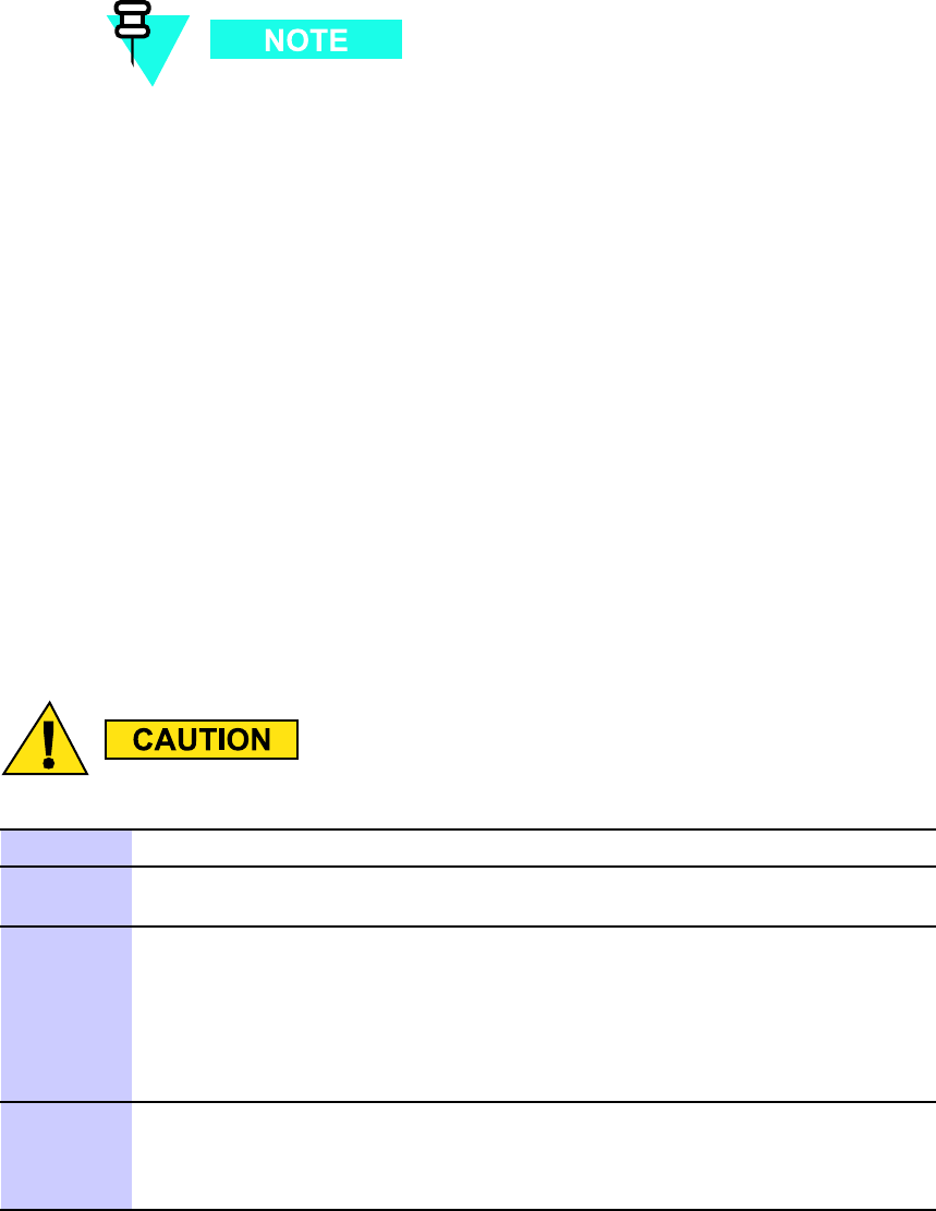
Adding Circuit Break ers/Connectors to PDU Chapter 3: Low -to -Mid Capacit y Fr ame Expansion Procedures
Mounting screws are provided with each circuit breaker/output power
connector assembly; four screws with the 90A assembly and two screws
with the 20A assembly .
•Side cutters; diagonal pliers or wire cutter
•Small knife
•TORX T25 bit and driver
•T orque driver
Procedure
Procedure 3 -1 contains the steps for adding a circuit breaker/output power connector assembly
to the PDU .
Procedure 3 -1 Adding a Circuit Break er/Output P ower Connector Assembly to the
PDU
Mak e sure DC input power is not applied to the PDU before performing Procedure 3 -1 .
1
Set all PDU front panel circuit breakers to the off (pulled out) position.
2
Disconnect all DC power cables from the PDU front panel. Dress these cables
away from the PDU front panel.
3
Remove the PDU front panel as follows:
•See Figure 3-1 Adding a Breaker Assembly Module to the PDU on page
3- 6 photograph A.
•While depressing the retaining tab on the left and right front ends of the
PDU , slide the PDU front panel forward and off of the PDU .
4
Install the additional circuit breaker/output power connector assemblies in
the required locations on the PDU front panel DC output power bus (see
Figure 3-1 Adding a Breaker Assembly Module to the PDU on page 3- 6
photograph B.
Continued
3 -4 68P09283A62 -3
PRELIMINARY A UG 2007
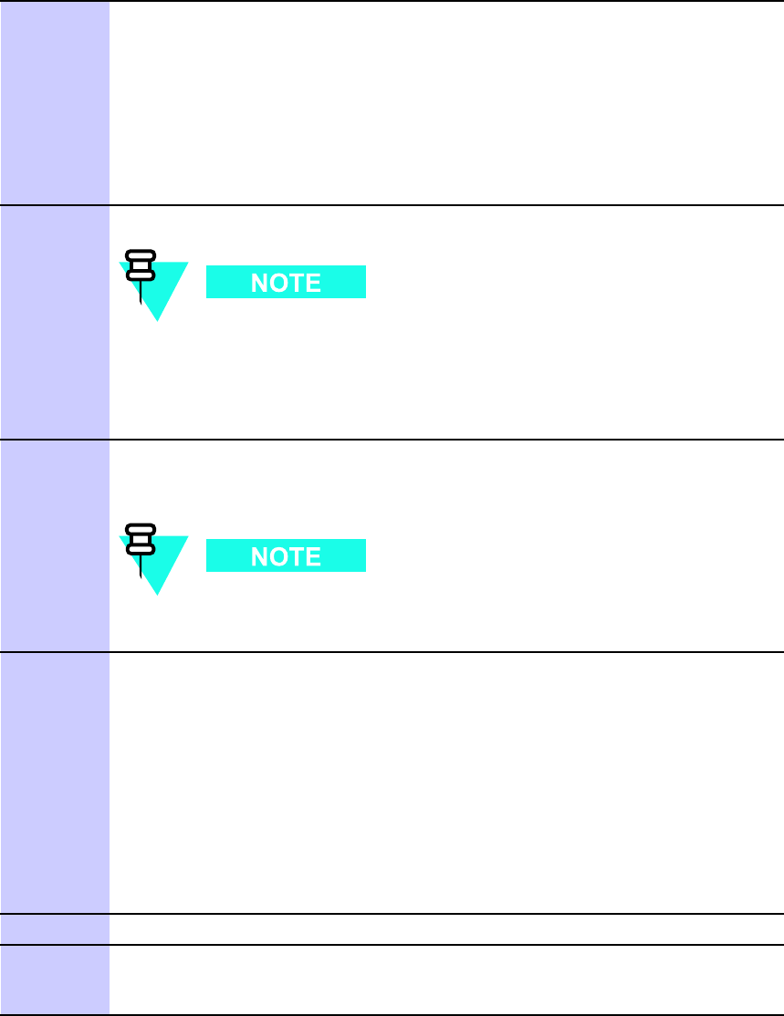
R20 1X UBS Macro B T S Hardw are Installation Adding Circuit Break ers/Connectors to PDU
Procedure 3 -1 Adding a Circuit Break er/Output P ower Connector Assembly to the
PDU (Continued)
5
P osition the circuit breaker/output power connector assembly as follows:
•Circuit breaker actuator at the bottom and the DC output power
connector at the top
•Circuit breaker actuator facing toward the front of the frame
•Align mounting screw holes of the circuit breaker/output power
connector assembly with the corresponding screw holes on the PDU
front panel DC output power bus.
6
Insert the supplied mounting screws into the screw holes.
T wo screws on top and bottom for the 90A assembly . One screw on
top and bottom for the 20A assembly .
Using a TORX T25 driver , tighten the mounting screws to 4.8 N-m (42.25
in-lb) ±10%.
7
Using side cutters, cut out the applicable circuit breaker actuator and the
corresponding connector covers on the PDU front panel (see Figure 3-1
Adding a Breaker Assembly Module to the PDU on page 3- 6 photograph C.
It may be necessary to use a small knife to remove any of the tabs
that do not cut cleanly .
8
Reattach the PDU front panel to the PDU as follows:
•See Figure 3-1 Adding a Breaker Assembly Module to the PDU on page
3- 6 photograph D.
•Align the PDU front panel with the PDU circuit breaker actuators and
power connectors while inserting the PDU front panel retaining tabs into
the retainer on the left and right front ends of the PDU .
•Slide the PDU front panel onto the front of the PDU .
•Firmly press on the ends of the PDU front panel until each end tab snaps
into place.
9
Set all PDU front panel circuit breakers to the off (pulled out) position.
10
Reconnect all DC power cables that were disconnected in step 2 of this
procedure. Make sure that each cable is connected to the proper PDU front
panel power connector .
68P09283A62 -3 3 -5
PRELIMINARY A UG 2007
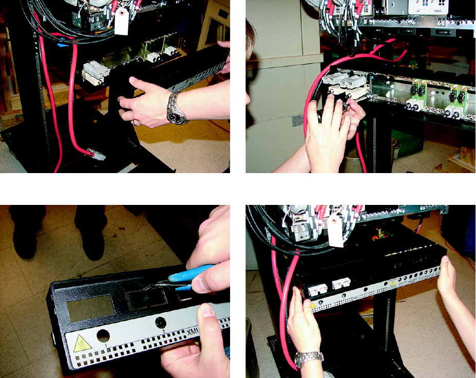
Adding Circuit Break ers/Connectors to PDU Chapter 3: Low -to -Mid Capacit y Fr ame Expansion Procedures
Procedural reference diagram
The following diagram helps clarify certain steps in Procedure 3 -1 .
Figure 3 -1 Adding a Break er Assembly Module to the PDU
ti-cdma-06031.eps
A B
C D
3 -6 68P09283A62 -3
PRELIMINARY A UG 2007

R20 1X UBS Macro B T S Hardw are Installation Adding an XMI
Adding an XMI■■■■■■■■■■■■■■■■■■■■■■■■■■■■■■■■■■■■■■■■■■■■■■■■■■■■■■■■■■■■■■
■
■
Objective
The objective of this section is to mount an additional XMI into the XMI shelf .
Cabling of the additional XMI will be performed after all of the additional expansion
equipment (i.e., IDRFs, DMI, circuit breaker/output power connector assemblies, etc.)
that connects to the additional XMI is installed in the frame.
Required items
Parts
The following applicable additional XMI is required:
•800 MHz XMI assembly with removable XMI handle attached (Motorola model SGTF4194).
•1.9 GHz XMI assembly with removable XMI handle attached (Motorola model STWG4000).
Manpower
The XMI module is hea vy . T wo people are required to lift, carry , or handle the XMI
module.
The XMI weighs 23 -28 kg (50.7 -61.7 lb) depending on the RF band.
68P09283A62 -3 3 -7
PRELIMINARY A UG 2007
Adding an XMI Chapter 3: Low -to -Mid Capacit y Fr ame Expansion Procedures
Tools
The following tools are required:
•TORX T25 bit and driver
•T orque driver
Procedure
Procedure 3 -2 contains the steps for adding a 2nd XMI to the XMI shelf .
Procedure 3 -2 Adding a 2nd XMI to the XMI Shelf
The XMI module is hea vy . T wo people are required to lift, carry , or
handle the XMI module.
•Be sure the remo v able XMI handle is attached to the front of
the XMI before ph ysically handling the module.
•Be sure two people use both hands and wear protectiv e
footwear when handling the XMI.
•Be sure to use two people to support the module while sliding
the module out of or into the shelf slot.
An XMI module that is not in a shelf should alw a ys be set on its
side and nev er on its edge. This will prev ent the XMI module from
tipping o v er and causing damage or injury .
1
Remove the XMI from its packaging and inspect it for damage.
2
XMI 2 mounts in the XMI shelf slot just to the right of XMI 1. XMI
3 mounts in the XMI shelf slot just to the right of XMI 2. XMI 4
mounts in the XMI shelf slot just to the right of XMI 3.
This step requires two people. P erform the following:
Continued
3 -8 68P09283A62 -3
PRELIMINARY A UG 2007

R20 1X UBS Macro B T S Hardw are Installation Adding an XMI
Procedure 3 -2 Adding a 2nd XMI to the XMI Shelf (Continued)
•One person grasp the XMI by the handle with both hands. The second
person grasp the XMI fan tray sides with both hands. Using safe lifting
technique (i.e. lift with your legs not your back), pick up the XMI and
carry it over to the front of the frame.
•While one person holds the XMI by the handle with both hands, the
second person supports the bottom of the module with one hand and the
top of the module with the other hand. Lift the XMI into the appropriate
XMI shelf slot rails and gently slide it all of the way into the shelf slot.
3
Insert the four XMI mounting screws; two screws at each of the top and
bottom mounting tabs on the front of the module. Using a T25 TORX driver ,
tighten the screws to 4.8 N-m (42.25 in-lb) ±10%.
Procedural reference diagram
The following diagram helps clarify certain steps in Procedure 3 -2 .
68P09283A62 -3 3 -9
PRELIMINARY A UG 2007
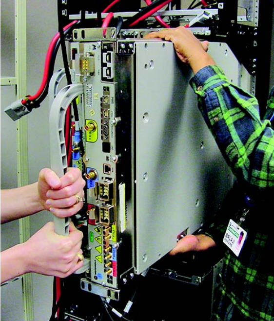
Adding an XMI Chapter 3: Low -to -Mid Capacit y Fr ame Expansion Procedures
Figure 3 -2 Installing a 2nd XMI
ti-cdma-06375.eps
3 -10 68P09283A62 -3
PRELIMINARY A UG 2007

R20 1X UBS Macro B T S Hardw are Installation Adding a DMI
Adding a DMI■■■■■■■■■■■■■■■■■■■■■■■■■■■■■■■■■■■■■■■■■■■■■■■■■■■■■■■■■■■■■■
■
■
Objective
The objective of this section is to mount an additional DMI into the XMI shelf .
Cabling of the additional DMI will be performed after all of the additional expansion
equipment (i.e., XMI, circuit breaker/output power connector assemblies, etc.) that
connects to the additional DMI is installed in the frame.
Required items
Parts
The additional DMI is application dependent. Use one of the following factory built DMI
assemblies as applicable:
All models of DMI assemblies include: DMI chassis with controller board, fans and
front panel.
•DMI assembly with one 1X CDMA modem board (Motorola model STLN6681).
•DMI assembly with one EV -DO modem board (Motorola model STLN6682).
•DMI assembly with two 1X CDMA modem boards (Motorola model STLN6683).
•DMI assembly with one 1X CDMA modem board and one EV -DO modem board (Motorola
model STLN6684).
•DMI assembly with two EV -DO modem boards (Motorola model STLN6679).
68P09283A62 -3 3 -11
PRELIMINARY A UG 2007
Adding a DMI Chapter 3: Low -to -Mid Capacit y Fr ame Expansion Procedures
Tools
The following tools are required:
•TORX T25 bit and driver
•T orque driver
•ESD wrist strap
Prerequisite
ESD handling precautions must be adhered to when handling the DMI assembly . W ear
a conductiv e, high impedance wrist str ap during handling.
The procedures in this chapter requires working on or around circuitry that is extremely
sensitive to ESD .
Procedure
Procedure 3 -3 contains the steps for adding a 2nd DMI to the XMI shelf .
Procedure 3 -3 Adding a 2nd DMI to the XMI Shelf
1
Set the additional DMI assembly , in its packaging, near the UBS Macro BTS
frame.
2
ESD handling precautions must be adhered to during this
procedure. W ear a conductiv e, high impedance wrist str ap .
Plug the end of the ESD wrist strap into the UBS Macro BTS frame ESD jack
This jack is located in the middle of the upper XMI shelf bracket. A ttach
the wrist strap to your wrist.
3
Remove the additional DMI from its packaging and inspect it for damage.
4
Install the DMI assembly into the appropriate empty DMI housing in the UBS
Macro BTS frame by performing the following:
1. P osition the DMI assembly on its bottom edge so that the front panel
handle is on the right and the retaining fastener is at the top.
Continued
3 -12 68P09283A62 -3
PRELIMINARY A UG 2007

R20 1X UBS Macro B T S Hardw are Installation Adding a DMI
Procedure 3 -3 Adding a 2nd DMI to the XMI Shelf (Continued)
2. Pick up the DMI assembly with two hands.
3. Insert the rear of the DMI assembly into the empty housing.
4. Slide the DMI assembly completely into the housing (see Figure 3-3
Installing a 2nd DMI on page 3- 14 .
5. Turn the retaining fastener CW (Clockwise) until finger tight to secure
the DMI assembly in the housing.
68P09283A62 -3 3 -13
PRELIMINARY A UG 2007
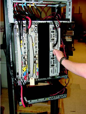

R20 1X UBS Macro B T S Hardw are Installation Adding a Second Set of IDRFs
Adding a Second Set of IDRFs■■■■■■■■■■■■■■■■■■■■■■■■■■■■■■■■■■■■■■■■■■■■■■■■■■■■■■■■■■■■■■
■
■
Objective
The objective of this section is to mount a second set of IDRFs into the IDRF shelf .
Cabling of the second set of IDRFs to the second XMI will be performed after all of
the additional expansion equipment (i.e., XMI, DMI, circuit breaker/output power
connector assemblies, etc.) is installed in the frame.
The second set of IDRFs consists of:
•one IDRF for an omni antenna configuration.
•three IDRFs, one per sector , for a 3 -sector antenna configuration.
The second set of IDRFs mounts in the right -half of the IDRF shelf . The second set of IDRFs are
designated as sector 1, 2 and 3 from left to right.
Required items
Parts
The proper quantity , for omni or 3 -sector antenna configuration, of the following applicable
IDRF is required:
•China Full Band 800 MHz IDRF (Motorola model STFN4009)
•India Full Band 800 MHz IDRF (Motorola model STFN4010)
•US Full Band 800 MHz IDRF (Motorola model STFN4015)
•US A -band 800 MHz IDRF (Motorola model STFN4016)
•US B -band 800 MHz IDRF (Motorola model STFN4017)
•1.9 GHz IDRF (Motorola model STFG4055)
68P09283A62 -3 3 -15
PRELIMINARY A UG 2007

Adding a Second Set of IDRFs Chapter 3: Low -to -Mid Capacit y Fr ame Expansion Procedures
Tools
The following tools are required:
•TORX T25 bit and driver
•T orque driver
Procedure
Procedure 3 -4 contains the steps for adding a second set of IDRFs to the IDRF shelf .
Procedure 3 -4 Adding a second set of IDRFs to the IDRF shelf
1
Remove the additional IDRFs from their packaging and inspect them for
damage.
2
While working at the front/top of the UBS Macro BTS frame, pick up an
additional IDRF and mount it into the IDRF shelf as follows:
•P osition the IDRF with the IDRF mounting plate on top/facing upward
and the mounting plate flange is on the right side (see Figure 3-4
Installing the second set of IDRFs on page 3- 17 photograph B).
•Insert the first IDRF into the sector 1 position on the right half of the top
of the IDRF shelf (see photograph A).
•Slide the IDRF down into the IDRF shelf .
3
Repeat step 2 for the remaining IDRFs, but insert them in sector 2 and sector
3 positions.
4
Insert four mounting screws through each IDRF mounting plate and into the
IDRF shelf . Using a T25 TORX driver , tighten the mounting screws for all of
the additional IDRFs to 4.8 N-m (42.25 in-lb) ±10%.
3 -16 68P09283A62 -3
PRELIMINARY A UG 2007
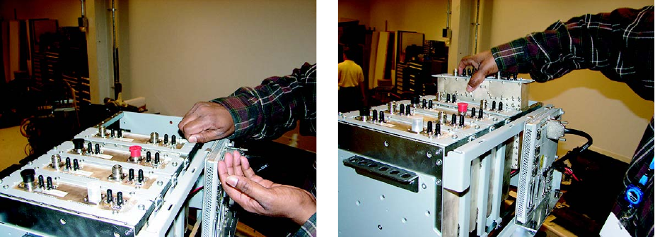

Adding an Optional RX Splitter Chapter 3: Low -to -Mid Capacit y Fr ame Expansion Procedures
Adding an Optional RX Splitter■■■■■■■■■■■■■■■■■■■■■■■■■■■■■■■■■■■■■■■■■■■■■■■■■■■■■■■■■■■■■■
■
■
Objective
The objective of this section is to mount the optional RX splitter onto the bottom of the XMI shelf .
Cabling of the RX splitter to the XMIs will be performed after all of the additional
expansion equipment (i.e., XMI, DMI, circuit breaker/output power connector
assemblies, etc.) is installed in the frame.
Required items
Parts
The following part is required:
•W ide band (800 MHz through 2.1 GHz RF bands) RX splitter (Motorola model STRG4029)
Tools
The following tools are required:
•TORX T25 bit and driver
•T orque driver
Procedure
Procedure 3 -5 contains the steps for adding the RX splitter to the bottom of the XMI shelf .
Procedure 3 -5 Adding an RX splitter to the XMI shelf
1
Remove the RX splitter from its packaging and inspect it for damage.
2
While working at the front of the UBS Macro BTS frame, pick up the RX
splitter and mount it onto the bottom of the XMI shelf as follows:
Continued
3 -18 68P09283A62 -3
PRELIMINARY A UG 2007
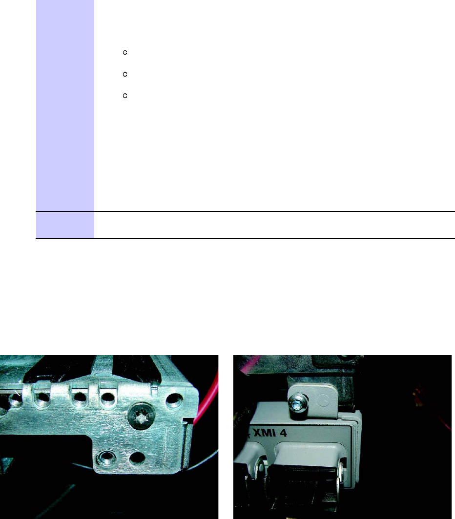
R20 1X UBS Macro B T S Hardw are Installation Adding an Optional RX Splitter
Procedure 3 -5 Adding an RX splitter to the XMI shelf (Continued)
•See Figure 3-5 Mounting the RX splitter on page 3- 19 .
•P osition the RX splitter as follows:
RX splitter I/O connectors facing toward front of the frame.
RX splitter mounting tabs, one on each end of splitter , facing up.
In front of the XMI shelf bottom bracket.
•Align the guide pins on each RX splitter mounting tab with the
corresponding hole located on the XMI shelf bottom bracket (see
photograph A).
•Insert the guide pins into the holes and hold the RX splitter mounting
tabs against the XMI shelf bottom bracket.
•Insert a mounting screw through each RX splitter mounting tab and into
the XMI shelf bottom bracket. (see photograph B).
3
Using a T25 TORX driver , tighten the mounting screws to 4.8 N-m (42.25
in-lb) ±10%.
Procedural reference diagram
The following diagram helps clarify certain steps in Procedure 3 -5 .
Figure 3 -5 Mounting the RX splitter
ti-cdma-06036.eps
A B
68P09283A62 -3 3 -19
PRELIMINARY A UG 2007

Adding a third PSM (–48 V or 220 V AC only) Chapter 3: Low -to -Mid Capacit y Fr ame Expansion Procedures
Adding a third PSM (–48 V or 220 V AC only)■■■■■■■■■■■■■■■■■■■■■■■■■■■■■■■■■■■■■■■■■■■■■■■■■■■■■■■■■■■■■■
■
■
A third PSM is required when expanding a –48 V DC or 220 V AC UBS Macro BTS
frame from low capacity to mid capacity . The third PSM is for redundancy .
Objective
F or –48 V or 220 V AC only , install the appropriate PSM into slot 3 of the PSM shelf . If
applicable, remove the filler plate that covers slot 3 of the PSM shelf and then install the
appropriate PSM into slot 3.
Required items
Parts
Nev er plug a –48 V DC PSM into a 220 V AC PSM shelf .
Nev er plug a 220 V AC PSM into a -–48 V DC PSM shelf .
One of either the following parts is required:
•–48 V DC P ower Supply Module (–48 V DC PSM) — Motorola model STPN4037
•220 V AC P ower Supply Module (220 V AC PSM) — Motorola model STPN4036
Tools
The following tools are required:
•TORX T25 bit and driver
•T orque driver
3 -20 68P09283A62 -3
PRELIMINARY A UG 2007
R20 1X UBS Macro B T S Hardw are Installation Adding a third PSM (–48 V or 220 V AC only)
Procedure
Procedure 3 -6 contains the steps for adding a third PSM to the PSM shelf .
Procedure 3 -6 Adding a 3rd PSM to the PSM shelf
1
Use a T25 TORX bit and driver to completely loosen the captive retaining
thumbscrew on the filler plate that covers slot 3 of the PSM shelf . Remove
the filler plate.
2
PSM weighs appro ximately 5 kg. Be careful when handling the PSM
to prev ent damage to the equipment and personal injury .
Install the appropriate PSM into PSM shelf slot 3 as follows:
1. Grasp the handle on the front panel of the PSM with one hand while
carefully supporting the bottom of the module with the other hand.
2. Properly orient the PSM and insert it into the slot.
3. Slowly slide the module into the shelf until the rear connectors are
fully seated. Make sure that the PSM is fully engaged with the shelf
backplane slot connectors.
3
Using a T25 TORX bit and torque driver , tighten the captive retaining
thumbscrew to 2.37 N-m (21 in-lb).
68P09283A62 -3 3 -21
PRELIMINARY A UG 2007

Mid -capacit y Expansion Interconnect Cabling Chapter 3: Low -to -Mid Capacit y Fr ame Expansion Procedures
Mid -capacity Expansion Interconnect Cabling■■■■■■■■■■■■■■■■■■■■■■■■■■■■■■■■■■■■■■■■■■■■■■■■■■■■■■■■■■■■■■
■
■
Remember – A fter all of the additional expansion equipment is installed and cabled,
you
must
go to T ask 7: Cabling the Optional PSM Shelf on page 2 - 43 of Chapter 2
UBS Macro BTS Installation Procedure , and continue performing the remaining
installation tasks in sequential order .
Objective
The objective of this section is to route and connect all required cabling between the additional
mid -capacity expansion equipment (i.e., 2nd XMI, 2nd DMI, optional RX splitter , circuit
breaker/output power connector assemblies) that is installed in the frame.
The RX splitter is optional equipment for expansion to mid -capacity . An RX share
cable can be used instead of the RX splitter for interconnecting RX RF signals
between XMI 1 and XMI 2.
Installing DC power cables
Locate the required DC power cables and then perform Procedure 3 -7 through Procedure 3 -8
as needed.
Required DC power cables
•XMI DC power cable (Motorola part number 3088319T03)
•DMI DC power cable (Motorola part number 3088961T05)
3 -22 68P09283A62 -3
PRELIMINARY A UG 2007

R20 1X UBS Macro B T S Hardw are Installation Mid -capacit y Expansion Interconnect Cabling
DC power cabling procedures
Procedure 3 -7 Installing the XMI 2 DC power cable
1
Locate the XMI DC power cable (Motorola part number 3088319T03).
2
Connect the appropriate end of the XMI DC power cable to the +27 V DC
input power connector on the top of XMI 2 front panel.
Continued
68P09283A62 -3 3 -23
PRELIMINARY A UG 2007

Mid -capacit y Expansion Interconnect Cabling Chapter 3: Low -to -Mid Capacit y Fr ame Expansion Procedures
Procedure 3 -7 Installing the XMI 2 DC power cable (Continued)
3
Route the loose end of the XMI DC power cable as follows:
1. Through the opening above XMI 2 between the XMI shelf and the IDRF
shelf to the back of the XMI shelf .
2. Down and around the left side of the rear of XMI 2.
T o avoid blocking exhaust air from the XMI, the XMI DC power
cable must not be routed directly behind the XMI.
3. Down to the PDU and over the top of the PDU to the PDU front panel.
4
Connect the loose end of the XMI DC power cable to the XMI 2 DC output
power connector on the PDU front panel.
Procedure 3 -8 Installing the DMI 2 DC power cable
1
Locate the DMI DC power cable (Motorola part number 3088961T05).
2
Connect the appropriate end of the DMI DC power cable to the DMI 2 DC
output power connector on the PDU front panel.
Continued
3 -24 68P09283A62 -3
PRELIMINARY A UG 2007
R20 1X UBS Macro B T S Hardw are Installation Mid -capacit y Expansion Interconnect Cabling
Procedure 3 -8 Installing the DMI 2 DC power cable (Continued)
3
Route the loose end of the DMI DC power cable as follows:
1. Up the right side of the frame/rack and around to the back of the frame.
2. Through the opening between the XMI shelf and the IDRF shelf and over
the XMI shelf top bracket.
3. Down to the front panel of the appropriate DMI.
Excess cable should be coiled up and placed on top of the XMI
shelf top bracket.
4
Connect the loose end of the DMI DC power cable to the +27 V DC input
power connector on the front panel of DMI 2.
Installing/Connecting RF cables (XMI to IDRF)
Locate the required RF cables and then perform Procedure 3 -9 and Procedure 3 -10 as needed.
Required RF cables
The required TX RF cables are as follows:
•TX sector -1 RF cable (Motorola part number 3088160T73)
•TX sector -2 RF cable (Motorola part number 3088160T74)
•TX sector -3 RF cable (Motorola part number 3088160T75)
68P09283A62 -3 3 -25
PRELIMINARY A UG 2007

Mid -capacit y Expansion Interconnect Cabling Chapter 3: Low -to -Mid Capacit y Fr ame Expansion Procedures
RF cabling procedures
P erform Procedure 3 -9 to install the TX RF cables between XMI 2 and the second set of IDRFs.
Procedure 3 -9 Installing TX RF cables
1
Locate the following TX RF cables:
•TX sector-1 RF cable (Motorola part number 3088160T73)
•TX sector-2 RF cable (Motorola part number 3088160T74)
•TX sector-3 RF cable (Motorola part number 3088160T75)
2
Install the TX sector-1 RF cable as follows:
1. Connect one end of the cable to the TX1 connector on the XMI 2 front
panel.
2. Route the loose end of the cable through the opening between the XMI
shelf and the IDRF shelf .
3. Loop the cable around under the second set of IDRFs.
4. Connect the loose end of the TX sector-1 RF cable to the TX input
connector on the bottom panel of the sector-1 IDRF of the second set of
IDRFs.
3
Install the TX sector-2 RF cable as follows:
1. Connect one end of the cable to the TX2 connector on the XMI 2 front
panel.
2. Route the loose end of the cable through the opening between the XMI
shelf and the IDRF shelf .
3. Loop the cable around under the second set of IDRFs.
4. Connect the loose end of the TX sector-2 RF cable to the TX input
connector on the bottom panel of the sector-2 IDRF of the second set of
IDRFs.
4
Install the TX sector-3 RF cable as follows:
1. Connect one end of the cable to the TX3 connector on the XMI 2 front
panel.
2. Route the loose end of the cable through the opening between the XMI
shelf and the IDRF shelf .
3. Loop the cable around under the second set of IDRFs.
4. Connect the loose end of the TX sector-3 RF cable to the TX input
connector on the bottom panel of the sector-3 IDRF of the second set of
IDRFs.
3 -26 68P09283A62 -3
PRELIMINARY A UG 2007

R20 1X UBS Macro B T S Hardw are Installation Mid -capacit y Expansion Interconnect Cabling
P erform Procedure 3 -10 to connect the RX RF cables between XMI 2 and the second set of IDRFs.
Procedure 3 -10 Connecting RX RF cables
On frames with more than one XMI, the XMIs have unused RX input
ports. These unused RX inputs ports
must not
be terminated.
T erminating these unused RX inputs ports will cause improper
operation of the XMIs.
1
Disconnect the following RX RF cables from the front panel of XMI 1:
1. Disconnect the end of the 3088160T79 cable from the RX1 D connector
on the XMI 1 front panel.
2. Disconnect the end of the 3088160T80 cable from the RX2 D connector
on the XMI 1 front panel.
3. Disconnect the end of the 3088160T81 cable from the RX3 D connector
on the XMI 1 front panel.
2
Connect the RX RF cables that were disconnected in step 1 to the front panel
of XMI 2 as follows:
1. Connect the loose end of the 3088160T79 cable to the RX1 D connector
on the XMI 2 front panel.
2. Connect the loose end of the 3088160T80 cable to the RX2 D connector
on the XMI 2 front panel.
3. Connect the loose end of the 3088160T81 cable to the RX3 D connector
on the XMI 2 front panel.
3
Disconnect the following RX RF cables from the bottom of the first (original)
set of IDRFs as follows:
1. Disconnect the end of the 3088160T79 cable from the RX DIV connector
on the bottom panel of the sector-1 IDRF of the first set of IDRFs.
2. Disconnect the end of the 3088160T80 cable from the RX DIV connector
on the bottom panel of the sector-2 IDRF of the first set of IDRFs.
3. Disconnect the end of the 3088160T81 cable from the RX DIV connector
on the bottom panel of the sector-3 IDRF of the first set of IDRFs.
Continued
68P09283A62 -3 3 -27
PRELIMINARY A UG 2007

Mid -capacit y Expansion Interconnect Cabling Chapter 3: Low -to -Mid Capacit y Fr ame Expansion Procedures
Procedure 3 -10 Connecting RX RF cables (Continued)
4
Connect the RX RF cables that were disconnected in step 3 to the bottom
panel of the second set of IDRFs as follows:
1. Connect the loose end of the 3088160T79 cable to the RX MAIN
connector on the bottom panel of the sector-1 IDRF of the second set of
IDRFs.
2. Connect the loose end of the 3088160T80 cable to the RX MAIN
connector on the bottom panel of the sector-2 IDRF of the second set of
IDRFs.
3. Connect the loose end of the 3088160T81 cable to the RX MAIN
connector on the bottom panel of the sector-3 IDRF of the second set of
IDRFs.
Installing XMI to DMI cables
Locate the required XMI to DMI cables and then perform Procedure 3 -11 .
F or the mid -capacity frame, there are four 3088791T02 cables used to interconnect
XMIs to DMIs. One of these cables is already installed/connected in the low -capacity
configuration.
Required XMI to DMI cables
The required XMI to DMI cables are as follows:
•Three XMI to DMI cables (Motorola part number 3088791T02)
XMI to DMI cabling procedure
P erform Procedure 3 -11 to install the XMI to DMI cables between two XMIs and two DMIs.
Procedure 3 -11 Installing XMI to DMI cables
1
V erify that an XMI to DMI cable (Motorola part number 3088791T02) is
already installed/connected between XMI 1 front panel connector HSL 1 and
DMI 1 front panel connector XMI 1/BSI.
2
Locate the following cables:
•Three XMI to DMI cables (Motorola part number 3088791T02)
Continued
3 -28 68P09283A62 -3
PRELIMINARY A UG 2007

R20 1X UBS Macro B T S Hardw are Installation Mid -capacit y Expansion Interconnect Cabling
Procedure 3 -11 Installing XMI to DMI cables (Continued)
3
Install an XMI to DMI cable between XMI 1 and DMI 2 as follows:
1. Connect the appropriate end of the 3088791T02 cable to the HSL 2
connector on the XMI 1 front panel.
2. Route the loose end of the cable up above XMI 1, through the opening
between the XMI shelf and IDRF shelf , and behind the hooks on the
top XMI shelf bracket. Continue routing over to the XMI shelf DMI slot
and then down to DMI 2.
3. Connect the loose end of the 3088791T02 cable to the XMI 1/BSI
connector on the DMI 2 front panel.
4
Install an XMI to DMI cable between XMI 2 and DMI 1 as follows:
1. Connect the appropriate end of the 3088791T02 cable to the HSL 1
connector on the XMI 2 front panel.
2. Route the loose end of the cable up above XMI 2 through the opening
between the XMI shelf and IDRF shelf , and behind the hooks on the
top XMI shelf bracket. Continue routing over to the XMI shelf DMI slot
and then down to DMI 1.
3. Connect the loose end of the 3088791T02 cable to the XMI 2 connector
on the DMI 1 front panel.
5
Install an XMI to DMI cable between XMI 2 and DMI 2 as follows:
1. Connect the appropriate end of the 3088791T02 cable to the HSL 2
connector on the XMI 2 front panel.
2. Route the loose end of the cable up above XMI 2 through the opening
between the XMI shelf and IDRF shelf , and behind the hooks on the
top XMI shelf bracket. Continue routing over to the XMI shelf DMI slot
and then down to DMI 2.
3. Connect the loose end of the 3088791T02 cable to the XMI 2 connector
on the DMI 2 front panel.
Installing DMI to SSI cables
Locate the required DMI to S SI cables and then perform Procedure 3 -12 .
F or the mid -capacity frame, there are two 3088792T01 cables used to interconnect
S SI 1 to DMI 1 and DMI 2. One of these cables is already installed/connected in
the low -capacity configuration.
68P09283A62 -3 3 -29
PRELIMINARY A UG 2007

Mid -capacit y Expansion Interconnect Cabling Chapter 3: Low -to -Mid Capacit y Fr ame Expansion Procedures
Required DMI to SSI cables
The required DMI to S SI cable is as follows:
•One DMI to S SI cable (Motorola part number 3088792T01)
DMI to SSI cabling procedure
P erform Procedure 3 -12 to install the DMI to S SI cable between S SI 1 and DMI 2.
Procedure 3 -12 Installing DMI 2 to S SI 1 cable
1
V erify that a DMI to S SI cable (Motorola part number 3088792T01) is already
installed/connected between DMI 1 front panel connector IDI/S SI 1 and S SI
1 front panel connector DMI 1/IDI .
2
Locate the following cables:
•One DMI to S SI cable (Motorola part number 3088792T01)
3
Install the DMI to S SI cable between DMI 2 and S SI 1 as follows:
1. Connect the appropriate end of the 3088792T01 cable to the IDI/S SI 1
connector on the DMI 2 front panel.
2. Route the loose end of the cable up above the XMI shelf DMI slot,
through the opening between the XMI shelf and the IDRF shelf , and
out the right side of the opening. Continue routing upwards along the
right rack rail and over in to S SI 1.
Excess cable should be coiled up and placed on top of the
XMI shelf top bracket.
3. Connect the loose end of the 3088792T01 cable to the DMI 2 connector
on the S SI 1 front panel.
Installing RX splitter to XMI RX RF cables or RX share cable
Expansion to mid -capacity requires interconnection of RX RF signals between XMI 1 and XMI 2.
This can be accomplished by using an optional RX splitter or RX share cable.
If the optional RX splitter is used, locate the required RX splitter to XMI RX RF cables and then
perform Procedure 3 -13 .
If the optional RX splitter is not used, locate the required RX share cable and then perform
Procedure 3 -14 .
3 -30 68P09283A62 -3
PRELIMINARY A UG 2007

R20 1X UBS Macro B T S Hardw are Installation Mid -capacit y Expansion Interconnect Cabling
Required RX splitter to XMI RX RF cables
The required RX splitter to XMI RX RF cables are as follows:
•RX splitter to XMI 1 RX RF cable (Motorola part number 3088407T10)
•RX splitter to XMI 2 RX RF cable (Motorola part number 3088407T11)
Required RX share cable
The required RX share cable is as follows:
•RX share cable (Motorola part number SGLN6345 which includes: 3088407T09 cable)
The RX share cable connects XMI 1 RX EXP OUT to XMI 2 RX EXP IN and XMI
2RX EXP OUT to XMI 1 RX EXP IN .
RX splitter to XMI cabling procedure
P erform Procedure 3 -13 to install the RX splitter to XMI RX RF cables between RX splitter and
the two XMIs.
Procedure 3 -13 Installing RX splitter to XMI RX RF cables
1
Locate the following cables:
•RX splitter to XMI 1 RX RF cable (Motorola part number 3088407T10)
•RX splitter to XMI 2 RX RF cable (Motorola part number 3088407T11)
2
Install the RX splitter to XMI 1 RX RF cable (Motorola part number
3088407T10) as follows:
The 3088407T10 cable contains two separate cables bundled
together . The 3088407T10 cable has two connectors on each end
of the bundle. The ends of each separate cable can be determined
by observation.
1. P osition the 3088407T10 cable so that two connectors on one end of the
bundle are in front of XMI 1 (i.e., XMI end) and the two connectors on
the other end of the bundle are in front of the RX splitter .
Continued
68P09283A62 -3 3 -31
PRELIMINARY A UG 2007

Mid -capacit y Expansion Interconnect Cabling Chapter 3: Low -to -Mid Capacit y Fr ame Expansion Procedures
Procedure 3 -13 Installing RX splitter to XMI RX RF cables (Continued)
2. Connect an XMI end connector to the RX EXP OUT connector on the
XMI 1 front panel.
3. Connect the loose end of the same separate cable to the XMI 1 RX EXP
IN connector on the RX splitter front panel.
4. Connect the remaining XMI end connector to the RX EXP IN connector
on the XMI 1 front panel.
5. Connect the loose end of the same separate cable to the XMI 1 RX EXP
OUT connector on the RX splitter front panel.
3
Install the RX splitter to XMI 2 RX RF cable (Motorola part number
3088407T11) as follows:
The 3088407T11 cable contains two separate cables bundled
together . The 3088407T11 cable has two connectors on each end
of the bundle. The ends of each separate cable can be determined
by observation.
1. P osition the 3088407T11 cable so that two connectors on one end of the
bundle are in front of XMI 2 (i.e., XMI end) and the two connectors on
the other end of the bundle are in front of the RX splitter .
2. Connect an XMI end connector to the RX EXP OUT connector on the
XMI 2 front panel.
3. Connect the loose end of the same separate cable to the XMI 2 RX EXP
IN connector on the RX splitter front panel.
4. Connect the remaining XMI end connector cable to the RX EXP OUT
connector on the XMI 2 front panel.
5. Connect the loose end of the same separate cable to the XMI 2 RX EXP
IN connector on the RX splitter front panel.
XMI 1 to XMI 2 RX cabling procedure
P erform Procedure 3 -14 to install the RX share cable to interconnect RX RF signals between
XMI 1 and XMI 2.
Procedure 3 -14 Installing RX share cable
Continued
3 -32 68P09283A62 -3
PRELIMINARY A UG 2007

R20 1X UBS Macro B T S Hardw are Installation Mid -capacit y Expansion Interconnect Cabling
Procedure 3 -14 Installing RX share cable (Continued)
1
Locate the following cable:
•RX share cable (Motorola part number SGLN6345 which includes:
3088407T09 cable)
The 3088407T09 cable contains two separate cables bundled
together . The 3088407T09 cable has four ends with a connector on
each end.
The ends of the RX share cable are labeled as follows:
•XMI 1 OUT
•XMI 1 IN
•XMI 2 OUT
•XMI 2 IN
2
Install the RX share cable as follows:
1. Connect the XMI 1 OUT cable connector to the RX EXP OUT connector
on the XMI 1 front panel.
2. Connect the XMI 1 IN cable connector to the RX EXP IN connector
on the XMI 1 front panel.
3. Connect the XMI 2 OUT cable connector to the RX EXP OUT connector
on the XMI 2 front panel.
4. Connect the remaining XMI 2 IN cable connector to the RX EXP IN
connector on the XMI 2 front panel.
3
Because it is possible to incorrectly connect the the RX share
cable between XMI 1 and XMI 2, it is necessary to verify these
connections.
V erify that the RX share cable is properly connected between XMI 1 and
XMI 2 as follows:
•The cable ends labeled XMI 1 OUT and XMI 1 IN must be connected to
XMI 1.
•The cable ends labeled XMI 2 OUT and XMI 2 IN must be connected to
XMI 2.
Continued
68P09283A62 -3 3 -33
PRELIMINARY A UG 2007

Mid -capacit y Expansion Interconnect Cabling Chapter 3: Low -to -Mid Capacit y Fr ame Expansion Procedures
Procedure 3 -14 Installing RX share cable (Continued)
•The cable ends with the word OUT in its label must be connected to XMI
connectors labeled RX EXP OUT .
•The cable ends with the word IN in its label must be connected to XMI
connectors labeled RX EXP IN .
3 -34 68P09283A62 -3
PRELIMINARY A UG 2007

C h a p t e r
4
What’s Next■■■■■■■■■■■■■■■■■■■■■■■■■■■■■■■■■■■■■■■■■■■■■■■■■■■■■■■■■■■■■■
■
■
■
■
68P09283A62 -3 4 -1
A UG 2007 PRELIMINARY

Installation completion Chapter 4: What ’ s Next
Installation completion■■■■■■■■■■■■■■■■■■■■■■■■■■■■■■■■■■■■■■■■■■■■■■■■■■■■■■■■■■■■■■
■
■
A t this point the hardware installation is complete. P erform the following tasks to complete the
system installation.
•Clean up the site
•Fill out the installation completion checklist
•Record As -Built information
•P erform the A TP s
•Load the software
P erform the clean up of the site and fill out the checklist, first. Then perform the rest of the
tasks or perform them later .
Clean up the site
Clean up the site by following the instructions given in Procedure 4 -1 .
Procedure 4 -1 Cleaning the site
1
Remove protective covering
Remove any cardboard from the walls that was used to protect the walls.
Remove any antistatic plastic or cloth sheet used to cover the equipment.
2
Lighting fixtures
Remove any masking tape from the fluorescent light fixtures.
3
T ools
Place all hand and power tools in the installation tool kit or other appropriate
place. Check for any tools requiring replacement, cleaning, or adjustment.
4
Materials
Place any leftover materials in a location specified by the site manager .
5
Remove debris
T o remove the debris, perform the following:
•Remove any packing material.
•Ensure that all scrap materials are removed from any tables or stands.
•Clean/sweep the floor . Ensure all chalk -line marks are removed.
Continued
4 -2 68P09283A62 -3
PRELIMINARY A UG 2007

R20 1X UBS Macro B T S Hardw are Installation Installation completion
Procedure 4 -1 Cleaning the site (Continued)
6
Environment
P erform the following to check the environment:
•Check whether all covers, frame doors and fan housings are in place.
•Confirm all power connections are tight.
•Organize any items (such as manuals, materials, etc.) left on site and
place them in a safe location specified by the site manager .
Fill out the installation completion checklist
A fter the site is cleaned up, fill out the installation completion checklist and make any necessary
copies. Copy this check sheet as required.
Installation completion checklist
Date Hardware Installation Completed: _________________
Site: _________________
BTS Frame Serial Number: _________________
Checklist Completed By: _________________
Checklist Reviewed By: _________________
Table 4 -1 Installation completion checklist
Status
No. Item Notes
1
Frames are bolted down.
2
DC power cabling completed.
3
Each frame has its own earth ground.
4
RX RF cables installed.
5
TX RF cables installed.
6
Span line cables installed.
7
Alarm cables installed.
8
RGPS head installed (if required).
9
RGPS cabling installed (if required).
10
All connectors (power , signal, RF ,
internal and external) are tight.
11
All cables dressed and tied.
12
Installation and site specific manuals at
site.
Continued
68P09283A62 -3 4 -3
PRELIMINARY A UG 2007

Installation completion Chapter 4: What ’ s Next
Table 4 -1 Installation completion checklist (Continued)
Status
No. Item Notes
13
Cable racks properly grounded.
14 Static wrist straps are present.
15
Site cleaned, swept, and trash removed.
16
Any deficiencies reported to the
appropriate people.
17
Correct polarity has been maintained
from the DC power source to the frame.
18
P ower has not been applied to any frame.
Record “As -Built” information
Record the site specific information on how the unit was installed and cabled.
Performing the ATPs
This manual does not cover the procedure of performing the A TP s. F or this procedure, refer to
the
1X UBS Macro BTS Optimization/A TP
(68P09283A63) manual.
Loading the software
This manual does not cover the procedure for loading the software. Refer to the appropriate
software release manual for procedure for loading the software.
4 -4 68P09283A62 -3
PRELIMINARY A UG 2007