Nokia Solutions and Networks WTPA-01 GSM 1900 Transceiver User Manual dn999099x4x0xen
Nokia Solutions and Networks GSM 1900 Transceiver dn999099x4x0xen
Contents
Commissioning

Nokia MetroSite EDGE Base Station
DN999099 © Nokia Corporation Draft 1 (78)
Issue 4-0 en Nokia Proprietary and Confidential
Commissioning

Commissioning
2 (78) © Nokia Corporation Draft DN999099
Nokia Proprietary and Confidential Issue 4-0 en
The information in this documentation is subject to change without notice and describes only
the product defined in the introduction of this documentation. This documentation is intended
for the use of Nokia's customers only for the purposes of the agreement under which the
documentation is submitted, and no part of it may be reproduced or transmitted in any form or
means without the prior written permission of Nokia. The documentation has been prepared to
be used by professional and properly trained personnel, and the customer assumes full
responsibility when using it. Nokia welcomes customer comments as part of the process of
continuous development and improvement of the documentation.
The information or statements given in this documentation concerning the suitability, capacity,
or performance of the mentioned hardware or software products cannot be considered binding
but shall be defined in the agreement made between Nokia and the customer. However, Nokia
has made all reasonable efforts to ensure that the instructions contained in the documentation
are adequate and free of material errors and omissions. Nokia will, if necessary, explain issues
which may not be covered by the documentation.
Nokia's liability for any errors in the documentation is limited to the documentary correction of
errors. NOKIA WILL NOT BE RESPONSIBLE IN ANY EVENT FOR ERRORS IN THIS
DOCUMENTATION OR FOR ANY DAMAGES, INCIDENTAL OR CONSEQUENTIAL
(INCLUDING MONETARY LOSSES), that might arise from the use of this documentation or
the information in it.
This documentation and the product it describes are considered protected by copyright
according to the applicable laws.
NOKIA logo is a registered trademark of Nokia Corporation.
Other product names mentioned in this documentation may be trademarks of their respective
companies, and they are mentioned for identification purposes only.
Copyright © Nokia Corporation 2002. All rights reserved.
DN999099 © Nokia Corporation Draft 3 (78)
Issue 4-0 en Nokia Proprietary and Confidential
Hereby, Nokia Corporation, declares that this product is in compliance with the
essential requirements and other relevant provisions of Directive: 1999/5/EC.
The product is marked with the CE marking and Notified Body number according to the
Directive 1999/5/EC.
FCC FCC §15.21 - Information to user - This product is used as an intentional radiated
equipment and any changes or modifications on the equipment without any approval
by Nokia could void the user's authority to operate the equipment.
FCC §15.105 - Information to user - This equipment has been tested and found to
comply with the limits for a Class B digital device, pursuant to part 15 of the FCC
Rules. These limits are designed to provide reasonable protection against harmful
interference in a residential installation. This equipment generates, uses and can
radiate radio frequency energy and, if not installed and used in accordance with the
instructions, may cause harmful interference to radio communications. However, there
is no guarantee that interference will not occur in a particular installation. If this
equipment does cause harmful interference to radio or television reception, which can
be determined by turning the equipment off and on, the user is encouraged to try to
correct the interference by one or more of the following measures:
• Reorient or relocate the receiving antenna.
• Increase the separation between the equipment and receiver.
• Connect the equipment into an outlet on a circuit different from that to which the
receiver is connected.
• Consult the dealer or an experienced radio/TV technician for help.
0523

Commissioning
4 (78) © Nokia Corporation Draft DN999099
Nokia Proprietary and Confidential Issue 4-0 en

DN999099 © Nokia Corporation Draft 5 (78)
Issue 4-0 en Nokia Proprietary and Confidential
Contents
Contents 5
List of tables 7
List of figures 8
1 About this document 13
2 Commissioning software overview 15
2.1 Nokia SiteWizard 3.0 15
2.1.1 Nokia BTS Manager 3.0 16
3 Preparing for commissioning 19
4 Getting started with BTS Manager 21
4.1 Installing Nokia BTS Manager 21
4.2 Setting up Nokia BTS Manager 21
4.2.1 Nokia BTS Manager main windows 22
4.2.2 Defining Nokia BTS Manager options 24
4.3 Nokia BTS Manager Help 24
5 Commissioning Wizard process 27
5.1 How to use Commissioning Wizard 27
5.2 Commissioning with Commissioning Wizard 28
6 Traffic Manager 41
6.1 Allocating transmission capacity 42
6.1.1 Allocating Abis transmission capacity 42
6.1.2 Allocating transmission capacity for chaining 45
6.1.3 Allocating for EDGE dynamic Abis transmission 48
6.1.4 Completing the transmission allocations 50
6.2 Signal types 51
7 Line interface and synchronization settings 53
7.1 Line interface settings 53
7.1.1 LIF settings for F(X)C E1/T1 transmission units 53
7.1.2 LIF settings for F(X)C RRI transmission units 54
7.2 Synchronization settings 55
7.2.1 Synchronization settings for F(X)C E1/T1 transmission units 55
7.2.2 Synchronization settings for FXC RRI transmission units 56
8 Radio Wizard 59
9 Cross-connections 67
9.1 Creating cross-connections 67
10 Commissioning Report 71


Commissioning
8 (78) © Nokia Corporation Draft DN999099
Nokia Proprietary and Confidential Issue 4-0 en
List of figures
Figure 1. Nokia BTS Manager - main window 23
Figure 2. Supervision - Equipment View window when two MetroSite EDGE BTSs
are chained as one BCF object 24
Figure 3. ‘BCF is commissioning’ symbol 27
Figure 4. Opening window of BTS Manager’s Commissioning Wizard 29
Figure 5. The Set Transmission Parameters wizard page of Nokia BTS Manager’s
Commissioning Wizard 30
Figure 6. Radio link settings in Nokia BTS Manager’s Commissioning Wizard 31
Figure 7. Opening Traffic Manager from Commissioning Wizard 32
Figure 8. The Abis not connected dialogue box 33
Figure 9. BTS test events 34
Figure 10. Setting and testing EAC inputs in real time 35
Figure 11. Setting and testing EAC outputs in real time 36
Figure 12. BTS Commissioning Report summary window 37
Figure 13. Example of a major alarm reported in Nokia BTS Manager 39
Figure 14. ‘Waiting for system information’ symbol 40
Figure 15. Opening window for Traffic Manager, an unallocated BTS 41
Figure 16. Allocating transmission capacity to TRXs 43
Figure 17. Example of a completed allocation in Traffic Manager 44
Figure 18. Example of traffic allocation for five TRXs in a two BTS chain 47
Figure 19. Starting EDAP time-slot selection 48
Figure 20. Example of allocating EDGE TRXs for dynamic Abis 49
Figure 21. Selecting the interface for EDAP allocation in a cross-connected BTS
configuration 49
Figure 22. Example of the traffic allocation with EDAP for EDGE transmission 50
Figure 23. LIF Settings with the FXC E1/T1 interface unit 54
Figure 24. LIF settings with the FXC RRI unit 55
Figure 25. Synchronization settings with FXC E1/T1 unit 56
Figure 26. Synchronization settings with FXC RRI unit 57
Figure 27. Flexbus settings with FXC RRI card 60

DN999099 © Nokia Corporation Draft 9 (78)
Issue 4-0 en Nokia Proprietary and Confidential
Figure 28. Flexbus 1 settings for the FlexiHopper outdoor unit 61
Figure 29. Flexbus 2 settings for the MetroHopper outdoor unit 62
Figure 30. MetroHopper manual channel selection 63
Figure 31. Summary of commissioning settings 64
Figure 32. Monitoring hop status 65
Figure 33. Commissioning report for outdoor units 66
Figure 34. Cross-connections window in E1/T1 Manager 68
Figure 35. LMP cable connectors 75

Commissioning
10 (78) © Nokia Corporation Draft DN999099
Nokia Proprietary and Confidential Issue 4-0 en

DN999099 © Nokia Corporation Draft 11 (78)
Issue 4-0 en Nokia Proprietary and Confidential
Summary of changes
Version 1, November 1999
Version 2, March 2000
Version 3, June 2000
Version 4, April 2001
• Updated for EDGE, EDAP added to Traffic Manager.
• Commissioning software overview added.
Version 4, October 2002
• Commissioning for chaining feature added.
• BTS Manager windows and menu command paths renewed to reflect BTS
Manager version 3.0.

Commissioning
12 (78) © Nokia Corporation Draft DN999099
Nokia Proprietary and Confidential Issue 4-0 en
About this document
DN999099 © Nokia Corporation Draft 13 (78)
Issue 4-0 en Nokia Proprietary and Confidential
Caution
1About this document
This document describes the commissioning of the Nokia MetroSiteTM EDGE
Base Station (BTS) for the 800, 900, 1800 and 1900 frequencies with BTS SW
version CX 3.2 and Nokia SiteWizard 3.0 with Nokia BTS Manager 3.0.
Commissioning is done with the Commissioning Wizard in Nokia BTS Manager.
The document provides instructions on how to use the Commissioning Wizard
and contains the following information:
• Nokia BTS commissioning software overview.
• Getting started with Nokia BTS Manager.
• The commissioning process with Commissioning Wizard, including:
- Defining line interface and synchronization settings.
- Allocating transmission capacity, including EDGE dynamic Abis
and BTS chaining.
• Configuring external radio units with Radio Wizard.
• Setting up cross-connections for expanded transmission topologies.
• Description of the Commissioning Report.
• Troubleshooting and fault reporting.
• Description of the LMP connector from the commissioning PC to the BTS.
Read carefully Nokia MetroSite EDGE Base Station: Warnings and Cautions
before starting BTS commissioning.
Commissioning tasks concerning any Nokia base transceiver station (BTS) may
be performed only by properly trained and authorised personnel.

Commissioning
14 (78) © Nokia Corporation Draft DN999099
Nokia Proprietary and Confidential Issue 4-0 en
Commissioning software overview
DN999099 © Nokia Corporation Draft 15 (78)
Issue 4-0 en Nokia Proprietary and Confidential
2Commissioning software overview
The Nokia MetroSite EDGE Base Station is configured in the network with Nokia
SiteWizard software for GSM and/or GSM/EDGE with Nokia SiteWizard
software, version 3.0 or later. BTS commissioning is done locally at the BTS
using SiteWizard’s BTS Manager software.
The appropriate CX software packages for the BTS’s configuration are loaded to
the master TRX at the factory or from the BSC. For EDGE transmission, CX 3.2
or later is required. These software packages are downloaded locally using Nokia
BTS Manager during commissioning, or remotely from the BSC.
After commissioning, the BTS is normally managed remotely from the OSS via
the BSC, although O&M tasks can also be done locally with BTS Manager.
2.1 Nokia SiteWizard 3.0
Nokia SiteWizard contains all the manager software required for commissioning
a BTS and any transmission equipment that is connected to it.
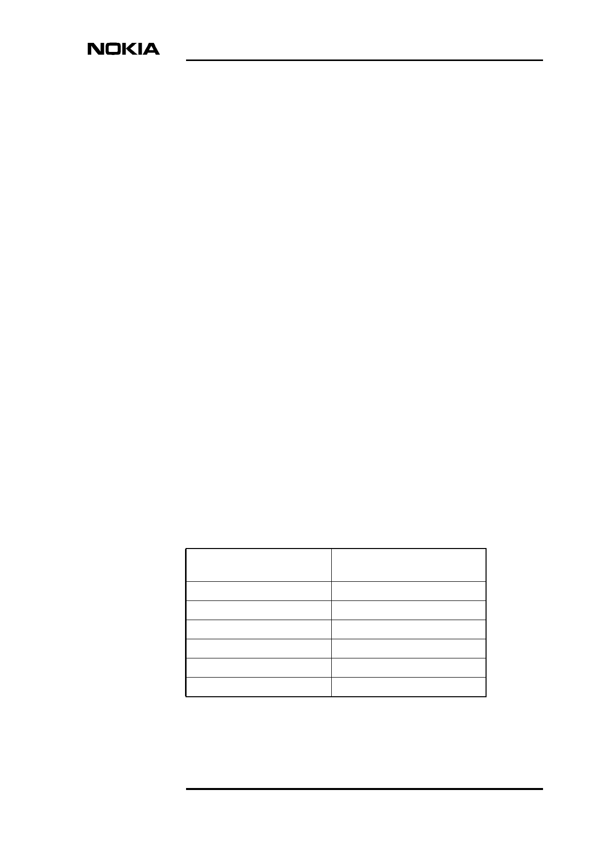
Table shows the contents of Nokia SiteWizard version 3.0. For more information
on the features of the software, see the Software Release Binder delivered with
Nokia SiteWizard.
Included managers and
files Version
BTS Manager 3.0
Site HW configurator 2.0
MetroHub Manager 2.0.5
E1/T1 Manager 3.0.4
RRI Manager 3.0.10
UltraSite BTS Hub Manager C1.2
Commissioning
16 (78) © Nokia Corporation Draft DN999099
Nokia Proprietary and Confidential Issue 4-0 en
Note
2.1.1 Nokia BTS Manager 3.0
Nokia SiteWizard 3.0 contains Nokia BTS Manager version 3.0. This is used for
commissioning the BTS and for carrying out maintenance functions locally at the
BTS.
Nokia BTS Manager provides a graphical user interface to run in a laptop PC in
the Windows environment. See Figure 1 for an example of the graphical user
interface in Windows. The laptop is connected to the BTS via the local
management port (LMP) on the BTS interface unit.
Nokia BTS Manager uses a Commissioning Wizard to guide the user through the
BTS commissioning process. See Table 1 for a description of the Commissioning
Wizard features of Nokia BTS Manager version 3.0.
Nokia BTS Manager also provides a context-sensitive Help.
Hopper Manager 4.2.5
GCS 4.2 (Q1 stack) Service pack 1
SCF Editor 1.0
Included managers and
files Version
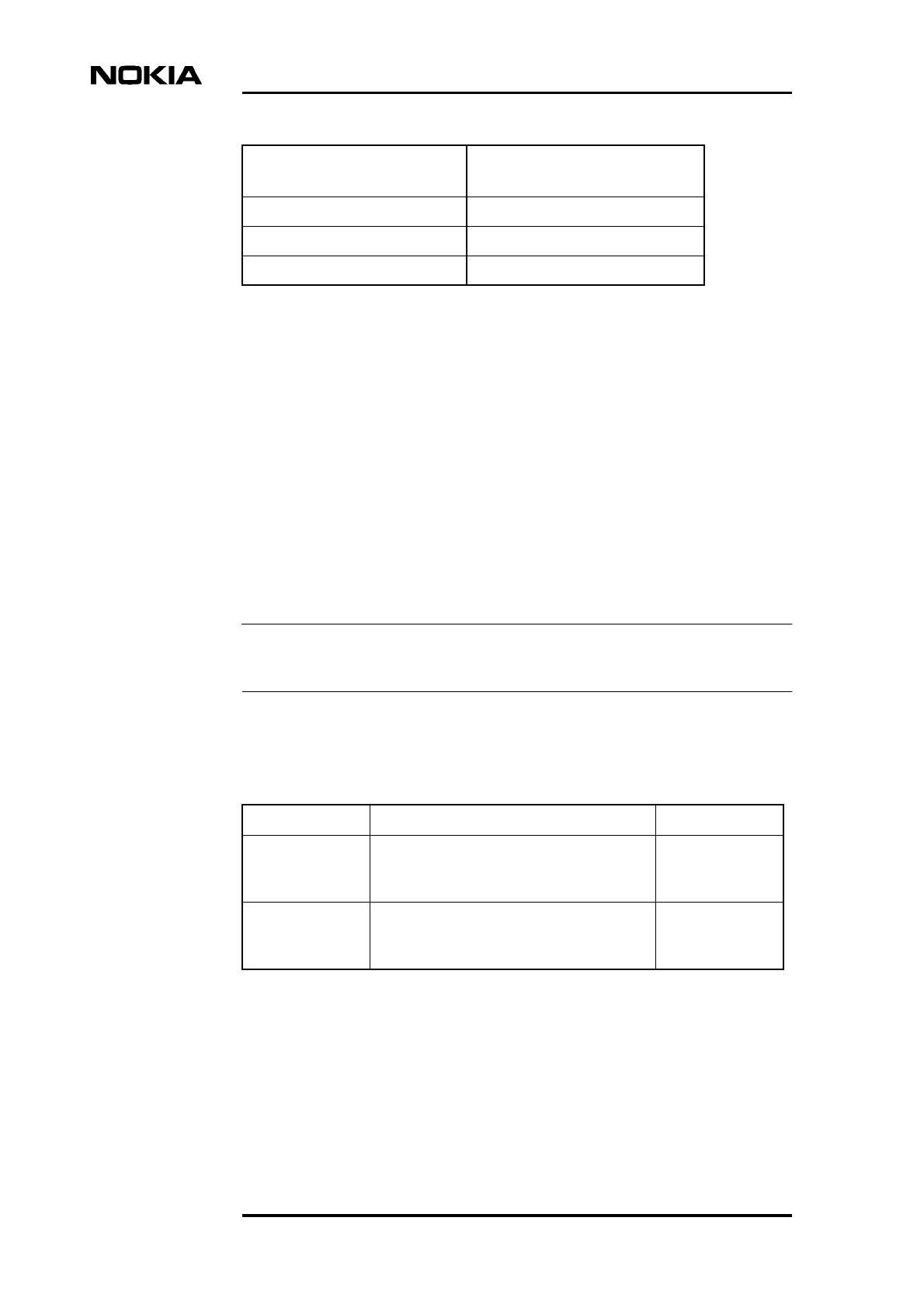
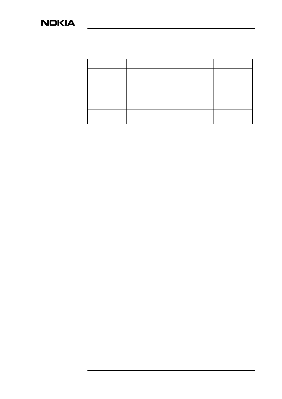
Table 1. Main features of the Commissioning Wizard in Nokia BTS Manager,
version 3.0
Feature Description Reference
LIF and
Synchronisation
settings
For defining line interface and
synchronisation settings according to the
interface unit used.
Chapter 7
Traffic Manager For allocating Abis transmission capacity,
including EDGE dynamic Abis pool (EDAP)
and BTS chaining allocation.
Chapter 6
Commissioning software overview
DN999099 © Nokia Corporation Draft 17 (78)
Issue 4-0 en Nokia Proprietary and Confidential
Radio Wizard For defining external radio units for the
BTS, such as Nokia MetroHopper and
Nokia FlexiHopper.
Chapter 8
Cross-
connections
(E1/T1 Manager)
For setting up cross-connections in
expanded transmission configurations,
such as BTS loop or chain topologies.
Chapter 9
Commissioning
Report
Confirms the actions that have been taken
during the commissioning wizard process.
Chapter 10
Table 1. Main features of the Commissioning Wizard in Nokia BTS Manager,
version 3.0 (Continued)
Feature Description Reference

Commissioning
18 (78) © Nokia Corporation Draft DN999099
Nokia Proprietary and Confidential Issue 4-0 en
Preparing for commissioning
DN999099 © Nokia Corporation Draft 19 (78)
Issue 4-0 en Nokia Proprietary and Confidential
Note
Note
3Preparing for commissioning
Before starting BTS commissioning, complete the following procedure.
Preparing for commissioning:
1. Check that the Abis cables are connected on the BTS.
Commissioning can be performed without the BSC connection (Abis cables
disconnected, for example). For more information, see Step 7 in the
commissioning procedure in Chapter 5.
2. Check that the Nokia MetroSite EDGE Base Station is powered up.
3. Connect the Nokia BTS Manager PC to the BTS’s LMP port. See
Appendix A for a description of the LMP cable.
4. Check that you have the required Site IDs (optional) and transmission
capacity tables.
BTS SW is loaded to the BTS by the manufacturer at the factory. There is no need
to locally load SW to the BTS before commissioning. If the BTS SW is different
from the SW at the BSC, it will be loaded automatically to the BTS during the
commissioning procedure.

Commissioning
20 (78) © Nokia Corporation Draft DN999099
Nokia Proprietary and Confidential Issue 4-0 en
Getting started with BTS Manager
DN999099 © Nokia Corporation Draft 21 (78)
Issue 4-0 en Nokia Proprietary and Confidential
4Getting started with BTS Manager
This chapter gives instructions on how to install, set up and obtain on-line help on
Nokia BTS Manager software. It is assumed that the user knows how to use the
Windows operating system.
When Nokia BTS Manager is installed and set up, the BTS is commissioned by
starting Commissioning Wizard, as described in Chapter 5 of this document.
4.1 Installing Nokia BTS Manager
Nokia BTS Manager is installed on a laptop PC which is connected to the BTS
via the LMP connector on the interface unit.
The installation program creates a Nokia BTS Manager icon on the Windows
desktop and defines the software’s parameters.
For more information on software installation and the system requirements of the
laptop PC, see the Nokia Site Wizard Software Release Binder or the instructions
on the CD-ROM sleeve.
4.2 Setting up Nokia BTS Manager
Start Nokia BTS Manager as follows:
1. Make sure that the BTS Manager laptop is connected to the LMP connector
on the interface unit of the BTS.
2. Double-click the BTS Manager icon on the desktop.
3. Enter the Nokia BTS Manager password. If the password checking option
has not been turned on and it is required, go to FILE | OPTIONS in Nokia
BTS Manager to set up a password (Windows 95/98 environment only).

Commissioning
22 (78) © Nokia Corporation Draft DN999099
Nokia Proprietary and Confidential Issue 4-0 en
Note
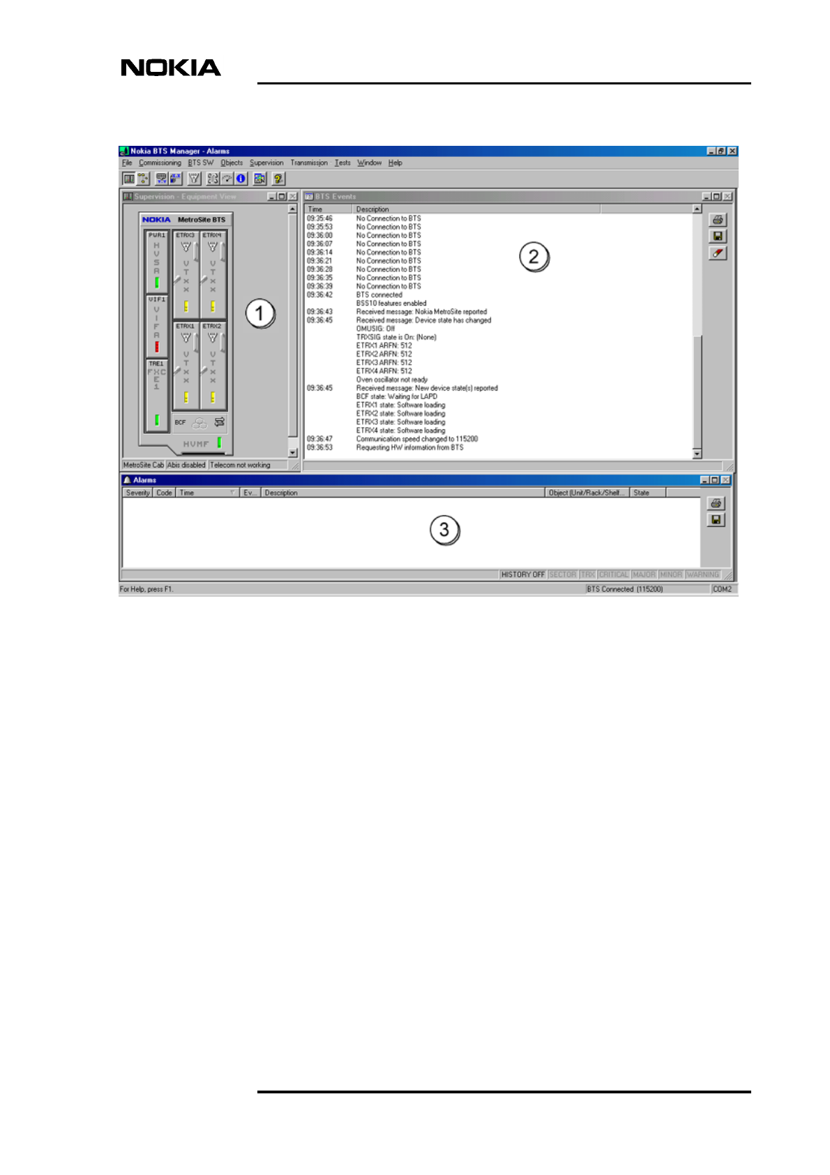
4. Nokia BTS Manager starts with the Supervision - Equipment View (1), BTS
Events (2) and Alarms (3) windows opened (see Figure 1). The software
checks the BTS configuration and represents it graphically it in the Nokia
BTS Manager - Supervision window.
The Nokia BTS Manager PC must be connected to the BTS in order to make BTS
password checking possible. If no connection exists, password checking is not
applicable.
4.2.1 Nokia BTS Manager main windows
The main window of Nokia BTS Manager contains the main menu bar and three
sub-windows, Supervision - Equipment view,BTS Events and Alarms. The main
window and sub-windows are shown in Figure 1. If the sub-windows are not
displayed, see Section 4.2.2 of this document.
Getting started with BTS Manager
DN999099 © Nokia Corporation Draft 23 (78)
Issue 4-0 en Nokia Proprietary and Confidential
Figure 1. Nokia BTS Manager - main window
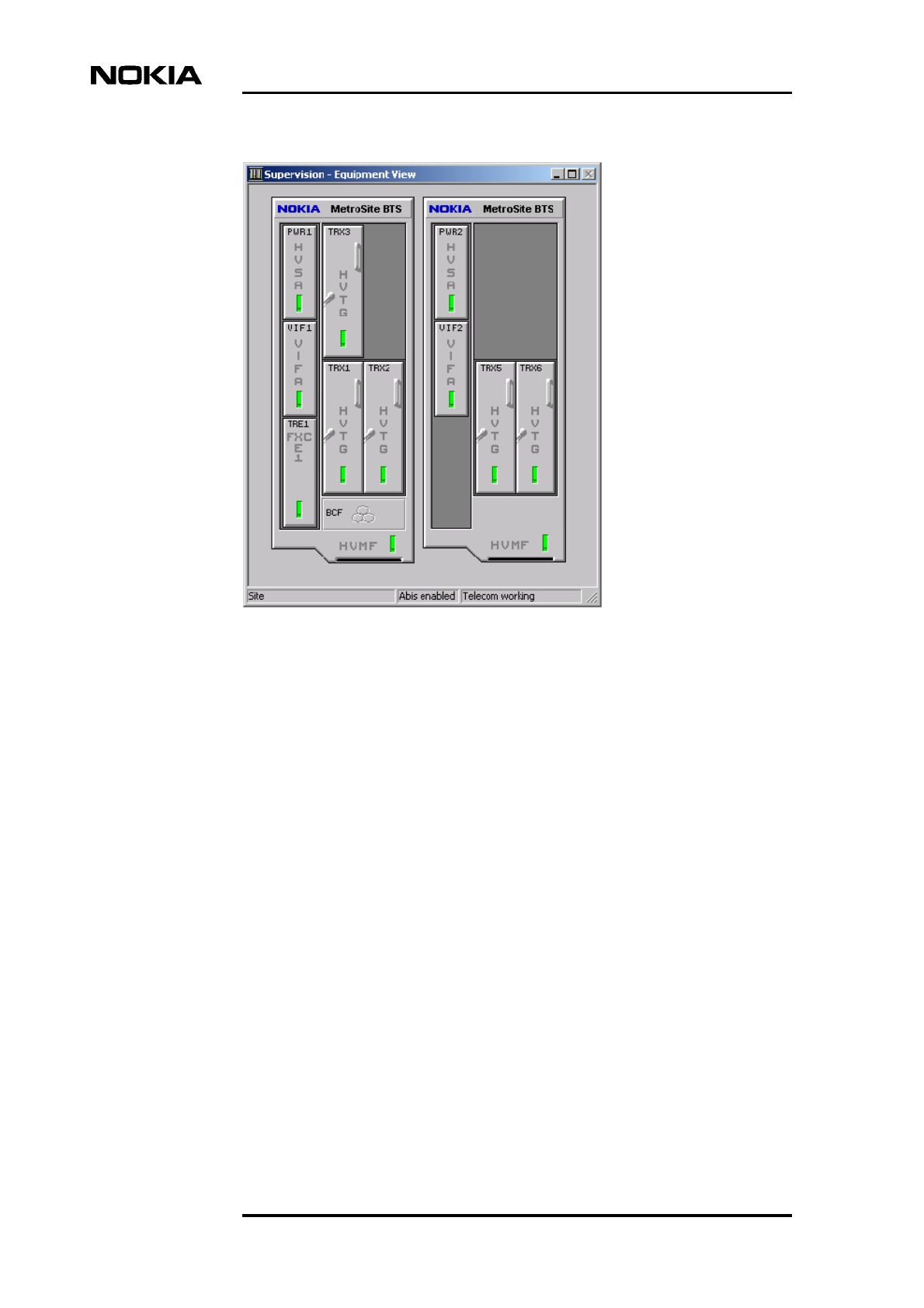
In a BTS chaining configuration, where up to three BTSs are chained as one BCF
object, the Supervision - Equipment View window will appear as shown in Figure
2.
Commissioning
24 (78) © Nokia Corporation Draft DN999099
Nokia Proprietary and Confidential Issue 4-0 en
Figure 2. Supervision - Equipment View window when two MetroSite EDGE
BTSs are chained as one BCF object
4.2.2 Defining Nokia BTS Manager options
If there is no connection to the BTS when starting Nokia BTS Manager, only the
BTS Events window is displayed and some BTS Manager menu options will not
be available. In this case, check the communication parameters. Check also that
the LMP cable is connected to the same COM port that is defined in BTS
Manager.
You can define the different BTS Manager options from FILE | OPTIONS.
4.3 Nokia BTS Manager Help
Nokia BTS Manager has a convenient, context-sensitive on-line Help facility for
getting information about a task you are going to perform, a feature you might
want to know more about, or a command you may want to use.
To get Help, do one of the following:

Getting started with BTS Manager
DN999099 © Nokia Corporation Draft 25 (78)
Issue 4-0 en Nokia Proprietary and Confidential
Note
• Press F1.
• Select the HELP menu from the main toolbar.
• Click the HELP button in any of the dialogue boxes.
In the Help Topics window you will see three tabbed pages: Contents,Index and
Find.
Contents
The Contents page displays a list of topics organised into books by category.
Because the BTS Manager supports both MetroSite and InSiteTM base stations,
there are separate Operating and Reference books for the two types of BTS.
Index
The Index page lists keywords in alphabetical order through which different
topics can be reached.
Find
The Find page provides a full-text search functionality that allows you to search
for any word or phrase in the Help file.
To exit Help, press the ESC key or ALT+F4 on the PC keyboard.
If the BTS is connected, the Help topics for the Transmission Unit Manager are
also available on the HELP menu.

Commissioning
26 (78) © Nokia Corporation Draft DN999099
Nokia Proprietary and Confidential Issue 4-0 en
Commissioning Wizard process
DN999099 © Nokia Corporation Draft 27 (78)
Issue 4-0 en Nokia Proprietary and Confidential
Note
5Commissioning Wizard process
Commissioning is done with Nokia BTS Manager’s Commissioning Wizard.
It is assumed here that the site has been created at the BSC (LAPD links created
and PCM port active). If the site is newly created, the BCF is in the ‘locked’ state.
5.1 How to use Commissioning Wizard
Commissioning Wizard guides you through the commissioning process with a
series of wizard pages. Each wizard page contains data entry fields or paths to
dialogue boxes for data entry. When the settings on each wizard page are set up
according to your requirements, move to the next stage of the wizard with the
NEXT command, as described in the procedure in Section 5.2.
If you need to go back and change settings while in the wizard, click BACK. To
stop the commissioning without saving any of the settings, click CANCEL. Click
the HELP button on any wizard page to get a pop-up Help window.
When starting commissioning, the BCF object in the Supervision - Equipment
View window displays the ‘BCF is commissioning’ symbol (see Figure 3). You
can also check the operational state of the BCF by moving the mouse pointer over
the BCF symbol in the Supervision - Equipment View window, clicking the right
mouse button and selecting the BCF Properties command.
Figure 3. ‘BCF is commissioning’ symbol

Commissioning
28 (78) © Nokia Corporation Draft DN999099
Nokia Proprietary and Confidential Issue 4-0 en
5.2 Commissioning with Commissioning Wizard
To commission the BTS, follow the steps in the procedure below. You will be
asked to refer to other sections in this document for some operations in the
procedure, after which you should return to this main procedure.
Commissioning with Commissioning Wizard:
1. Start Nokia BTS Manager 3.0 on your laptop.
2. In BTS Manager, choose the COMMISSIONING | WIZARD command
from the main menu. The BTS Commissioning Wizard window appears.
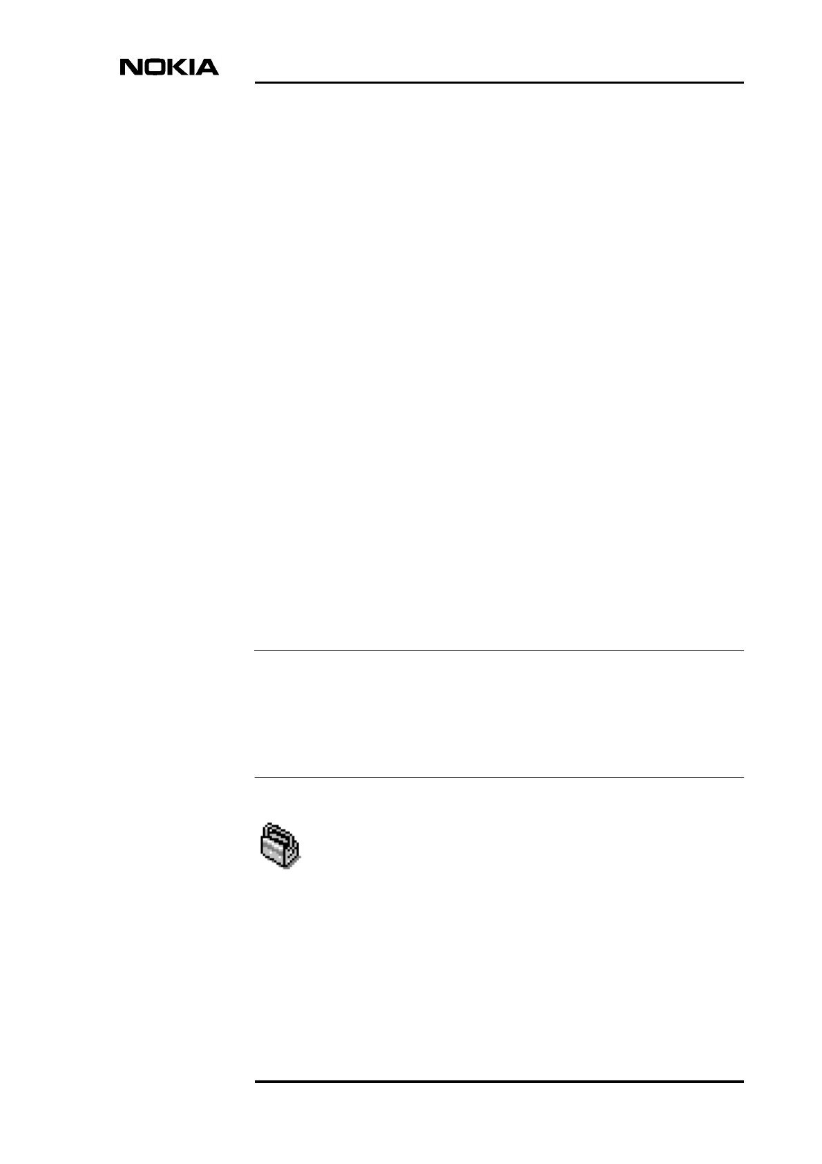
3. Commissioning can only be done with a non-commissioned BTS. If the
BTS is already commissioned, select ‘Undo Commissioning’ and NEXT in
the BTS Commissioning Wizard window (this would be the only option
available in Commissioning Wizard). The BTS will be un-commissioned
and the ‘Manual Commissioning’ option will then appear in the BTS
Commissioning Wizard window.
To commission the BTS, select ‘Manual Commissioning’ in the BTS
Commissioning Wizard window and click NEXT (see Figure 4).
Commissioning Wizard process
DN999099 © Nokia Corporation Draft 29 (78)
Issue 4-0 en Nokia Proprietary and Confidential
Figure 4. Opening window of BTS Manager’s Commissioning Wizard
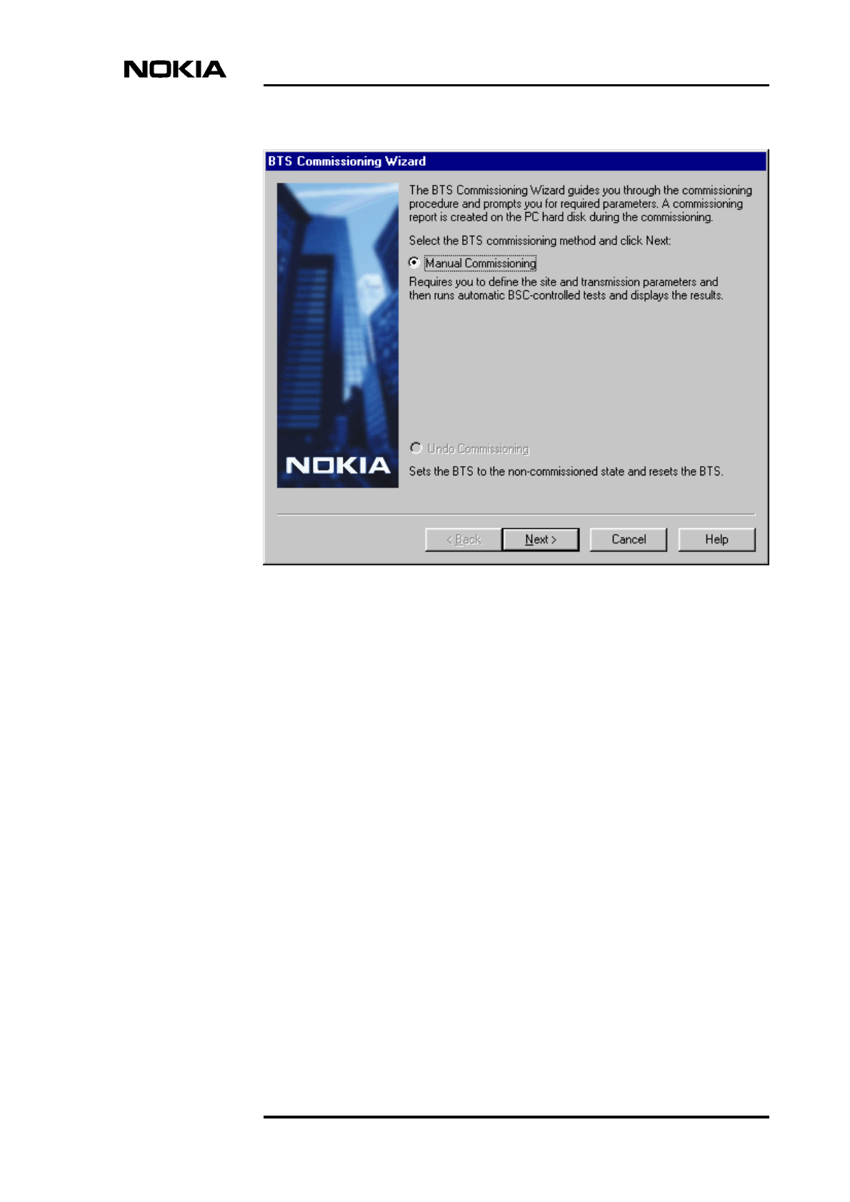
4. Enter the parameters on the Set Transmission Parameters wizard page (see
Figure 5). All parameters on this page are optional. They appear in the
Commissioning Report, but the BTS does not compare them with the
corresponding parameters defined at the BSC.
Click LIF SETTINGS to check the line interface settings. Modify the
settings, if necessary, and click OK. See Chapter 7.1 for more information.
Commissioning
30 (78) © Nokia Corporation Draft DN999099
Nokia Proprietary and Confidential Issue 4-0 en
Note
Note
Figure 5. The Set Transmission Parameters wizard page of Nokia BTS
Manager’s Commissioning Wizard
Click SYNCHRONIZATION to check the synchronization settings.
Modify the settings, if necessary, and click OK. See Chapter 7.2 for more
information.
There are no synchronization settings for the FC RRI unit because the only
available timing option for that unit is Rx Clock. If the transmission unit in the
BTS configuration is FC RRI and you click the Synchronization button, a check
mark appears in the ‘Checked’ check box, and the NEXT button becomes enabled
(if you have already checked the LIF settings).
The NEXT button remains disabled until you have checked the LIF and
synchronization settings.
Click NEXT after you have checked the parameters.
Commissioning Wizard process
DN999099 © Nokia Corporation Draft 31 (78)
Issue 4-0 en Nokia Proprietary and Confidential
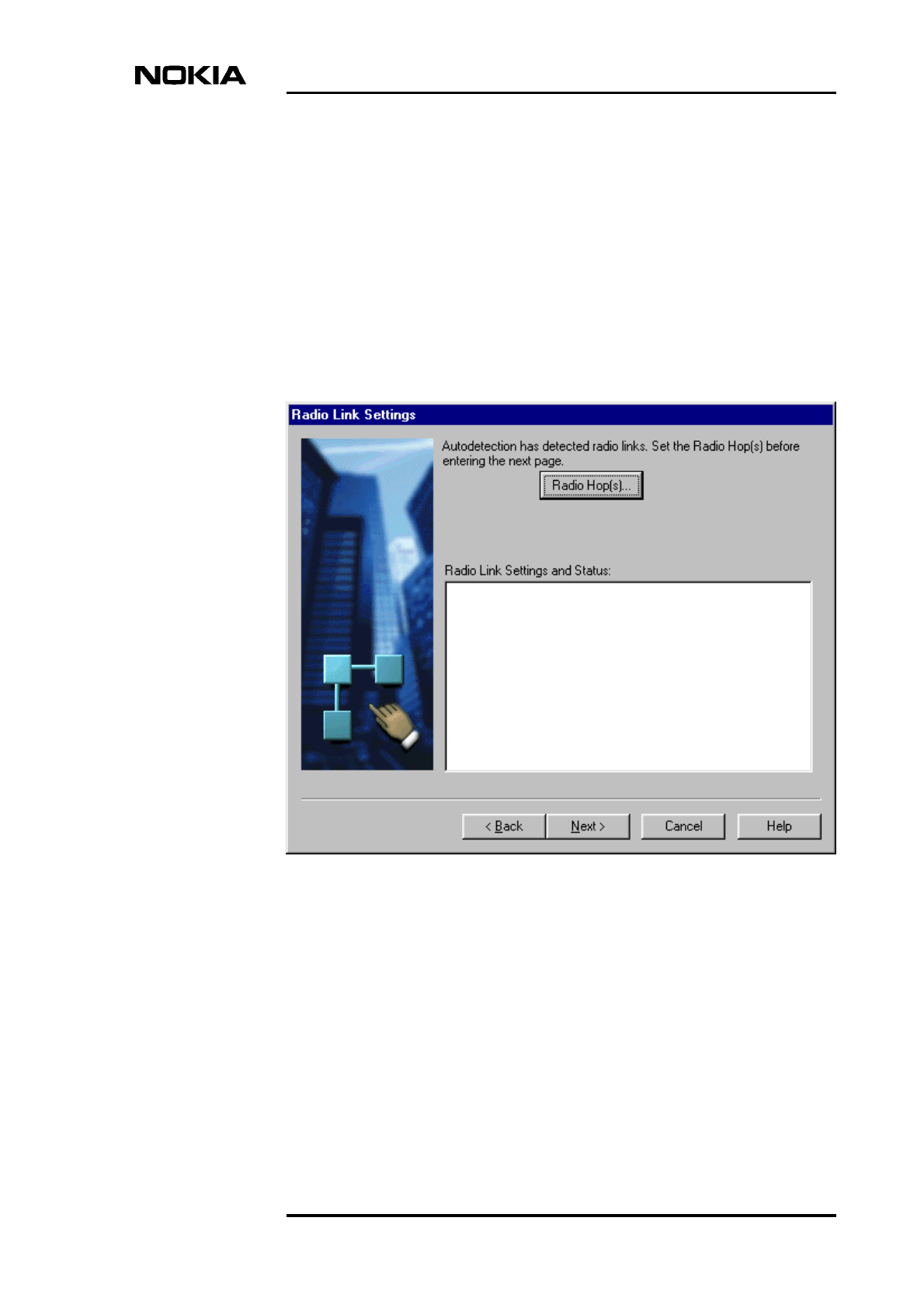
5. The Radio Links Settings wizard page appears if BTS Manager detects an
F(X)C RRI transmission unit in the BTS configuration (see Figure 6). If
there are no radios in the BTS configuration and this wizard page does not
appear, proceed directly to the next step in this procedure.
Click the RADIO HOP(S) button to launch the Radio Wizard (from the
radio transmission unit manager) and check or adjust the radio hop
parameters. The signal quality can also be checked when making these
adjustments in the Radio Wizard. Refer to Chapter 8 for instructions on
using the Radio Wizard.
When the radio links are ready, click NEXT to proceed.
Figure 6. Radio link settings in Nokia BTS Manager’s Commissioning Wizard
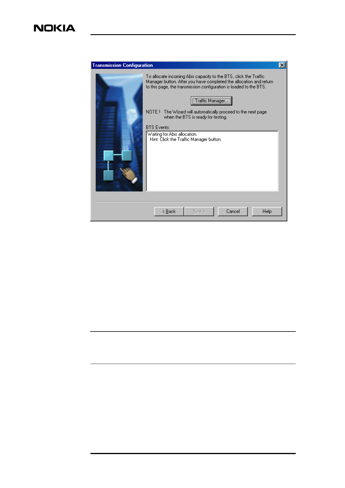
6. To allocate incoming Abis capacity to the BTS, click the TRAFFIC
MANAGER button in the Transmission Configuration window (see Figure
7) to open . For information on how to allocate the transmission capacity,
see Chapter 6.
Commissioning
32 (78) © Nokia Corporation Draft DN999099
Nokia Proprietary and Confidential Issue 4-0 en
Note
Figure 7. Opening Traffic Manager from Commissioning Wizard
When you have completed the allocation in Traffic Manager and you return
to this wizard page, the BACK button is disabled because the transmission
configuration has been loaded to the BTS and the transmission connection
is established between the BTS and the BSC. If the connection fails, see
Chapter 11 of this document, ‘Troubleshooting and fault reporting’.
If you need to change any of the parameters you have specified prior to this
point, click CANCEL, run the ‘Undo Commissioning’ procedure and then
re-commission the BTS with the correct parameters.
Commissioning Wizard will automatically proceed to the next wizard page after
you have allocated the incoming Abis capacity and the BTS is ready for testing.
7. Depending on the status of the Abis connection, proceed either from Abis
connected or Abis not connected.
1. Abis connected:
Commissioning Wizard process
DN999099 © Nokia Corporation Draft 33 (78)
Issue 4-0 en Nokia Proprietary and Confidential
During the BTS/BSC start-up scenario the BSC checks the BTS SW
and if it is not the correct one, the BSC loads SW to the BTS. This
loading will take from 5 to 20 minutes, depending on the OMUSIG
link speed. If no SW loading takes place, the process will take about
10 seconds.
If SW loading takes place, the BCF is in the ‘SW loading’ state
during the SW loading operation. This information is shown on the
BTS Events list. When the SW loading from the BSC is completed,
the BCF is reset automatically. This means that the Supervision -
Equipment View disappears for a few seconds, but after the BTS has
started normally, the commissioning procedure continues
automatically.
After the SW checking and/or loading, the BSC sends the
configuration data to the BTS and the BCF enters the ‘Configuring’
state. It can take up to five minutes for the oven oscillator to warm
up after the BTS is powered on. The BTS Events window displays a
message when the oven oscillator is ready.
When the BTS is ready for testing, the Wizard automatically
proceeds to the next wizard page and the BSC runs automatic tests
on the Abis link and on each TRX installed in the BTS.
The Abis loop test will take about two minutes (all channels of all
TRXs are tested).
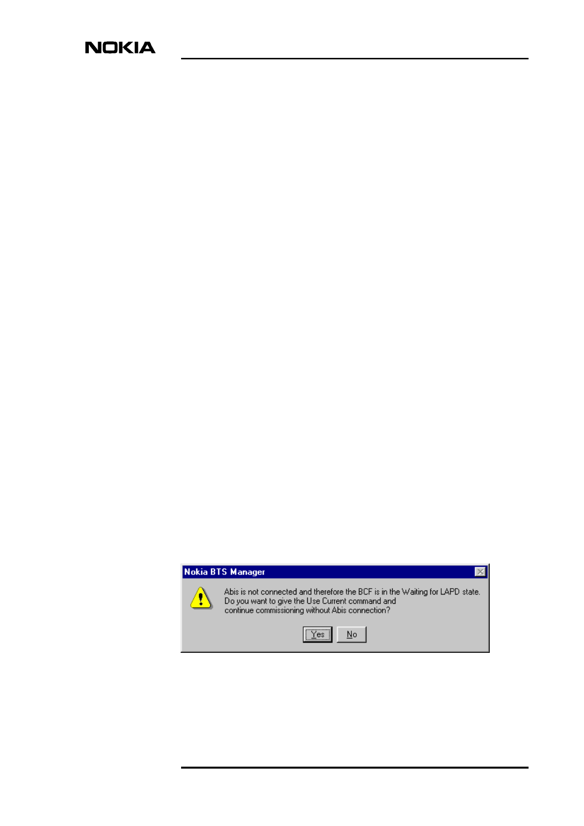
2. Abis not connected:
If the establishment of the BTS/BSC connection does not succeed
(Abis cables are not connected, for example), the BCF remains in the
‘Waiting for LAPD’ state. If you now click NEXT, the Wizard
displays a message (see Figure 8). The message also asks you if you
want to give the ‘Use Current’ command. If you click YES in the
dialogue box, the BTS starts to use the BTS SW in the master TRX
memory and the Wizard proceeds to the BTS Test Reporting wizard
page after TRX and BCF achieve the ‘Configuring’ state. If you
click NO in the dialogue box, the BCF remains in the ‘Waiting for
LAPD’ state until you connect the Abis cables.
Figure 8. The Abis not connected dialogue box
Commissioning
34 (78) © Nokia Corporation Draft DN999099
Nokia Proprietary and Confidential Issue 4-0 en
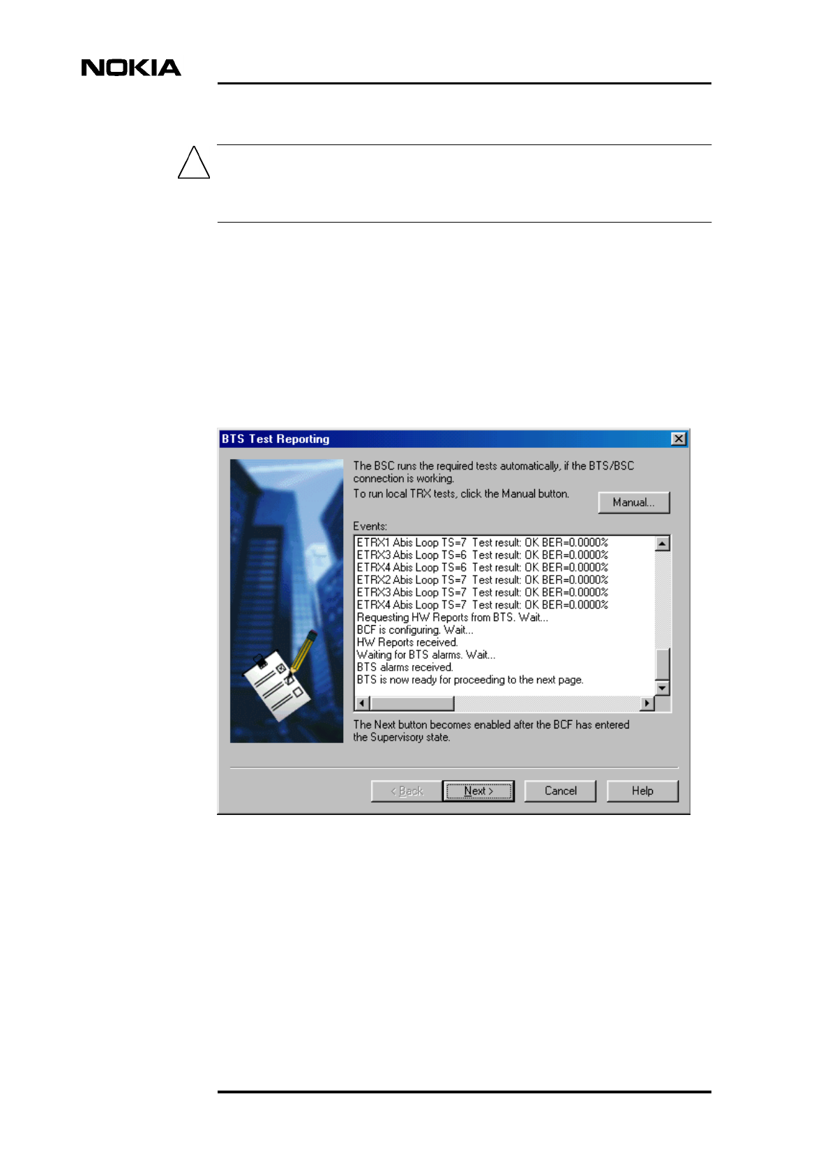
Caution
In order not to interfere with the operation of other sites, make sure that an RF
load is connected to every TRX in the BTS before you start local TRX tests.
8. If Abis is connected, the BTS Test Reporting wizard page displays the test
results (see Figure 9). Check the results in the ‘Events’ list.
Whether or not Abis is connected, BTS Manager requests HW reports from
the BTS. The ‘Events’ list will display any alarms 10 seconds after the BCF
has entered the ‘Supervisory’ state. The NEXT button becomes enabled at
this point.
Click NEXT to proceed to EAC input settings.
Figure 9. BTS test events
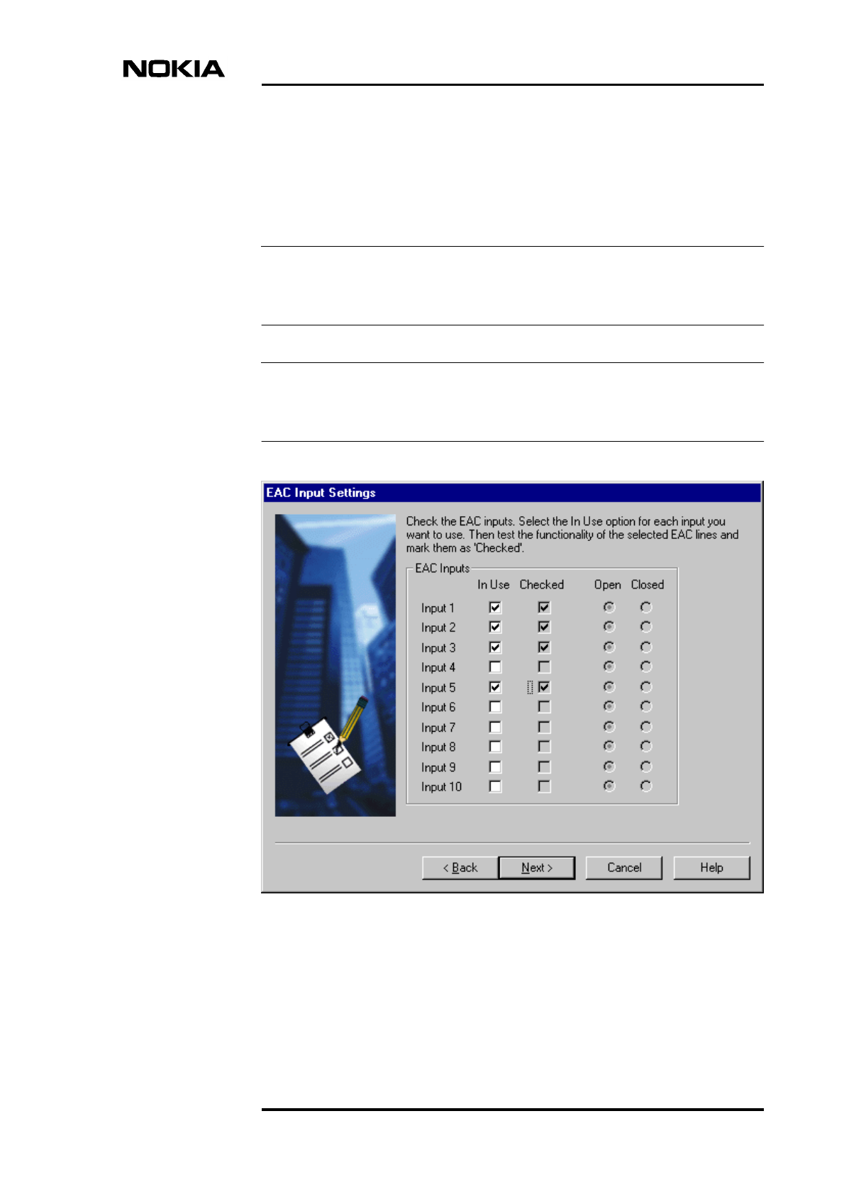
9. On the EAC Input Settings wizard page (Figure 10), select the required
EACs as ‘In Use’ by marking the checkboxes and then test their
functionality in real time.
Commissioning Wizard process
DN999099 © Nokia Corporation Draft 35 (78)
Issue 4-0 en Nokia Proprietary and Confidential
Note
Note
The state of each EAC will change in real time as you test it the alarm.
Then, the appropriate state changes from ‘Open’ to ‘Closed’, or vice versa.
After testing the EACs, mark them as ‘Checked’. When you have
completed the testing, click NEXT.
If the EAC inputs will not be used, just click NEXT without marking any
checkboxes.
The NEXT button remains disabled until you click a check mark in the ‘Checked’
check box for all inputs that are ‘In Use’.
Figure 10. Setting and testing EAC inputs in real time
Commissioning
36 (78) © Nokia Corporation Draft DN999099
Nokia Proprietary and Confidential Issue 4-0 en
Note
Note
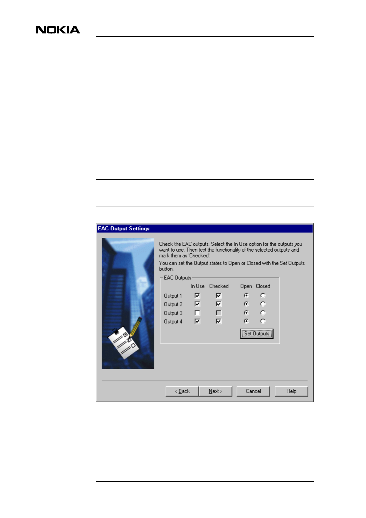
10. On the EAC Output Settings wizard page (Figure 11), test the required EAC
outputs by ticking the ‘In use’ check box and testing the functionality of the
outputs in real time. Mark tested outputs as ‘Checked’.
When you have finished the EAC output settings, click the SET OUTPUTS
button to send the information to the BTS.
After you have completed the required EAC output settings, click NEXT.
The NEXT button remains disabled until you click a check mark in the ‘Checked’
check box for all outputs that are ‘In Use’.
The EAC names and polarities are defined at the BSC.
Figure 11. Setting and testing EAC outputs in real time
Commissioning Wizard process
DN999099 © Nokia Corporation Draft 37 (78)
Issue 4-0 en Nokia Proprietary and Confidential
Note
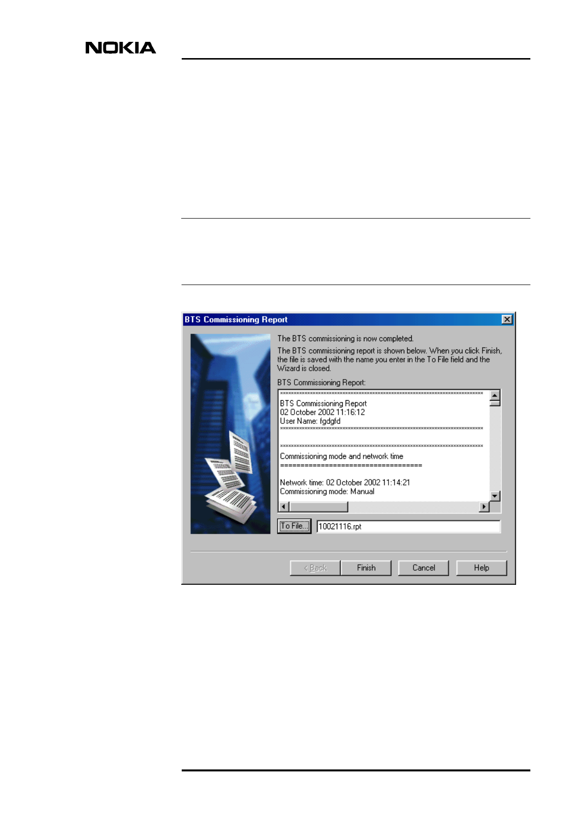
11. The BTS Commissioning Report wizard page appears (see Figure 12).
Check the BTS Commissioning Report.
12. Save the BTS Commissioning Report to the your BTS Manager laptop by
typing a path and a file name for the report in the ‘To File’ field, or clicking
TO FILE and then BROWSE to specify the path and file name.
If you do not save the report in this way, it will be automatically saved to
your laptop’s Windows desktop when you finish the commissioning.
The BTS Commissioning Report is generated only at this point of the
commissioning procedure. If you click CANCEL, the report is not saved and it
cannot be generated anywhere else for this site.
Figure 12. BTS Commissioning Report summary window

Commissioning
38 (78) © Nokia Corporation Draft DN999099
Nokia Proprietary and Confidential Issue 4-0 en
Note
Note
Note
13. Click FINISH. The BTS Commissioning Report is saved to the location
you have specified or automatically to your laptop’s Windows desktop.
Commissioning Wizard is now closed. See Chapter 10 for more details on
the Commissioning report.
If there is a need to route transmission capacity, the cross-connections have to be
created manually. See Chapter 9 for instructions on how to create the cross-
connections.
For maintenance purposes, in the case of a BTS with only one TRX, it is
recommended to make a back-up copy of the time-slot allocation settings using
the Traffic Manager’s export function (see Section 6).
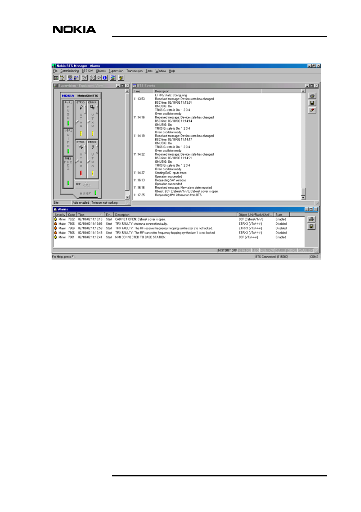
At this point you should check the Alarms window in the main Nokia BTS
Manager - Supervision window for possible alarms generated during
commissioning. Figure 13 shows an example of a major alarm, which must
be cleared. The minor alarms (cover open and MMI connected) are cleared
when the BTS commissioning procedure is completed.
For alarm descriptions, see Nokia MetroSite EDGE Base Station Alarm
Descriptions.
For future maintenance purposes, it is recommended that you export the cross-
connection information of the FXC E1/T1 transmission unit to a file. For
instructions, see the section called ‘Replacing the transmission unit’ in Nokia
MetroSite EDGE Base Station Maintenance.
Commissioning Wizard process
DN999099 © Nokia Corporation Draft 39 (78)
Issue 4-0 en Nokia Proprietary and Confidential
Figure 13. Example of a major alarm reported in Nokia BTS Manager
14. If the site was newly created at the BSC, it remains in the ‘locked’ state
after commissioning. If the site is locked at the BSC, the TRXs remain in
the ‘Waiting for system information’ state. The TRX objects in the
Supervision - Equipment View window have the ‘Waiting for system
information’ symbol (see Figure 14). You can also check the operational
states of the TRXs by moving the mouse pointer over a TRX in the
Supervision - Equipment View window, clicking the right mouse button
and selecting the TRX PROPERTIES command.
Request a ‘site unlock’, including TRXs, from the BSC or NMS. After the
‘site unlock’, the BCF is reset automatically and all units enter the
‘supervisory’ state (the LEDs are green).

Commissioning
40 (78) © Nokia Corporation Draft DN999099
Nokia Proprietary and Confidential Issue 4-0 en
Figure 14. ‘Waiting for system information’ symbol
15. Exit Nokia BTS Manager from FILE | EXIT on the main menu bar.
16. Disconnect the BTS Manager PC from the LMP port of the Nokia
MetroSite EDGE Base Station.
Refit the BTS cover, as described in the document, Nokia MetroSite EDGE
Base Station Installation.
The commissioning parameters are stored in the flash memory of the master TRX
(TRX 1). The master TRX creates backup copies of these parameters in the slave
TRXs’ flash memory.
Traffic Manager
DN999099 © Nokia Corporation Draft 41 (78)
Issue 4-0 en Nokia Proprietary and Confidential
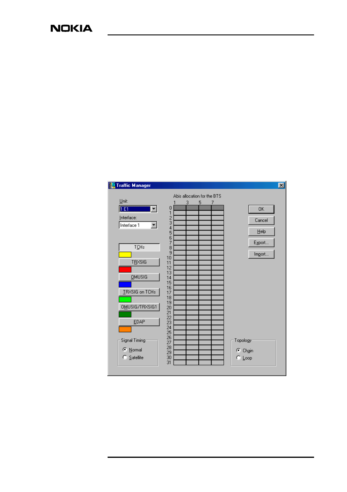
6Traffic Manager
Traffic Manager is a graphical user interface tool for allocating BTS transmission
capacity, irrespective of which Nokia MetroSite transmission unit is used. With
Traffic Manager, you can define the line interface (Port 1, for example) and the
incoming time-slot allocation on the Abis according to your transmission plan.
Figure 15 shows an unallocated BTS.
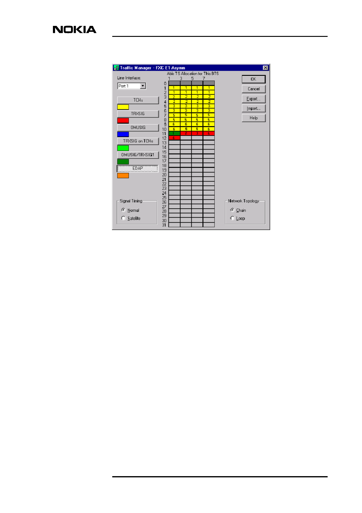
Figure 15. Opening window for Traffic Manager, an unallocated BTS
Commissioning
42 (78) © Nokia Corporation Draft DN999099
Nokia Proprietary and Confidential Issue 4-0 en
Note
With an FXC transmission unit, the cross-connections to this BTS are created
automatically after the capacity has been set and approved.
The capacity to be used is defined by selecting its signal type (TCHs, TRXSIG,
OMUSIG, TRXSIG on TCHs or OMUSIG/TRXSIG) and by reserving required
time slots and bits. The signal types are explained in more detail in Section 6.2.
In the case of 1.5 MB links (T1), the Traffic Manager automatically reduces the
number of time-slot rows in the table to 24.
With EDGE transmission, the dynamic Abis feature is used to improve the
efficient the use of transmission resources. This requires allocation of the EGPRS
dynamic Abis pool (EDAP) between the available EDGE TRXs in a BTS or BTS
chain.
6.1 Allocating transmission capacity
Transmission allocation capacity and dynamic Abis are both allocated from the
Traffic Manager window.
6.1.1 Allocating Abis transmission capacity
Allocate Abis transmission capacity as follows:
1. Select the line interface used (Port 1 - Port 16, depending on the
transmission unit). With an FC E1/T1 transmission card, the only possible
option is Port 1.
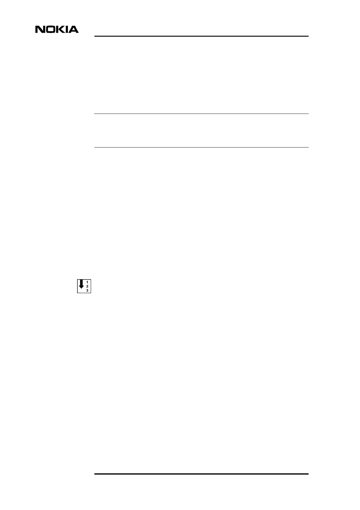
2. Click the TCHs button and then click in a cell in the ‘Abis TS Allocation
for this BTS’ table to allocate time-slots. Repeat this step to allocate
transmission capacity to all TRXs in the BTS. See Figure 16 for an example
of allocating transmission capacity to a TRX.
Traffic Manager
DN999099 © Nokia Corporation Draft 43 (78)
Issue 4-0 en Nokia Proprietary and Confidential
Figure 16. Allocating transmission capacity to TRXs
From here onwards, you can choose one of three alternative ways to
proceed.
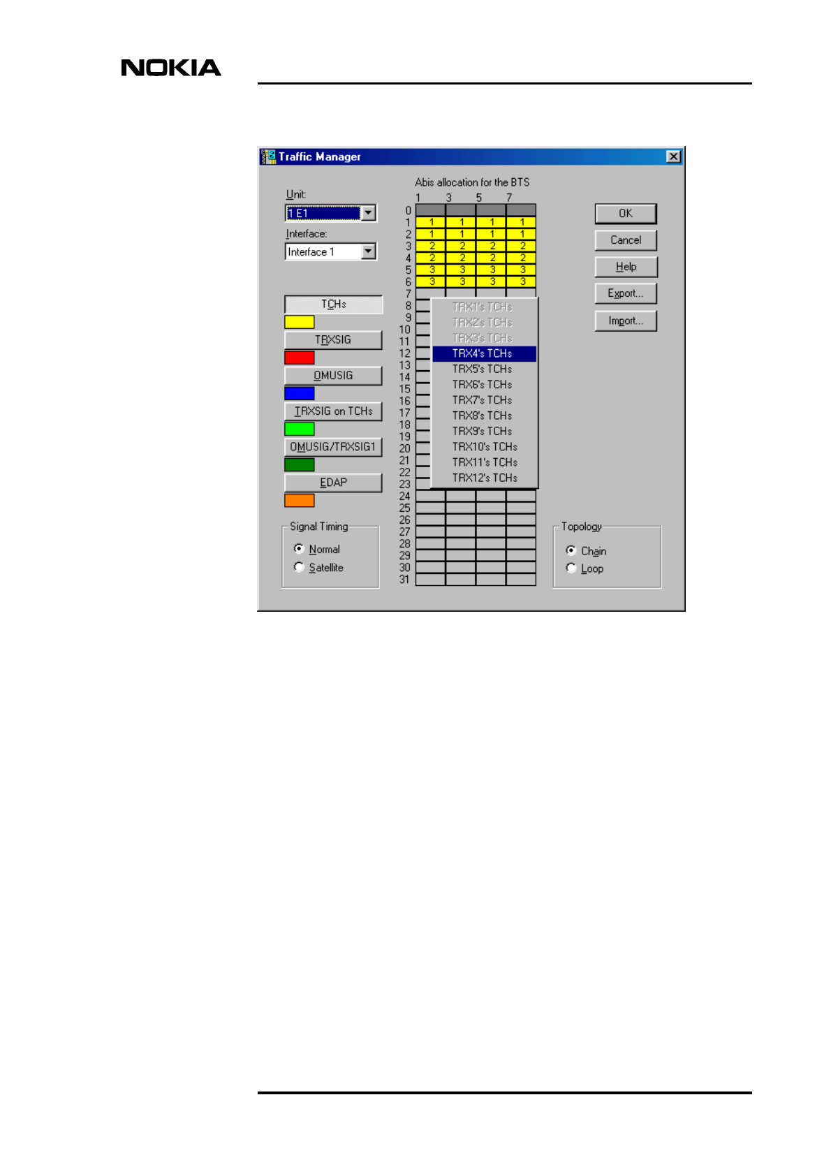
3. Alternative 1.
Click the TRXSIG button and then click the first bit in a time-slot in the
Abis allocation table. Select the link speed from the pop-up menu. Repeat
for all TRXs in the BTS configuration. Click the OMUSIG button and then
click a cell in the Abis allocation table. Select the link speed from the pop-
up menu. Figure 17 shows an example of a completed allocation.
Commissioning
44 (78) © Nokia Corporation Draft DN999099
Nokia Proprietary and Confidential Issue 4-0 en
Figure 17. Example of a completed allocation in Traffic Manager
Alternative 2.
Click the TRXSIG on TCHs button and then click the first bit in a time-slot
you reserved for TCHs in Step 2. Select the link speed from the pop-up
menu. Repeat for all TRXs in the BTS configuration. Click the OMUSIG
button and then click a cell in the Abis allocation table. Select the link
speed from the pop-up menu.
Alternative 3.
Click the OMUSIG/TRXSIG1 button and then click the first bit in the
TCHs allocation for TRX 1. Select the link speed from the pop-up menu.
Click the TRXSIG or TRXSIG on TCHs button and allocate TRXSIG
capacity for the other TRXs in the BTS configuration.

Traffic Manager
DN999099 © Nokia Corporation Draft 45 (78)
Issue 4-0 en Nokia Proprietary and Confidential
Note
4. If EDGE transmission is not required, proceed directly to Section 6.1.4 to
complete the Abis transmission allocation.
For EDGE transmission, proceed to Section 6.1.3 to allocate EDGE TRXs
to the dynamic Abis pool.
For chained BTS transmission allocation, proceed to Section 6.1.2.
6.1.2 Allocating transmission capacity for chaining
The chaining feature is available for BTSs which have been loaded with CX 3.0
software or later. Two or three Nokia MetroSite EDGE BTSs can be chained
together as one BCF object.
For example, a chain of two BTSs might contain five TRXs, as seen in the
example of BTS Manager’s Supervision - Equipment View window in Figure 2.
The transmission capacity can be allocated between the TRXs in the chained
BTSs, as described in the procedure below. BTS Manager is connected to the
master BTS in the chain.
Before beginning a site expansion, the site must be locked from the BSC or NMS
with BCF lock.
You can check if the site has been locked by connecting a BTS Manager laptop
to the master BTS in the chain, starting BTS Manager and checking TRX
PROPERTIES in the Supervision - Equipment View window (right-click with the
mouse over a TRX in the window).

Commissioning
46 (78) © Nokia Corporation Draft DN999099
Nokia Proprietary and Confidential Issue 4-0 en
Note
Allocate transmission capacity for chaining as follows:
If the FXC type transmission unit replaced an FC type transmission unit during a
BTS upgrade for chaining, or if CX 3.0 software (or later) is not loaded at the
BTS, the site must be uncommissioned and then re-commissioned before
allocating transmission capacity for the BTS chain.
With BTS Manager, uncommission the master BTS by selecting
COMMISSIONING | WIZARD from the main menu and selecting the ‘Undo
Commissioning’ button. Make sure that CX 3.0 or later is loaded at the BSC or
NMS and start Commissioning Wizard again, as described earlier in this manual.
1. Select the line interface used (Port 1 - Port 16, depending on the
transmission unit). An FXC type transmission unit is required for chaining.
2. Click the TCHs button and then click in a cell in the ‘Abis TS Allocation
for this BTS’ table to allocate time-slots to a TRX. Repeat this step to
allocate transmission capacity to all TRXs in the BTS chain (up to 12 TRXs
are possible in a chained configuration).
In the example shown in Figure 18, there are five TRXs in two BTS
cabinets. TRXs 1, 2, and 3 are in the first BTS and TRXs 5 and 6 are in the
second BTS in the chain.
From here onwards, you can choose one of three alternative ways to
proceed.
Alternative 1.
Click the TRXSIG button and then click the first bit in a time-slot in the
Abis allocation table. Select the link speed from the pop-up menu. Repeat
for all TRXs in the BTS configuration. Click the OMUSIG button and then
click a cell in the Abis allocation table. Select the link speed from the pop-
up menu.
Traffic Manager
DN999099 © Nokia Corporation Draft 47 (78)
Issue 4-0 en Nokia Proprietary and Confidential
Figure 18. Example of traffic allocation for five TRXs in a two BTS chain
Alternative 2.
Click the TRXSIG on TCHs button and then click the first bit in a time-slot
you reserved for TCHs in Step 2. Select the link speed from the pop-up
menu. Repeat for all TRXs in the BTS configuration. Click the OMUSIG
button and then click a cell in the Abis allocation table. Select the link
speed from the pop-up menu.
Alternative 3.
Click the OMUSIG/TRXSIG1 button and then click the first bit in the
TCHs allocation for TRX 1. Select the link speed from the pop-up menu.
Click the TRXSIG or TRXSIG on TCHs button and allocate TRXSIG
capacity for the other TRXs in the BTS configuration.
3. If EDGE transmission is not required, proceed directly to Section 6.1.4 to
complete the Abis transmission allocation. For EDGE transmission,
proceed to Section 6.1.3to allocate EDGE TRXs to the dynamic Abis pool
(EDAP).
Commissioning
48 (78) © Nokia Corporation Draft DN999099
Nokia Proprietary and Confidential Issue 4-0 en
Note
6.1.3 Allocating for EDGE dynamic Abis transmission
Dynamic Abis uses the EGPRS dynamic Abis pool (EDAP) to efficiently allocate
transmission resources for the higher EDGE data rates.
EDAP resources are shared between EDGE TRXs in a single BTS, chained BTSs,
or cross-connected BTSs. The available TRXs are allocated in Traffic Manager
from the EDAP command.
Allocate TRXs to the EDAP as follows:
1. Select the incoming line interface port according to the transmission unit
used and then click the EDAP button.
2. Select the start time-slot by clicking with the mouse. Drag the mouse to the
end time-slot and release. The EDAP Properties dialogue box is opened
(see Figure 19).
The EDAP Properties dialogue box appears automatically when you have
selected more than 11 available timeslots.
Figure 19. Starting EDAP time-slot selection
Traffic Manager
DN999099 © Nokia Corporation Draft 49 (78)
Issue 4-0 en Nokia Proprietary and Confidential
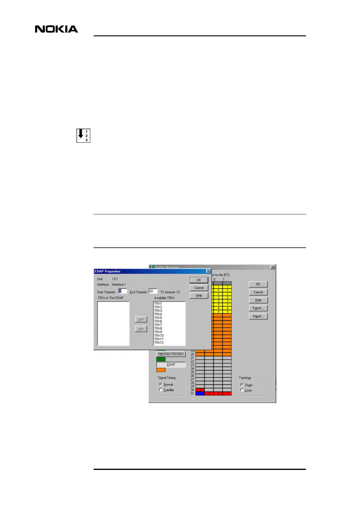
3. In EDAP Properties, select the available TRXs from the list and move
them to the ‘TRXs in this EDAP’ list by clicking on the <<< button. See
Figure .
Figure 20. Example of allocating EDGE TRXs for dynamic Abis
4. If the EDAP is to be shared with other BTSs in a cross-connection, select
the outgoing interface port in the ‘Outgoing interfaces for this EDAP’ box.
See Figure 21 for an example of this part of the EDAP Properties window
(this only appears if cross-connections are being used).
For more information on cross-connections, see Chapter 9 of this
document.
Figure 21. Selecting the interface for EDAP allocation in a cross-connected
BTS configuration
Commissioning
50 (78) © Nokia Corporation Draft DN999099
Nokia Proprietary and Confidential Issue 4-0 en
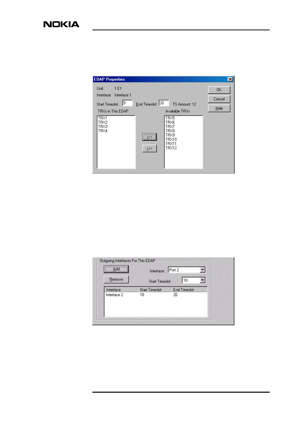
5. Click OK to return to the main Traffic Manager window. Figure 22 shows
the resulting traffic allocation for this example.
Figure 22. Example of the traffic allocation with EDAP for EDGE transmission
6. To complete the allocation, proceed to Section 6.1.4.
6.1.4 Completing the transmission allocations
Set the transmission allocation in the BTS as follows:
1. Check that the signal timing is correctly set (either ‘Normal’ or ‘Satellite’).
At this point you can click the EXPORT button to export the Abis time-slot
allocation information to a file for future maintenance purposes.
Traffic Manager
DN999099 © Nokia Corporation Draft 51 (78)
Issue 4-0 en Nokia Proprietary and Confidential
Note
Note
Note
2. Click the OK button to send the information to the BTS.
If you want to modify the allocation table at this point, you have to first delete
prior allocations. Click the right mouse button on the cell to be modified and
delete either one signal allocation, all signal allocations of a particular type or
delete all allocations for the selected port.
If you want to modify the allocations after you click OK in the Traffic Manager,
you must first run ‘Undo Commissioning’ in the BTS Commissioning Wizard.
When the link capacity restricts normal signal allocation, you can use the
‘TRXSIG on TCHs’ and combined ‘OMUSIG/ TRXSIG1’ signal types.
6.2 Signal types
OMUSIG
The BTS can have one OMUSIG which allocates 2, 4, or 8 bits in one time slot
depending on the link speed used (16, 32, or 64 Kbit/s). If a combined
OMUSIG/TRXSIG1 is used, the allocation of the OMUSIG is disabled.
OMUSIG/TRXSIG1
The BTS can have one combined OMUSIG/TRXSIG1 which allocates 2, 4, or 8
bits in one time-slot depending on the link speed used (16, 32, or 64 Kbit/s). When
a compressed Abis time-slot allocation is used, the OMUSIG/TRXSIG1 can be
located in radio time-slots 1 - 4 (starting from bit 1), which means that it overlaps
the TCHs which are reserved for TRX 1.
TCHs
The BTS must be allocated at least as many TCHs as there are TRXs installed in
it (1 - 4). Each TCH allocates two contiguous time slots (16 bits) for a single TRX,
each of which is marked with the TRX number. The TCHs are numbered from 1
to 4 in the order they are defined.

Commissioning
52 (78) © Nokia Corporation Draft DN999099
Nokia Proprietary and Confidential Issue 4-0 en
TRXSIG
The BTS must be allocated at least as many TRXSIGs as there are TRXs installed
in it (1 - 4). Each TRXSIG can allocate 2, 4, or 8 bits in one time slot depending
on the link speed used (16, 32, or 64 Kbit/s). The TRXSIGs are numbered from 1
to 4 in the order they are entered.
TRXSIG on TCHs
The TRXSIG can be reserved on a traffic channel (TCH) but then up to four radio
time-slots (8 bits) are lost. The signal type allocation must always start from the
first bit of the time-slot.
Line interface and synchronization settings
DN999099 © Nokia Corporation Draft 53 (78)
Issue 4-0 en Nokia Proprietary and Confidential
Note
7Line interface and synchronization
settings
During the commissioning procedure, you need to check and, if necessary,
change settings in the LIF Settings and Synchronization dialogue boxes.
7.1 Line interface settings
The contents of the LIF Settings dialogue box depends on the type of the
transmission unit, F(X)C E1/T1 or RRI.
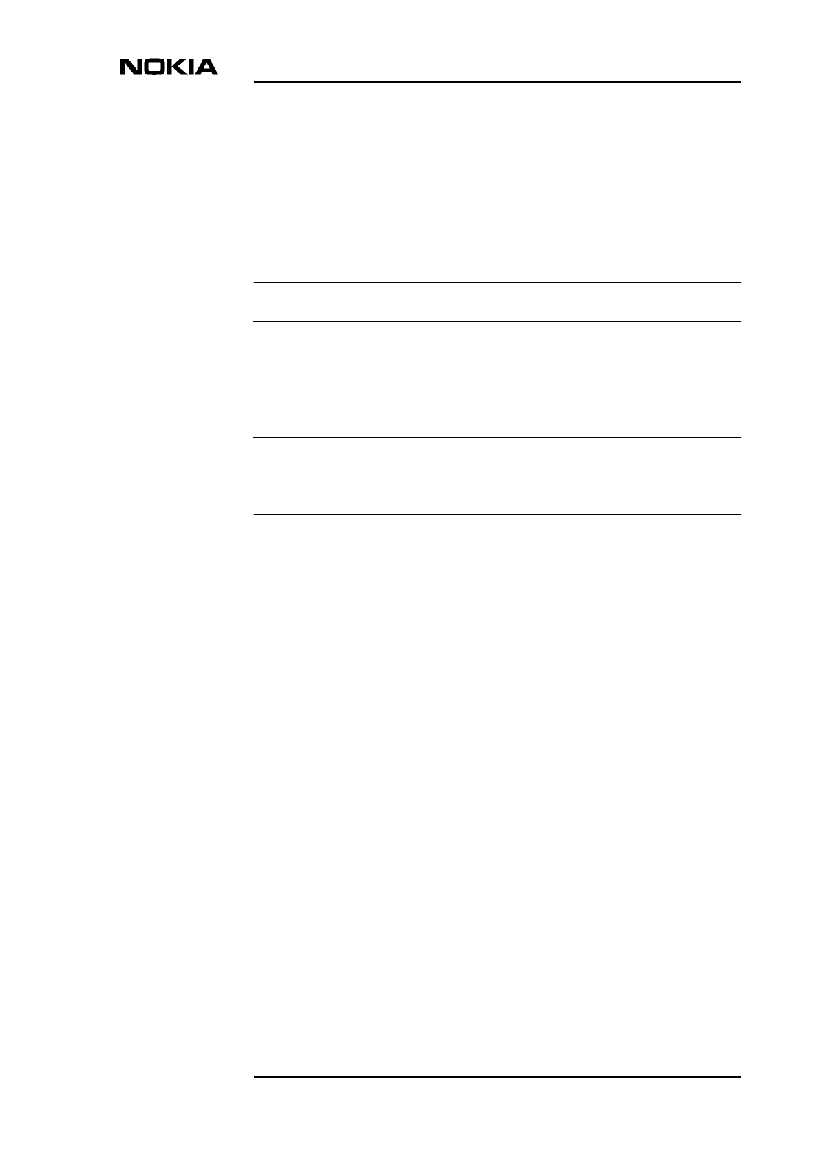
7.1.1 LIF settings for F(X)C E1/T1 transmission units
Define E1/T1 LIF settings as follows:
1. Select the tab for the line interface you want (LIF 1 - LIF 4).
If the transmission unit type is FC (no cross-connection capability), the dialogue
box has only one tab, LIF 1.
2. Tick the ‘Interface in Use’ option.
3. Select the interface mode from the list. If you select ‘T1 100 ohm’,
additional settings appear in the dialogue box. See Step 5.
4. Tick the ‘CRC in Use’ option if this is defined at the BSC.
5. If you selected the ‘T1 100 ohm’ interface mode, you need to define the
TS0 fixed bits. TS0 fixed bits from 1 to 3 are reserved for CRC and frame
locking. Bits 4 to 8 are used for alarms and data transfer in national
connections.
Commissioning
54 (78) © Nokia Corporation Draft DN999099
Nokia Proprietary and Confidential Issue 4-0 en
Note
6. If the type of the transmission unit is FXC E1/T1, check or modify the
settings for the other line interfaces as described in Steps 1 - 5.
7. Click OK to accept the changes.
Figure 23. LIF Settings with the FXC E1/T1 interface unit
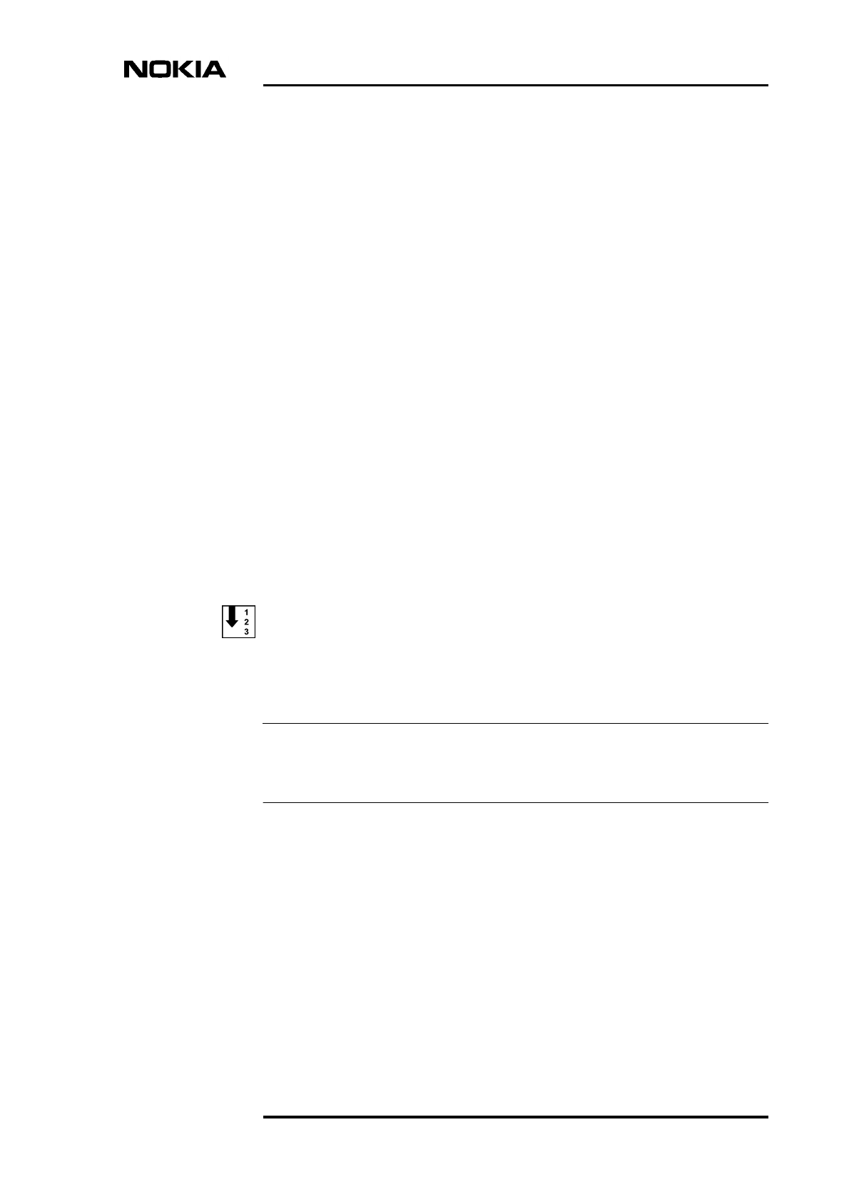
7.1.2 LIF settings for F(X)C RRI transmission units
Define RRI LIF settings as follows:
1. Select the tabbed page for the line interface you want (Flexbus 1, Flexbus
2, or Platform Interface).
If the transmission unit type is FC RRI (no cross-connection capability), the
dialogue box has only two tabbed pages: Flexbus 1 and Platform Interface.
2. Tick the ‘In Use’ option.
3. Select the ‘Capacity’ option for the interface (2, 4, 8, or 16 x 2 MB).
Line interface and synchronization settings
DN999099 © Nokia Corporation Draft 55 (78)
Issue 4-0 en Nokia Proprietary and Confidential
4. Select the ‘Power’ option as ‘On’.
5. If the transmission unit type is FXC RRI, check or modify the settings for
the other line interfaces, as described in steps 1 - 4.
6. Click OK to accept the changes.
Figure 24. LIF settings with the FXC RRI unit
7.2 Synchronization settings
The contents of the Synchronization dialogue box depends on the type of
transmission unit, F(X)C E1/T1 or RRI. There is no Synchronization dialogue
box for the FC RRI unit.
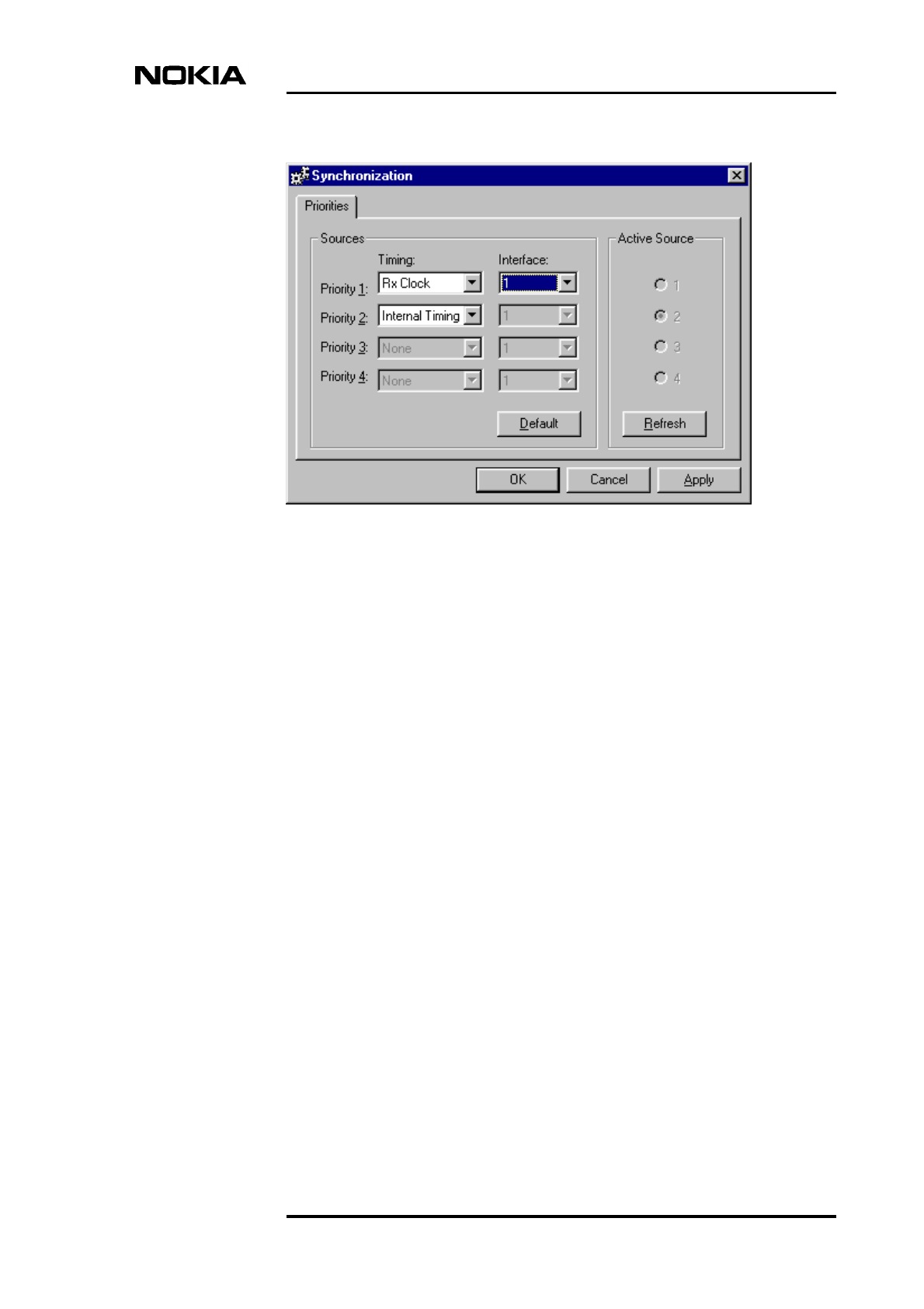
7.2.1 Synchronization settings for F(X)C E1/T1 transmission units
Define the E1/T1 synchronization settings as follows:
1. Select the ‘Timing’ option for priority 1 as ‘Rx Clock’ and select the
interface that is used for synchronization (uplink direction).
If the transmission unit in the BTS configuration is F(X)C E1/T1, you can
define settings for other priorities.
Commissioning
56 (78) © Nokia Corporation Draft DN999099
Nokia Proprietary and Confidential Issue 4-0 en
Note
2. Click OK to accept the changes.
Figure 25. Synchronization settings with FXC E1/T1 unit
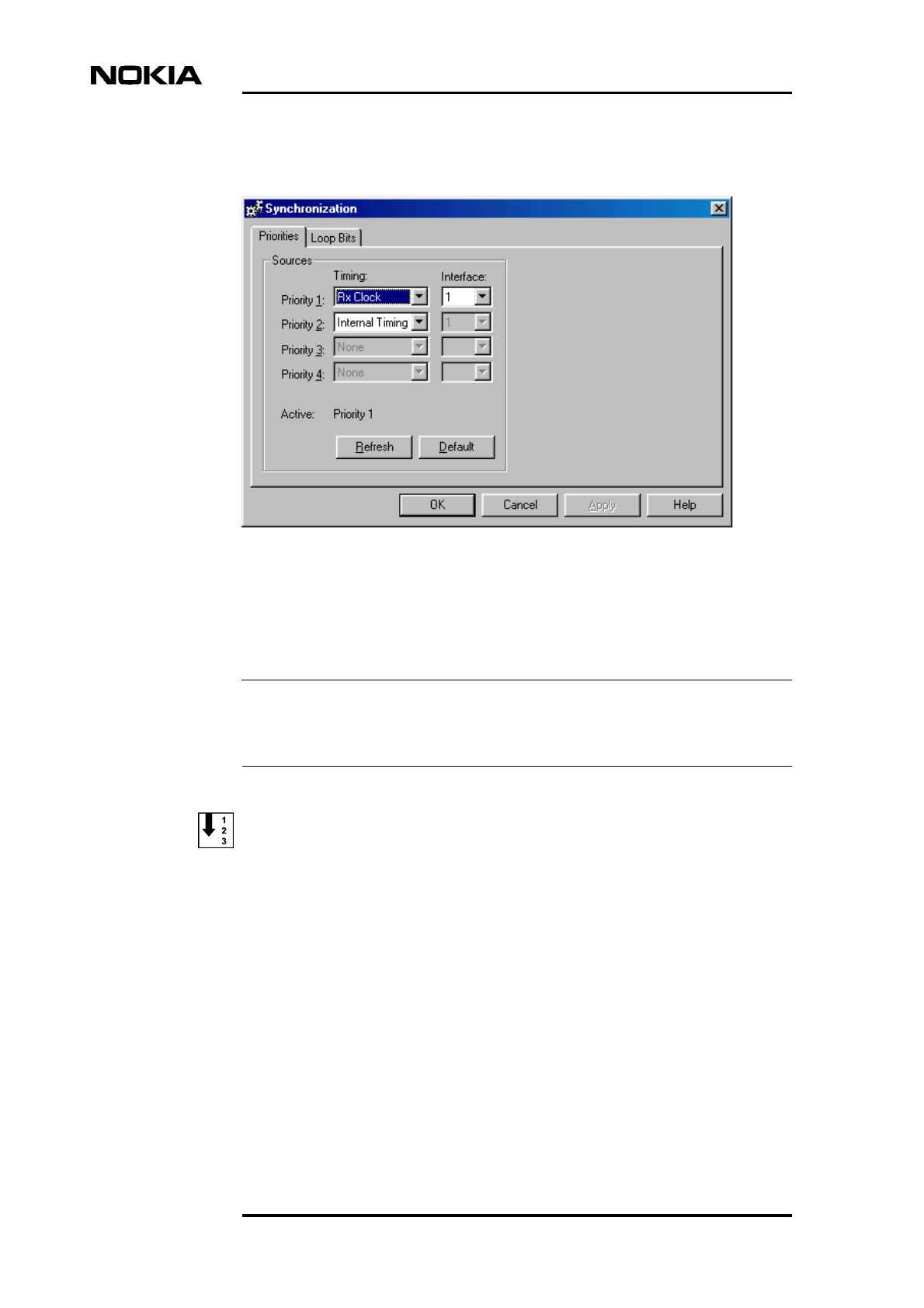
7.2.2 Synchronization settings for FXC RRI transmission units
There is no Synchronization dialogue box for the FC RRI unit, because the only
available timing option is Rx Clock.
Define RRI synchronization settings as follows:
1. Select the ‘Timing’ option for priority 1 as ‘Rx Clock’ and select the
interface number.
If necessary, define settings for the other priorities in the same way.
2. To see which timing source is currently active, click the REFRESH button.
3. Click OK to accept the changes.
Line interface and synchronization settings
DN999099 © Nokia Corporation Draft 57 (78)
Issue 4-0 en Nokia Proprietary and Confidential
Figure 26. Synchronization settings with FXC RRI unit

Commissioning
58 (78) © Nokia Corporation Draft DN999099
Nokia Proprietary and Confidential Issue 4-0 en
Radio Wizard
DN999099 © Nokia Corporation Draft 59 (78)
Issue 4-0 en Nokia Proprietary and Confidential
Note
Note
8Radio Wizard
When you click the RADIO HOP(S) button on the Radio Link Settings page in the
BTS Commissioning Wizard, the Radio Wizard is launched from the Nokia
MetroSite RRI Manager application. The Radio Wizard guides you through a
series of tasks for defining Flexbus and outdoor unit settings.
For more information on the commissioning and maintenance of radio units, see
the Nokia MetroHopperTM and FlexiHopperTM user manuals.
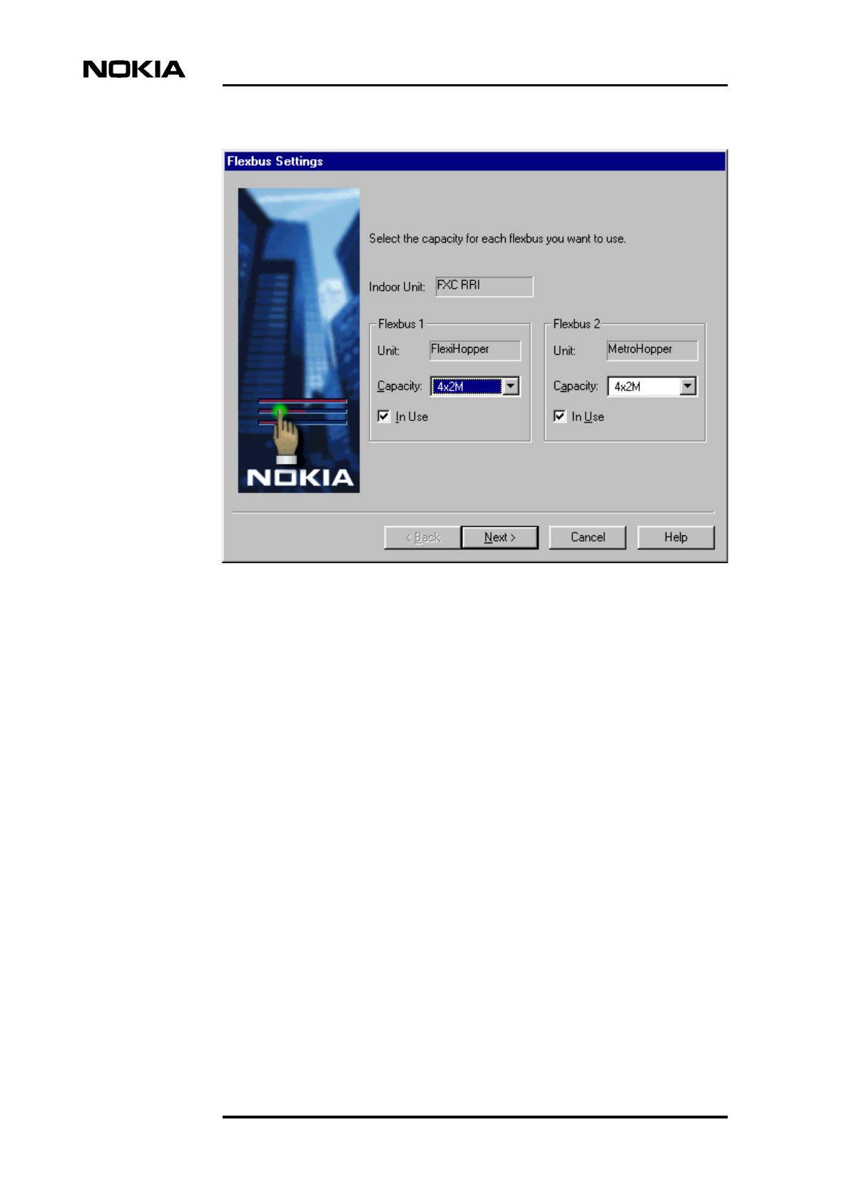
Commission radios as follows:
1. The Flexbus Settings page appears after you click the RADIO HOP(S)
button in the BTS Commissioning Wizard. The page displays the types of
indoor and outdoor units connected to each Flexbus.
Select the capacity for each outdoor unit from the ‘Capacity’ list and tick
the ‘In Use’ option for each Flexbus you want to use. At least one outdoor
unit must exist and be enabled (‘In Use’), before you can continue to the
next Wizard page.
With the Nokia MetroHopper outdoor unit, the capacity is fixed at 4 x 2 Mbit/s.
If the transmission unit type is FC RRI, the page displays only Flexbus 1 settings.
Click NEXT to continue.
Commissioning
60 (78) © Nokia Corporation Draft DN999099
Nokia Proprietary and Confidential Issue 4-0 en
Figure 27. Flexbus settings with FXC RRI card
2. The Flexbus 1 - FlexiHopper Settings page appears on the screen. The
options on the page depend on the outdoor unit connected to the interface.
The settings for the FlexiHopper outdoor unit are presented in Figure 28.

Commissioning
62 (78) © Nokia Corporation Draft DN999099
Nokia Proprietary and Confidential Issue 4-0 en
Note
Note
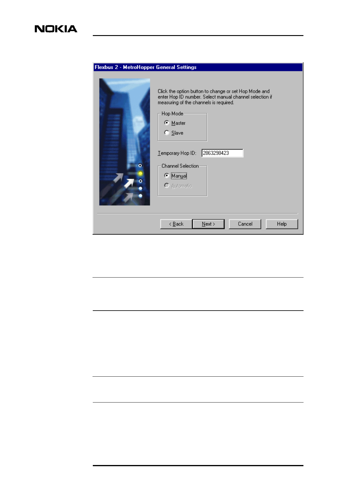
Figure 29. Flexbus 2 settings for the MetroHopper outdoor unit
The Temporary Hop ID on the MetroHopper General Settings page must be the
same for both the master and slave terminal.
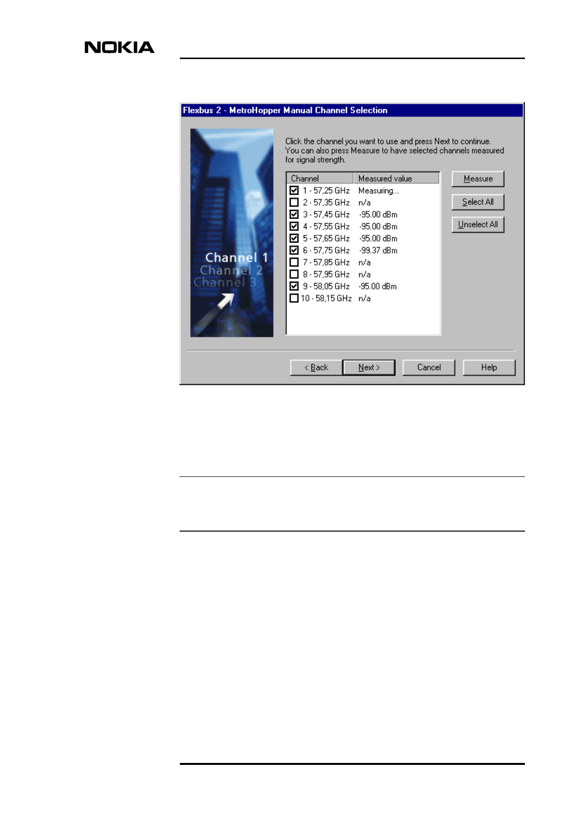
Select ‘Manual’ under ‘Channel Selection’ on the Flexbus 2 -
MetroHopper General Settings page. When you click NEXT, the Flexbus
2 - MetroHopper Manual Channel Selection page appears (see Figure 30).
Select one channel to be used. You can also click MEASURE to measure
the signal strength of the selected channels and then select the best channel.
At least one channel must be selected, before you can continue to the next page.
Radio Wizard
DN999099 © Nokia Corporation Draft 63 (78)
Issue 4-0 en Nokia Proprietary and Confidential
Note
Figure 30. MetroHopper manual channel selection
Click NEXT to continue.
If the transmission unit type is FC RRI, there are no Flexbus 2 settings. Proceed
to Step 4.
3. If the transmission unit type is FXC RRI, define the Flexbus 2 settings for
the outdoor unit as described in Step 2.
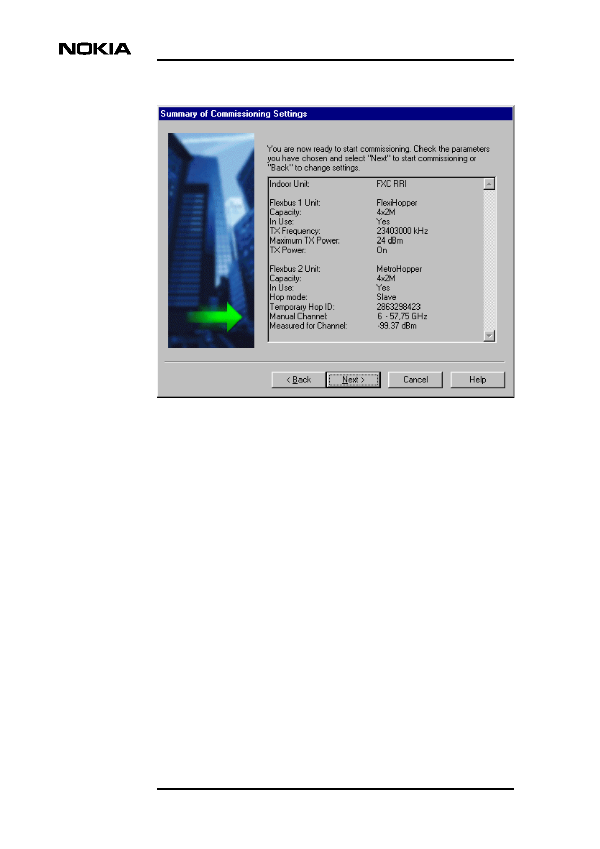
4. The Summary of Commissioning Settings page displays the settings you
have defined for commissioning the radio(s).
Commissioning
64 (78) © Nokia Corporation Draft DN999099
Nokia Proprietary and Confidential Issue 4-0 en
Figure 31. Summary of commissioning settings
Check that the settings are correct and click NEXT to start the actual
commissioning procedure.
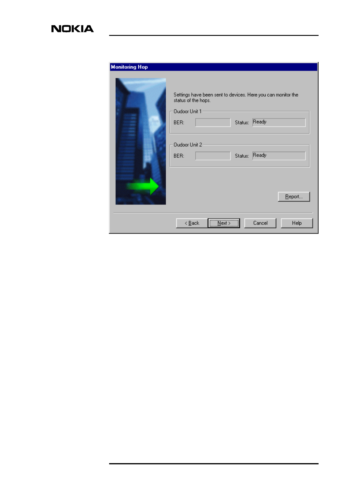
5. The Monitoring Hop page displays the status of the hops during and after
commissioning. The ‘Status’ is shown as ‘Ready’ if the commissioning
was successful. If the commissioning fails for some reason, the ‘Status’
field gives a short description of the failure (such as ‘No far end found’).
Commissioning
66 (78) © Nokia Corporation Draft DN999099
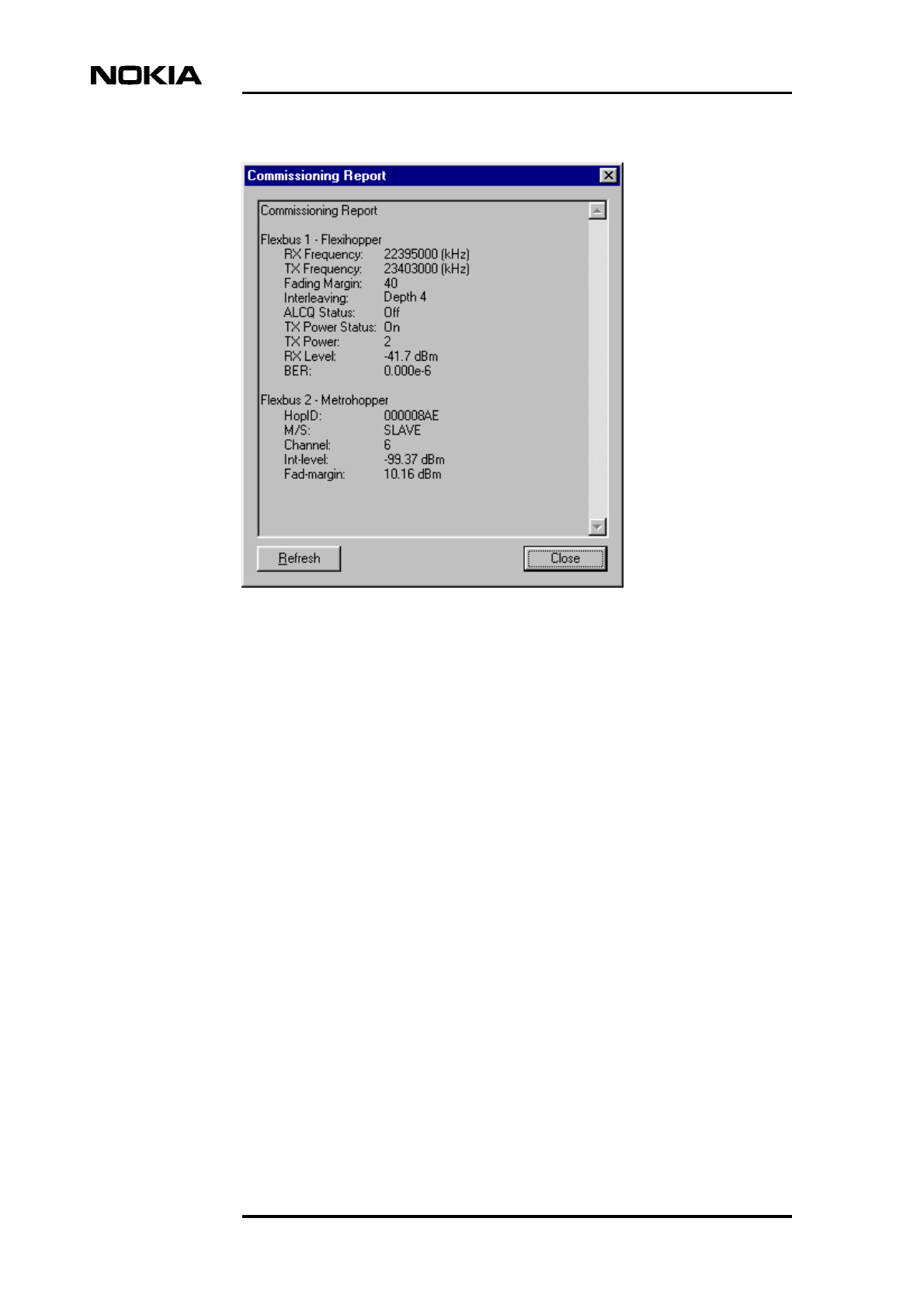
Nokia Proprietary and Confidential Issue 4-0 en
Figure 33. Commissioning report for outdoor units
Click NEXT on the Monitoring Hop page to return to the BTS
Commissioning Wizard.
Cross-connections
DN999099 © Nokia Corporation Draft 67 (78)
Issue 4-0 en Nokia Proprietary and Confidential
Note
Note
9Cross-connections
Cross-connections need to be created for routing transmission capacity to the
other BTSs in a chain or loop transmission topology.
Cross-connections are only supported with the FXC type transmission units.
The BTS has to be commissioned before creating the cross-connections.
9.1 Creating cross-connections
Cross-connections are created with the E1/T1 Manager (Transmission Unit
Manager) application in Nokia BTS Manager.
Cross-connections define how signals are routed from an FXC transmission unit
to another transmission unit. Cross-connections are created into inactive banks.
The cross-connections in the active banks are in use, whereas those in inactive
banks can be used for creating or editing cross-connections. The procedure below
describes how to create bi-directional cross-connections.
Creating bi-directional cross-connections:
1. Open E1/T1 Manager by selecting TRANSMISSION | OPEN on the BTS
Manager menu bar. The E1/T1 Manager is launched and the BTS Manager
session terminates.
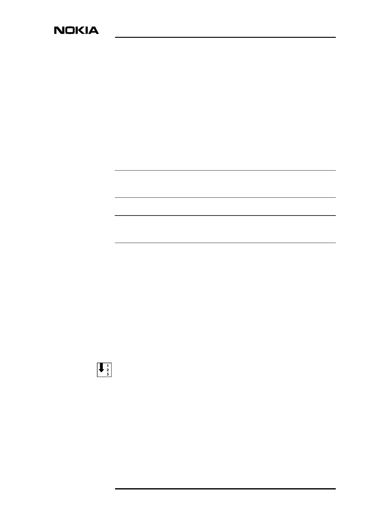
2. Select CONFIGURATION | CROSS-CONNECTIONS on the E1/T1
Manager menu bar. The Cross-connections window opens, as shown in
Figure 34.
Commissioning
68 (78) © Nokia Corporation Draft DN999099
Nokia Proprietary and Confidential Issue 4-0 en
Figure 34. Cross-connections window in E1/T1 Manager
3. Click on the ‘Inactive bank’ tab to open the inactive bank page.
4. Click the ‘Connections’ ADD button to open the Add Cross-Connection
Wizard - TX1/RX1 dialogue box.
5. Select the desired interface by clicking the interface symbol.
6. Define the following settings according to your cross-connection plan:
• Label (the name of the new cross-connection, maximum 80
characters).
• Cross-connection type; in this case the type is ‘bi-directional’.
• Granularity (with nx64k, set also its coefficient n).
• Cross-connection class.
• Timeout.

Cross-connections
DN999099 © Nokia Corporation Draft 69 (78)
Issue 4-0 en Nokia Proprietary and Confidential
7. Click the NEXT button in the wizard to open the TX2/RX2 dialogue box.
8. Select the next interface, such as Interface 2.
9. Define the settings for this second interface and click NEXT.
10. The Overview dialogue box will open. Depending on the type of cross-
connection, various fields will be enabled for defining the cross-connection
parameters according to your cross-connection plan. For more information
on the parameters, see the on-line Help in E1/T1 Manager.
Click FINISH.
11. The Add Cross-connection Wizard will close and you will return to the
Cross-connections window. The new cross-connection appears in the list
in the upper part of the window.
12. Activate the bank by clicking the ‘Banks’ ACTIVATE button. Click YES
when the E1/T1 manager asks you to confirm the operation.
13. Repeat Steps 1 - 12 for other types of cross-connections.
14. Quit the transmission unit manager by clicking the CLOSE button. Nokia
BTS Manager starts again automatically.
Editing a bank
You can start to edit existing settings in an inactive bank by double-clicking the
particular connection in the cross-connection list view in the Cross-connection
window or by selecting the connection and choosing the EDIT command on the
pop-up menu (which appears when you right-click the mouse).
If you have activated the bank, you need to copy the cross-connection information
to the inactive bank for editing because active banks cannot be edited. The COPY
command also is available in the pop-up menu.

Commissioning
70 (78) © Nokia Corporation Draft DN999099
Nokia Proprietary and Confidential Issue 4-0 en

Commissioning Report
DN999099 © Nokia Corporation Draft 71 (78)
Issue 4-0 en Nokia Proprietary and Confidential
10 Commissioning Report
At the end of the commissioning procedure, the BTS Commissioning Report is
saved as a file on the PC hard disk. See Figure 12 for an example of saving a
Commissioning Report at the end of the BTS Commissioning Wizard procedure.
The report is an ASCII text file that you can open and check with any word
processor software, such as Microsoft Notepad.
The BTS Commissioning Report provides the following information:
• Report title, date and time, user name
• Network time
• BTS logical configuration
• Telecom status
• BTS HW report
• BTS SW report
• EAC input test report
• EAC output test report
• TS allocation report
• TRX test report
• Abis test report
• BTS alarm test report
• External TREs

Commissioning
72 (78) © Nokia Corporation Draft DN999099
Nokia Proprietary and Confidential Issue 4-0 en

Troubleshooting and fault reporting
DN999099 © Nokia Corporation Draft 73 (78)
Issue 4-0 en Nokia Proprietary and Confidential
Note
11 Troubleshooting and fault reporting
In the case of a failure in the commissioning procedure, check if there is a
corresponding alarm in the Alarms window in Nokia BTS Manager (see the BTS
Alarm Descriptions document in the Nokia MetroSite EDGE Base Station SW
release binder). Also, you may check the cause of a failure from the
commissioning report.
The commissioning procedure may fail for the following reasons:
• The Abis cables are not properly connected (the transmission unit LED will
not show green).
• The pre-configuration failed at the BSC. For example, the BCF and TRX
objects were not created.
• PCM time-slot allocations are incorrect. The parameters at the BSC and on
the site are not the same. Run ‘Undo Commissioning’ and redo
commissioning with the correct parameters.
• The PCM port is not activated at the BSC.
• The transmission path is incorrectly configured. Check cross-connections.
• The CRC and/or interface mode settings for the E1/T1 card are incorrect.
In BTS Manager, choose LIF SETTINGS on the TRANSMISSION menu,
and check that the ‘CRC in Use’ and ‘Interface Mode’ settings are correct
for the interface.
Before starting to re-commission the BTS, first run the ‘Undo Commissioning’
procedure. If the Commissioning Wizard has stopped, click CANCEL to abort the
commissioning procedure.
Report all damages, failures or faults to Nokia using the Failure Report Form
provided by Customer Services (CS).

Commissioning
74 (78) © Nokia Corporation Draft DN999099
Nokia Proprietary and Confidential Issue 4-0 en
LMP connector description
DN999099 © Nokia Corporation Draft 75 (78)
Issue 4-0 en Nokia Proprietary and Confidential
Appendix A. LMP connector description
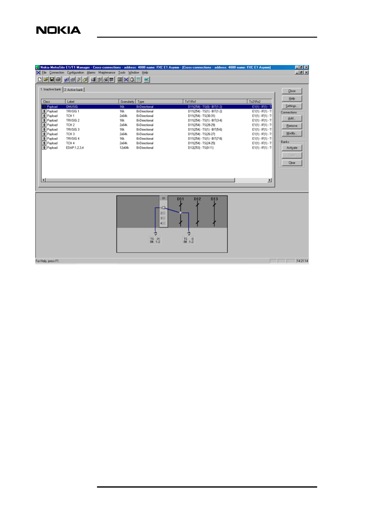
Figure 35 below describes the connectors and pin order of the LMP cable which
connects the Nokia BTS Manager PC to the BTS. The cable can be ordered from
Nokia.
Figure 35. LMP cable connectors
43
2
1
43
2
15
9876
= Hole
= Pin
1 nc
2 RD
3 TD
4 nc
5 GND
6 nc
7 nc
8 nc
9 nc
3 LMP out
2 LMP in
4 GND
2 nc GND = Ground
RD = Received data
TD = Transmitted data
nc = not connected
BQ on the BTS end
of cable
D9P (female) on the PC
end of cable

Commissioning
76 (78) © Nokia Corporation Draft DN999099
Nokia Proprietary and Confidential Issue 4-0 en

DN999099 ©Nokia Corporation Draft 77 (78)
Issue 4-0 en Nokia Proprietary and Confidential
Index
A
Abis connected 32
Abis not connected 33
allocating dynamic Abis for EDGE 48
allocating transmission capacity 42
allocating transmission capacity for chaining 46
B
bi-directional cross-connections 67
BTS Manager 21
C
commissioning 27
Commissioning Report 37
Commissioning Wizard 27
cross-connection, creating 67
D
Dynamic Abis 42
E
EAC inputs 34
EAC outputs 36
EDAP 42
EDGE transmission 48
EGPRS dynamic Abis pool 48
F
fault reporting, commissioning 73
H
Help, using 24
I
installing BTS Manager 21
installing Nokia BTS Manager 21
L
LIF settings 29,53
line interface settings 29,53
LMP cable 75
M
Manager software 21
N
Nokia BTS Manager 21
Nokia BTS Manager’s Wizard 27
O
OMUSIG 51
OMUSIG/TRXSIG1 51
on-line Help 24
R
radio links 31
Radio Wizard 59
S
signal types 51
Synchronization settings 30,55
T
TCHs 51
Traffic Manager 31,41
transmission capacity allocation 42
transmission capacity allocation for chaining 46
Transmission Parameters 29
troubleshooting, commissioning 73
TRXSIG 52
TRXSIG on TCHs 52
W
Wizard 27

Commissioning
78 (78) © Nokia Corporation Draft DN999099
Nokia Proprietary and Confidential Issue 4-0 en