Nokia Solutions and Networks WTPA-01 GSM 1900 Transceiver User Manual dn00187365x2x0xen
Nokia Solutions and Networks GSM 1900 Transceiver dn00187365x2x0xen
Contents
Field Upgrade

Nokia MetroSite EDGE Base Station
DN00187365 © Nokia Corporation Draft 1 (50)
Issue 2-0 en Nokia Proprietary and Confidential
Field Upgrade

Field Upgrade
2 (50) © Nokia Corporation Draft DN00187365
Nokia Proprietary and Confidential Issue 2-0 en
The information in this documentation is subject to change without notice and describes only
the product defined in the introduction of this documentation. This documentation is intended
for the use of Nokia's customers only for the purposes of the agreement under which the
documentation is submitted, and no part of it may be reproduced or transmitted in any form or
means without the prior written permission of Nokia. The documentation has been prepared to
be used by professional and properly trained personnel, and the customer assumes full
responsibility when using it. Nokia welcomes customer comments as part of the process of
continuous development and improvement of the documentation.
The information or statements given in this documentation concerning the suitability, capacity,
or performance of the mentioned hardware or software products cannot be considered binding
but shall be defined in the agreement made between Nokia and the customer. However, Nokia
has made all reasonable efforts to ensure that the instructions contained in the documentation
are adequate and free of material errors and omissions. Nokia will, if necessary, explain issues
which may not be covered by the documentation.
Nokia's liability for any errors in the documentation is limited to the documentary correction of
errors. NOKIA WILL NOT BE RESPONSIBLE IN ANY EVENT FOR ERRORS IN THIS
DOCUMENTATION OR FOR ANY DAMAGES, INCIDENTAL OR CONSEQUENTIAL
(INCLUDING MONETARY LOSSES), that might arise from the use of this documentation or
the information in it.
This documentation and the product it describes are considered protected by copyright
according to the applicable laws.
NOKIA logo is a registered trademark of Nokia Corporation.
Other product names mentioned in this documentation may be trademarks of their respective
companies, and they are mentioned for identification purposes only.
Copyright © Nokia Corporation 2002. All rights reserved.

DN00187365 © Nokia Corporation Draft 3 (50)
Issue 2-0 en Nokia Proprietary and Confidential
Hereby, Nokia Corporation, declares that this product is in compliance with the
essential requirements and other relevant provisions of Directive: 1999/5/EC.
The product is marked with the CE marking and Notified Body number according to the
Directive 1999/5/EC
FCC FCC §15.21 - Information to user - This product is used as an intentional radiated
equipment and any changes or modifications on the equipment without any approval
by Nokia could void the user's authority to operate the equipment.
FCC §15.105 - Information to user - This equipment has been tested and found to
comply with the limits for a Class B digital device, pursuant to part 15 of the FCC
Rules. These limits are designed to provide reasonable protection against harmful
interference in a residential installation. This equipment generates, uses and can
radiate radio frequency energy and, if not installed and used in accordance with the
instructions, may cause harmful interference to radio communications. However, there
is no guarantee that interference will not occur in a particular installation. If this
equipment does cause harmful interference to radio or television reception, which can
be determined by turning the equipment off and on, the user is encouraged to try to
correct the interference by one or more of the following measures:
• Reorient or relocate the receiving antenna.
• Increase the separation between the equipment and receiver.
• Connect the equipment into an outlet on a circuit different from that to which the
receiver is connected.
• Consult the dealer or an experienced radio/TV technician for help.
0523

Field Upgrade
4 (50) © Nokia Corporation Draft DN00187365
Nokia Proprietary and Confidential Issue 2-0 en

DN00187365 © Nokia Corporation Draft 5 (50)
Issue 2-0 en Nokia Proprietary and Confidential
Contents
Contents 5
List of tables 7
List of figures 8
1 Overview of field upgrade 9
1.1 GSM to GSM/EDGE upgrade 9
1.1.1 Working order for GSM/EDGE upgrade 9
1.1.2 Working order for 1W TRX power upgrade 10
1.2 Capacity upgrade by BTS chaining 11
1.2.1 Working order for a MetroSite EDGE BTS chaining upgrade 11
2 Preparing for upgrade 13
2.1 Power supply precautions 13
2.2 Checking warnings and cautions 14
2.3 Checking the upgrade deliveries 15
2.3.1 Parts required for a GSM/EDGE upgrade 15
2.3.2 Parts required for a BTS chaining upgrade 15
2.4 Checking the site for an upgrade 16
2.4.1 Checking environmental conditions on the site 16
2.5 Checking the installation equipment 17
2.6 Removing the BTS cover 17
2.7 ESD protection 18
3 Replacing the power supply unit 21
3.1 PSU removal 21
3.2 PSU installation 23
4 Replacing the cooling fan 25
4.1 Removing the VMFA cooling fan 25
4.2 Installing the HVMF high capacity cooling fan 28
5 Replacing or installing new TRX units 31
5.1 Upgrading by replacing TRXs 32
5.1.1 Removing TRX units 32
5.1.2 Installing TRX units 34
5.2 Upgrading capacity by adding TRXs 35
6 Chaining Nokia MetroSite EDGE BTSs 37
6.1 Setting up a chaining connection 39
7 Commissioning for upgrade 41
7.1 Commissioning the BTS for GSM/EDGE 42
7.2 Commissioning the BTS chain 42
8 Completing the upgrade 45

DN00187365 © Nokia Corporation Draft 7 (50)
Issue 2-0 en Nokia Proprietary and Confidential
List of tables
Table 1. Power supply rules during BTS upgrade or maintenance procedures 14
Table 2. Parts required for a GSM/EDGE upgrade on the Nokia MetroSite EDGE
Base Station 15
Table 3. Tools and other equipment required for a field upgrade 17
Table 4. PSU types used in MetroSite base stations 21

Field Upgrade
8 (50) © Nokia Corporation Draft DN00187365
Nokia Proprietary and Confidential Issue 2-0 en
List of figures
Figure 1. Electro-static sensitive device symbol 18
Figure 2. Connecting the antistatic wrist strap 19
Figure 3. Power supply unit 22
Figure 4. Removing the units 23
Figure 5. Sealing strip and cable entry block 26
Figure 6. VMFA cooling fan assembly mounting screws 27
Figure 7. HVMF cooling fan assembly and mounting screws 29
Figure 8. Cable entry block, cable allocations 29
Figure 9. TRX slot order 32
Figure 10. Example of blocking a TRX in Nokia BTS Manager 33
Figure 11. Nokia MetroSite EDGE Base Station 5W GSM/EDGE TRX unit 36
Figure 12. Chaining connection for three Nokia MetroSite EDGE base stations 39
Figure 13. Routing the cables and fitting the cable cover 46
Figure 14. Nokia MetroSite EDGE BTS cover and safety strap 47

Overview of field upgrade
DN00187365 © Nokia Corporation Draft 9 (50)
Issue 2-0 en Nokia Proprietary and Confidential
Note
1Overview of field upgrade
This document provides instructions for upgrading an existing Nokia MetroSite
BTS installation. Field upgrades are done for the following reasons:
• Upgrade of TRXs from GSM to GSM/EDGE transmission (including
upgrade from 1W TRXs, if relevant).
• Upgrade of BTS capacity by chaining to include up to 12 TRXs.
This chapter describes the upgrade options in more detail and the working order
for the upgrade procedures.
1.1 GSM to GSM/EDGE upgrade
A GSM MetroSite BTS installation is upgraded to EDGE transmission by
replacing the GSM TRX units with 5W GSM/EDGE TRXs or by adding 5W
GSM/EDGE TRXs to any spare TRX slots in the BTS.
A software upgrade to CX 3.0 or later is also required for upgrade to EDGE. This
is done locally at the BTS during commissioning with Nokia BTS Manager.
With the 5W GSM/EDGE TRXs, MetroSite can operate with either GSM or
EDGE transmission.
If the MetroSite BTS still contains 1W TRXs, a higher capacity cooling fan and
a different power supply unit must also be fitted to the BTS when the TRXs are
upgraded to 5W GSM/EDGE TRXs.
1.1.1 Working order for GSM/EDGE upgrade
The procedures to be completed and the working order in which they are done are
presented below.

Field Upgrade
10 (50) © Nokia Corporation Draft DN00187365
Nokia Proprietary and Confidential Issue 2-0 en
Upgrading TRXs to GSM/EDGE
1. Read the information in Chapter 2 of this document, Preparing for
upgrade. This chapter contains essential information about when to power
down the BTS.
2. Check the type of TRX units currently installed to confirm that they are 5W
TRXs. For 1W TRX installations, see Section 1.1.2 this document.
3. Replace the existing TRX units with 5W GSM/EDGE TRXs, as described
in Chapter 5.1 of this document, Upgrading by replacing TRXs.
OR
Install new 5W GSM/EDGE TRXs to any spare TRX slots in the BTS, as
described in Chapter 5.2 of this document, Upgrading by adding TRXs.
4. Follow the procedures for Commissioning for upgrade in Chapter 7 of this
document.
5. Follow the procedures for Completing the upgrade in Chapter 8 of this
document.
1.1.2 Working order for 1W TRX power upgrade
The procedures to be completed and the working order in which they are done are
presented below.
Upgrading TRXs from 1W to 5W
1. Read the information in Chapter 2 of this document, Preparing for
upgrade. This chapter contains essential information about when to power
down the BTS.
2. Follow the procedures for Replacing the power supply unit in Chapter 3 of
this document.
3. Replace the existing TRX units with GSM/EDGE TRXs, as described in
Chapter 5 of this document, Replacing or adding new TRX units.
4. Follow the procedures for Replacing the fan unit in Chapter 4 of this
document.

Overview of field upgrade
DN00187365 © Nokia Corporation Draft 11 (50)
Issue 2-0 en Nokia Proprietary and Confidential
Note
5. Follow the procedures for Commissioning for upgrade in Chapter 7 of this
document.
6. Follow the procedures for Completing the upgrade in Chapter 8 of this
document.
1.2 Capacity upgrade by BTS chaining
The capacity of a Nokia MetroSite BTS installation can be upgraded by
connecting one or two slave BTSs to the master BTS with chaining cables via the
interface units. Up to 12 TRXs can be connected and set up as one BCF unit. Only
the master BTS needs a transmission unit.
All BTS cabinets in a chain must be upgraded to the GSM/EDGE standard.
1.2.1 Working order for a MetroSite EDGE BTS chaining upgrade
The procedures to be completed and the working order in which they are done are
presented below.
Chaining MetroSite BTSs
1. Read the information in Chapter 2 of this document, Preparing for
upgrade. This chapter contains essential information about when to power
down the BTS.
2. Follow the procedures for Chaining Nokia MetroSite EDGE BTSs in
Chapter 6 of this document.
3. Follow the procedures for Commissioning the BTS chain in Chapter 7.2 of
this document.
4. Follow the procedures for Completing the upgrade in Chapter 8 of this
document.

Field Upgrade
12 (50) © Nokia Corporation Draft DN00187365
Nokia Proprietary and Confidential Issue 2-0 en

Preparing for upgrade
DN00187365 © Nokia Corporation Draft 13 (50)
Issue 2-0 en Nokia Proprietary and Confidential
WARNING
WARNING
Note
2Preparing for upgrade
Before starting any upgrade procedures, the procedures and precautions presented
in this chapter should be read and implemented as required.
Some of the upgrade procedures require the BTS to be powered down. Read
Section 2.1, Power supply precautions, in this chapter before beginning the
upgrade.
2.1 Power supply precautions
Potentially lethal voltages!
The BTS power must be switched OFF at the main disconnect device or
circuit breaker before starting maintenance work which involves the risk of
electric shocks.
Prevent injury to personnel or damage to the BTS equipment by following the
power supply rules for maintenance and upgrade procedures presented in Table .
The switch on the power supply unit (PSU) of the BTS has two positions: ON and
Stand-by.

Field Upgrade
14 (50) © Nokia Corporation Draft DN00187365
Nokia Proprietary and Confidential Issue 2-0 en
2.2 Checking warnings and cautions
The warnings and cautions applicable to the MetroSite BTSs are detailed in Nokia
MetroSite EDGE Base Station: Warnings and Cautions. Read these before
beginning a field upgrade.
Table 1. Power supply rules during BTS upgrade or maintenance
procedures
BTS upgrade or maintenance
procedure Power supply rule for BTS
Replacing a power supply unit or PSU
cable
• Power OFF at main disconnect
device
• PSU switch to Stand-by
Replacing a grounding connection • Power OFF at main disconnect
device
• PSU switch to Stand-by
Disconnecting or connecting antenna or
diversity cables on a TRX
PSU can be switched to ON but TRX
must be blocked
Replacing a TRX PSU can be switched ON but TRX must
be blocked
Disconnecting or connecting
transmission cables
PSU can be switched ON but TRX must
be blocked
Replacing a transmission unit PSU switch to Stand-by
Connecting or disconnecting cables to
the interface unit (VIFA)
PSU switch to Stand-by is advised
Connecting cables to the interface unit
for BTS chaining
PSU switch to Stand-by
Replacing an interface unit PSU switch to Stand-by
Replacing a fan unit • Power OFF at main disconnect
device
• PSU switch to Stand-by

Preparing for upgrade
DN00187365 © Nokia Corporation Draft 15 (50)
Issue 2-0 en Nokia Proprietary and Confidential
2.3 Checking the upgrade deliveries
Check that the items delivered for the upgrade match the items required in your
upgrade/installation plan. Check the condition of the delivered items to confirm
that they are not damaged.
2.3.1 Parts required for a GSM/EDGE upgrade
Refer to Table 2 for details of the parts required for a GSM/EDGE upgrade.
2.3.2 Parts required for a BTS chaining upgrade
The following parts are required for a BTS chaining upgrade. The number of
items depends on whether there will be one or two slave cabinets in the chain.
Table 2. Parts required for a GSM/EDGE upgrade on the Nokia MetroSite
EDGE Base Station
Upgrade type Parts required
5W GSM to 5W GSM/EDGE upgrade • 5W GSM/EDGE TRX units
• Nokia SiteWizard with CX 3.0
software and Nokia BTS Manager
3.0 or later.
1W GSM to 5W GSM/EDGE upgrade • 5W GSM/EDGE TRX units
• Nokia SiteWizard with CX 3.0
software and Nokia BTS Manager
3.0 or later.
• HVSA, HVSB, HVSC, or HVSD type
power supply unit (see Chapter 3 for
specifications)
• HVMF type high capacity fan unit
• HVCU type BTS cover, for use with
high capacity fan

Field Upgrade
16 (50) © Nokia Corporation Draft DN00187365
Nokia Proprietary and Confidential Issue 2-0 en
Note
• One or two Nokia MetroSite EDGE BTS base stations with GSM/EDGE
TRXs but without transmission units (depending on the number of slave
BTS cabinets planned).
The BTS cabinets will need to be installed as described in the document, Nokia
MetroSite EDGE Base Station: Installation. The parts required for BTS
installation are listed in that document.
• One or two Nokia MetroSite BTS extension cable kits (depending on the
number of slave BTS cabinets planned). The kits contain a cable and a
termination connector. There are three different lengths of extension cable,
as follows:
• extension cable kit, 3 metres (part 467614A)
• long extension cable kit, 5 metres (part 469585A)
• short extension cable kit, 1 metre (part 469584A)
• Nokia SiteWizard with CX 3.0 software or later, and including Nokia BTS
Manager 3.0 or later.
2.4 Checking the site for an upgrade
Before beginning the upgrade, the site should be checked by the site supervisor.
The site should be checked against a site preparation checklist and confirmed as
correct according to the site drawings and plans.
The BTS site should be readily prepared according to the specifications given in
Nokia MetroSite EDGE Base Station: Requirements for Installation and
Operation. In the case of a BTS chaining upgrade, the extra BTS cabinets should
be already installed and checked.
If the site does not meet the requirements in the checklist, complete the site
deficiency reports and report to the Installation Manager / Site Manager before
continuing with the upgrade.
2.4.1 Checking environmental conditions on the site
Check the site conditions before starting the upgrade procedures. In the case of
precipitation (rain, snow or sleet), the site must be weather-guarded during the
upgrading procedure to prevent damage to the units when the BTS cover is
removed. Note the following:

Preparing for upgrade
DN00187365 © Nokia Corporation Draft 17 (50)
Issue 2-0 en Nokia Proprietary and Confidential
Note
• Rain or snow must not be allowed to fall on the internal surfaces of the
equipment.
• The cover must not be removed during conditions where dust can be blown
into the cabinet.
2.5 Checking the installation equipment
Table 3 presents a list of the tools and other equipment required for upgrading a
Nokia MetroSite BTS.
2.6 Removing the BTS cover
Before removing the cover of the BTS, refer to the information on power supply
precautions and environmental conditions on the site, presented earlier in this
chapter.
Removing the cover issues an alarm to the BSC. Make sure that the BSC/NMS
personnel is notified before removing the cover.
Table 3. Tools and other equipment required for a field upgrade
Part Notes
Laptop PC The PC should be compatible with Nokia
SiteWizard software version 3.0.
LMP cable For connecting BTS Manager software
to the BTS via the LMP port on the
interface unit
Torque driver with 60 mm (2.4 in) shaft
and:
• T10 and T25 Torx bits
• 4 mm Allen bit
Required for:
• Unit retaining screws
• Cable entry block screws
Torque key For attaching diversity cables
Cable ties and side cutting pliers For securing cable routing out of the BTS
ESD wrist strap To prevent electro-static discharge
damage

Field Upgrade
18 (50) © Nokia Corporation Draft DN00187365
Nokia Proprietary and Confidential Issue 2-0 en
Caution
Removing the BTS cover
1. Unlock the cabinet lock at the bottom of the BTS.
2. Remove the cover by sliding it upwards to disengage the hooks at the side
of the cover from the locking guides on the BTS chassis.
3. When the cover is free, pull it away from the cabinet and hang it on the
hook at the top left side of the chassis.
You can also remove the cover completely to place it on the floor. Remove
the safety strap before pulling the cover away (see Figure 14).
2.7 ESD protection
Some units in the MetroSite BTS contain electro-static sensitive devices. The
BTS is labelled with an electro-static sensitive device symbol as shown in Figure
1.
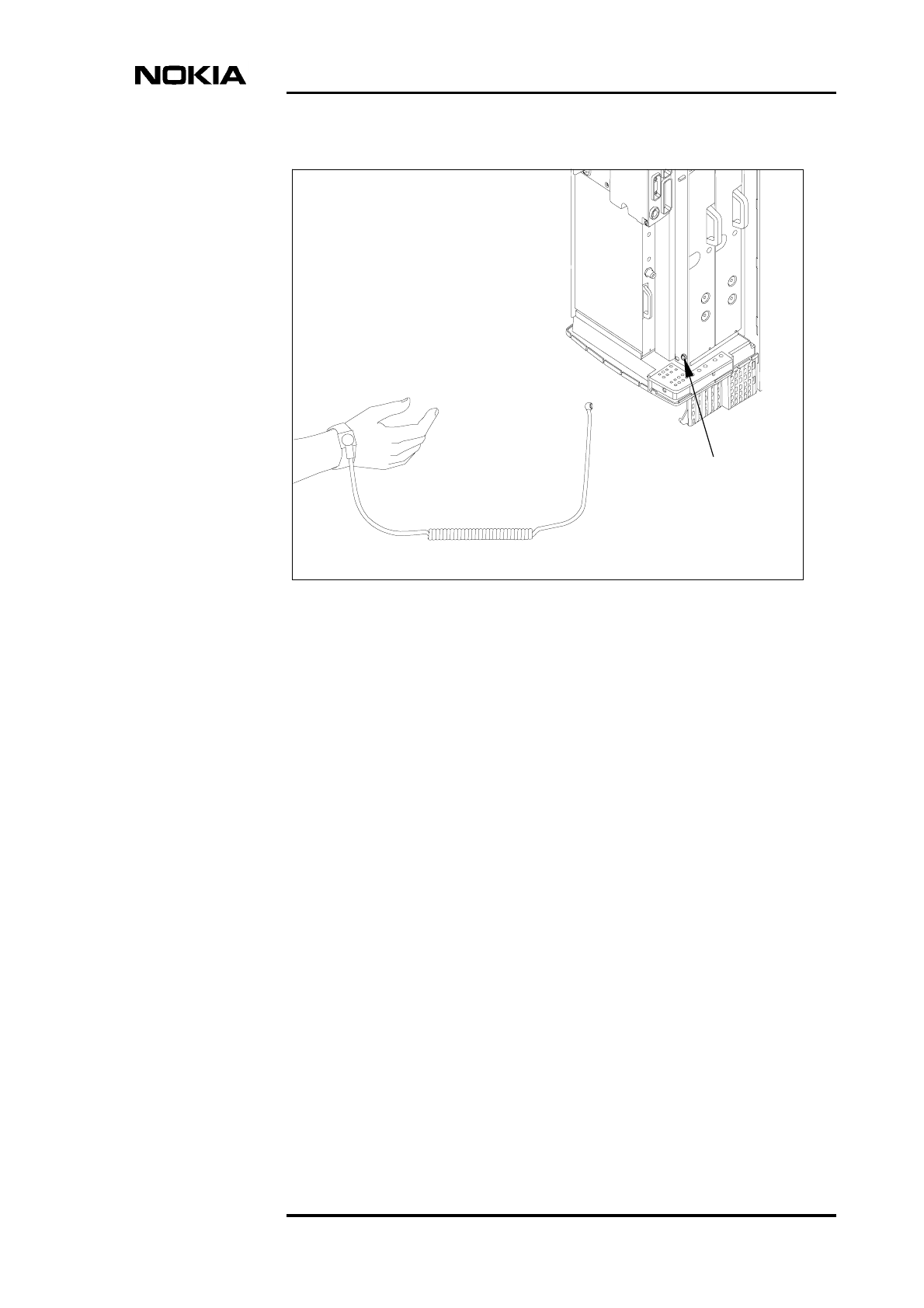
Always use an anti-static wrist strap connected to the cabinet ESD stud, whenever
handling electro-static sensitive units. The wrist strap and connection stud is
shown in Figure 2.
Figure 1. Electro-static sensitive device symbol
Preparing for upgrade
DN00187365 © Nokia Corporation Draft 19 (50)
Issue 2-0 en Nokia Proprietary and Confidential
Figure 2. Connecting the antistatic wrist strap
ESD stud
to ESD stud
Wrist strap

Field Upgrade
20 (50) © Nokia Corporation Draft DN00187365
Nokia Proprietary and Confidential Issue 2-0 en

Replacing the power supply unit
DN00187365 © Nokia Corporation Draft 21 (50)
Issue 2-0 en Nokia Proprietary and Confidential
Note
WARNING
3Replacing the power supply unit
The power supply unit (PSU) must be replaced only if the MetroSite BTS
installation is being upgraded from a 1W TRX configuration. See Table 4 for the
correct type of PSU replacements for a 5W TRX installation.
The PSU does not need replacing for 5W GSM to 5W GSM/EDGE field
upgrades.
3.1 PSU removal
Make sure that the power is turned OFF at the main disconnect device before
working on the PSU.
Table 4. PSU types used in MetroSite base stations
Input voltage 1W TRX BTS
installations
5W TRX BTS
installations
AC 230 V VSAA HVSA
AC 110 V VSAB HVSB
DC +24 V - HVSC
DC -48 V VSDA HVSD
Field Upgrade
22 (50) © Nokia Corporation Draft DN00187365
Nokia Proprietary and Confidential Issue 2-0 en
Removing the PSU
1. Turn the PSU power switch to Stand-by and turn the power OFF at the
BTS’s main power disconnect device.
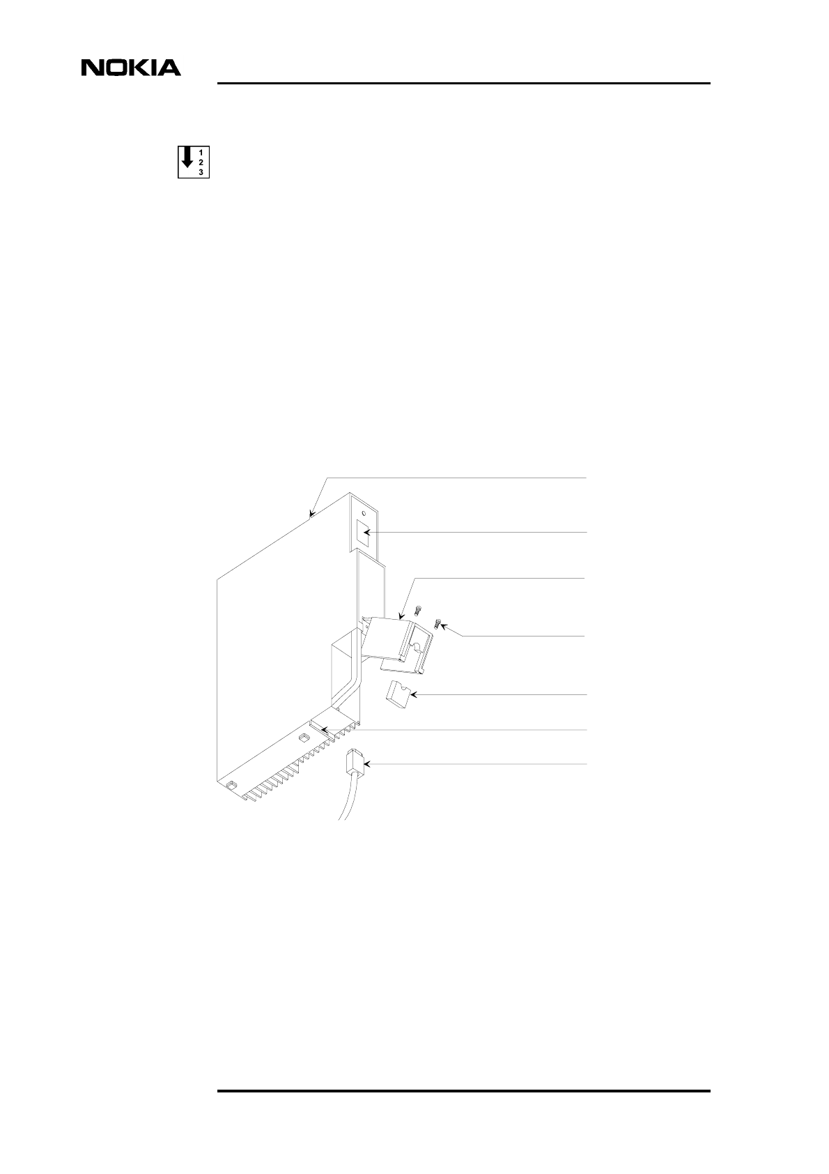
2. Open the power connector cover on the PSU by removing the retaining
screws with a T10 Torx driver (see Figure 3).
3. Unplug the power supply cable from the PSU.
4. Loosen the unit's upper and lower retaining screws on the mounting
brackets using a T10 Torx driver.
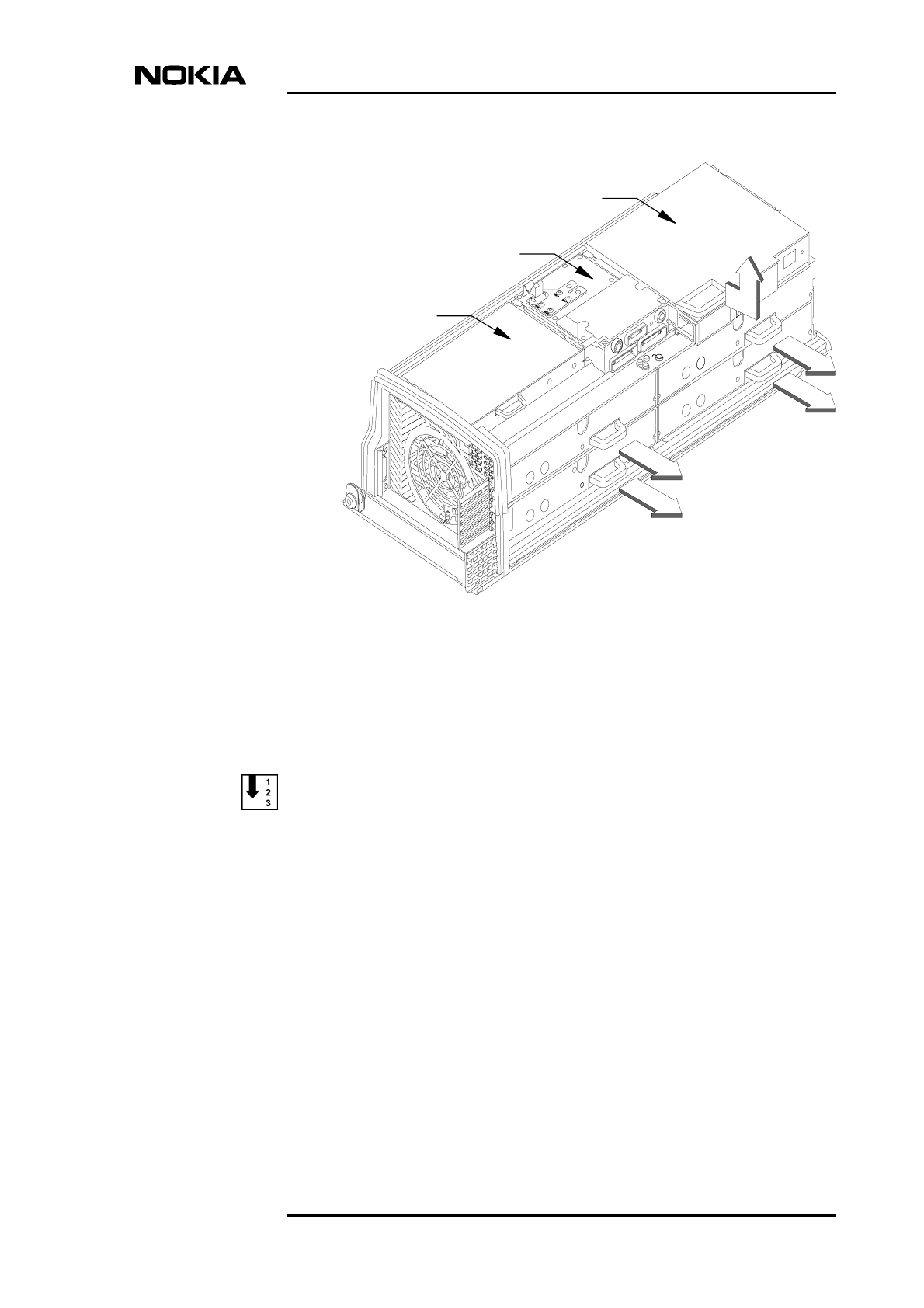
5. Slide the PSU unit out until it comes to a stop, then tilt the unit from the top
and remove it (see Figure 4).
Figure 3. Power supply unit
Upper mounting bracket
Main power switch
Power connector cover
Power cable seal
Power cable
Lower mounting bracket
Retaining screws
Replacing the power supply unit
DN00187365 © Nokia Corporation Draft 23 (50)
Issue 2-0 en Nokia Proprietary and Confidential
Figure 4. Removing the units
3.2 PSU installation
Installing the new PSU
1. Slide the PSU into the appropriate slot. See Figure 4.
2. Place the PSU into the bottom runner then push the top of the unit forward
into the clearance slots provided in the top runners.
3. Press the unit carefully into the connector on the backplane. Do not use
excessive force!
4. Tighten the two PSU mounting screws on the upper and lower mounting
brackets using a T10 Torx torque driver. Tighten to 1.5 Nm (1.1 lb ft).
5. Loosen the two T10 Torx retaining screws on the connector cover and open
the cover. See Figure 3.
Power supply unit
Interface unit
Transmission unit
Transceiver units

Field Upgrade
24 (50) © Nokia Corporation Draft DN00187365
Nokia Proprietary and Confidential Issue 2-0 en
6. Plug the power supply cable connector into the PSU power input socket.
7. Fit the power cable seal into the power connector cover. Close the cover
and tighten the retaining screws.
8. Turn the power ON at the BTS’s main power disconnect device and then
turn the PSU switch to the ON position.

Replacing the cooling fan
DN00187365 © Nokia Corporation Draft 25 (50)
Issue 2-0 en Nokia Proprietary and Confidential
Note
WARNING
4Replacing the cooling fan
The cooling fan assembly must be replaced only if the MetroSite BTS installation
is being upgraded from a 1W TRX configuration. The VMFA fan type fan must
be replaced by an HVMF type, high capacity cooling fan.
The BTS cover also needs replacing if the cooling fan is upgraded. The upgraded
version of the BTS cover (HVCU or WCUA) allows for the better ventilation
provided by the high power cooling fan.
The cooling fan does not need replacing for 5W GSM to 5W GSM/EDGE field
upgrades.
The cooling fan assembly is located on the bottom of the BTS cabinet. For
upgrade, the complete fan assembly is removed and replaced with the HVMF fan
upgrade kit, which includes the HVMF fan and complete fan assembly.
4.1 Removing the VMFA cooling fan
Make sure that the power is turned OFF at the main disconnect device before
working on the fan unit.
Complete the following procedures to remove the fan assembly.
Removing the cable entry block
1. Unclip and slide the cable cover towards you (see Figure 13).
Field Upgrade
26 (50) © Nokia Corporation Draft DN00187365
Nokia Proprietary and Confidential Issue 2-0 en
Note
2. Disengage and remove the cable cover support plate.
3. Remove all connecting cables to the units.
All connecting cables must be removed in order to replace the cooling fan outer
sealing gasket.
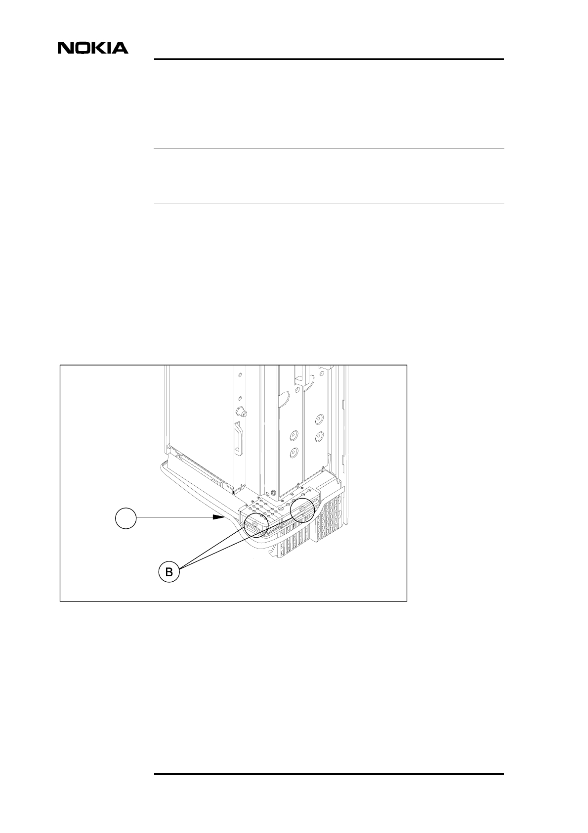
4. Detach the outer sealing gasket at the point where it covers the cable entry
block, see (A) in Figure 5.
5. Remove the two 4 mm (0.157 in) Allen screws on the cable entry block.
See (B) in Figure 5.
6. Open the cable entry block at the point where the cables are routed. See
Figure 8.
7. Disengage the cables from the cable entry block.
Figure 5. Sealing strip and cable entry block
A
Sealing strip
Allen screws
M6
Allen key 4 mm
Replacing the cooling fan
DN00187365 © Nokia Corporation Draft 27 (50)
Issue 2-0 en Nokia Proprietary and Confidential
Caution
Removing the VMFA fan assembly
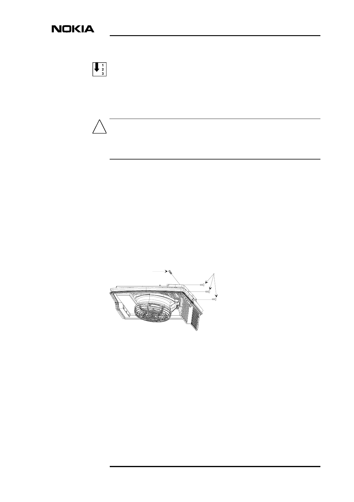
1. Remove and retain the fan assembly holding screws as follows (see Figure
6):
When the four fan assembly holding screws have been removed, the fan unit is
only supported in the cabinet by the backplane connector. Do not let go of the fan
assembly after releasing the screws.
a. Three T10 Torx screws on the right-hand side of the assembly.
b. One T25 Torx screw on the front of the assembly.
Hold the fan unit in place and proceed to the next step.
2. Loosen cooling fan assembly from the backplane connector by moving it
slightly backwards and forwards in the cabinet. The backplane connector
is on the left hand side of the cabinet.
Pull the fan assembly out of the connector and out from the bottom of the
cabinet.
Figure 6. VMFA cooling fan assembly mounting screws
T10
T25

Field Upgrade
28 (50) © Nokia Corporation Draft DN00187365
Nokia Proprietary and Confidential Issue 2-0 en
WARNING
4.2 Installing the HVMF high capacity cooling fan
Make sure that the power is turned OFF at the main disconnect device before
working on the fan unit.
Complete the following procedure to fit the HVMF fan assembly.
Install the HVMF fan assembly
1. Lift the new HVMF fan assembly to the bottom of the cabinet and align the
connector on the assembly with the backplane connector on the cabinet.
2. Push the assembly into the backplane connector. Do not use excessive
force!
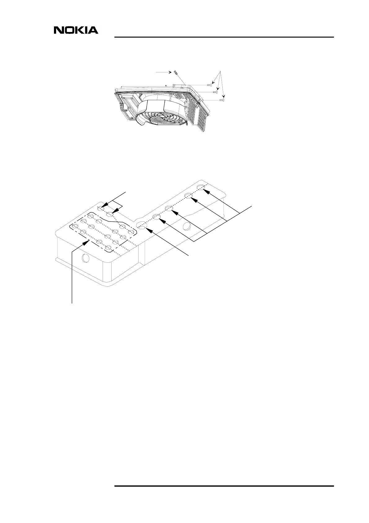
3. Refit the four fan assembly mounting screws in their respective slots (see
Figure 7):
a. 3 x T10 Torx on the right hand side of the assembly.
b. One T25 Torx at the front of the assembly.
4. Refit all the connecting cables:
a. Open the cable entry block and re-thread all cables through the outer
fan sealing gasket.
b. Reconnect all the cables.
c. Place the cables into their respective slots in the cable entry block
(see Figure 8).
5. Refit and tighten the two 4 mm (0.157 in) Allen screws on the cable entry
block (see Figure 5).
6. Refit the outer fan sealing gasket.
Replacing the cooling fan
DN00187365 © Nokia Corporation Draft 29 (50)
Issue 2-0 en Nokia Proprietary and Confidential
Figure 7. HVMF cooling fan assembly and mounting screws
Figure 8. Cable entry block, cable allocations
T10
T25
Antenna
cables
Power supply cable
Extension cables
- Grounding cable, 1 pc
- Transmission cables, max 8 pcs
- External alarms and controls

Field Upgrade
30 (50) © Nokia Corporation Draft DN00187365
Nokia Proprietary and Confidential Issue 2-0 en

Replacing or installing new TRX units
DN00187365 © Nokia Corporation Draft 31 (50)
Issue 2-0 en Nokia Proprietary and Confidential
Note
5Replacing or installing new TRX units
A MetroSite BTS can be upgraded to EDGE by replacing 1W or 5W GSM TRX
units with 5W GSM/EDGE units.
Additional TRXs can also be added to a single BTS (up to four TRXs) in order to
increase the BTS’s capacity or to add EDGE capability.
A 5W GSM/EDGE TRX can be commissioned to operate on GSM or
GSM/EDGE transmission.
It is possible for a BTS to contain a mixture of 5W GSM and 5W GSM/EDGE
TRX units.
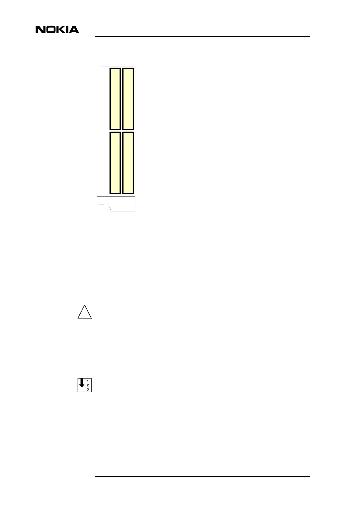
Figure 9 shows the slot order of TRX units in a MetroSite BTS. TRX 1 is always
the master TRX.
Field Upgrade
32 (50) © Nokia Corporation Draft DN00187365
Nokia Proprietary and Confidential Issue 2-0 en
Caution
Figure 9. TRX slot order
5.1 Upgrading by replacing TRXs
5.1.1 Removing TRX units
Refer to the power supply requirements in Table 1 before working on the TRX
units.
To make it easier to remove the antenna connectors, remove the TRX units in the
following order: TRX 3, 4, 1, 2 (see Figure 9).
Removing TRX units
1. Connect your Nokia BTS Manager PC to the LMP connector on the
interface unit.
T
R
X
3
T
R
X
4
T
R
X
1
T
R
X
2
Replacing or installing new TRX units
DN00187365 © Nokia Corporation Draft 33 (50)
Issue 2-0 en Nokia Proprietary and Confidential
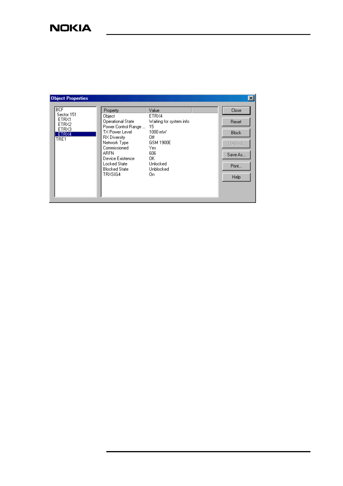
2. Block the TRX using Nokia BTS Manager (if the sector is not already
locked from the BSC). In the Supervision - Equipment View window, right
click on the TRX image and select the BLOCK button in the Object
Properties dialogue window (see Figure 10).
Figure 10. Example of blocking a TRX in Nokia BTS Manager
3. Make a note of the TRX cabling.
4. Disconnect the antenna and diversity cables from the TRX units to be
removed.
5. Loosen the units’ two retaining screws using a T10 Torx screwdriver.
6. Slide each TRX unit outwards to disengage it from the backplane
connector and then pull the unit upwards to remove it (see Figure 4). Use
the handle on the front of the TRX for pulling the unit.

Field Upgrade
34 (50) © Nokia Corporation Draft DN00187365
Nokia Proprietary and Confidential Issue 2-0 en
Note
5.1.2 Installing TRX units
In order to reach and tighten the antenna connectors with a torque spanner, it is
necessary to install the TRX units in the following order: TRX 4, 3, 2, 1 (see
Figure 9). The master TRX is located in slot 1.
If you are replacing a master TRX in a single TRX installation or increasing the
number of TRXs, refer to Nokia MetroSite EDGE Base Station: Maintenance for
more detailed information.
Installing TRX units
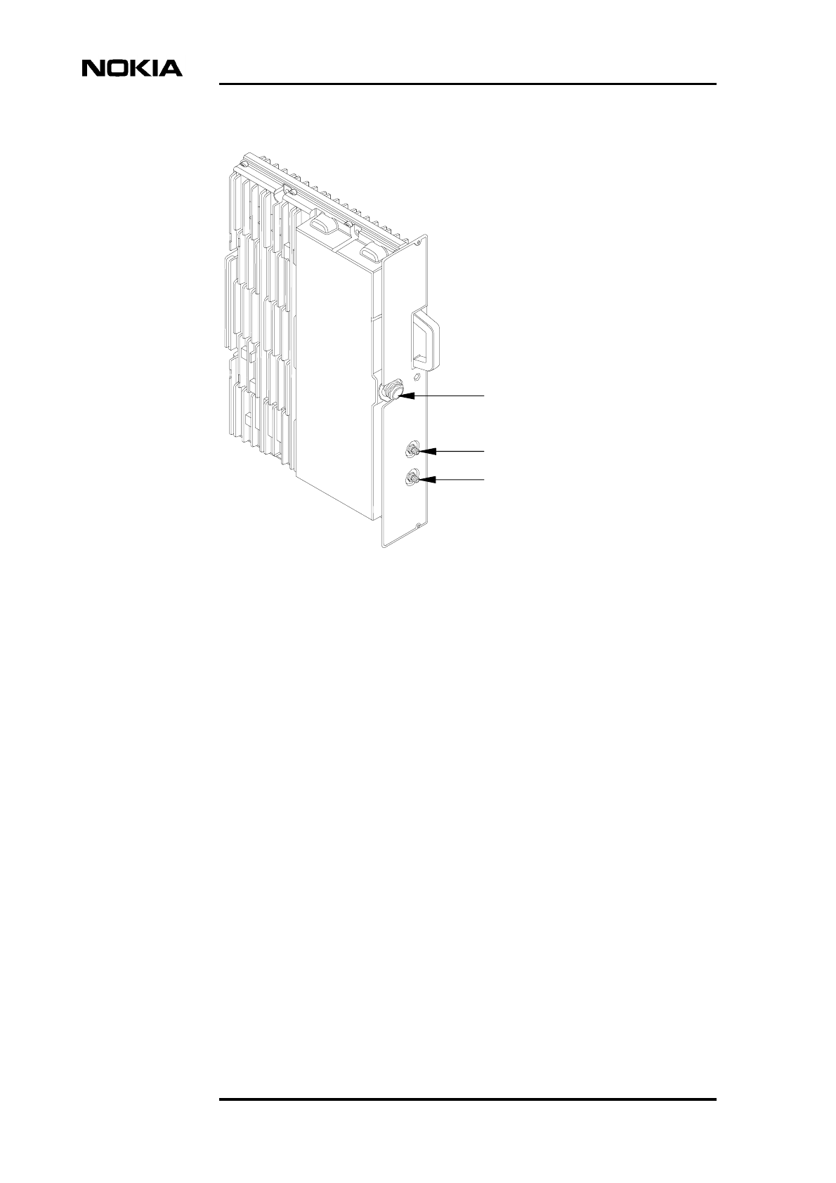
1. Slide the unit into the appropriate slot. See Figure 11.
2. Press each replacement unit carefully into the backplane to engage it in the
connector. Do not use excessive force!
3. Fix and tighten the unit retaining screws to 1.5 Nm (1.11 lb ft) using a T10
Torx screwdriver.
4. Reconnect the diversity cables to form the planned diversity configuration.
Refer to Nokia MetroSite EDGE Base Station: Installation for more
information on diversity cabling.
5. Reconnect the antenna connectors according to the sectoring solution
planned. Use a torque spanner/wrench to tighten the SMA type connectors
to 1 Nm (0.74 lb ft).
6. If new TRX units have been added to replace formerly empty slots (fitted
with shield units), route the associated cables through the cable entry block
and secure them with cable ties. See Figure 13.
The cable entry block must be removed in order to open it and route new
cables through. Use a torque driver with a 4 mm Allen bit to remove and
replace the two cable entry block screws.
7. Run the TRX test from Nokia BTS Manager (optional).
8. With Nokia BTS Manager, right-click the BCF object in the Equipment
View window and carry out a BCF Object Reset, or, if locked from the
BSC/NMS, request an unlock from the BSC/NMS (the BCF reset is
automatic in this case).

Replacing or installing new TRX units
DN00187365 © Nokia Corporation Draft 35 (50)
Issue 2-0 en Nokia Proprietary and Confidential
Note
9. If the green LED is lit on the TRX after the replacement procedure, the
BTS is in service. If the LED is yellow or red, check the alarms and run the
TRX test from the BSC/NMS.
5.2 Upgrading capacity by adding TRXs
The capacity of a single MetroSite EDGE BTS can be expanded to include up to
four TRXs. For information on coverage patterns and sectoring, refer to Nokia
MetroSite EDGE Base Station: Product Description.
The capacity of a MetroSite EDGE BTS can also be expanded by chaining. See
Chapter 6 of this document for information on Chaining Nokia MetroSite EDGE
BTSs.
The new TRX object must be created at the BSC/NMS before the new TRX can
start operation.
Adding a new TRX
1. Remove the shielding from the slot which is going to be populated with a
new TRX. Use a Torx T10 driver to remove the retaining screws of the
shielding unit.
2. Unpack the new TRX.
3. Insert the new TRX into the slot.
4. Connect your Nokia BTS Manager laptop PC to the LMP connector on the
interface unit. .
5. Select TRANSMISSION | TRAFFIC MANAGER from the main menu in
BTS Manager.
6. Allocate transmission capacity to the new TRX.
7. Run the TRX test from BTS Manager (optional).
8. If any objects are locked, unlock them from the BSC/NMS.
Field Upgrade
36 (50) © Nokia Corporation Draft DN00187365
Nokia Proprietary and Confidential Issue 2-0 en
Figure 11. Nokia MetroSite EDGE Base Station 5W GSM/EDGE TRX unit
Antenna connector
Diversity out
Diversity in

Chaining Nokia MetroSite EDGE BTSs
DN00187365 © Nokia Corporation Draft 37 (50)
Issue 2-0 en Nokia Proprietary and Confidential
6Chaining Nokia MetroSite EDGE BTSs
One or two Nokia MetroSite EDGE BTS cabinets can be added as slave cabinets
to a master BTS, increasing the capacity to anything between five and 12 TRXs
in one BCF object.
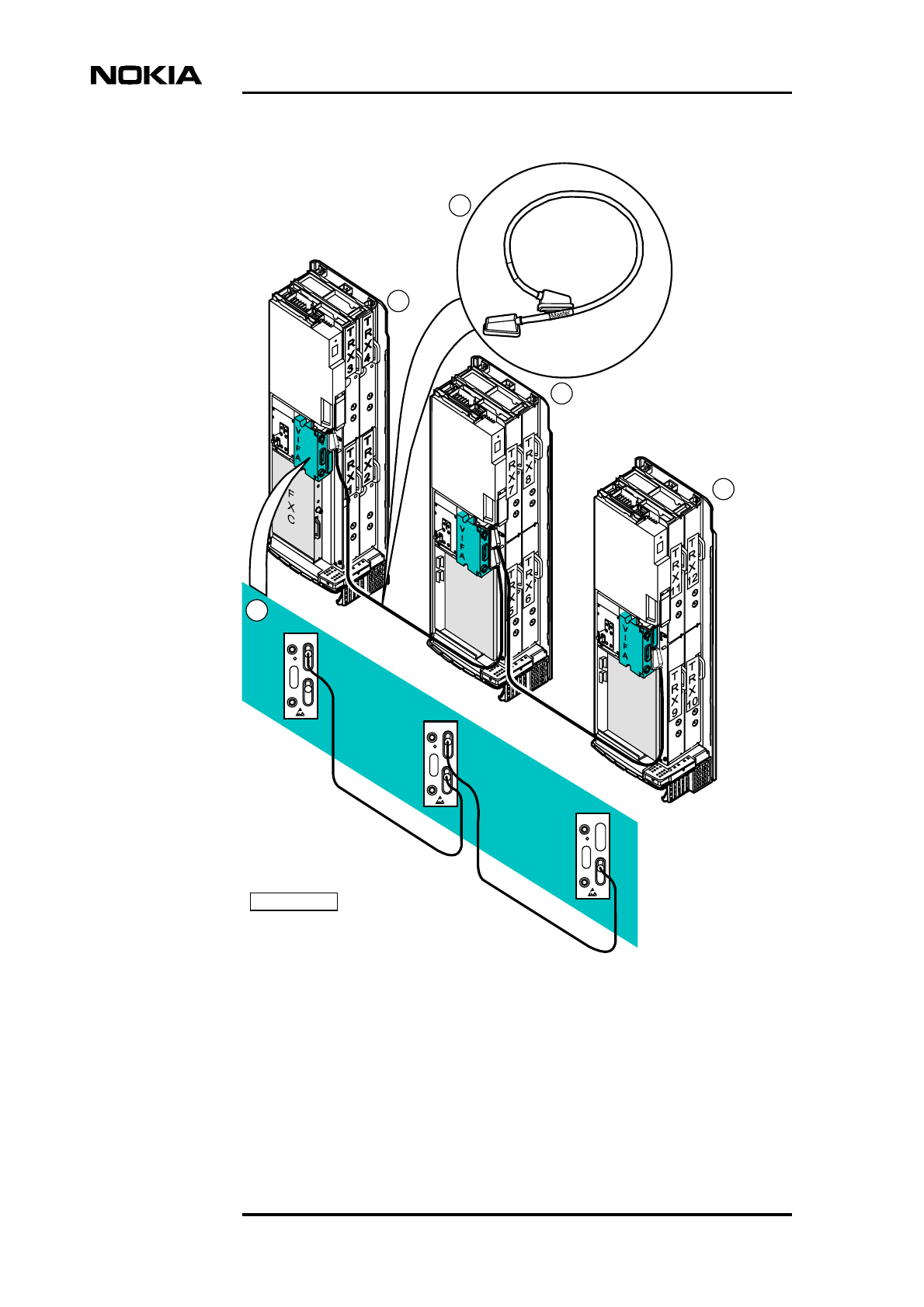
Chaining is done by connecting chaining cables from the interface unit (VIFA) of
the master BTS to the interface unit of the slave BTS. If a three cabinet chain is
required, a further cable is used to connect the first slave to the second slave in
series. See Figure 12 for an illustration of the chaining connection.
The following requirements apply to the chaining feature:
• An FXC transmission unit is required in the master BTS. The slave BTS
cabinets do not require a transmission unit.
• TRX 1 in the master BTS is the master TRX for the chained unit.
• CX 3.0 software or later must be loaded to the BTS from the BSC.
Field Upgrade
38 (50) © Nokia Corporation Draft DN00187365
Nokia Proprietary and Confidential Issue 2-0 en
Legend:
1 Connections at the VIFA interface units. A two BTS chain is
also possible. A termination connector is fitted to the first
(master cabinet) “EXT” connector in the chain (connector
supplied in the extension cable kit).
2 MetroSite BTS extension cable (chaining cable). The cable
has a “master” connector on one end and a “slave” connector
Slave
DN02107147
EXT
EXT
VIFA
EXT
EXT
VIFA
EXT
EXT
VIFA
1
3
2
4
5

Chaining Nokia MetroSite EDGE BTSs
DN00187365 © Nokia Corporation Draft 39 (50)
Issue 2-0 en Nokia Proprietary and Confidential
Note
at the other. Three different lengths of cable are available: 1,
3 and 5 metres.
3 Master BTS cabinet, with FXC transmission unit and TRXs 1
to 4. TRX 1 is the master TRX for the chain.
4 Slave BTS cabinet 1, with TRXs 5 to 8. Fewer TRXs are
possible. A transmission unit must not be fitted.
5 Slave BTS cabinet 2, with TRXs 9 to 12. Fewer TRXs are
possible. A transmission unit must not be fitted.
Figure 12. Chaining connection for three Nokia MetroSite EDGE base stations
6.1 Setting up a chaining connection
Follow the procedure to set up a chaining connection.
Connecting MetroSite BTSs in a chain
1. Refer to your upgrade/installation plan and install the extra BTS cabinets
as required. See the documents Nokia MetroSite EDGE Base Station:
Requirements for Installation and Operation and Nokia MetroSite EDGE
Base Station: Installation for instructions.
The longest extension cable available for chaining is five metres. Make sure that
you have got a suitable length of cable before mounting the extra BTS cabinets
for chaining.
2. Read Chapter 2 in this document, Preparing for upgrade, and familiarise
yourself with the precautions and procedures. Remove the cover of the
BTS.
3. Confirm that all the BTS cabinets in the planned chain have been mounted
correctly and contain the 5W GSM/EDGE TRXs as described in your site’s
transmission plan.
4. Confirm that the extra sectors and TRX have been added to the BCF in the
BSC database, and remain in the locked state.

Field Upgrade
40 (50) © Nokia Corporation Draft DN00187365
Nokia Proprietary and Confidential Issue 2-0 en
Note
Note
5. Request a BCF lock for the site from the BSC or NMS. You can check if
the site has been locked by connecting a BTS Manager laptop to the master
BTS in the chain, starting BTS Manager and checking TRX PROPERTIES
in the Supervision - Equipment View window (right-click with the mouse
over a TRX in the window).
6. Power OFF the master BTS. Inform your Operations Manager before doing
this and follow the procedures for powering down a BTS.
The site will already be “off air” if it has been locked.
Power OFF the master BTS by turning the switch on the power supply unit
to Stand-by.
7. On the master BTS, connect the end of the chaining cable marked “Master”
to the upper “EXT” connector on the interface unit. See Figure 12 for an
illustration of the connection.
8. On the slave BTS, connect the “slave” end of the cable which comes
coming from the master BTS to the lower “EXT” connector on the
interface unit. See Figure 12 for an illustration of the connection.
9. If a second slave BTS cabinet is required (making a three BTS chain),
connect the master end of the chaining cable from the upper “EXT”
connector on the first slave BTS to the lower “EXT” connector on the
interface unit of the second slave BTS (the third BTS in the chain). See
Figure 12 for an illustration of the connection.
10. Fit a termination connector to the first, unused lower “EXT” connector in
the chain. This will be in the master BTS, depending on the number of
BTSs in the chain.
11. Route the cables through the appropriate slots cable entry blocks on the
BTS cabinets and secure them with cable ties to the cable entry plate.
Figure 8 shows the cable entry block.
12. You can now commission the BTS. Follow the instructions given in
Chapter 7.2 of this document, Commissioning the BTS chain.
The newly chained BTS site should remain in the locked state until you have
completed the commissioning procedures. Do not request a BCF unlock until you
have commissioned the BTS chain.

Commissioning for upgrade
DN00187365 © Nokia Corporation Draft 41 (50)
Issue 2-0 en Nokia Proprietary and Confidential
Note
Note
Note
7Commissioning for upgrade
Whenever a Nokia MetroSite Base Station installation is upgraded to
GSM/EDGE or for BTS chaining it must be re-commissioned locally with Nokia
BTS Manager version 3.0 or later. This includes downloading the appropriate
software (CX 3.0 or later) to the master TRX from the BSC and configuring the
transmission.
To ensure that you have access to the correct software versions for the upgrade,
Nokia SiteWizard version 3.0 or later should be loaded on the laptop being used
for commissioning.
A Nokia MetroSite BTS installation fitted with 5W GSM/EDGE TRXs can be
commissioned for GSM transmission, EDGE transmission, or a combination of
both.
CX 3.2 software or later must be loaded at the BSC before BTS commissioning
for the EDGE and chaining upgrades. The software is downloaded to the TRXs
during the commissioning process with Nokia BTS Manager 3.x.

Field Upgrade
42 (50) © Nokia Corporation Draft DN00187365
Nokia Proprietary and Confidential Issue 2-0 en
7.1 Commissioning the BTS for GSM/EDGE
Commissioning the BTS for GSM/EDGE upgrade
1. Make sure that all the units and cables are installed and connected
correctly.
2. Connect the laptop PC loaded with Nokia BTS Manager 3.0 to the LMP
connector on the BTS’s interface unit. An LMP cable is required.
3. Switch ON the PSU at the BTS.
4. Start BTS Manager 3.0 on your laptop. Wait until Site Supervisory
condition is achieved. All units must show green LEDs.
5. With BTS Manager, uncommission the BTS. Follow the procedures found
in Nokia MetroSite EDGE Base Station: Commissioning.
6. Carry out the commissioning procedures as instructed in Nokia MetroSite
EDGE Base Station: Commissioning.
7. When commissioning is complete, disconnect the laptop from the BTS and
carry out the procedures in Chapter 8 of this document, Completing the
upgrade.
7.2 Commissioning the BTS chain
The chain of Nokia MetroSite EDGE base stations will be commissioned as one
BCF object, with TRX 1 in the master BTS performing the BCF traffic functions
for the chain. Otherwise, the master TRX in each cabinet controls only the
heating/cooling and alarm functions.
Commissioning the BTSs for a chaining upgrade
1. Make sure that all the units and cables are installed and connected
correctly.
2. Connect the laptop PC loaded with Nokia BTS Manager 3.0 to the LMP
connector on the interface unit of the master BTS. An LMP cable is
required.
3. Switch ON the PSUs at the master BTS and the slave BTSs.

Commissioning for upgrade
DN00187365 © Nokia Corporation Draft 43 (50)
Issue 2-0 en Nokia Proprietary and Confidential
Note
Note
Note
4. Start BTS Manager 3.0 on your laptop.
5. With BTS Manager, uncommission the master BTS by selecting
COMMISSIONING | WIZARD from the main menu and selecting the
‘Undo Commissioning’ button.
Before or during the commissioning of the BTS chain, CX 3.0 software must be
loaded to the master BTS from the BSC. CX 3.0 software or later must be
available at the BSC.
The newly chained BTS site should remain in the locked state until you have
completed the commissioning procedures. Do not request a BCF unlock until you
have commissioned the BTS chain.
6. Carry out the commissioning process with BTS Manager’s Commissioning
Wizard, as described in the document Nokia MetroSite EDGE Base
Station: Commissioning. At the stage of traffic allocation, follow the
instructions called Allocating transmission capacity for chaining in the
Traffic Manager chapter of the document.
It is important that when commissioning has been completed, the new BTS are
unlocked in the BSC database before the BCF is unlocked.
7. When commissioning is complete, disconnect the laptop from the master
BTS and carry out the procedures in Chapter 8 of this document,
Completing the upgrade.

Field Upgrade
44 (50) © Nokia Corporation Draft DN00187365
Nokia Proprietary and Confidential Issue 2-0 en

Completing the upgrade
DN00187365 © Nokia Corporation Draft 45 (50)
Issue 2-0 en Nokia Proprietary and Confidential
WARNING
8Completing the upgrade
GROUNDING. Before refitting the cabinet cover, make sure that the
grounding cable has been reconnected to the BTS cabinet.
Fitting the cabinet cover and completing the upgrade
1. Make sure that all the units and cables are correctly installed and
connected.
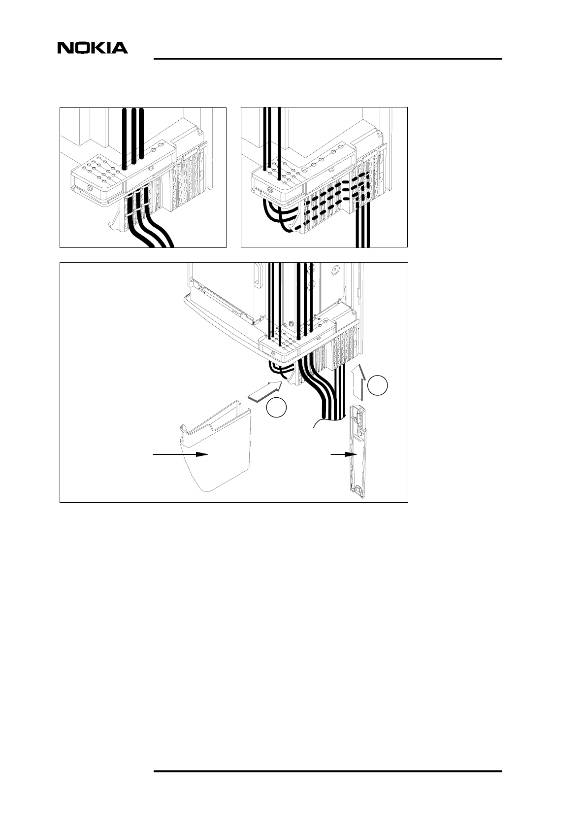
2. Fit the cable cover (see Figure 13) as follows:
a. Fit the cable cover support onto the hook at the end of the perforated
plastic panel.
b. Align the cable cover into the recesses on the cable cover support
and slide it downwards until it locks into place.
Field Upgrade
46 (50) © Nokia Corporation Draft DN00187365
Nokia Proprietary and Confidential Issue 2-0 en
Figure 13. Routing the cables and fitting the cable cover
3. Turn ON the external power supply switch.
4. Turn ON the PSU in the BTS.
A
B
Cable cover Cable cover
support
Completing the upgrade
DN00187365 © Nokia Corporation Draft 47 (50)
Issue 2-0 en Nokia Proprietary and Confidential
Note
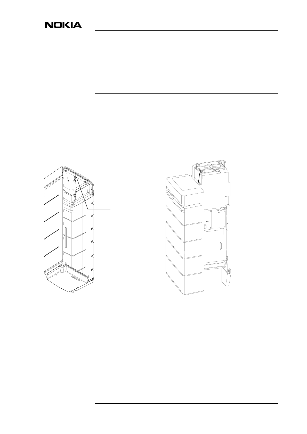
5. Refit the cabinet cover as follows (see also Figure 14):
If the Nokia MetroSite BTS installation was upgraded from 1W TRXs to 5W
TRXs, a new cover is required (HVCU type).
a. Attach the safety strap to the fixing point on the top of the cabinet.
b. Place the cover over the cabinet and align the locking hooks on the
cover to the locking rail on the chassis. Push the cover into the
chassis and pull downwards to lock the hooks firmly into the rail.
c. You can check that the cover is securely fastened by pushing on its
sides.
Figure 14. Nokia MetroSite EDGE BTS cover and safety strap
6. Lock the cabinet with the key.
7. Inform your Installation Manager / Site Manager that the upgrade is
complete and fill in the appropriate site reports.
Fixing point
for safety strap
under the
cover top

Field Upgrade
48 (50) © Nokia Corporation Draft DN00187365
Nokia Proprietary and Confidential Issue 2-0 en
Note
8. Recycle any applicable material.
In case you need to dispose of replaced units, contact Nokia Professional Services
for information on recycling. An environmental data package, including
disassembly instructions and a material balance document is also available via
Nokia Professional Services.

DN00187365 ©Nokia Corporation Draft 49 (50)
Issue 2-0 en Nokia Proprietary and Confidential
Index
upgrade types
GSM to GSM/EDGE 9
A
adding new TRXs to a BTS 35
antistatic wrist strap 18
B
blocking a TRX 33
BTS Manager 41
C
chaining 37
commissioning 41
cooling fan
HVMF, high capacity 28
installing 28
removing 25
VMFA 25
D
disposal of units 48
E
electro-static discharge protection 18
environmental conditions 16
environmental data package 48
equipment required for upgrade 17
G
grounding 45
I
installing
cover 45
high capacity cooling fan 28
PSU 23
TRX 31,34
M
master TRX 34
P
parts required for BTS chaining upgrade 15
parts required for GSM/EDGE upgrade 15
power supply precautions 13
power supply unit types 21
preparations for upgrade 13
R
removing
assemblycooling fan 25
cable entry block 25
cover 17
PSU 21
TRX 32
replacing
TRX 31
S
site, checking 16
software procedures 41
T
tools required for upgrade 17
transceiver unit (TRX)
blocking 33
installing 34
master 34
removing 32
slot order 32
unblocking 34
U
unblocking a TRX 34
upgrade types
1W to 5W TRX 9
capacity upgrade by chaining 11
capacity upgrade to a single BTS 35
W
working order for GSM/EDGE upgrade 9

Field Upgrade
50 (50) © Nokia Corporation Draft DN00187365
Nokia Proprietary and Confidential Issue 2-0 en
