Nokia Solutions and Networks WTPA-01 GSM 1900 Transceiver User Manual dn00112232x3x0xen
Nokia Solutions and Networks GSM 1900 Transceiver dn00112232x3x0xen
Contents
Alarms Desc

Nokia MetroSite EDGE Base Station
DN00112232 © Nokia Corporation Draft 1 (26)
Issue 3-0 en Nokia Proprietary and Confidential
Alarm Descriptions

Alarm Descriptions
2 (26) © Nokia Corporation Draft DN00112232
Nokia Proprietary and Confidential Issue 3-0 en
The information in this documentation is subject to change without notice and describes only
the product defined in the introduction of this documentation. This documentation is intended
for the use of Nokia's customers only for the purposes of the agreement under which the
documentation is submitted, and no part of it may be reproduced or transmitted in any form or
means without the prior written permission of Nokia. The documentation has been prepared to
be used by professional and properly trained personnel, and the customer assumes full
responsibility when using it. Nokia welcomes customer comments as part of the process of
continuous development and improvement of the documentation.
The information or statements given in this documentation concerning the suitability, capacity,
or performance of the mentioned hardware or software products cannot be considered binding
but shall be defined in the agreement made between Nokia and the customer. However, Nokia
has made all reasonable efforts to ensure that the instructions contained in the documentation
are adequate and free of material errors and omissions. Nokia will, if necessary, explain issues
which may not be covered by the documentation.
Nokia's liability for any errors in the documentation is limited to the documentary correction of
errors. NOKIA WILL NOT BE RESPONSIBLE IN ANY EVENT FOR ERRORS IN THIS
DOCUMENTATION OR FOR ANY DAMAGES, INCIDENTAL OR CONSEQUENTIAL
(INCLUDING MONETARY LOSSES), that might arise from the use of this documentation or
the information in it.
This documentation and the product it describes are considered protected by copyright
according to the applicable laws.
NOKIA logo is a registered trademark of Nokia Corporation.
Other product names mentioned in this documentation may be trademarks of their respective
companies, and they are mentioned for identification purposes only.
Copyright © Nokia Corporation 2002. All rights reserved.
DN00112232 © Nokia Corporation Draft 3 (26)
Issue 3-0 en Nokia Proprietary and Confidential
Hereby, Nokia Corporation, declares that this product is in compliance with the
essential requirements and other relevant provisions of Directive: 1999/5/EC.
The product is marked with the CE marking and Notified Body number according to the
Directive 1999/5/EC.
FCC FCC §15.21 - Information to user - This product is used as an intentional radiated
equipment and any changes or modifications on the equipment without any approval
by Nokia could void the user's authority to operate the equipment.
FCC §15.105 - Information to user - This equipment has been tested and found to
comply with the limits for a Class B digital device, pursuant to part 15 of the FCC
Rules. These limits are designed to provide reasonable protection against harmful
interference in a residential installation. This equipment generates, uses and can
radiate radio frequency energy and, if not installed and used in accordance with the
instructions, may cause harmful interference to radio communications. However, there
is no guarantee that interference will not occur in a particular installation. If this
equipment does cause harmful interference to radio or television reception, which can
be determined by turning the equipment off and on, the user is encouraged to try to
correct the interference by one or more of the following measures:
• Reorient or relocate the receiving antenna.
• Increase the separation between the equipment and receiver.
• Connect the equipment into an outlet on a circuit different from that to which the
receiver is connected.
• Consult the dealer or an experienced radio/TV technician for help.
0523

Alarm Descriptions
4 (26) © Nokia Corporation Draft DN00112232
Nokia Proprietary and Confidential Issue 3-0 en

DN00112232 © Nokia Corporation Draft 5 (26)
Issue 3-0 en Nokia Proprietary and Confidential
Contents
Contents 5
List of tables 6
List of figures 7
1 About this document 9
2 BTS alarm handling 11
2.1 Alarm examples 11
2.1.1 Alarms seen at the BSC or NMS 11
2.1.2 Alarms seen at the BTS 13
2.2 Troubleshooting faults 13
2.3 Fault reporting 14
2.4 Alarm reclassification 14
3 BTS alarm descriptions 17
3.1 Using an alarm description table 17
3.2 Alarm description tables 18

Alarm Descriptions
6 (26) © Nokia Corporation Draft DN00112232
Nokia Proprietary and Confidential Issue 3-0 en
List of tables
Table 1. Description of the fields in the alarm description table 17
Table 2. 7208 LOCAL BLOCK 18
Table 3. 7401 EXTERNAL ALARM 7401-7410, EXTERNAL ALARM 1-10 18
Table 4. 7600 BCF FAULTY 19
Table 5. 7601 BCF OPERATION DEGRADED 19
Table 6. 7602 BCF NOTIFICATION 20
Table 7. 7603 BTS FAULTY 21
Table 8. 7604 BTS OPERATION DEGRADED 21
Table 9. 7605 BTS NOTIFICATION 22
Table 10. 7606 TRX FAULTY 22
Table 11. 7607 TRX OPERATION DEGRADED 23
Table 12. 7609 TRE FAULTY 23
Table 13. 7615 RTS IN TEST USE 24
Table 14. 7616 OSCILLATOR ADJUSTMENT TEMPORARILY
INTERRUPTED 24
Table 15. 7617 SEVERAL CALLS DROPPED DUE PROBLEM WITH
TRANSCODER 24
Table 16. 7620 INCOMING POWER LOST 25
Table 17. 7621 INTOLERABLE CONDITIONS ON SITE 25
Table 18. 7622 CABINET OPEN 26
Table 19. 7801 MMI CONNECTED TO BASE STATION 26

DN00112232 © Nokia Corporation Draft 7 (26)
Issue 3-0 en Nokia Proprietary and Confidential
List of figures
Figure 1. Example 1, active alarms as seen at the BSC 12
Figure 2. Example 2, active alarm as seen at the BSC 12
Figure 3. Alarms view on Nokia MetroSite BTS Manager desktop 13
Figure 4. Faulty and degraded object alarm reclassification 15

Alarm Descriptions
8 (26) © Nokia Corporation Draft DN00112232
Nokia Proprietary and Confidential Issue 3-0 en
About this document
DN00112232 © Nokia Corporation Draft 9 (26)
Issue 3-0 en Nokia Proprietary and Confidential
Note
1About this document
This document provides information on the Nokia MetroSite EDGE Base Station
alarms. The alarms are used as a basis for internal fault recovery and fault
reporting to the BSC, NMS/2000 and/or the Nokia MetroSite BTS Manager
software.
This document also gives instructions for the operator on how to correct the faults
and maintain traffic in the air interface and/or to protect the units in the base
station.
This document does not include transmission unit alarms. Please refer to
appropriate transmission unit documentation.

Alarm Descriptions
10 (26) © Nokia Corporation Draft DN00112232
Nokia Proprietary and Confidential Issue 3-0 en

BTS alarm handling
DN00112232 © Nokia Corporation Draft 11 (26)
Issue 3-0 en Nokia Proprietary and Confidential
2BTS alarm handling
This chapter describes Nokia MetroSite EDGE Base Station alarm handling and
alarm reclassification. The fields in the alarm description table are also described.
2.1 Alarm examples
Alarms can be detected at the BSC, the NMS, or at the BTS. Instructions on how
to deal with the alarms is found in the alarm descriptions tables in Chapter 3 of
this document.
For instructions on how to replace units or carry out other maintenance tasks,
refer to Nokia MetroSite EDGE Base Station: Maintenance and Nokia MetroSite
Base Station: Field Upgrade.
2.1.1 Alarms seen at the BSC or NMS
Nokia MetroSite EDGE Base Station alarms issued at the BSC or NMS/2000
have a four-digit alarm number and an alarm name, together with the optional
fault reason (refer to Figures 1 and 2). For information on the other fields shown
in Figures 1 and 2, refer to BSC documentation.
Alarm Descriptions
12 (26) © Nokia Corporation Draft DN00112232
Nokia Proprietary and Confidential Issue 3-0 en
Note
Figure 1. Example 1, active alarms as seen at the BSC
Figure 2. Example 2, active alarm as seen at the BSC
The text below the alarm name describes the fault that has caused the alarm. For
example, in alarm [2] in Figure 1, the power supply unit is probably broken.
One alarm can have many different fault reasons.
In alarm [2] in Figure 1 the fault is different but the alarm number is the same as
in Figure 2. The effect on the operation of a base station is the same, which is why
they have the same alarm number and name.
BTS alarm handling
DN00112232 © Nokia Corporation Draft 13 (26)
Issue 3-0 en Nokia Proprietary and Confidential
2.1.2 Alarms seen at the BTS
Figure 3 shows how alarms (number, name and fault reason) are seen in the
Alarms view on the desktop of the Nokia MetroSite BTS Manager software.
Figure 3. Alarms view on Nokia MetroSite BTS Manager desktop
2.2 Troubleshooting faults
BTS alarms are described in detail in the alarm description tables found in
Chapter 3 of this document. Table 1 describes how to use the alarm description
tables.
Alarm Descriptions
14 (26) © Nokia Corporation Draft DN00112232
Nokia Proprietary and Confidential Issue 3-0 en
Note
Note
Troubleshooting faults using alarm description tables
1. Check the alarm number and alarm name and find its alarm description
table in Chapter 3 in this document.
2. Find the fault reason in the Fault reason field in the alarm description table.
3. Follow the instructions given in the Instruction field. See also the alarm
cancelling information in the Cancelling field.
4. If the fault reason cannot be found in the Fault reason field, follow the
instructions given for Other faults.
Instructions given for Other faults apply to several different fault reasons.
2.3 Fault reporting
Where possible, correct all damage, failures, and faults and report them to Nokia
using the Failure Report Form provided by Nokia Customer Services.
You can save the alarm information to a log file on your PC with Nokia MetroSite
BTS Manager.
2.4 Alarm reclassification
In fault situations, Nokia MetroSite EDGE Base Station runs an automatic
reclassification procedure for major (**) and critical (***) alarms before it sends
an alarm to the BSC. When an object becomes faulty, only one critical (***)
alarm from the object can be active at a time.
In reclassification, the alarm handling detects which logical base station object is
affected by a unit level fault. After reclassification, an object level alarm is issued
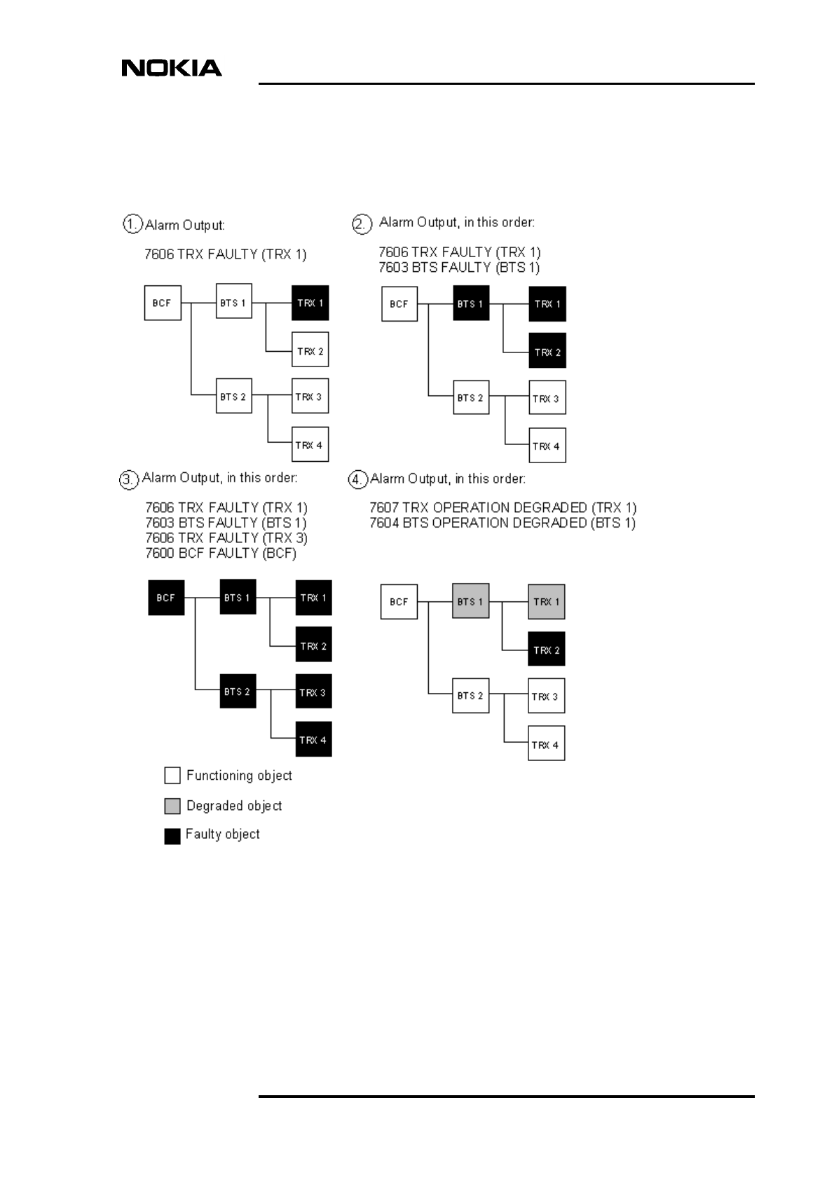
according to a certain hierarchy, as described in Figure 4.
BTS alarm handling
DN00112232 © Nokia Corporation Draft 15 (26)
Issue 3-0 en Nokia Proprietary and Confidential
Alarm Output in Figure 4 shows the number and the name of the alarm(s) issued
at the BSC in such a fault situation. Also, the object that is the alarm origin is
given in brackets.
Figure 4. Faulty and degraded object alarm reclassification
Fault situation [1]:
1. TRX 1 becomes disconnected and ceases to operate. 7606 TRX FAULTY
alarm is issued.

Alarm Descriptions
16 (26) © Nokia Corporation Draft DN00112232
Nokia Proprietary and Confidential Issue 3-0 en
Fault situation [2]:
1. TRX 1 becomes disconnected and ceases to operate. 7606 TRX FAULTY
alarm is issued.
2. TRX 2 becomes disconnected, which causes BTS 1 cease to operate. Alarm
reclassification discards the new TRX alarm and a BTS alarm, 7603 BTS
FAULTY, is issued.
Fault situation [3]:
1. TRX 1 becomes disconnected and ceases to operate. 7606 TRX FAULTY
alarm is issued.
2. TRX 2 becomes disconnected, which causes BTS 1 cease to operate. Alarm
reclassification discards the new TRX alarm and a BTS alarm, 7603 BTS
FAULTY, is issued.
3. TRX 3 becomes disconnected, and another 7606 TRX FAULTY alarm is
issued.
4. TRX 4 becomes disconnected, which causes BTS 2 cease to operate. Now
both sectors in the BCF are not operating. Alarm reclassification discards
both the new TRX alarm and the new BTS alarm, and a BCF alarm, 7600
BCF FAULTY, is issued.
Fault situation [4]:
1. TRX 1 becomes partially faulty but calls are getting through. 7607 TRX
OPERATION DEGRADED alarm is issued.
2. TRX 2 becomes disconnected and ceases to operate. Alarm reclassification
discards the new TRX alarm and a BTS alarm, 7604 BTS OPERATION
DEGRADED, is issued.
BTS alarm descriptions
DN00112232 © Nokia Corporation Draft 17 (26)
Issue 3-0 en Nokia Proprietary and Confidential
3BTS alarm descriptions
This chapter defines the alarms collected from the objects in the Nokia MetroSite
EDGE Base Station.
3.1 Using an alarm description table
Table 1 describes the information that you will find in the alarm description tables
for the Nokia MetroSite EDGE Base Station. A full list of the alarm tables is
given in Chapter 3.2 of this document.
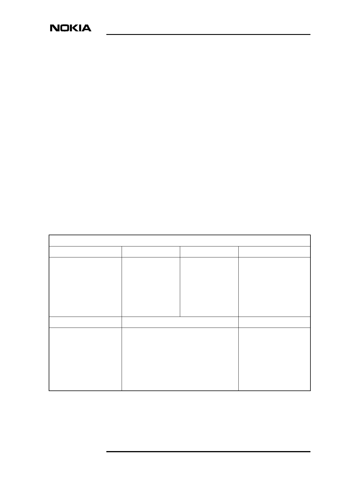
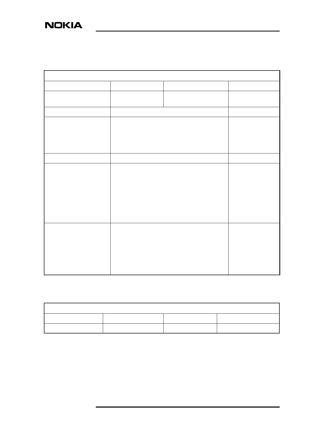
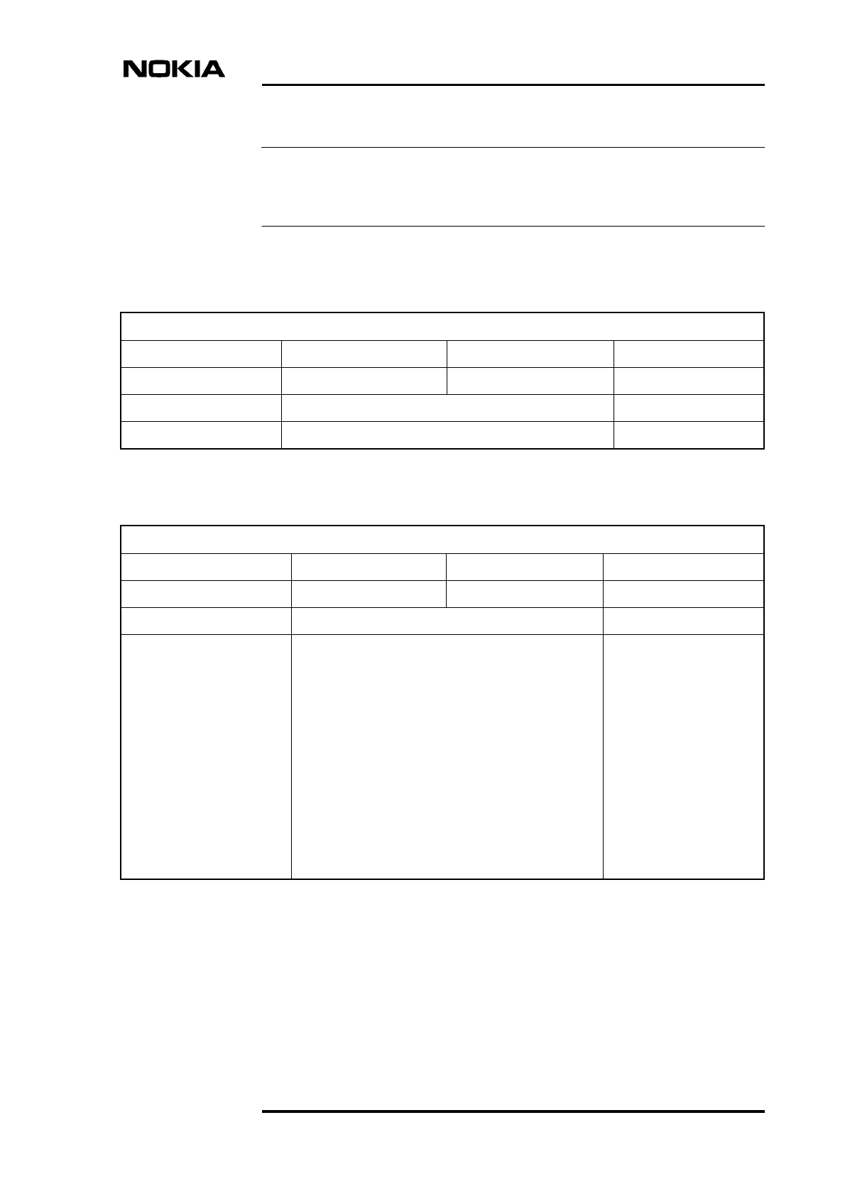
Table 1. Description of the fields in the alarm description table
1234 ALARM NAME
Severity: Object affected: Object state: Unit:
Shows the alarm severity as
displayed at the BSC or
NMS/2000. The options are:
• * = minor
• ** = major
• *** = critical
• User definition
The logical object
affected by the fault.
The options are:
BCF, BTS, TRX, TRE,
RTS
The state of the
affected object at the
time the alarm is
issued. The options
are:
• Enabled
• Disabled
The alarm origin(s). The unit
is given a four-letter
acronym, e.g.:
WTxx, HVTx, VXxx, VIFA
Fault reason: Instruction: Alarm cancelling:
This field describes the
cause of the alarm, for
example:
Power unit is probably
broken.
This field gives instructions for the operator (at
the NMS/2000 or at the BSC) how to correct the
fault reason causing the alarm:
1. If the power supply unit LED is green, check
the TRXs and replace the faulty TRX. The
TRX connectors are probably broken.
2. If the power supply unit LED is red, replace
the power supply unit.
This field describes how the
alarm is cancelled. The
options are:
• Automatic
• Manual
Alarm Descriptions
18 (26) © Nokia Corporation Draft DN00112232
Nokia Proprietary and Confidential Issue 3-0 en
Note
3.2 Alarm description tables
The alarms from the blocked object are cancelled.
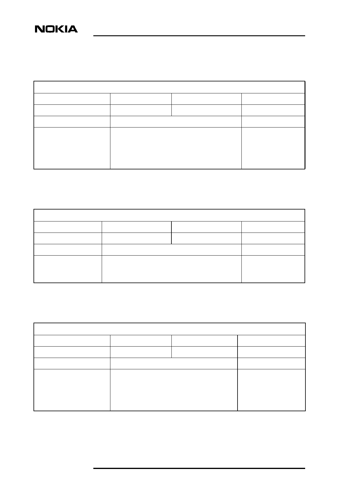
Table 2. 7208 LOCAL BLOCK
7208 LOCAL BLOCK
Severity: Object affected: Object state: Unit:
* BCF, or BTS, or TRX Disabled WTxx, HVTx
Fault reason: Instruction: Alarm cancelling:
No fault reason text with the
alarm.
Nokia MetroSite BTS object
is blocked with Nokia BTS
Manager.
1. No actions required. Automatic.
Table 3. 7401 EXTERNAL ALARM 7401-7410, EXTERNAL ALARM 1-10
7401 EXTERNAL ALARM 7401 - 7410, EXTERNAL ALARM 1 - 10
Severity: Object affected: Object state: Unit:
User definition BCF Enabled WTxx, HVTx
Fault reason: Instruction: Alarm cancelling:
No fault reason text with the
alarm.
This is an external user-
definable alarm.
1. Check the settings at the BSC.
2. Check the cable connected to the VIFA unit in the
base station.
3. Check the unit connected to the external alarm
line.
4. If all of the above are OK, replace the VIFA plug-in
unit.
Automatic.
BTS alarm descriptions
DN00112232 © Nokia Corporation Draft 19 (26)
Issue 3-0 en Nokia Proprietary and Confidential
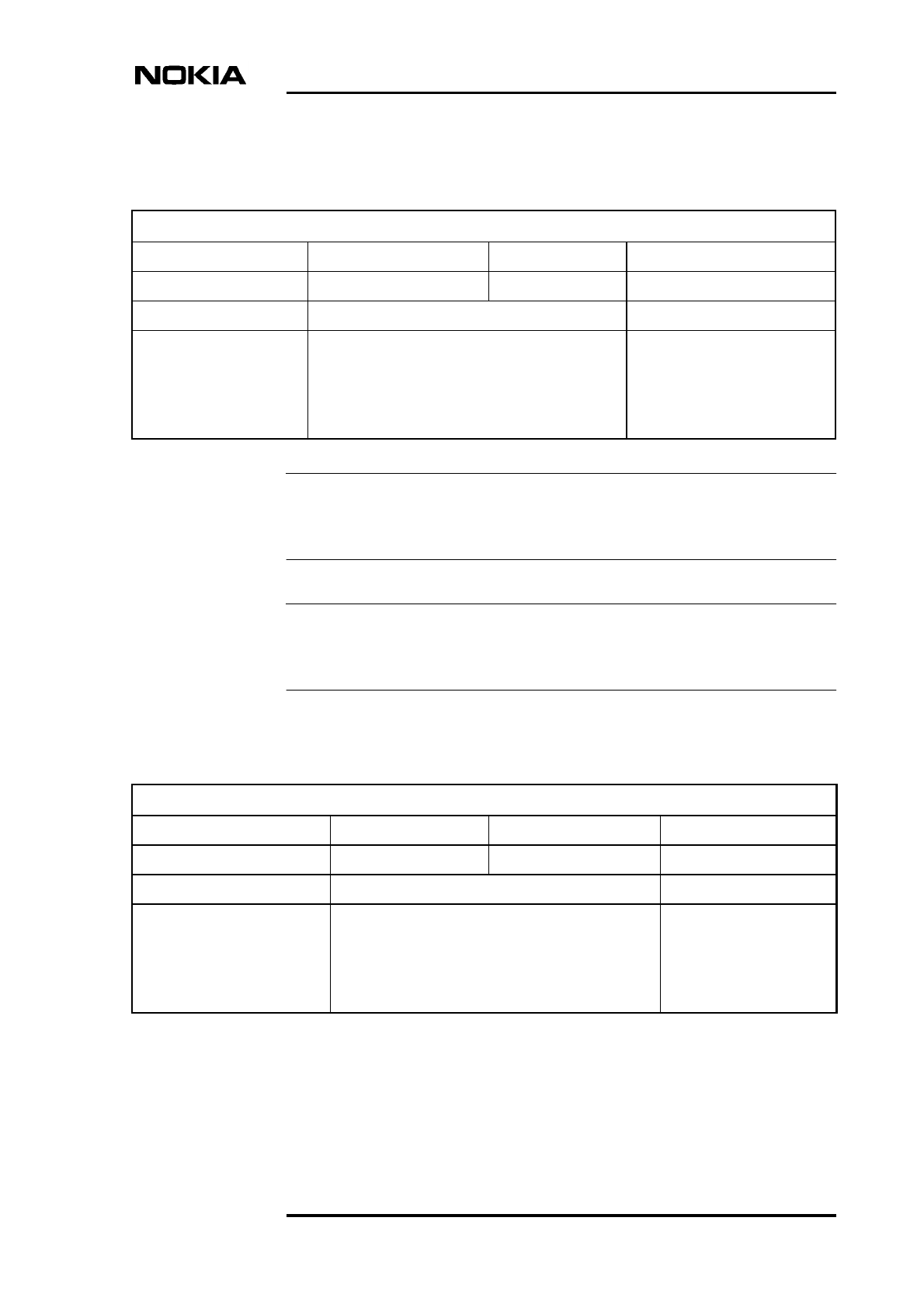
Table 4. 7600 BCF FAULTY
7600 BCF FAULTY
Severity: Object affected: Object state: Unit:
*** BCF Disabled WTxx, HVTx, HVSx,
VIFA
Fault reason: Instruction: Alarm cancelling:
Power unit is probably
broken.
1. If the power supply unit LED is green, check the
TRXs and replace the faulty TRX. TRX connectors
are probably broken.
2. If the power supply unit LED is red, replace the
power supply unit.
Automatic.
Oven oscillator is broken. 1. Replace the VIFA unit. Automatic.
Temperature inside the TRX
is dangerously high.
1. Check whether the following alarm is active:
7621 INTOLERABLE CONDITIONS ON SITE
and follow the instructions given for the alarm.
2. Even if alarm 7621 is not active, and there is only
one TRX in the cabinet, follow the instructions
given for alarm 7621.
3. If alarm 7621 is not active and the cabinet has
more than one TRX, replace the master TRX.
Automatic.
Other faults. 1. Check whether either of the following alarms is
active:
7606 TRX FAULTY
7603 BTS FAULTY
and follow the instructions given for the active
alarm(s). If necessary, replace all TRXs in the
cabinet.
Automatic.
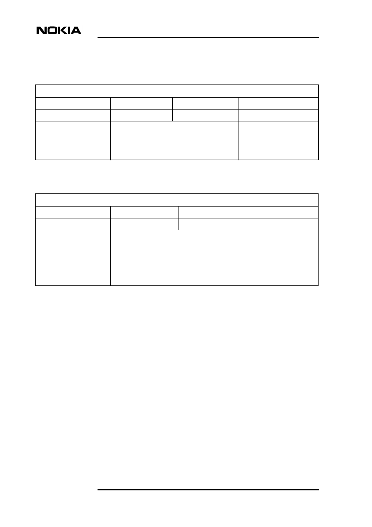
Table 5. 7601 BCF OPERATION DEGRADED
7601 BCF OPERATION DEGRADED
Severity: Object affected: Object state: Unit:
** BCF Enabled WTxx, HVTx
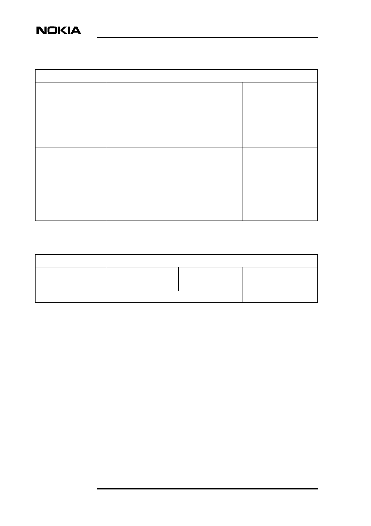
Alarm Descriptions
20 (26) © Nokia Corporation Draft DN00112232
Nokia Proprietary and Confidential Issue 3-0 en
Fault reason: Instruction: Alarm cancelling:
Cabinet I2 C bus is
jammed.
1. Switch the site power Off and On.
2. Check the fan unit, the power supply unit and the
TRXs. If necessary, replace the faulty unit(s).
3. If the fault reappears, replace the cabinet. The
units inside the cabinet can be reused in the new
cabinet.
Automatic.
Other faults. 1. Check whether one or several of the following
alarms are active:
7606 TRX FAULTY
7603 BTS FAULTY
7607 TRX OPERATION DEGRADED
7604 BTS OPERATION DEGRADED
and follow the instructions given for the active
alarm(s).
Automatic.
Table 5. 7601 BCF OPERATION DEGRADED (Continued)
7601 BCF OPERATION DEGRADED
Table 6. 7602 BCF NOTIFICATION
7602 BCF NOTIFICATION
Severity: Object affected: Object state: Unit:
* BCF Enabled WTxx, HVTx, HVMF
Fault reason: Instruction: Alarm cancelling:
BTS alarm descriptions
DN00112232 © Nokia Corporation Draft 21 (26)
Issue 3-0 en Nokia Proprietary and Confidential
Temperature inside the
TRX is high.
1. Check whether the following alarm is active for
fan unit:
7605 BTS NOTIFICATION
and follow the instructions given for the alarm.
2. Even if there are no active alarms for the fan
unit, check that no foreign objects obstruct the
airflow.
3. If alarm 7605 is not active, ensure that the
ambient temperature of the base station is within
acceptable limits.
Automatic.
Temperature inside the
TRX is low.
1. Ensure that the ambient temperature is within
acceptable limits. Check also the fan unit.
Automatic.
Fan unit is broken. 1. Check whether the fan unit is installed.
2. When there is a fan unit installed, check if
something has jammed the fan unit and remove
the jamming object. Otherwise replace the fan
unit.
Automatic.
Table 6. 7602 BCF NOTIFICATION (Continued)
7602 BCF NOTIFICATION
Table 7. 7603 BTS FAULTY
7603 BTS FAULTY
Severity: Object affected: Object state: Unit:
*** BTS Disabled WTxx, HVTx
Fault reason: Instruction: Alarm cancelling:
Other faults. 1. Check whether the following alarm is active:
7606 TRX FAULTY
and follow the instructions given for the alarm. If
necessary, replace all TRXs in the faulty sector.
Automatic.
Table 8. 7604 BTS OPERATION DEGRADED
7604 BTS OPERATION DEGRADED
Severity: Object affected: Object state: Unit:
Alarm Descriptions
22 (26) © Nokia Corporation Draft DN00112232
Nokia Proprietary and Confidential Issue 3-0 en
** BTS Enabled WTxx, HVTx
Fault reason: Instruction: Alarm cancelling:
Other faults. 1. Check whether either of the following alarms is
active:
7606 TRX FAULTY
7607 TRX OPERATION DEGRADED
and follow the instructions given for the active
alarm(s).
Automatic.
Table 8. 7604 BTS OPERATION DEGRADED (Continued)
7604 BTS OPERATION DEGRADED
Table 9. 7605 BTS NOTIFICATION
7605 BTS NOTIFICATION
Severity: Object affected: Object state: Unit:
* BTS Enabled HVMF
Fault reason: Instruction: Alarm cancelling:
Fan unit operation
degraded.
1. If something has jammed the fan unit, remove the
jamming object. Otherwise replace the fan unit.
Automatic.
Table 10. 7606 TRX FAULTY
7606 TRX FAULTY
Severity: Object affected: Object state: Unit:
** TRX Disabled WTxx, HVTx
Fault reason: Instruction: Alarm cancelling:
Failure detected during TRX
configuring.
1. The TRX has become disconnected. Reconnect
the cabling at the TRX.
Automatic.
Antenna connection faulty. 1. Check the antenna and cabling. If the antenna
and cabling are faulty, correct the problem and
run TRX test to cancel the alarm.
Manual/Automatic.
TRX test result antenna
connection faulty.
1. Check the antenna and cabling. If the antenna
and cabling are faulty, correct the problem and
run TRX test again to cancel the alarm.
Manual/Automatic.
BTS alarm descriptions
DN00112232 © Nokia Corporation Draft 23 (26)
Issue 3-0 en Nokia Proprietary and Confidential
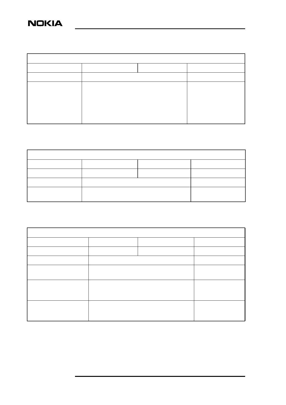
Note
In case of alarm 7606, if a BCCH TRX is affected, the BSC performs a BCCH
reconfiguration if possible.
Table 11. 7607 TRX OPERATION DEGRADED
7607 TRX OPERATION DEGRADED
Severity: Object affected: Object state: Unit:
** TRX Enabled WTxx, HVTx
Fault reason: Instruction: Alarm cancelling:
Other faults. 1. Replace the faulty TRX. Automatic.
Table 12. 7609 TRE FAULTY
7609 TRE FAULTY
Severity: Object affected: Object state: Unit:
*** BCF Disabled VXxx
Fault reason: Instruction: Alarm cancelling:
Master TRX detected that
connection to transmission
unit is lost.
1. If the alarm is seen at the BSC, the transmission
unit is not working properly. However, if the base
station otherwise operates properly, there is no
need for immediate repair. The transmission
alarms are not reported to the BSC.
2. If the alarm is seen on Nokia BTS Manager only,
the transmission unit is not operating. Reset the
BCF.
3. If the alarm reappears after BCF reset, switch
the cabinet power off and on.
4. If the alarm reappears after the recovery actions
above, replace the faulty transmission plug-in
unit.
Manual/Automatic.
Alarm Descriptions
24 (26) © Nokia Corporation Draft DN00112232
Nokia Proprietary and Confidential Issue 3-0 en
Table 13. 7615 RTS IN TEST USE
7615 RTS IN TEST USE
Severity: Object affected: Object state: Unit:
* RTS Disabled WTxx, HVTx
Fault reason: Instruction: Alarm cancelling:
No fault reason text with the
alarm.
Internal O&M SW is testing
the timeslots during TRX
test.
1. No actions required. Automatic.
Table 14. 7616 OSCILLATOR ADJUSTMENT TEMPORARILY
INTERRUPTED
7616 OSCILLATOR ADJUSTMENT TEMPORARILY INTERRUPTED
Severity: Object affected: Object state: Unit:
* BCF Enabled VIFA
Fault reason: Instruction: Alarm cancelling:
Oven oscillator
adjustment function
interrupted.
1. Check the Abis connection.
2. If the Abis connection is OK, replace the faulty VIFA
unit.
Automatic.
Table 15. 7617 SEVERAL CALLS DROPPED DUE PROBLEM WITH
TRANSCODER
7617 SEVERAL CALLS DROPPED DUE PROBLEM WITH TRANSCODER
Severity: Object affected: Object state: Unit:
** TRX Enabled WTxx, HVTx
Fault reason: Instruction: Alarm cancelling:
Other faults.
There is an error with the
connection between the
base station and the
transcoder.
1. Check the transmission path between the base
station and the transcoder.
Automatic/Manual.
BTS alarm descriptions
DN00112232 © Nokia Corporation Draft 25 (26)
Issue 3-0 en Nokia Proprietary and Confidential
Note
Note
When alarm 7620 is active, it will not be sent to Nokia BTS Manager. However,
alarm cancelling can be seen on Nokia BTS Manager.
In case of alarm 7620, if the power loss is very short and the power is on again
within 1500 ms, the alarm is cancelled automatically. No actions required.
Table 16. 7620 INCOMING POWER LOST
7620 INCOMING POWER LOST
Severity: Object affected: Object state: Unit:
* BCF Enabled HVSx
Fault reason: Instruction: Alarm cancelling:
No fault reason text with
the alarm.
Base station power
supply unit has lost its
main power.
1. Check the mains supply.
2. If the mains supply is OK, replace the power
supply unit.
Automatic.
Table 17. 7621 INTOLERABLE CONDITIONS ON SITE
7621 INTOLERABLE CONDITIONS ON SITE
Severity: Object affected: Object state: Unit:
* BCF Enabled WTxx, HVTx
Fault reason: Instruction: Alarm cancelling:
Temperature inside the TRX
is dangerously high.
1. Check that the fan unit is operating.
2. If the fan unit is OK, ensure that the
environment of the base station site meets the
conditions specified for Nokia MetroSite EDGE
Base Station.
Automatic.
Alarm Descriptions
26 (26) © Nokia Corporation Draft DN00112232
Nokia Proprietary and Confidential Issue 3-0 en
Table 18. 7622 CABINET OPEN
7622 CABINET OPEN
Severity: Object affected: Object state: Unit:
* BCF Enabled HVCU, WCUA
Fault reason: Instruction: Alarm cancelling:
Cabinet cover is open. 1. If the cover is attached, ensure it is secured
properly. If there is no cover, attach it during
normal service operations.
Automatic.
Table 19. 7801 MMI CONNECTED TO BASE STATION
7801 MMI CONNECTED TO BASE STATION
Severity: Object affected: Object state: Unit:
* BCF Enabled WTxx, HVTx
Fault reason: Instruction: Alarm cancelling:
No fault reason text with
the alarm.
Nokia BTS Manager is
connected to Nokia
MetroSite BTS.
1. No actions required. Automatic.