Nokia Solutions and Networks WTPA-01 GSM 1900 Transceiver User Manual dn99252966x3x0xen
Nokia Solutions and Networks GSM 1900 Transceiver dn99252966x3x0xen
Contents
Solution Accessories

Nokia MetroSite EDGE Base Station
DN99252966 © Nokia Corporation Draft 1 (66)
Issue 3-0 en Nokia Proprietary and Confidential
Solution Accessories

Solution Accessories
2 (66) © Nokia Corporation Draft DN99252966
Nokia Proprietary and Confidential Issue3-0en
The information in this documentation is subject to change without notice and describes only
the product defined in the introduction of this documentation. This documentation is intended
for the use of Nokia's customers only for the purposes of the agreement under which the
documentation is submitted, and no part of it may be reproduced or transmitted in any form or
means without the prior written permission of Nokia. The documentation has been prepared to
be used by professional and properly trained personnel, and the customer assumes full
responsibility when using it. Nokia welcomes customer comments as part of the process of
continuous development and improvement of the documentation.
The information or statements given in this documentation concerning the suitability, capacity,
or performance of the mentioned hardware or software products cannot be considered binding
but shall be defined in the agreement made between Nokia and the customer. However, Nokia
has made all reasonable efforts to ensure that the instructions contained in the documentation
are adequate and free of material errors and omissions. Nokia will, if necessary, explain issues
which may not be covered by the documentation.
Nokia's liability for any errors in the documentation is limited to the documentary correction of
errors. NOKIA WILL NOT BE RESPONSIBLE IN ANY EVENT FOR ERRORS IN THIS
DOCUMENTATION OR FOR ANY DAMAGES, INCIDENTAL OR CONSEQUENTIAL
(INCLUDING MONETARY LOSSES), that might arise from the use of this documentation or
the information in it.
This documentation and the product it describes are considered protected by copyright
according to the applicable laws.
NOKIA logo is a registered trademark of Nokia Corporation.
Other product names mentioned in this documentation may be trademarks of their respective
companies, and they are mentioned for identification purposes only.
Copyright © Nokia Corporation 2002. All rights reserved.
DN99252966 © Nokia Corporation Draft 3 (66)
Issue 3-0 en Nokia Proprietary and Confidential
Hereby, Nokia Corporation, declares that this product is in compliance with the
essential requirements and other relevant provisions of Directive: 1999/5/EC.
The product is marked with the CE marking and Notified Body number according to the
Directive 1999/5/EC.
FCC FCC §15.21 - Information to user - This product is used as an intentional radiated
equipment and any changes or modifications on the equipment without any approval
by Nokia could void the user's authority to operate the equipment.
FCC §15.105 - Information to user - This equipment has been tested and found to
comply with the limits for a Class B digital device, pursuant to part 15 of the FCC
Rules. These limits are designed to provide reasonable protection against harmful
interference in a residential installation. This equipment generates, uses and can
radiate radio frequency energy and, if not installed and used in accordance with the
instructions, may cause harmful interference to radio communications. However, there
is no guarantee that interference will not occur in a particular installation. If this
equipment does cause harmful interference to radio or television reception, which can
be determined by turning the equipment off and on, the user is encouraged to try to
correct the interference by one or more of the following measures:
• Reorient or relocate the receiving antenna.
• Increase the separation between the equipment and receiver.
• Connect the equipment into an outlet on a circuit different from that to which the
receiver is connected.
• Consult the dealer or an experienced radio/TV technician for help.
0523

Solution Accessories
4 (66) © Nokia Corporation Draft DN99252966
Nokia Proprietary and Confidential Issue3-0en
DN99252966 © Nokia Corporation Draft 5 (66)
Issue 3-0 en Nokia Proprietary and Confidential
Contents
Contents 5
List of tables 7
List of figures 9
Summary of changes 11
1 About this document 13
2 Accessories and specifications 15
2.1 Flexbus accessories 15
2.1.1 Flexbus cable specifications 15
2.1.2 TNC male connector specifications (straight and right-angled) 17
2.2 Local Management Port accessories 20
2.2.1 Q1 LMP cable specifications 20
2.3 Abis PCM cable 21
2.3.1 PCM cable 75 ohm 22
2.3.2 PCM cable 120 ohm 22
2.3.3 BT43 plug 23
2.3.4 TQ plug 23
2.4 MetroSite antennas 23
2.4.1 MetroSite 130o panel antenna 24
2.4.2 MetroSite XX-pol panel antenna 26
2.4.3 Omni dual band antenna 31
2.4.4 Indoor omni multi-band antenna 34
2.4.5 Indoor multi-band panel antenna 35
2.4.6 Pole mounting clamps (50-115 mm pole diameter) 37
2.5 GSM/EDGE 900, 1800 and 1900 combiners 38
2.6 Antenna lines 42
2.6.1 Antenna line cables 42
2.6.2 N male connector: straight 45
2.6.3 N male connector: right angled 46
2.6.4 7-16 Straight Male connector 48
2.7 MetroSite Battery Backup Unit 49
2.7.1 Battery Backup Unit 49
2.7.2 Mains power cable (230 VAC) 49
2.7.3 230/110 VAC output cable 50
2.7.4 Alarm cable 51
2.7.5 Battery connection kit 52
2.8 Miscellaneous 53
2.8.1 Jumper cables 54
2.8.2 Grounding cable 54
2.8.3 AC power cables for MetroSite BTS or MetroHub 55
2.8.4 DC power cable for MetroSite BTS or MetroHub 56
2.8.5 Optical Alignment Tool 57
3 Attachments 59


DN99252966 © Nokia Corporation Draft 7 (66)
Issue 3-0 en Nokia Proprietary and Confidential
List of tables
Table 1. Flexbus accessories for the MetroSite EDGE Base Station 15
Table 2. Flexbus cable specifications 17
Table 3. LMP accessories for the MetroSite EDGE Base Station 20
Table 4. LMP cable connector specifications 20
Table 5. Abis PCM cable and accessories 21
Table 6. PCM cable 75 Ω specifications 22
Table 7. PCM cable 120 Ω specifications 22
Table 8. Antennas for the Nokia MetroSite EDGE Base Station 23
Table 9. Specifications for the 130o antenna 25
Table 10. Specifications for the MetroSite XX-pol 900/1800 MHz panel antenna 27
Table 11. Specifications for the MetroSite XX-pol 850/1900 MHz panel antenna 30
Table 12. Specifications for the omni-directional 900/1800 MHz dual band
antenna 31
Table 13. Specifications for the omni-directional 850/1900 MHz dual band
antenna 33
Table 14. Specifications for the indoor omni multi-band antenna 35
Table 15. Specifications for the indoor multi-band panel antenna 36
Table 16. Combiners for the Nokia MetroSite EDGE Base Station 38
Table 17. Specifications for the GSM/EDGE combiners 40
Table 18. Antenna line accessories for the Nokia MetroSite EDGE Base
Station 42
Table 19. Sheath characteristics for the antenna line cable 43
Table 20. Cable characteristics for the antenna line cable 43
Table 21. Attenuation and power characteristics for the antenna line cable 44
Table 22. Specifications for the N male connector 46
Table 23. Specifications for the N male connector, right angled 47
Table 24. Specifications for the N male connector, right angled 48
Table 25. Specifications for the 230 VAC mains power cable 50
Table 26. Specifications for the 230/110 VAC mains power cable 51
Table 27. Specifications for the alarm cable 52

Solution Accessories
8 (66) © Nokia Corporation Draft DN99252966
Nokia Proprietary and Confidential Issue3-0en
Table 28. Contents of the battery connection kit 52
Table 29. Miscellaneous accessories for the Nokia MetroSite EDGE Base
Station 53
Table 30. Jumper cable accessories 54
Table 31. Grounding cable specifications 54
Table 32. Specifications for the 230 VAC power cable 55
Table 33. Specifications for the 110 VAC power cable 56
Table 34. Specifications for the DC power cable 56
Table 35. Specifications for the optical alignment tool 58

DN99252966 © Nokia Corporation Draft 9 (66)
Issue 3-0 en Nokia Proprietary and Confidential
List of figures
Figure 1. Flexbus cable 16
Figure 2. TNC connectors 19
Figure 3. LMP cable and connectors 21
Figure 4. MetroSite 130o panel antenna 25
Figure 5. MetroSite XX-pol 900/1800 MHz panel antenna 27
Figure 6. MetroSite XX-pol 850/1900 MHz panel antenna 29
Figure 7. Omni-directional dual band 900/1800 MHz antenna 31
Figure 8. Omni-directional dual band 850/1900 MHz antenna 33
Figure 9. Indoor omni multi-band antenna 34
Figure 10. Indoor multi-band panel antenna 36
Figure 11. Installing the indoor multi-band panel antenna 37
Figure 12. Antenna pole mounting clamp 38
Figure 13. GSM/EDGE combiner 39
Figure 14. Dimensions of the GSM/EDGE combiner 40
Figure 15. Antenna line cable 43
Figure 16. N male connector 45
Figure 17. N male connector, right angled 47
Figure 18. 7-16 Straight male connector 48
Figure 19. Battery connection kit 53
Figure 20. Optical alignment tool 57

Solution Accessories
10 (66) © Nokia Corporation Draft DN99252966
Nokia Proprietary and Confidential Issue3-0en

DN99252966 © Nokia Corporation Draft 11 (66)
Issue 3-0 en Nokia Proprietary and Confidential
Summary of changes
Version 1-0, 5th March, 1999. Norman M. Thomas.
Version 2-0, 30th August 2001. Tyrone Williams.
Version 3-0, August 2002. Kudos (Celia Pires, Mark Seymour). Added chaining
extension cables into “Miscellaneous”, made corrections to specifications
following comments from Jan Ekman, Tomi Karvonen and Peter Berghall.
Version 3-0, October 2002. Kudos (Mark Seymour). Product codes updated.
800/1900 MHz antennas added.

Solution Accessories
12 (66) © Nokia Corporation Draft DN99252966
Nokia Proprietary and Confidential Issue3-0en

About this document
DN99252966 © Nokia Corporation Draft 13 (66)
Issue 3-0 en Nokia Proprietary and Confidential
1About this document
This document lists the Nokia accessories which are available to support the
Nokia MetroSiteTM Base Station. Descriptions and specifications of the
accessories are also included.
For more information and ordering of the accessories, contact your local Nokia
customer services representative.

Solution Accessories
14 (66) © Nokia Corporation Draft DN99252966
Nokia Proprietary and Confidential Issue3-0en
Accessories and specifications
DN99252966 © Nokia Corporation Draft 15 (66)
Issue 3-0 en Nokia Proprietary and Confidential
2Accessories and specifications
2.1 Flexbus accessories
2.1.1 Flexbus cable specifications
Product codes: T36626.01 (RG223); T36629.01 (RG214)
This coaxial cable is suitable for both straight and right-angled BNC/TNC plug
connector types. Flexbus uses 50 Ω cable with TNC male connectors of both
types, as applicable.
Table 1. Flexbus accessories for the MetroSite EDGE Base Station
Item Product code
Jumper cable, 2.5 m, TNC (m) - TNC (f) CS72450.10
RG223, 4 m, TNC-TNC straight T36625.02
RG223, 8 m, TNC-TNC straight T36625.03
RG223, 15 m, TNC-TNC straight T36625.04
TNC male for flexbus cable straight
(RG214)
T36630.01
TNC male for flexbus cable 90 degree
(RG214)
T36631.01
TNC male for flexbus cable straight
(RG223)
T36627.01
TNC male for flexbus cable 90 degree
(RG223)
T36627.02
Flexbus cable, RG223, 500 m reel T36626.01
Flexbus cable, RG214, 500 m reel T36629.01
Solution Accessories
16 (66) © Nokia Corporation Draft DN99252966
Nokia Proprietary and Confidential Issue3-0en
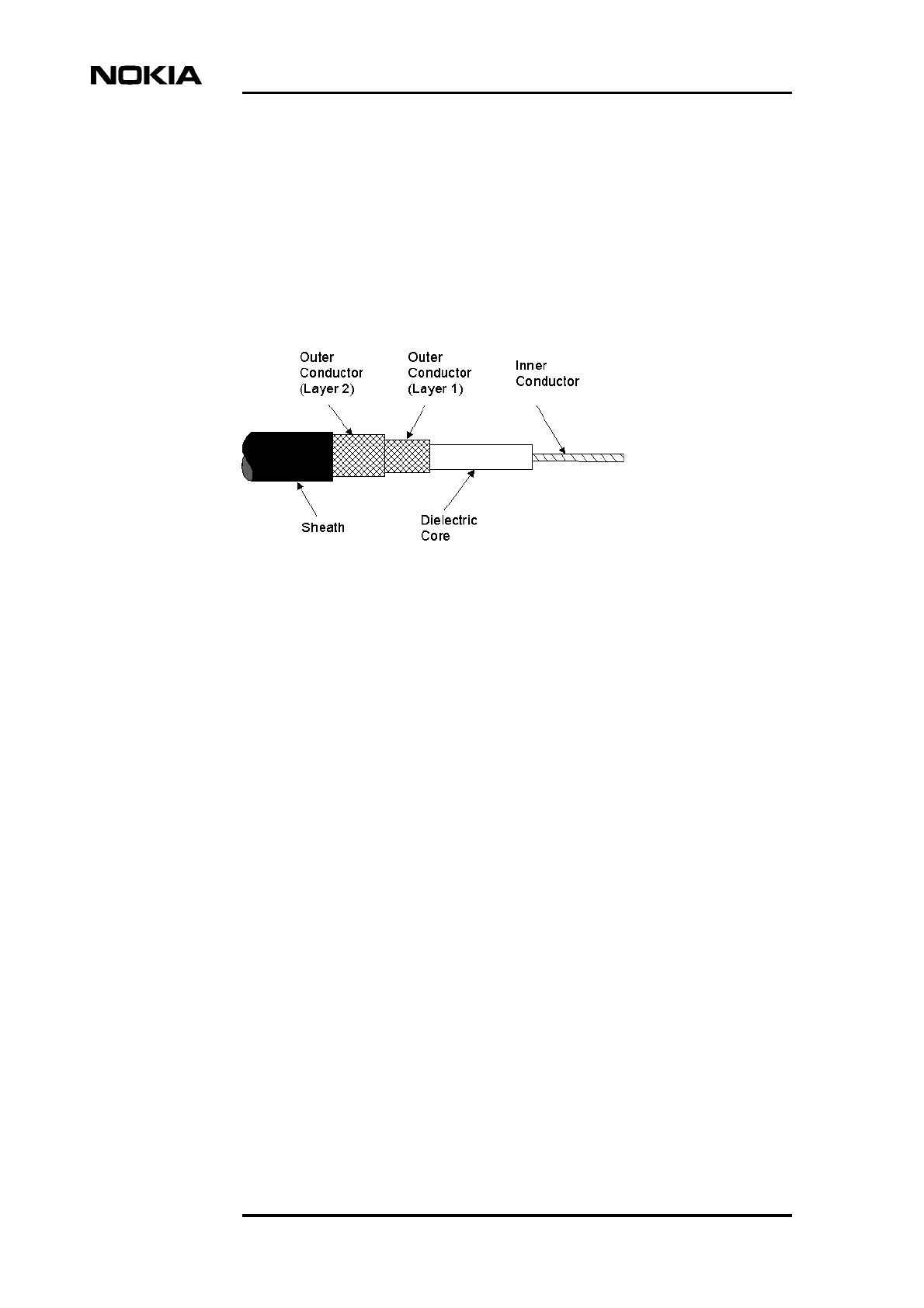
The cable is capable of handling frequencies up to 2.8 GHz and is, for example,
used to connect the radio outdoor unit to the transmission unit.
Table 2 and Figure 1 identify the diameter of the cable attributes. The 'D' and 'E'
min-max ranges allow for the different connectors used.
Cables, type RG223, of 4 m, 8 m and 15 m lengths terminated with TNC male
straight connectors are available. The product code for each of these is identified
in Table 1.
Figure 1. Flexbus cable
Accessories and specifications
DN99252966 © Nokia Corporation Draft 17 (66)
Issue 3-0 en Nokia Proprietary and Confidential
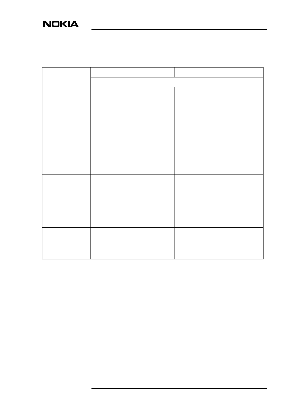
2.1.2 TNC male connector specifications (straight and right-angled)
Product code: T36630.01 and T36631.01 (RG214); T36627.01 and T36627.02
(RG223)
RF one step TNC connectors are single piece assemblies for the centre conductor
and the braid of a broad range of coaxial cables. The connectors are fully
compliant with MIL-C-39012 connectors. In this case, 50 Ω versions are used.
The features of these connectors include:
Table 2. Flexbus cable specifications
Parameter RG214 cable G223 cable
Detail
Inner Conductor 2.28 mm diameter
Silver plated copper wires (7)
5.6 Ω/km at 20oC
50+/- 2 Ω impedance
101 nf/km capacitance at 800 Hz
201 g/m weight
Attenuation: 23 dB/100 m at 800 MHz.
Specification: DIN 40500/T4
0.9 mm diameter
Silver plated copper wire (single)
29.4 Ω/km at 20oC
50+/- 2 Ω impedance
106 nf/km capacitance at 800 Hz
59 g/m weight
Attenuation: 69 dB/100 m at 1000 MHz
Specification: DIN 40500/T4
Dielectric Core 7.4 mm diameter
PE
Colour: neutral
3.05 mm diameter
PE
Colour: neutral
Outer conductor
(layer 1)
Braided shield, silver plated copper
wires
Specification: DIN 40500/T4
Braided shield, silver plated copper wires
Specification: DIN 40500/T4
Outer conductor
(layer 2)
9.1 mm diameter maximum
Braided shield, silver plated copper
wires
Specification: DIN 40500/T4
4.39 mm diameter maximum
Braided shield, copper plated wires
Specification: DIN 40500/T4
Sheath 10.9 mm diameter
PVC
Black
Specification: DIN 53505
5.55 -0.2 mm diameter
PVC
Black
Specification: DIN 53505

Solution Accessories
18 (66) © Nokia Corporation Draft DN99252966
Nokia Proprietary and Confidential Issue3-0en
• exceptional cable retention force to withstand vibration and frequent
connections and disconnections
• long term reliability
• usable with RG/U and Raychem Cheminax cables
• meets performance requirements of MIL-C-39012 up to 2.8 GHz
Only the right-angled connectors are used with type RG214 cable because of the
cable's rigidity.
Accessories and specifications
DN99252966 © Nokia Corporation Draft 19 (66)
Issue 3-0 en Nokia Proprietary and Confidential
Figure 2. TNC connectors
Solution Accessories
20 (66) © Nokia Corporation Draft DN99252966
Nokia Proprietary and Confidential Issue3-0en
Note
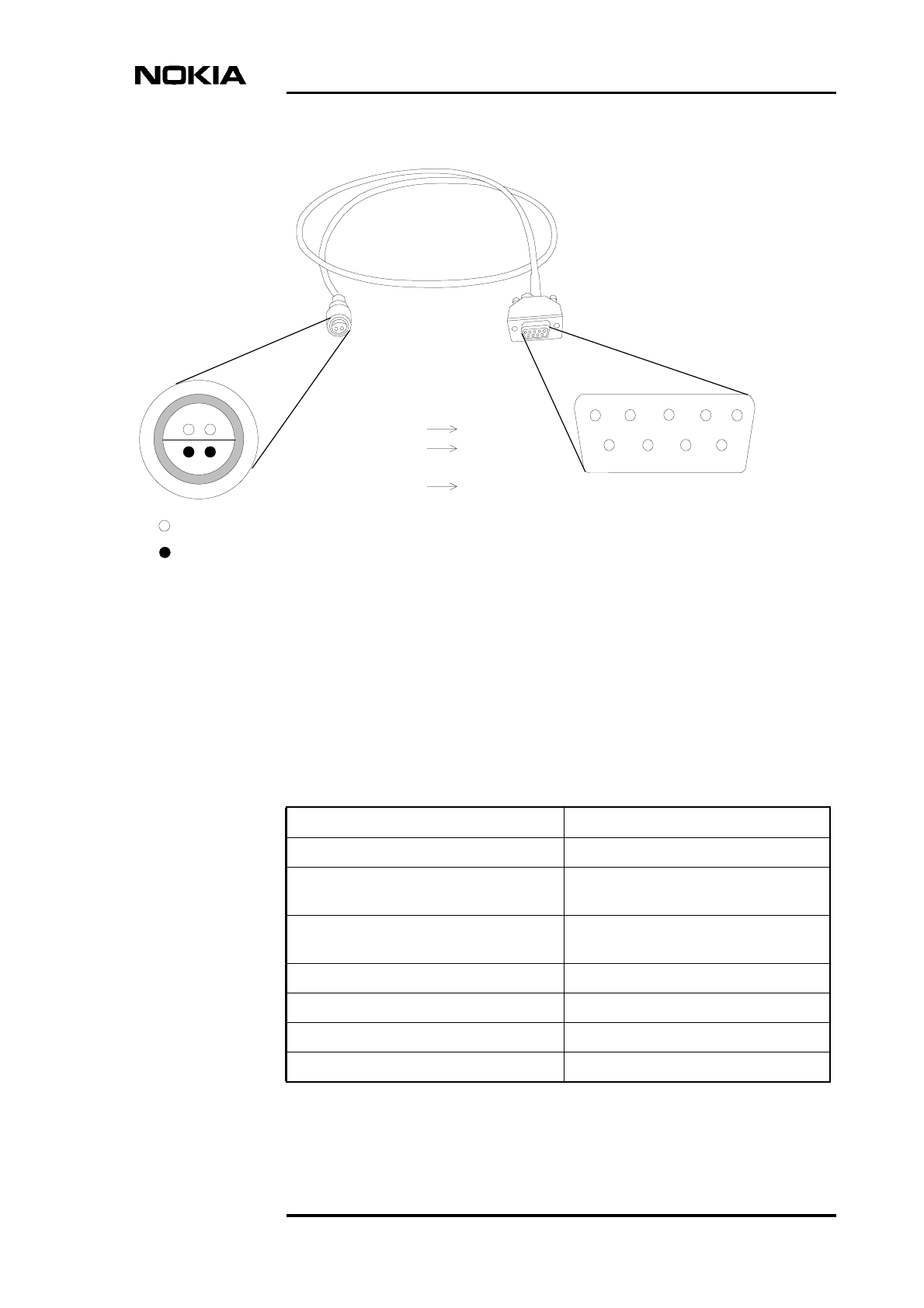
2.2 Local Management Port accessories
2.2.1 Q1 LMP cable specifications
Product code: T55270.01
This is an RS232 cable terminated with a BQ bayonet type connector at one end
and a 9-pin `D' type (D9F) connector at the other end. The length of the cable is
2,5 m and is provided already assembled.
RD = Received Data
TD = Transmitted Data
GND = Ground
n/c = not connected
The pins of each connector correlate as shown in Table 4. For example, pin 1 of
connector BQ connects to pin 3 of the ‘D’ type connector.
Table 3. LMP accessories for the MetroSite EDGE Base Station
Item Product code
Nokia Q1 LMP cable T55270.01
Table 4. LMP cable connector specifications
BQ Connector ‘D’ type Connector
Pin No. Function Pin No. Function
1 LMP in 3 TD
2 n/c 1, 4, 6-9 n/c
3 LMP out 2 RD
4 GND 5 GND
Accessories and specifications
DN99252966 © Nokia Corporation Draft 21 (66)
Issue 3-0 en Nokia Proprietary and Confidential
Figure 3. LMP cable and connectors
2.3 Abis PCM cable
43
2
1
43
2
15
9876
= Hole
= Pin
1 nc
2 RD
3 TD
4 nc
5 GND
6 nc
7 nc
8 nc
9 nc
3 LMP out
2 LMP in
4 GND
2 nc GND = Ground
RD = Received data
TD = Transmitted data
nc = not connected
BQ on the BTS end
of cable D9P (female) on the PC
end of cable
Table 5. Abis PCM cable and accessories
Item Product code
Abis PCM cable for MetroSite, 3 m, 120 ΩT36612.01
Abis PCM cable for MetroSite, 15 m, 120
Ω
T36612.05
Abis PCM cable for MetroSite, 50 m, 120
Ω
T36612.04
Abis PCM cable, 75 Ω/m T36602.01
Abis PCM cable, 120 Ω/m T36614.01
BT43 plug, 75 Ω, 6 pieces for ABC cable T36601.01
TQ plug, 120 Ω, 1 piece CS73214.02
Solution Accessories
22 (66) © Nokia Corporation Draft DN99252966
Nokia Proprietary and Confidential Issue3-0en
2.3.1 PCM cable 75 ohm
Product Code: T36602.01
The 75 Ω PCM cable is used for 2 Mbit transmission between the Nokia
MetroSite EDGE Base Station and a BSC. This high quality coaxial cable
consists of a plain copper inner conductor, polyethylene dielectric material, two
copper braids, and a PVC outer jacket.
2.3.2 PCM cable 120 ohm
Product Code: T36614.01
The 120 Ω PCM cable is used for 2 Mbit transmission between the Nokia
MetroSite EDGE Base Station and a BSC. This high quality cable consists of four
bare copper wires, polyethylene wire insulation, intermediate plastic tape
insulation, tinned copper wire gauze, and a halogen-free outer sheath.
The cables available are 3 m, 15 m, and 50 m, terminated with a TQ plug at each
end.
Table 6. PCM cable 75 Ω specifications
Characteristic impedance 75+ / - 4 Ω
Mutual capacitance 67 pF/m
Wave attenuation 1 MHz 2.3 dB/100 m
Wave attenuation 4 MHz 4.5 dB/100 m
Wave attenuation 20 MHz 9.2 dB/100 m
Operating voltage 300 V rms
Minimum bending radius 18 mm
Diameter 3.55 mm
Colour Black
Table 7. PCM cable 120 Ω specifications
Characteristic impedance 120+ / - 10 Ω
Mutual capacitance 40 nF/km
Wave attenuation 1 MHz 1.7 dB/100 m
Wave attenuation 4 MHz 3.5 dB/100 m
Accessories and specifications
DN99252966 © Nokia Corporation Draft 23 (66)
Issue 3-0 en Nokia Proprietary and Confidential
2.3.3 BT43 plug
Product code: T36601.01
This connector is used with the TZC5024 cable. For connection of this plug to the
Abis 75 Ω coaxial cable, refer to Attachment 1.
2.3.4 TQ plug
Product code: CS73214.02
This Abis 120 Ω interface connector supports the use of cables with outer
diameter of 4-13 mm and wires of dimension AWG 26-30.
For connection of this plug to the Abis 120 Ω cable refer to Attachment 2. The
cable is provided already assembled and is 2 m in length.
2.4 MetroSite antennas
Wave attenuation 20 MHz 7.8 dB/100 m
Operating voltage 300 V rms
Minimum bending radius 30 mm
Diameter 4.1 mm
Colour Grey
Table 7. PCM cable 120 Ω specifications (Continued)
Table 8. Antennas for the Nokia MetroSite EDGE Base Station
Item Product code
MetroSite 130o panel antenna, dual band
870-960 / 1710-1880 MHz, 5 dBi, 2 x N
female connectors
CS72454.01
MetroSite XX-pol panel antenna, dual
band 870-960 / 1710-1880 MHz, 65o,
12.5/13.5 dBi, 4 port
CS72180
MetroSite XX-pol panel antenna, dual
band 824-960 / 1710-2170 MHz, 65o,
14.5/17.5 dBi
CS72763.01
Solution Accessories
24 (66) © Nokia Corporation Draft DN99252966
Nokia Proprietary and Confidential Issue3-0en
2.4.1 MetroSite 130o panel antenna
Product code: CS72454.01
This antenna is a vertically polarised, dual band, two-port antenna providing 130o
coverage with a gain of 6 dBi.
MetroSite omni antenna, dual band 870-
960 / 1710-1880 MHz, 2 dBi, 2 x N female
connectors
CS72187
MetroSite omni antenna, dual band 824-
960 / 1805-2170 MHz, 2 dBi, N female
CS72187.02
Indoor omni antenna, multi-band 824-960
/ 1425-2170 MHz, 2 dBi, 360o, N female
CS72166
Indoor panel antenna, multi-band 824-960
/ 1425-2170 MHz, 7 dBi, 90o, N female
CS72168
Single pole mounting clamp for 50-115
mm poles
CS72196
Table 8. Antennas for the Nokia MetroSite EDGE Base Station (Continued)
Item Product code
Accessories and specifications
DN99252966 © Nokia Corporation Draft 25 (66)
Issue 3-0 en Nokia Proprietary and Confidential
Figure 4. MetroSite 130o panel antenna
Table 9. Specifications for the 130o antenna
Item GSM 900 GSM 1800
Frequency range 870-960 MHz 1710-1880 MHz
VSWR < 1:1.7 < 1:1.7
Gain 6 dBi 6 dBi
Impedance 50 Ω50 Ω
Polarization Vertical Vertical
Front-to-back ratio (co-
polar)
> 10 dB > 10 dB
Half power beam width Horizontal: 130o
Vertical: 55o
Horizontal: 130o
Vertical: 55o
Maximum power/input (at
25o C)
50 W 50 W
Solution Accessories
26 (66) © Nokia Corporation Draft DN99252966
Nokia Proprietary and Confidential Issue3-0en
Note
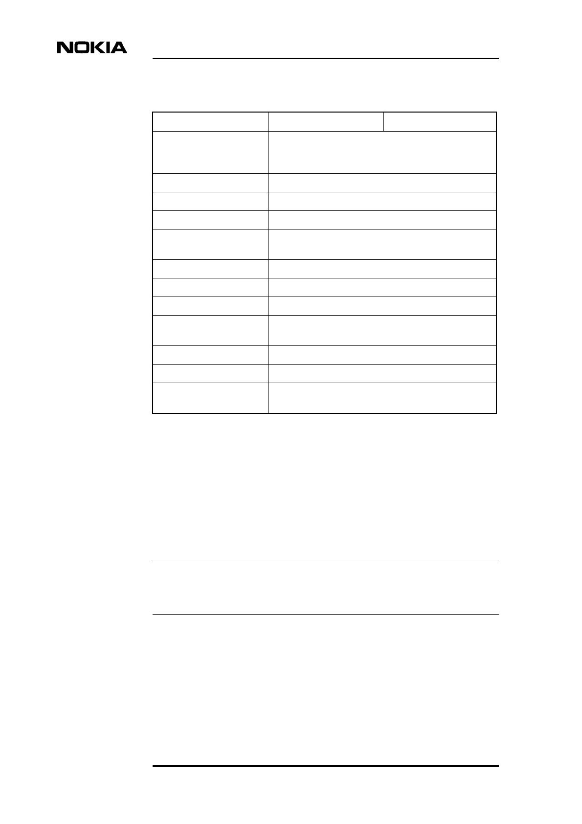
2.4.2 MetroSite XX-pol panel antenna
Product codes: CS72180, CS72763.01
This is a four port, dual band antenna. Its output is cross polarised + / - 45 o and
provides 65 o coverage with a gain of 12.5 to 13.5 dBi for the 900/1800 MHz
antenna and 14.5 to 17.5 dBi for the 850/1900 MHz antenna (see also the note
below).
Further variations of the Nokia MetroSite XX-pol panel 850/1900 MHz antennas
are available. Please contact your Nokia representative.
Isolation > 25 dB (GSM 900 - GSM 900) on Tx band > 30 dB
(GSM 1800 - GSM 1800) > 30 dB (GSM 900 - GSM
1800)
Input 2 x N female
Connector position Bottom
Weight 2.0 kg (without packaging)
Wind load Frontal: 27 N (at 150 km/h) Lateral: 16 N (at 150 km/h)
Rear side: 63 N (at 150 km/h)
Maximum wind velocity 150 km/h
Packing size 480 x 125 x 110 mm
Height x width x depth 452 x 95 x 100 mm
Material Reflector screen: painted aluminium Radome: ABS;
grey NCS S 2500-N screws and nuts: stainless steel
Mounting TBA
Ice protection The antenna remains operational during icy conditions
Grounding The metal parts of the antenna, including the mounting
kit are DC grounded.
Table 9. Specifications for the 130o antenna (Continued)
Item GSM 900 GSM 1800
Accessories and specifications
DN99252966 © Nokia Corporation Draft 27 (66)
Issue 3-0 en Nokia Proprietary and Confidential
900/1800 MHz XX-pol panel antenna (CS72180)
Figure 5. MetroSite XX-pol 900/1800 MHz panel antenna
Table 10. Specifications for the MetroSite XX-pol 900/1800 MHz panel
antenna
Item GSM 900 GSM 1800
Frequency range 870-960 MHz 1710-1880 MHz
VSWR < 1.5 < 1.5
Impedance 50 Ω50 Ω
Solution Accessories
28 (66) © Nokia Corporation Draft DN99252966
Nokia Proprietary and Confidential Issue3-0en
Polarization +45o ; -45o+45o ; -45o
Front-to-back ratio (co-
polar)
> 30 dB > 30 dB
Half power beam width +45o / -45o
Horizontal: 65o
Vertical: 28o
+45o / -45o
Horizontal: 65o
Vertical: 28o
Maximum power/input (at
50o C)
250 W 150 W
Isolation > 30 dB (GSM 900 - GSM 900) > 30 dB (GSM 1800 -
GSM 1800) > 30 dB (GSM 900 - GSM 1800)
Input 4 x 7-16 female
Connector position Top or bottom
Weight 7 kg
Wind load (at 150 km/h) Frontal: 110 N. Lateral: 60 N. Rearside: 240 N.
Maximum wind velocity 200 km/h
Packing size 782 x 287 x 165 mm
Height / width / depth 656 mm / 262 mm / 116 mm
Material Reflector screen: weather proof aluminium Radome:
fibreglass (white)
Screws and nuts: stainless steel
Mounting Walls: using two mounting plates already attached to
the antenna
Masts: using two clamps suitable for the mast diameter
Ice protection The antenna remains operational under icy conditions
Grounding The metal parts of the antenna, including the mounting
kit and the inner conductors are DC grounded.
Table 10. Specifications for the MetroSite XX-pol 900/1800 MHz panel
antenna (Continued)
Item GSM 900 GSM 1800
Accessories and specifications
DN99252966 © Nokia Corporation Draft 29 (66)
Issue 3-0 en Nokia Proprietary and Confidential
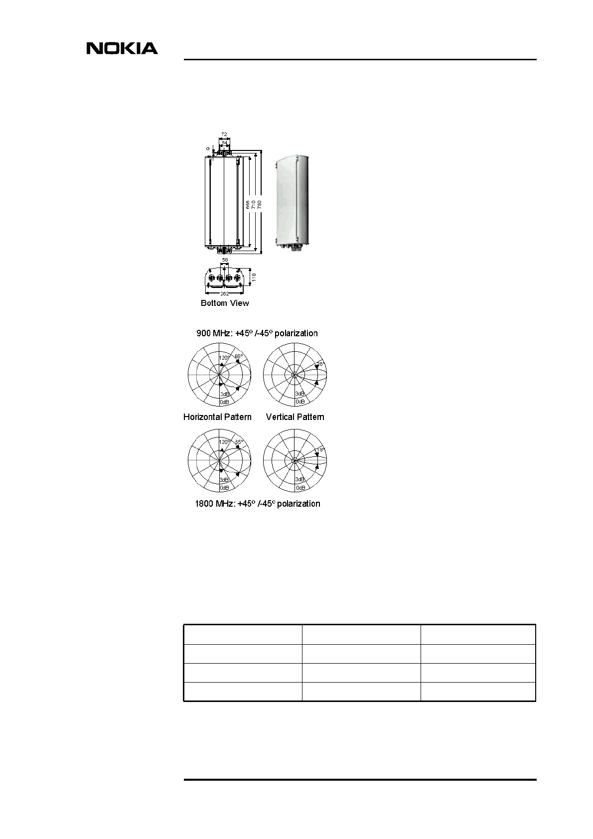
850/1900 MHz XX-pol panel antenna (CS72763.01)
Figure 6. MetroSite XX-pol 850/1900 MHz panel antenna
Solution Accessories
30 (66) © Nokia Corporation Draft DN99252966
Nokia Proprietary and Confidential Issue3-0en
Table 11. Specifications for the MetroSite XX-pol 850/1900 MHz panel
antenna
Item GSM 850 GSM 1900
Frequency range 824-960 MHz 1710-2170 MHz
VSWR < 1.5 < 1.5
Impedance 50 Ω50 Ω
Polarization +45o ; -45o+45o ; -45o
Front-to-back ratio (co-
polar)
> 28 dB > 25 dB
Half power beam width +45o / -45o
Horizontal: 68 - 65o
Vertical: 16 - 14.5o
+45o / -45o
Horizontal: 65 - 63o
Vertical: 7.5 - 6.5o
Maximum power/input (at
50o C)
250 W 200 W
Isolation: intrasystem > 30 dB
Isolation: intersystem > 45 dB
Input 4 x 7-16 female
Connector position Top or bottom
Weight 16.5 kg
Wind load (at 150 km/h) Frontal: 230 N. Lateral: 180 N. Rearside: 430 N.
Maximum wind velocity 200 km/h
Packing size 1590 x 287 x 177 mm
Height / width / depth 1296 mm / 262 mm / 139 mm
Material Reflector screen: weather proof aluminium Radome:
fibreglass (white)
Screws and nuts: stainless steel
Mounting Walls: using two mounting plates already attached to
the antenna
Masts: using two clamps suitable for the mast diameter
Ice protection The antenna remains operational under icy conditions
Grounding The metal parts of the antenna, including the mounting
kit and the inner conductors are DC grounded. The
inputs 824-960 MHz are also DC grounded. The inputs
1710-2170 MHz are coupled capacitively.
Accessories and specifications
DN99252966 © Nokia Corporation Draft 31 (66)
Issue 3-0 en Nokia Proprietary and Confidential
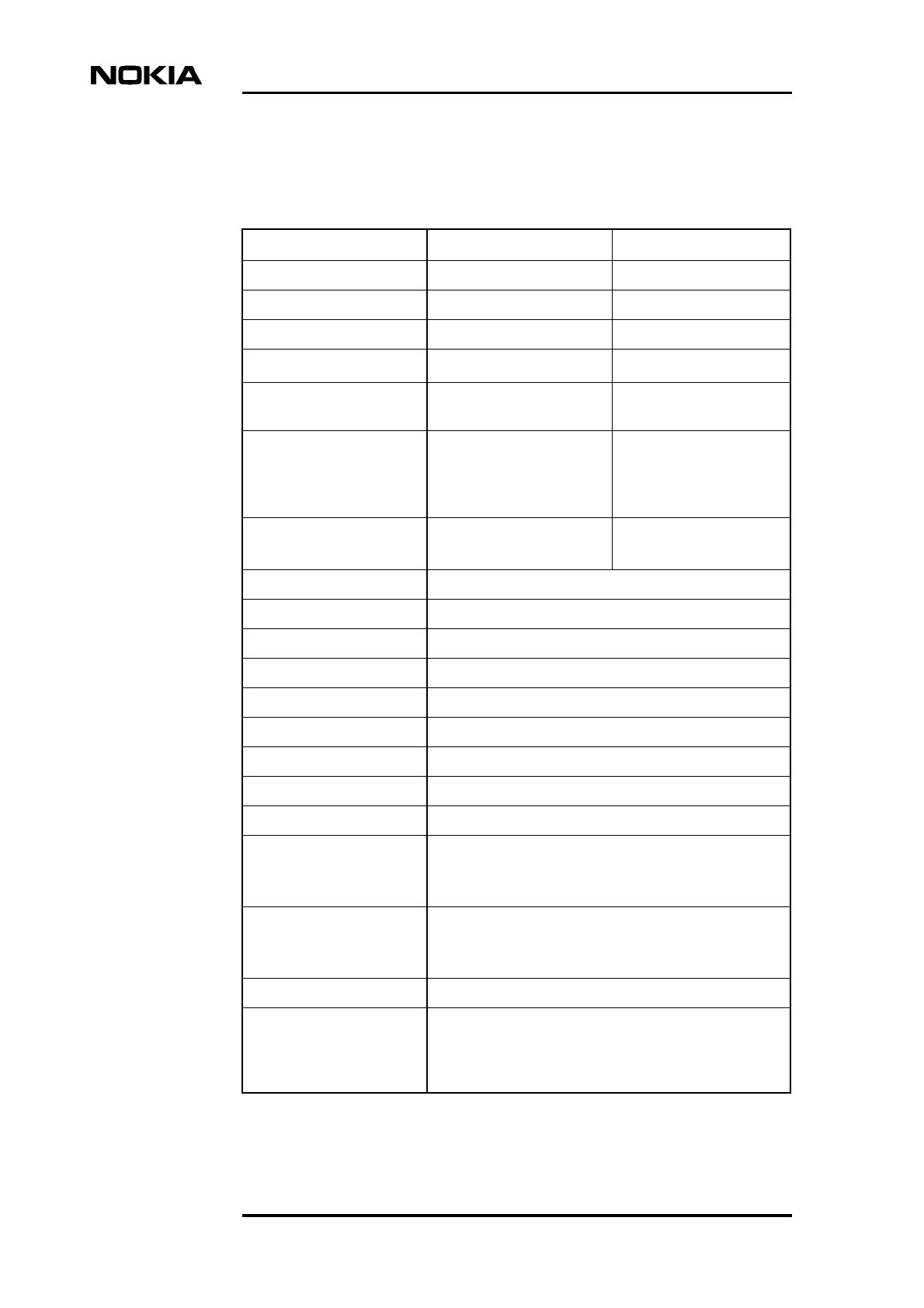
2.4.3 Omni dual band antenna
Product codes: CS72187, CS72187.02
This is a dual port, dual band 900/1800 or 850/1900 MHz antenna. The output is
omni-directional (360o) with a gain of 2 dBi and has two units (upper and lower).
900/1800 MHz omni-directional, dual band antenna (CS72187)
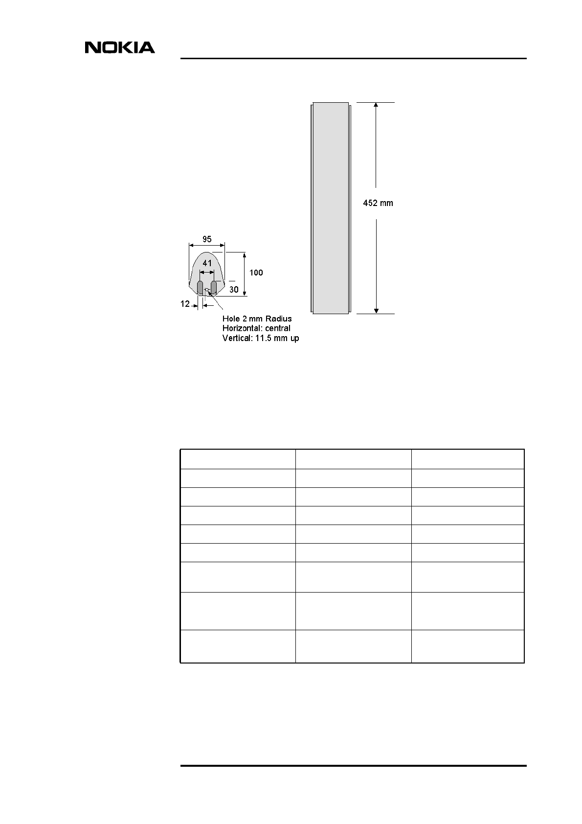
Figure 7. Omni-directional dual band 900/1800 MHz antenna
Table 12. Specifications for the omni-directional 900/1800 MHz dual band
antenna
Input 2 x N female
Frequency range 870-960 MHz and 1710-1880 MHz for the upper
and lower units
VSWR < 1.8
Gain 2 dBi
Impedance 50 Ω
Solution Accessories
32 (66) © Nokia Corporation Draft DN99252966
Nokia Proprietary and Confidential Issue3-0en
Polarization Vertical
Isolation > 25 dB
Maximum power/input 50 W at 50oC ambient temperature
Weight 1.2 kg
Radome diameter 30 mm
Wind load 30 N at 150 km/h
Maximum wind load 200 km/h
Packing size 700 x 80 x 80 mm (approximately)
Height 500 mm
Material Radiator: copper, brass
Radome: fibreglass (grey)
Base: weatherproof aluminium
Mounting clamp and screws: stainless steel
Mounting Attached laterally at the tip of a tubular mast of
40-70 mm diameter. The connecting cable (not
supplied) runs outside the mast.
Range of application Urban areas, preferably in places around
buildings at low or medium heights above ground
level or light poles or short masts on rooftops.
The antenna shape reduces the optical impact.
Grounding All metal parts of the antenna and the mounting
kit (excluding the inner conductor of the upper
unit) are DC grounded.
Table 12. Specifications for the omni-directional 900/1800 MHz dual band
antenna (Continued)
Accessories and specifications
DN99252966 © Nokia Corporation Draft 33 (66)
Issue 3-0 en Nokia Proprietary and Confidential
850/1900 MHz omni-directional, dual band antenna (CS72187.02)
Figure 8. Omni-directional dual band 850/1900 MHz antenna
Table 13. Specifications for the omni-directional 850/1900 MHz dual band
antenna
Input 2 x N female
Frequency range 824-960 MHz and 1805-2170 MHz for the upper
and lower units
VSWR < 2.0
Gain 2 dBi
Impedance 50 Ω
Polarization Vertical
Maximum power/input 50 W at 50oC ambient temperature
Weight 250 g
Radome diameter 20 mm
Solution Accessories
34 (66) © Nokia Corporation Draft DN99252966
Nokia Proprietary and Confidential Issue3-0en
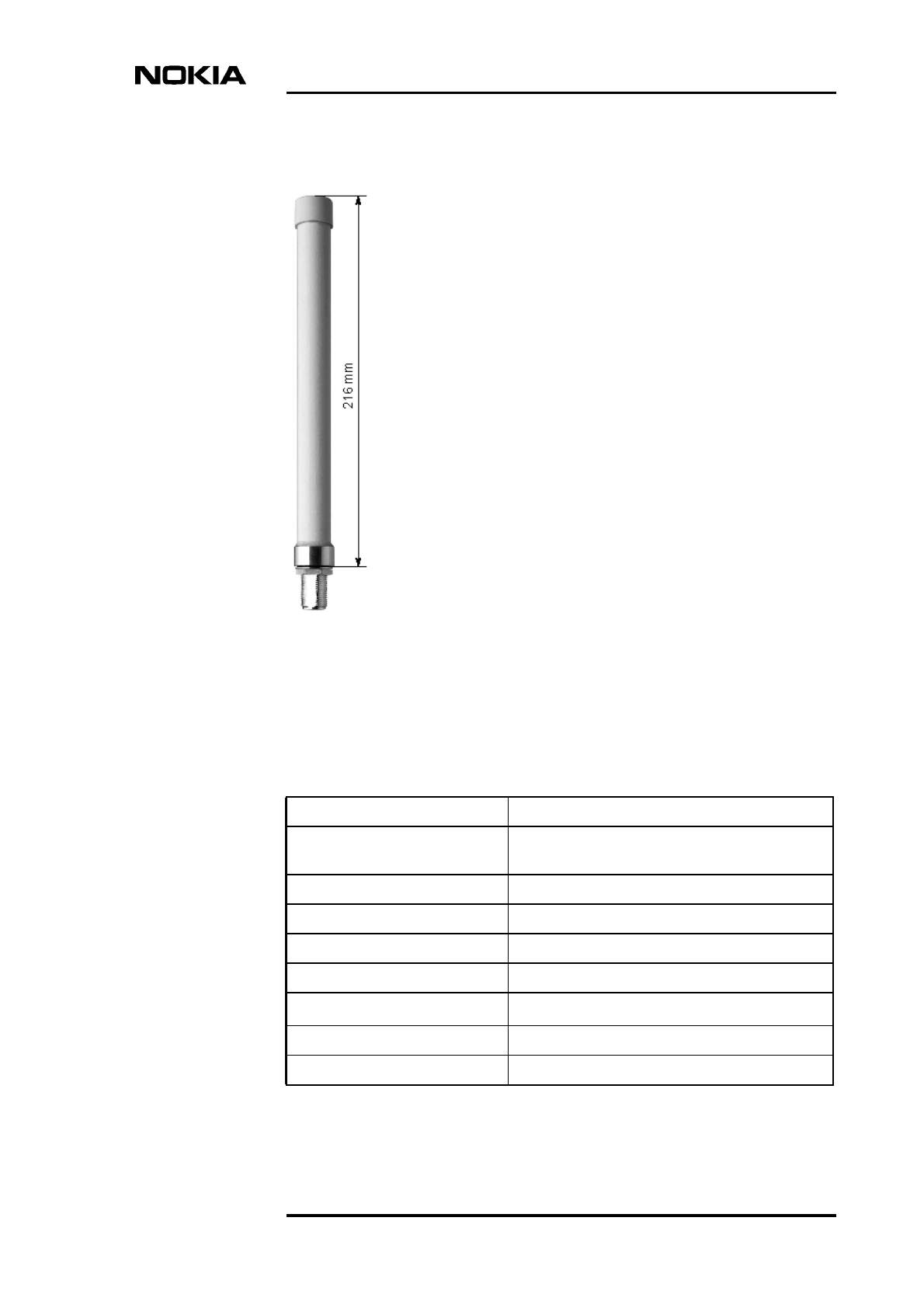
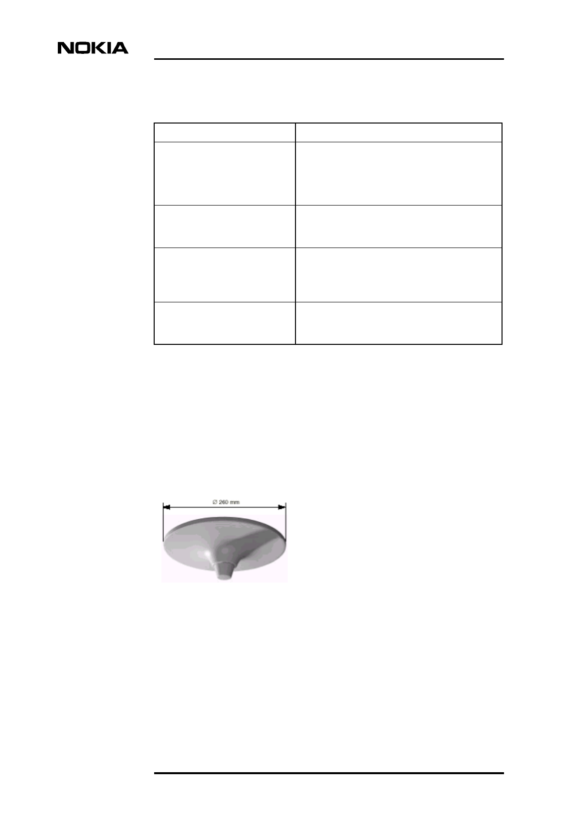
2.4.4 Indoor omni multi-band antenna
Product code: CS72166
This is a single port, multi-band 850/900/1800/1900 MHz antenna. This antenna
is vertically polarised and the horizontal radiation pattern is omni-directional
(360o) with a gain of 2 dBi. The antenna can be operated in all frequency ranges
simultaneously, and needs no additional groundplane.
Figure 9. Indoor omni multi-band antenna
Height 216 mm
Material Radiator: brass
Radome: fibreglass (white)
Base: weatherproof aluminium
Mounting clamp and screws: stainless steel
Mounting One hole mounting (16 mm) to surfaces of
maximum 10 mm thickness or attached laterally
at the tip of a tubular mast of 40-70 mm diameter.
Range of application Urban areas, preferably in places around
buildings at low or medium heights above ground
level or light poles or short masts on rooftops.
The antenna shape reduces the optical impact.
Grounding All metal parts of the antenna and the mounting
kit (excluding the inner conductor of the upper
unit) are DC grounded.
Table 13. Specifications for the omni-directional 850/1900 MHz dual band
antenna (Continued)
Accessories and specifications
DN99252966 © Nokia Corporation Draft 35 (66)
Issue 3-0 en Nokia Proprietary and Confidential
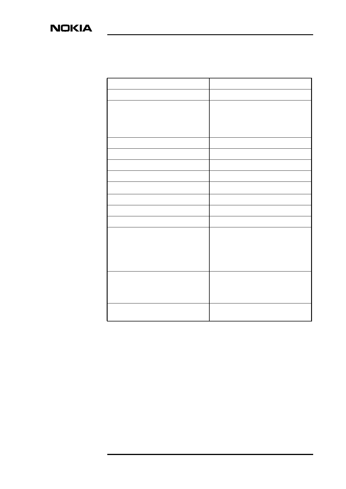
2.4.5 Indoor multi-band panel antenna
Product code: CS72168
This is a single port, multi-band indoor panel antenna. The antenna has a half
power beam width of 90 o with a gain of 7 dBi.
Table 14. Specifications for the indoor omni multi-band antenna
Input N female
Frequency range 824-960 MHz and 1425-2170 MHz
VSWR < 2.0: 824-960MHz
< 2.0: 1425-1710MHz
< 1.6: 1710-1990MHz
< 2.0: 1990-2170MHz
Gain 2 dBi
Input 1 x N female
Impedance 50 Ω
Polarization Vertical
Maximum power (at 50o C) 50 W /band
Weight 400 g
Diameter 260 mm
Height 78 mm (without connector)
Material Base: aluminium
Protective housing: high impact
polystyrol
Colour: white
Additional painting is possible
Mounting Three holes in the base to enable
mounting on a ceiling. Two types of
screws are supplied. N connector: a hole
of 35 mm diameter needed in the ceiling.
Grounding All metal parts including the inner
conductor are DC grounded.
Solution Accessories
36 (66) © Nokia Corporation Draft DN99252966
Nokia Proprietary and Confidential Issue3-0en
Figure 10. Indoor multi-band panel antenna
Table 15. Specifications for the indoor multi-band panel antenna
Input Cable RG 223/CU of 1 m length; white; N
female connector.
Frequency range 824-960 MHz and 1710-2170 MHz
VSWR 870-960 MHz and 1710-1900 MHz: < 1.6
824-960 MHz and 1710-2170 MHz: < 2.0
Gain 7 dBi approximately
Impedance 50 Ω
Polarization Vertical
Half power beam width Horizontal; 90o
Maximum power (at 50o C) 25 W
Weight 500 g
Packing size 321 x 165 x 50 mm
Height x width x depth 205 x 155 x 42 mm
Material Radiator: brass
Reflector: Aluminium
Radome: ABS (white)
Mounting plates: stainless steel
Mounting Two holes of 6 mm diameter in the
mounting plate.
Grounding All metal parts and inner conductor DC
grounded.
Accessories and specifications
DN99252966 © Nokia Corporation Draft 37 (66)
Issue 3-0 en Nokia Proprietary and Confidential
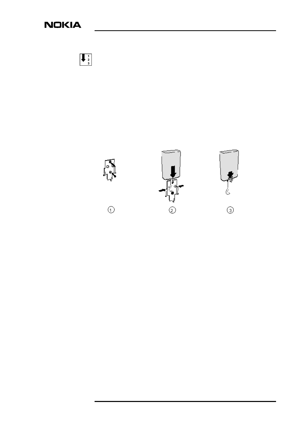
Installing the multi-band indoor panel antenna
1. Fix the attachment plate to the wall using two 4 mm diameter screws. See
[1] in Figure 11.
2. Align the antenna over the attachment plate, keeping the cable in the
middle of the plate. See [2] in Figure 11.
3. Pull the antenna downwards until it clicks into place. See [3] in Figure 11.
Do not pull the antenna downwards with the antenna cable.
Figure 11. Installing the indoor multi-band panel antenna
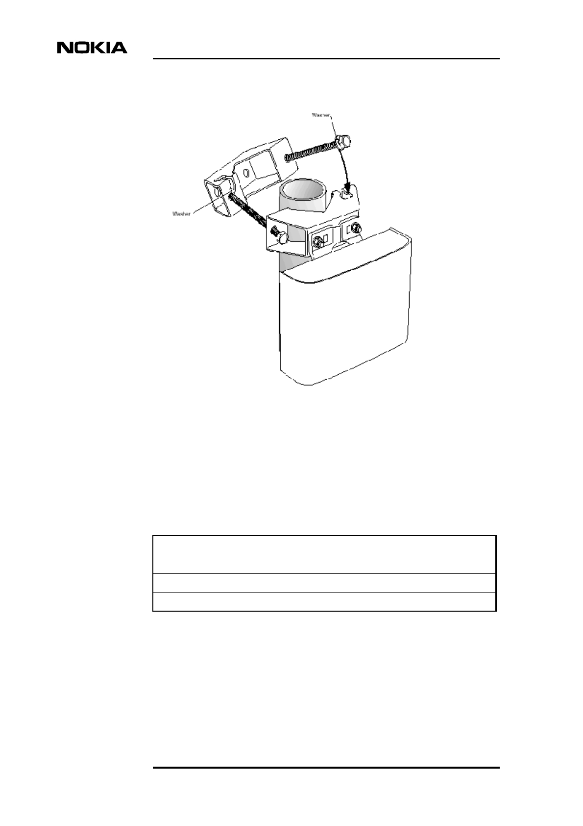
2.4.6 Pole mounting clamps (50-115 mm pole diameter)
Product code: CS72196
This standard single unit clamp is suitable for standard Nokia antennas.
The number of clamps required depends upon the antenna.
Solution Accessories
38 (66) © Nokia Corporation Draft DN99252966
Nokia Proprietary and Confidential Issue3-0en
Figure 12. Antenna pole mounting clamp
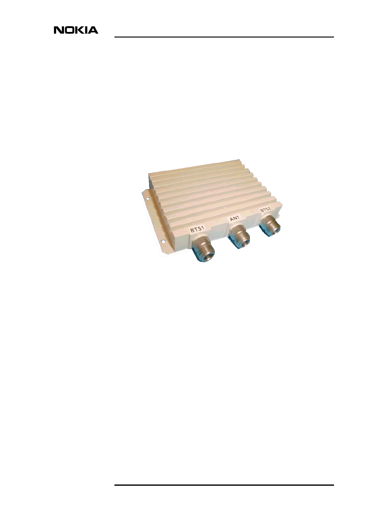
2.5 GSM/EDGE 900, 1800 and 1900 combiners
Product code: CS72216.01; CS72216.02; CS72216.03
The GSM/EDGE combiner is a cost-effective solution for combining two
MetroSite TRXs into a single antenna and feeder system.
Table 16. Combiners for the Nokia MetroSite EDGE Base Station
Item Product code
GSM/EDGE 900 BTS 2-to-1 combiner CS72216.01
GSM/EDGE 1800 BTS 2-to-1 combiner CS72216.02
GSM/EDGE 1900 BTS 2-to-1 combiner CS72216.03
Accessories and specifications
DN99252966 © Nokia Corporation Draft 39 (66)
Issue 3-0 en Nokia Proprietary and Confidential
The GSM/EDGE combiner allows you to combine the transmit signals from the
transceivers and also divide receive signals from the antenna to those
transceivers.
The GSM/EDGE 900, 1800 and 1900 combiners function in an identical manner
and are designed for mounting outdoors. The combiners are compact,
lightweight, easy to install, and require no maintenance.
Figure 13. GSM/EDGE combiner
Solution Accessories
40 (66) © Nokia Corporation Draft DN99252966
Nokia Proprietary and Confidential Issue3-0en
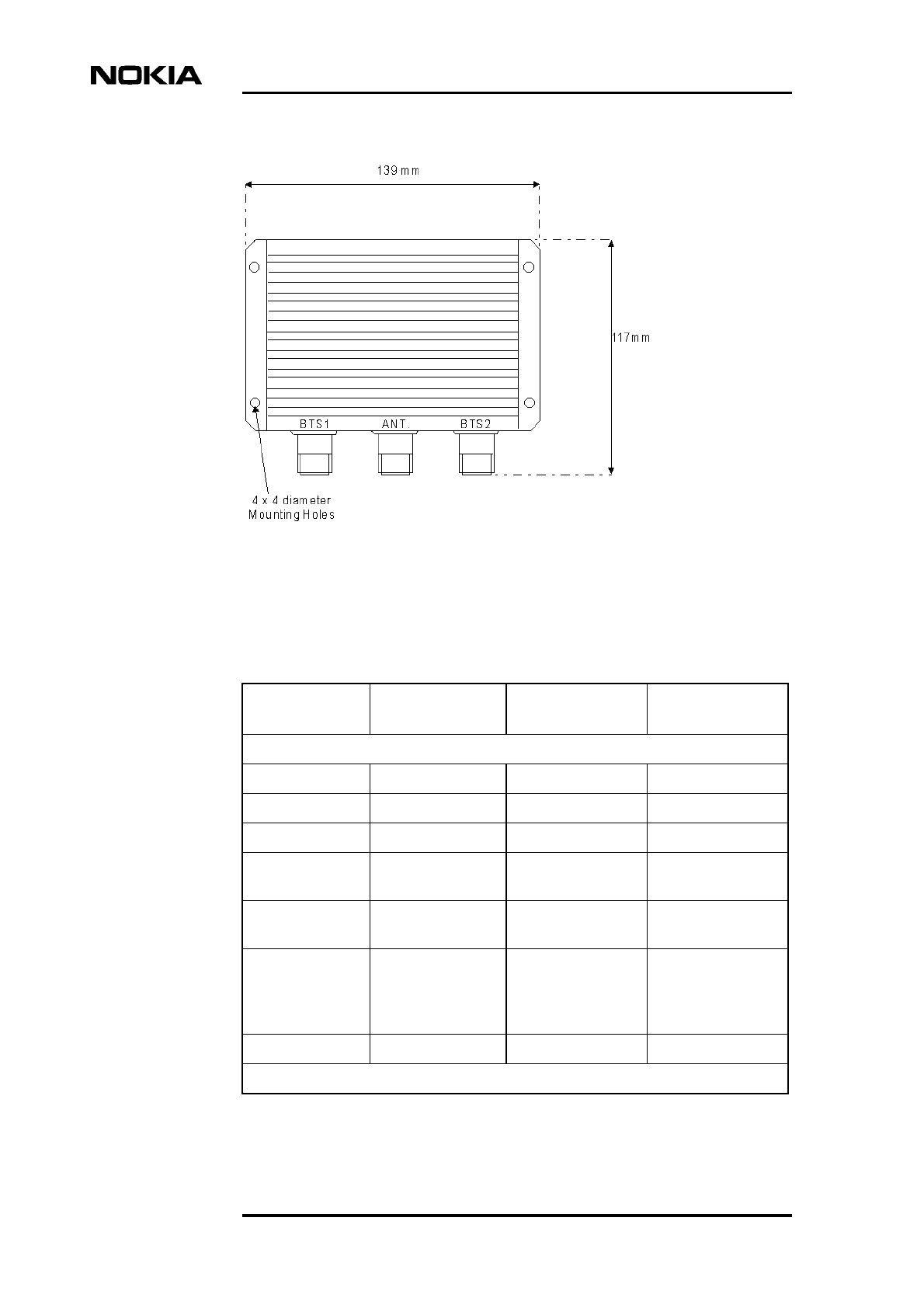
Figure 14. Dimensions of the GSM/EDGE combiner
Table 17. Specifications for the GSM/EDGE combiners
GSM 900
Combiner
GSM 1800
Combiner
GSM 1900
Combiner
Transmit Path:
Frequency range 925-960 MHz 1805-1880 MHz 1930-1990 MHz
Impedance 50 Ω50 Ω50 Ω
Insertion loss 3.5 dB maximum 3.5 dB maximum 3.5 dB maximum
Antenna port
return loss
18 dB minimum 18 dB minimum 18 dB minimum
BTS port return
loss
18 dB minimum 18 dB minimum 18 dB minimum
Isolation BTS
port to BTS port
(antenna port
loaded to 50 Ω
25 dB minimum 25 dB minimum 25 dB minimum
Power handling 2 x 10 W 2 x 10 W 2 x 10 W
Receive Path:
Accessories and specifications
DN99252966 © Nokia Corporation Draft 41 (66)
Issue 3-0 en Nokia Proprietary and Confidential
Frequency range 880-915 MHz 1710-1785 1850-1910
Impedance 50 Ω50 Ω50 Ω
Insertion loss 3.5 dB maximum 3.5 dB maximum 3.5 dB maximum
Antenna port
return loss
18 dB minimum 18 dB minimum 18 dB minimum
BTS port return
loss
18 dB maximum 18 dB maximum 18 dB maximum
Power division
imbalance
0.5 dB maximum 0.5 dB maximum 0.5 dB maximum
Intermodulation: 2 x 10 W unmodulated carriers:
Antenna port 880-915 MHz: -
100 dBm
maximum
1710-1785 MHz: -
100 dBm maximum
1850-1910 MHz: -
100 dBm maximum
BTS port 880-915 MHz: -
116 dBm
maximum
1710-1785 MHz: -
116 dBm maximum
1850-1910 MHz: -
116 dBm maximum
Outside the
bands indicated
-38 dBm maximum -38 dBm maximum -38 dBm maximum
Mechanical:
W x H x D mm 139 x 117
(including
connectors) x 27
mm
139 x 117
(including
connectors) x 27
mm
139 x 117
(including
connectors) x 27
mm
Weight 680 g 680 g 680 g
Connectors N type female
(silver plated)
N type female
(silver plated)
N type female
(silver plated)
Enclosure Aluminium; RAL
7047
Aluminium; RAL
7047
Aluminium; RAL
7047
Environmental:
Protection IP65 IP65 IP65
Operating
temperature -40oC to +60oC -40oC to +60oC -40oC to +60oC
Lightning
specification
IEC 1312-1 IEC 1312-1 IEC 1312-1
Table 17. Specifications for the GSM/EDGE combiners (Continued)
GSM 900
Combiner
GSM 1800
Combiner
GSM 1900
Combiner
Solution Accessories
42 (66) © Nokia Corporation Draft DN99252966
Nokia Proprietary and Confidential Issue3-0en
2.6 Antenna lines
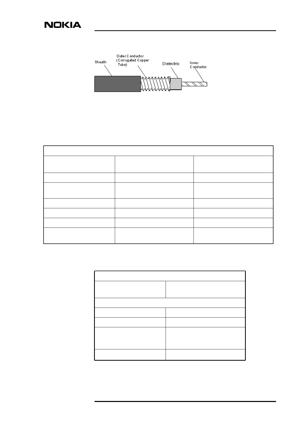
2.6.1 Antenna line cables
Product code: CS72259.10 and CS72258.10
The inner conductor is copper clad aluminium wire contained in a cellular
polyethylene dielectric. The outer conductor constitutes a corrugated copper tube.
The markings on the sheath consist of the manufacturer's name, cable type, week
of manufacture, year of manufacture, and cable length in metres.
Storage Class 1.3E ETSI
300 010-1-1
Class 1.3E ETSI
300 010-1-1
Class 1.3E ETSI
300 010-1-1
Transportation Class 2.3 ETSI
300 019-1-2
Class 2.3 ETSI 300
019-1-2
Class 2.3 ETSI 300
019-1-2
MTBF > 500,000 hours > 500,000 hours > 500,000 hours
Table 17. Specifications for the GSM/EDGE combiners (Continued)
GSM 900
Combiner
GSM 1800
Combiner
GSM 1900
Combiner
Table 18. Antenna line accessories for the Nokia MetroSite EDGE Base
Station
Item Product code
N-male 3/8" straight connector CS72683.20
N-male 3/8" angle connector CS72683.21
7-16 male, 3/8” connector for superflex
cable
CS72697
3/8" cable, RFF-50, telegrey, 250 m reel,
superflex, UV
CS72259.10
3/8" cable, RFF-50, black, 250 m reel,
superflex, UV
CS72258.10
Accessories and specifications
DN99252966 © Nokia Corporation Draft 43 (66)
Issue 3-0 en Nokia Proprietary and Confidential
Figure 15. Antenna line cable
Table 19. Sheath characteristics for the antenna line cable
Sheath Characteristics
Item 3/8"-50 LD GY7047
(CS72259.10)
3/8"-50 (CS72258.10)
Jacket Telegrey, LD polyethylene Black, LD polyethylene
IEC754-1/-2 (halogen free, non-
corrosive
Yes Ye s
IEC1034 (low smoke emission) No No
IEC332-3C (fire retardant) No No
UV retardant Yes Yes
Minimum installation
temperature -20o C -20o C
Table 20. Cable characteristics for the antenna line cable
Cable Characteristics
Item CS72258.10 and CS72259.10
(3/8")
Mechanical:
Weight 130 kg/km
Maximum pulling force 400 N
Minimum bending radius: -
single bending - repeated
bending
13 mm; 25 mm
Operating temperature range -40o C to +70o C
Solution Accessories
44 (66) © Nokia Corporation Draft DN99252966
Nokia Proprietary and Confidential Issue3-0en
Electrical at +20o C
Characteristic impedance 50 + 1 Ω
Attenuation See table
Velocity factor 0.81
Capacitance 82 pF/m
Cut-off frequency 15200 MHz
Maximum operating frequency 3000 MHz
Maximum power rating See table
Peak RF voltage rating 1.04 kV
Peak power rating 11 kW
DC resistance: inner conductor 5.1 Ω/km
DC resistance: outer conductor 6.1 Ω/m
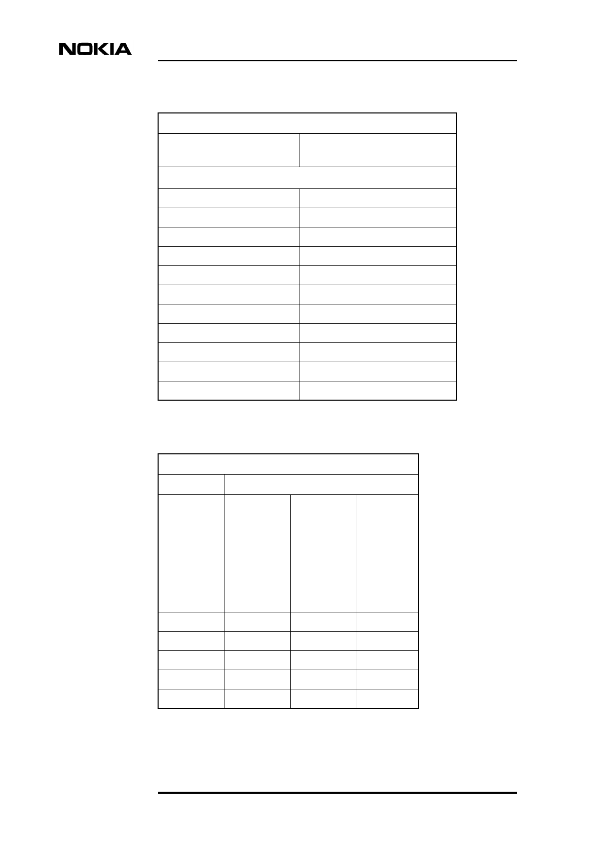
Table 21. Attenuation and power characteristics for the antenna line cable
Attenuation (maximum) and power rating
CS72258.10 and CS72259.10 (3/8”)
Frequency
(MHz)
Attenuatio
n at
ambient
temp. 20o
C dB/100
m
Power
rating at
ambient
temp.40oC
inner
conductor
+70o C
(kW)
Power
rating at
ambient
temp.40o
C inner
conducto
r +100o C
(kW)
700 12.1 0.32 0.69
800 13.0 0.30 0.64
850 13.4 0.29 0.62
900 13.9 0.29 0.60
950 14.3 0.28 0.58
Table 20. Cable characteristics for the antenna line cable (Continued)
Cable Characteristics
Item CS72258.10 and CS72259.10
(3/8")
Accessories and specifications
DN99252966 © Nokia Corporation Draft 45 (66)
Issue 3-0 en Nokia Proprietary and Confidential
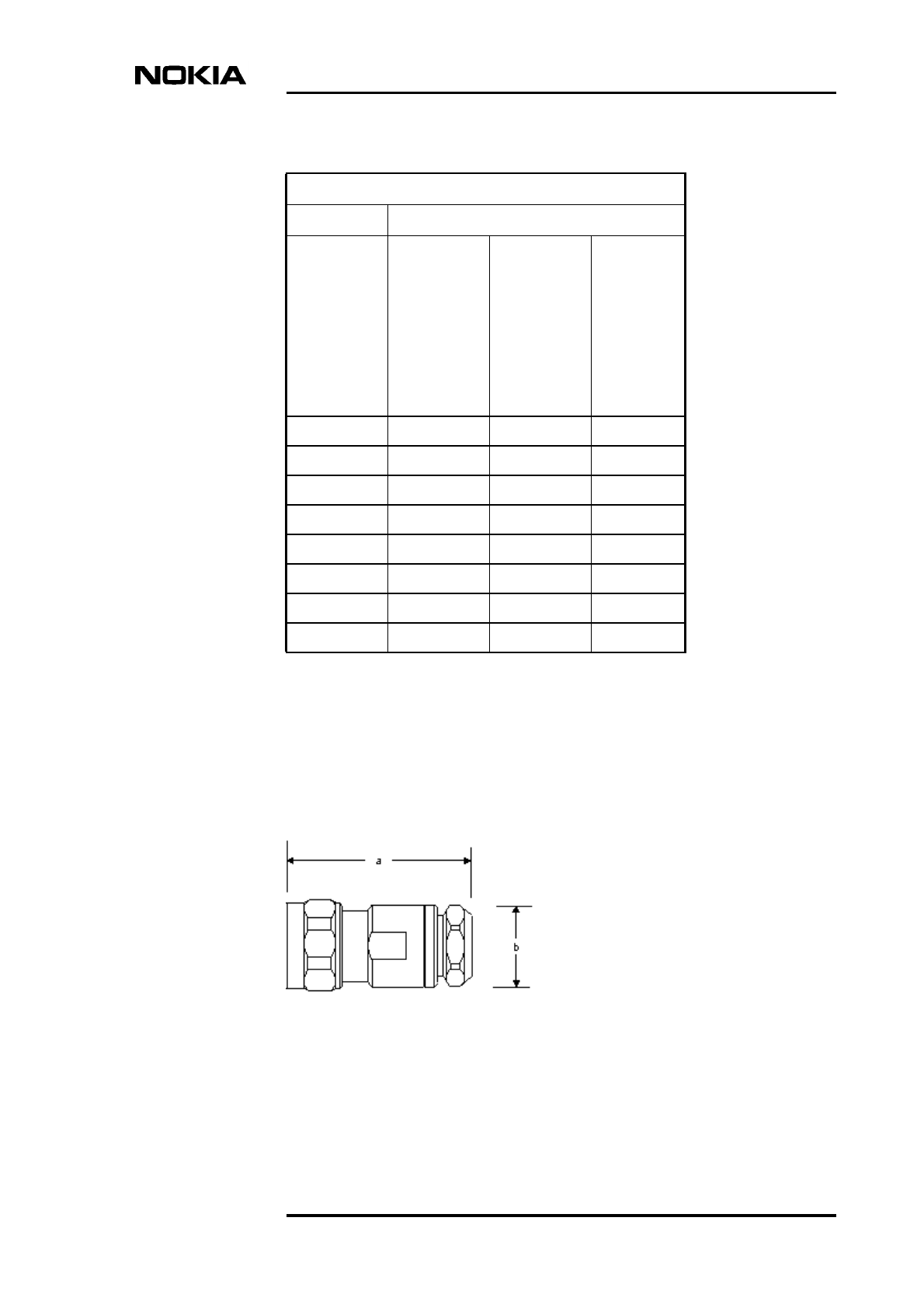
2.6.2 N male connector: straight
Product code: CS72683.20 (3/8")
This connector type is suitable for 3/8 inch helical cable and facilitates solderless
attachment of the inner wire of the connected cable.
Figure 16. N male connector
1000 14.7 0.26 0.57
1200 16.3 0.24 0.51
1400 17.8 0.22 0.47
1600 19.1 0.20 0.44
1800 20.5 0.19 0.41
1900 21.1 0.18 0.40
2000 21.8 0.18 0.39
2200 23.0 0.17 0.37
Table 21. Attenuation and power characteristics for the antenna line cable
Attenuation (maximum) and power rating
CS72258.10 and CS72259.10 (3/8”)
Frequency
(MHz)
Attenuatio
n at
ambient
temp. 20o
C dB/100
m
Power
rating at
ambient
temp.40oC
inner
conductor
+70o C
(kW)
Power
rating at
ambient
temp.40o
C inner
conducto
r +100o C
(kW)
Solution Accessories
46 (66) © Nokia Corporation Draft DN99252966
Nokia Proprietary and Confidential Issue3-0en
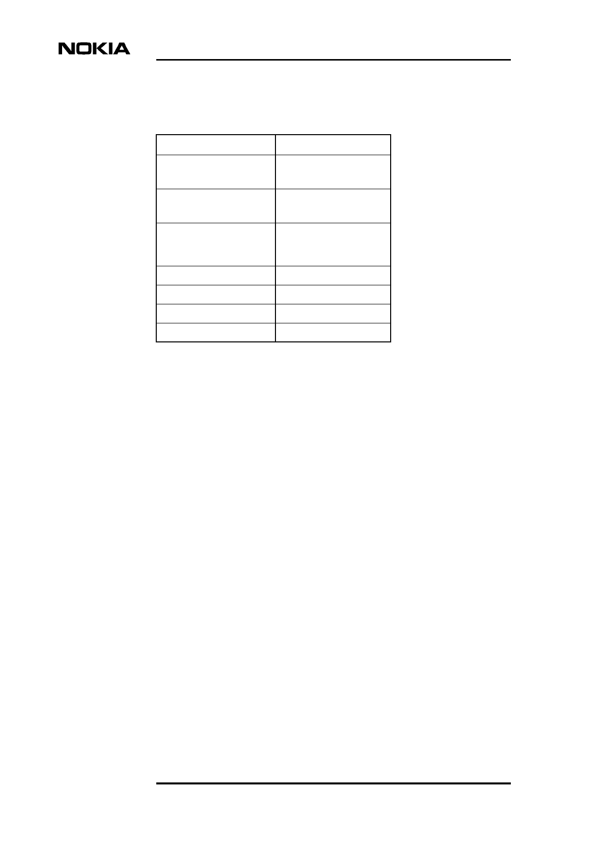
2.6.3 N male connector: right angled
Product code: CS72683.21 (3/8")
This connector type is suitable for 3/8" helical cable and facilitates solderless
attachment of the inner wire of the connected cable.
Table 22. Specifications for the N male connector
Item CS72683.20 (3/8")
Frequency f/GHz 0 < f ≤ 1
1 < f ≤ 2.7
VSWR ≤ 1.02
≤ 1.03
Intermodulation (2x20W;
936/958MHz; 1770/1810
MHz)
≤ -155 dBc
Assembly time < 2 minutes
Weight 70 g
a (mm) 47
b (mm) 21
Accessories and specifications
DN99252966 © Nokia Corporation Draft 47 (66)
Issue 3-0 en Nokia Proprietary and Confidential
Figure 17. N male connector, right angled
Table 23. Specifications for the N male connector, right angled
Item CS72683.21 (3/8")
Frequency f/GHz 0< f ≤1
1 < f ≤2
2 < f ≤ 2.7
2.7 < f ≤ 3.7
VSWR ≤ 1.02
≤ 1.04
≤ 1.06
≤ 1.13
Intermodulation (2x20W;
936/958MHz; 1770/1810
MHz)
≤ -155 dBc
Assembly time < 2 minutes
Weight 145 g
Solution Accessories
48 (66) © Nokia Corporation Draft DN99252966
Nokia Proprietary and Confidential Issue3-0en
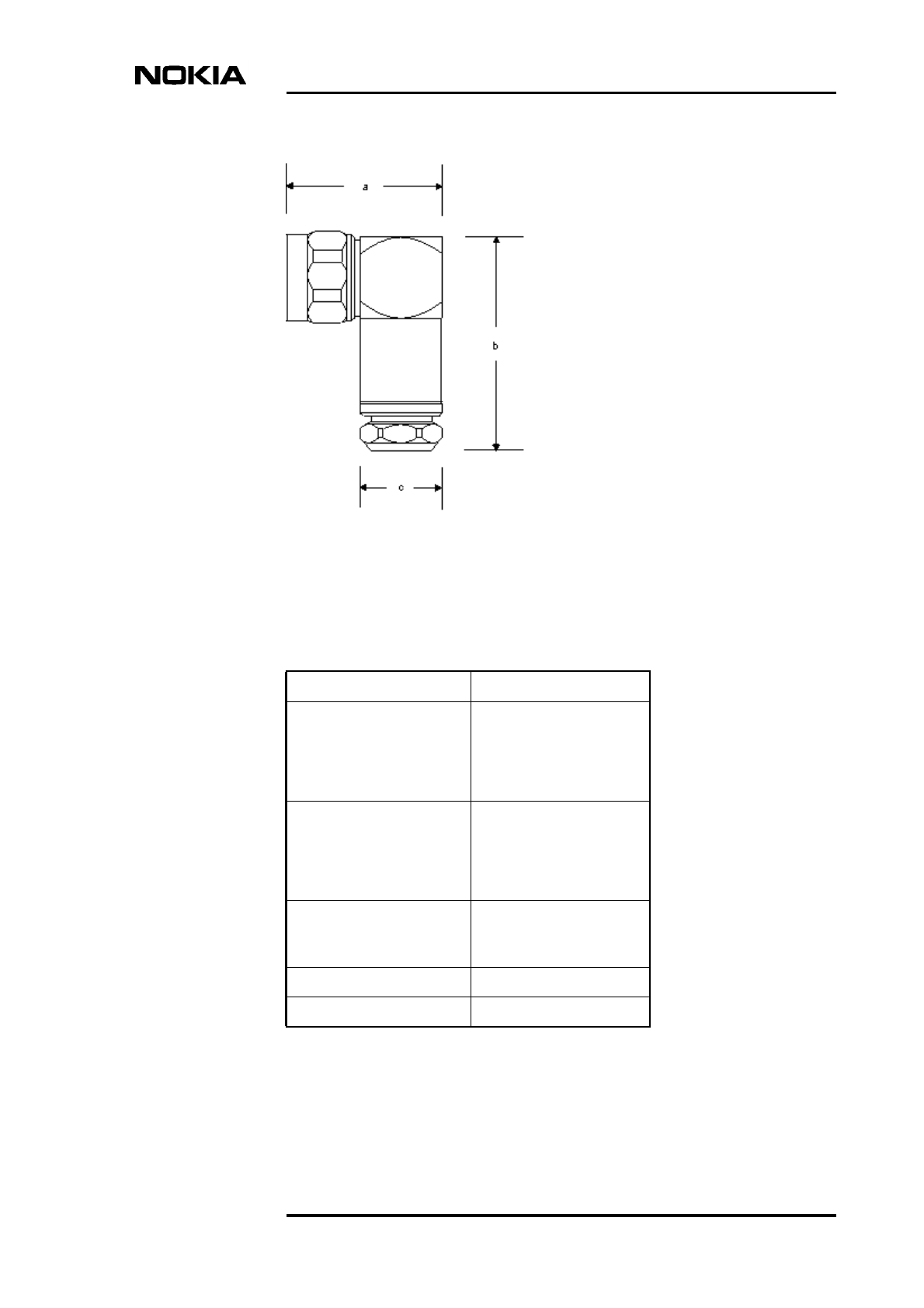
2.6.4 7-16 Straight Male connector
Product code: CS72697 (3/8")
This connector type is suitable for 3/8" helical cable and facilitates solderless
attachment of the inner wire of the connected cable.
Figure 18. 7-16 Straight male connector
a (mm) 36
b (mm) 38.3
c (mm) 23
Table 23. Specifications for the N male connector, right angled (Continued)
Item CS72683.21 (3/8")
Table 24. Specifications for the N male connector, right angled
Item CS72697 (3/8")
Frequency f/GHz 0 < f ≤ 1
1 < f ≤ 2.7
2.7 < f ≤ 3.7
VSWR ≤ 1.02
≤ 1.03
≤ 1.06
Intermodulation (2x20W;
936/958MHz; 1770/1810
MHz)
≤ -155 dBc
Accessories and specifications
DN99252966 © Nokia Corporation Draft 49 (66)
Issue 3-0 en Nokia Proprietary and Confidential
Note
2.7 MetroSite Battery Backup Unit
Product code: CS70401.01 for BBU (without batteries) and .02 for batteries
2.7.1 Battery Backup Unit
The MetroSite BBU is designed to provide 110 VAC or 230 VAC backup support
for connected elements.
The MetroSite BBU is able to support a single MetroSite BTS or a single
MetroHub and can be pole or wall mounted in almost any location, indoors or
outdoors. Its appearance is identical to the MetroSite BTS and the MetroHub,
consequently it can be readily integrated into a site location unobtrusively.
2.7.2 Mains power cable (230 VAC)
This item is included in CS70401.01.
The 230 VAC power cables for AC connectivity are light and flexible. They can
be installed in dry, damp and wet environments, both indoor and outdoor, in
addition to fire-sensitive locations.
The cable has three conductors made of high quality copper insulated with
EPDM-rubber.
Assembly time < 2 minutes
Weight 105 g
a (mm) 39
b (mm) 21
Table 24. Specifications for the N male connector, right angled (Continued)
Item CS72697 (3/8")
Solution Accessories
50 (66) © Nokia Corporation Draft DN99252966
Nokia Proprietary and Confidential Issue3-0en
Note
Note
One end of the cable is fitted with an IEC320 female connector and the other end
with an appropriate three-pin male connector for connection to the mains power
source (user defined).
The MetroSite BTS or MetroHub mains power cable can be utilised for
connecting the MetroSite BBU to the mains power source.
2.7.3 230/110 VAC output cable
This item is included in CS70401.01.
The 230/110 VAC power cables for AC connectivity are light and flexible. They
can be installed in dry, damp and wet environments, both indoor and outdoor, in
addition to fire-sensitive locations.
The cable has three conductors made of high quality tinned copper insulated with
EPDM-rubber and is 2 metres in length.
Table 25. Specifications for the 230 VAC mains power cable
Code Detail
Cross section 1.5 mm2
Nominal diameter 9.0 mm
Nominal voltage Uo /U 300 V/500 V
Maximum continuous operating
temperature +60o C
Minimum recommended handling
temperature -50o C
Minimum bending radius 54 mm
Live wire colour Brown
Neutral wire colour Blue
Earthing cable colour Green/yellow
Sheath colour Black
Accessories and specifications
DN99252966 © Nokia Corporation Draft 51 (66)
Issue 3-0 en Nokia Proprietary and Confidential
Note
One end of the cable is fitted with an IEC320 female connector and the other end
with an IEC320 male connector. The former connects to the MetroSite BBU and
the latter to a MetroSite BTS or MetroHub.
2.7.4 Alarm cable
This item is included in CS70401.01.
This cable facilitates the monitoring of the status of the various MetroSite BBU
alarm outputs at a remote control centre via the MetroSite BTS.
The cable is fitted with an X3, mini D26 (EAC) connector at each end.
Table 26. Specifications for the 230/110 VAC mains power cable
Code Detail
Cross section 1.5 mm2
Nominal diameter 9.0 mm
Nominal voltage Uo /U 300 V/500 V
Maximum continuous operating
temperature +60o C
Minimum recommended handling
temperature -50o C
Minimum bending radius 54 mm
Live wire colour Brown
Neutral wire colour Blue
Earthing cable colour Green-yellow
Sheath colour Black
Solution Accessories
52 (66) © Nokia Corporation Draft DN99252966
Nokia Proprietary and Confidential Issue3-0en
Note
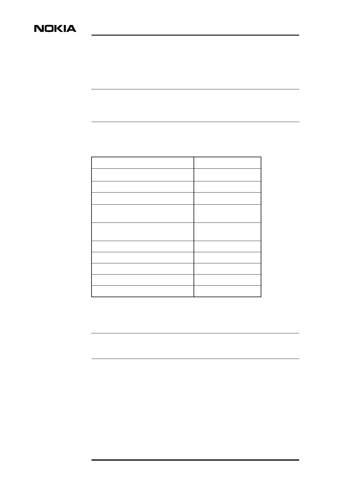
2.7.5 Battery connection kit
This item is included in CS70401.01.
The kit provides the connection busbars and the connector cable for the battery
backup to the MetroSite BBU. The cable which connects the batteries to the
MetroSite BBU is fitted with terminals for connection to the batteries and a
common connector for connection to the MetroSite BBU -48 VDC connector.
Table 27. Specifications for the alarm cable
Pin Signal Pin Signal
1 EAC1 14 GND
2 EAC2 15 GND
3 EAC3 16 GND
4 EAC4 17 GND
5 EAC5 18 GND
6 EAC6 19 GND
7 EAC7 20 GND
8 EAC8 21 GND
9 EAC9 22 GND
10 EAC10 23 GND
11 CO1 24 CO3
12 +3 V 25 CO4
13 CO2 26 +5 V
Table 28. Contents of the battery connection kit
Item Quantity
10-pin genderless connection cable 1
Short battery inter-connecting busbar 2
Long battery inter-connecting busbar 1
Accessories and specifications
DN99252966 © Nokia Corporation Draft 53 (66)
Issue 3-0 en Nokia Proprietary and Confidential
Figure 19. Battery connection kit
2.8 Miscellaneous
Table 29. Miscellaneous accessories for the Nokia MetroSite EDGE Base
Station
Item Product code
Earthing cable, 16 mm2CS73174
Metro Hopper optical alignment tool T55875.01
Alarm cable (between BTS and Hub) CS72451.20
Pole mounting kit for MetroSite cabinet CS72451.10
Power cable for BTS/Hub (230 VAC) CS72452.50
Power cable for BTS/Hub (110 VAC) CS72452.51
Power cable for BTS (DC) CS72452.52
Power cable for Hub (DC) CS72452.53
Clamp for 2 x 3/8” cable CS72747.04
Two-pair, 120 Ω cable, 305 m CS72452
Solution Accessories
54 (66) © Nokia Corporation Draft DN99252966
Nokia Proprietary and Confidential Issue3-0en
2.8.1 Jumper cables
2.8.2 Grounding cable
Product Code: CS73174
The grounding cable is plastic insulated copper wires with a yellow-green colour
insulation cover identification.
Extension cable kit, 1 metre 469584A
Extension cable kit, 3 metres 467614A
Extension cable kit, 5 metres 469585A
Extension adapter for PCM/clock cable CS74814
Table 29. Miscellaneous accessories for the Nokia MetroSite EDGE Base
Station (Continued)
Item Product code
Table 30. Jumper cable accessories
Code Description
CS72672 Jumper cable 2,5 m, 3/8” N-m angle/N-m telegrey
CS72680.06 Jumper cable 1,25 m, 3/8” N-m angle/N-m, telegrey
CS72680.07 Jumper cable 2 m, 3/8” N-m right-angle/7-16f, telegrey
Table 31. Grounding cable specifications
Code Details
Cross-section 16 mm2
Nominal diameter 7.2 mm
Nominal voltage Uo /U 450 V/750 V
Maximum continuous operating
temperature +60o C
Accessories and specifications
DN99252966 © Nokia Corporation Draft 55 (66)
Issue 3-0 en Nokia Proprietary and Confidential
2.8.3 AC power cables for MetroSite BTS or MetroHub
The power cables for AC connectivity are light and flexible. They can be installed
in dry, damp and wet environments, both indoor and outdoor, in addition to fire-
sensitive locations.
The cables have three conductors made of high quality tinned copper insulated
with EPDM-rubber and are 10 m in length.
One end of the cable is fitted with an IEC320 three-pin male connector and the
other end with an appropriate three-pin male connector for connection to the
mains power source (user defined).
230 VAC power cable: CS72452.50
Minimum recommended handling
temperature -50o C
Minimum recommended bending radius
(single bend)
22 mm
Colour Yellow-green
Table 31. Grounding cable specifications (Continued)
Code Details
Table 32. Specifications for the 230 VAC power cable
Code Detail
Cross section 1.5 mm2
Nominal diameter 9.0 mm
Nominal voltage Uo /U 300 V/500 V
Maximum continuous operating temperature +60o C
Minimum recommended handling temperature -50o C
Minimum bending radius 54 mm
Live wire colour Brown
Neutral wire colour Blue
Earthing cable colour Green-yellow
Sheath colour Black
Solution Accessories
56 (66) © Nokia Corporation Draft DN99252966
Nokia Proprietary and Confidential Issue3-0en
110 VAC power cable: CS72452.51
2.8.4 DC power cable for MetroSite BTS or MetroHub
Product code: CS72452.52 (MetroSite); CS72452.53 (MetroHub)
The -48 VDC power cables for DC connectivity are light and flexible. They can
be installed in dry, damp and wet environments, both indoor and outdoor, in
addition to fire-sensitive locations.
Each cable type has three conductors made of high quality tinned copper insulated
with EPDM-rubber and is 10 m in length.
Table 33. Specifications for the 110 VAC power cable
Code Detail
Cross section 1.5 mm2
Nominal diameter 9.0 mm
Nominal voltage Uo /U 300 V/500 V
Maximum continuous operating temperature +60o C
Minimum recommended handling temperature -50o C
Minimum bending radius 54 mm
Live wire colour Brown
Neutral wire colour Blue
Earthing cable colour Green-yellow
Sheath colour Black
Table 34. Specifications for the DC power cable
Code Detail
Cross section TBA
Nominal diameter TBA
Nominal voltage Uo /U 300 V/500 V
Maximum continuous operating temperature +60o C
Minimum recommended handling temperature -50o C
Minimum bending radius TBA
Accessories and specifications
DN99252966 © Nokia Corporation Draft 57 (66)
Issue 3-0 en Nokia Proprietary and Confidential
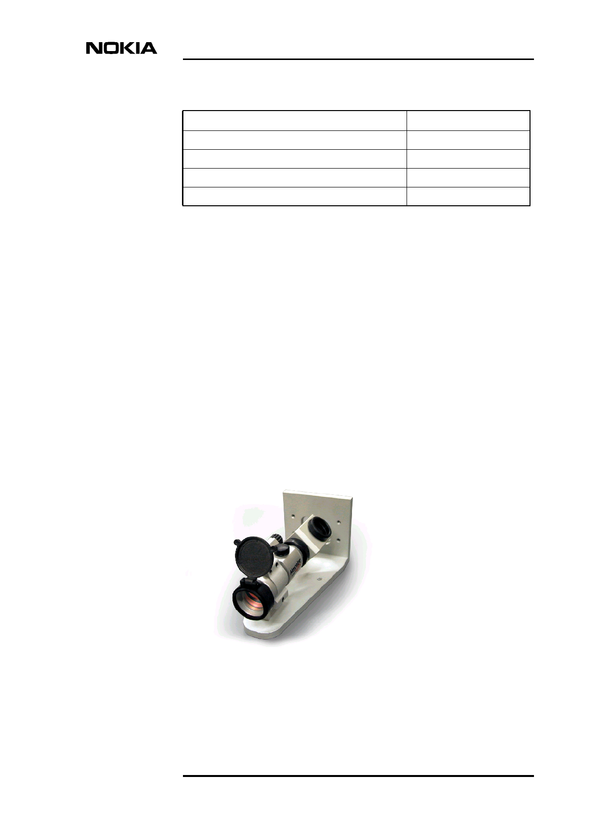
2.8.5 Optical Alignment Tool
Product code: T55875.01
The optical alignment tool is used to align the MetroHopper for optimum
efficiency.
The optical alignment tool is fitted on the MetroHopper mounting assembly
before the MetroHopper is fitted. Upon switching on, a red dot is visible through
the eyepiece and this can be adjusted for brightness. A coarse then a fine
alignment is carried using the red dot.
The red dot is aimed towards the centre of the far-end radio and the mounting
assembly is aligned accordingly. During the course of alignment, appropriate
screws are tightened to lock the mounting assembly in the aligned position.
When satisfied that alignment is complete, the optical alignment tool is switched
off and removed from the MetroHopper mounting assembly. The MetroHopper
can then be fitted to the mounting assembly.
Figure 20. Optical alignment tool
Live wire colour Brown
Neutral wire colour Blue
Earthing cable colour Green-yellow
Sheath colour Black
Table 34. Specifications for the DC power cable (Continued)
Code Detail
Solution Accessories
58 (66) © Nokia Corporation Draft DN99252966
Nokia Proprietary and Confidential Issue3-0en
Table 35. Specifications for the optical alignment tool
Item Details
Type Optical red dot alignment sight. ‘Aimpoint Comp’
sight with a 90oviewing angle and a mounting base
perpendicular to the optical axis of sight.
Manufacturer Aimpoint AB, Sweden
Application Used with MetroSite Alignment Unit, type
T55850.01
Alignment ranges Alignment range with 2x magnification lens, 0.5 to 1
km.
4x magnification lens version: 1 km
Optical characteristics Red dot size 3 MOA
Calibration Factory calibrated with the optical axis set
perpendicular to the base within 10 MOA. The unit
can be re-calibrated as necessary.
Power source Battery operated. One lithium DL1/3N battery or
similar.
Battery life: 150-250 h (average)
Mechanical characteristics Base has mechanical interface to alignment unit
(T55850.01)
Materials and surface
treatment
Anodised/painted aluminium; stainless steel
Required tools One 6 mm Allen key.

Attachments
DN99252966 © Nokia Corporation Draft 59 (66)
Issue 3-0 en Nokia Proprietary and Confidential
3Attachments
Attachment 1: Installation instructions for the Abis 75-ohm interface of
Nokia MetroSite with TZC75024 cable
For installation the following listed tools are needed:
• CS74863 Peeling Tool
• CS74862 Centre Contact Crimp Tool
• CS77550.01 Crimp Tool
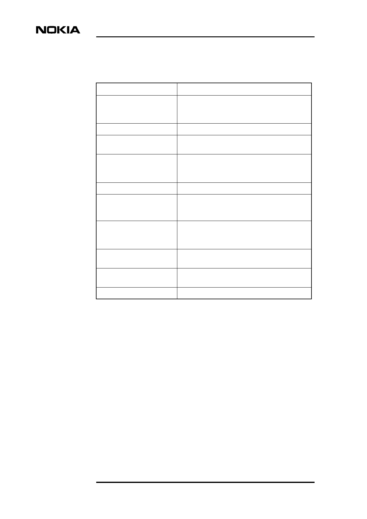
The connector consists of three parts: a ferrule, a jack and a body.
Solution Accessories
60 (66) © Nokia Corporation Draft DN99252966
Nokia Proprietary and Confidential Issue3-0en
Instructions:
1. Slide the shrinking sleeve and the ferrule onto the un-peeled part of the
cable.
2. Peel the cable as shown in the picture. The lengths of the peeled parts are:
21 mm (0.827"), 13 mm (0.512") and 4.5 mm (0.177").
3. Position the jack on the end of the cable. Push the cable into the crimping
tool so that the jack is inside the crimping hole, and crimp the jack onto the
conductor.
4. Push the body onto the cable so that the braid is outside the thinnest part of
the body.
5. Pull the ferrule over the braid onto the body so that the ferrule touches the
thick part of the body.
Attachments
DN99252966 © Nokia Corporation Draft 61 (66)
Issue 3-0 en Nokia Proprietary and Confidential
Note
6. Crimp the ferrule onto the body with the crimping tool CS77550.01. Use
the gap '4.52' on the tool.
7. Draw the shrinking sleeve over the ferrule and warm it to cause it to shrink
onto the ferrule.
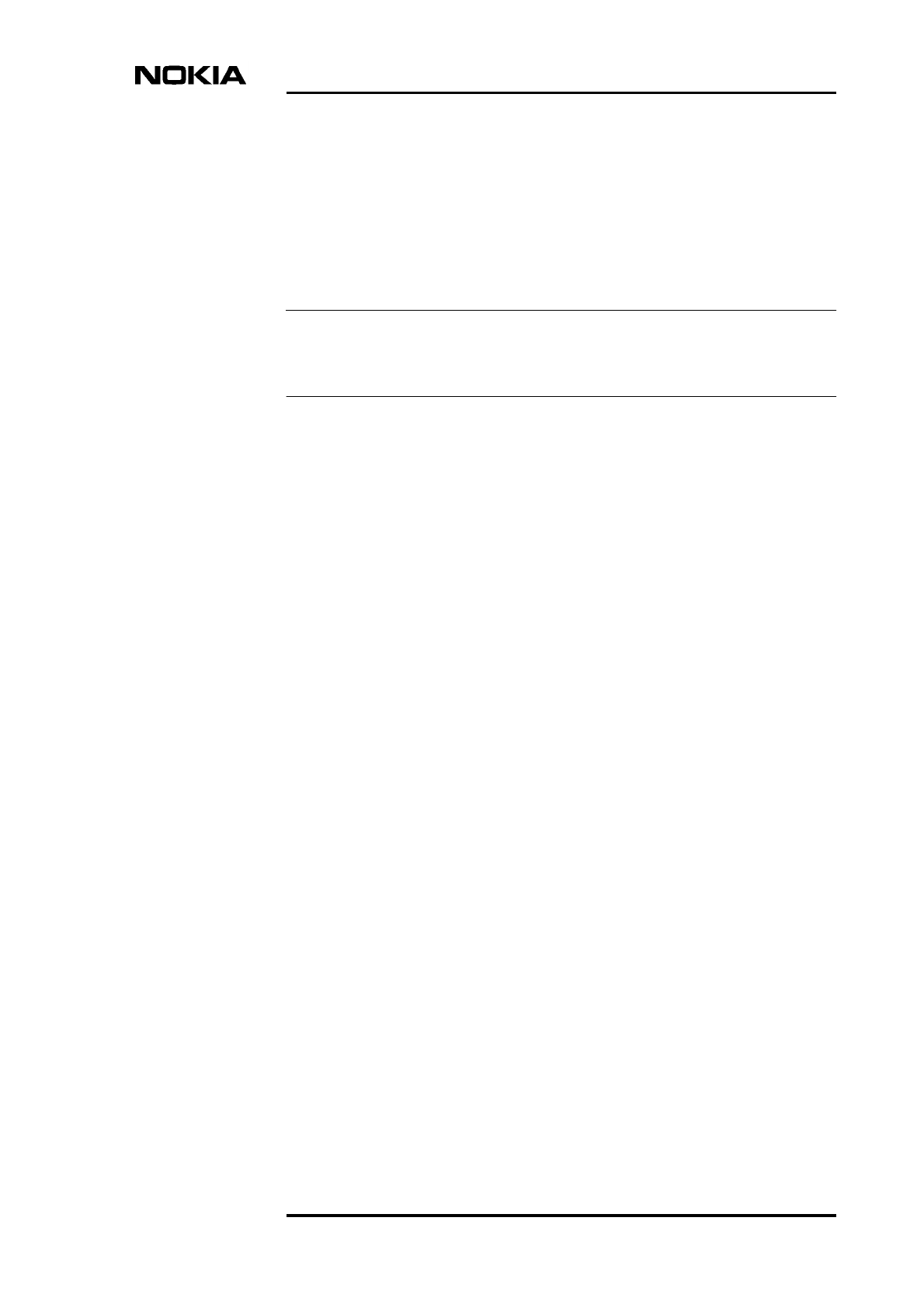
Attachment 2: Installation configuration for the Abis 120-ohm interface of
Nokia MetroSite.
This cable is provided already assembled but is shown here to identify all the parts
constituting an Abis 120-ohm interface.
A TQ connector is fitted to both ends of the cable. The wires connecting the TQ
connectors are coloured as follows (see figure):
OUT+ (pin 4): White stripe
OUT- (pin 3): White
IN+ (pin 2): Blue stripe
IN- (pin 1): Blue
Solution Accessories
62 (66) © Nokia Corporation Draft DN99252966
Nokia Proprietary and Confidential Issue3-0en
Attachment 3: Installation instructions for the AC power plug for Nokia
MetroSite.
The power feeder is a flexible rubber insulated cable with three multi-wire
conductors having dimensions of: 1.5 mm2 or 2.5 mm2 (AWG 15.5-13.5).
For installation the following listed tools are needed:
• Screwdriver (flat)
• Screwdriver (Philips)
Attachments
DN99252966 © Nokia Corporation Draft 63 (66)
Issue 3-0 en Nokia Proprietary and Confidential
Instructions:
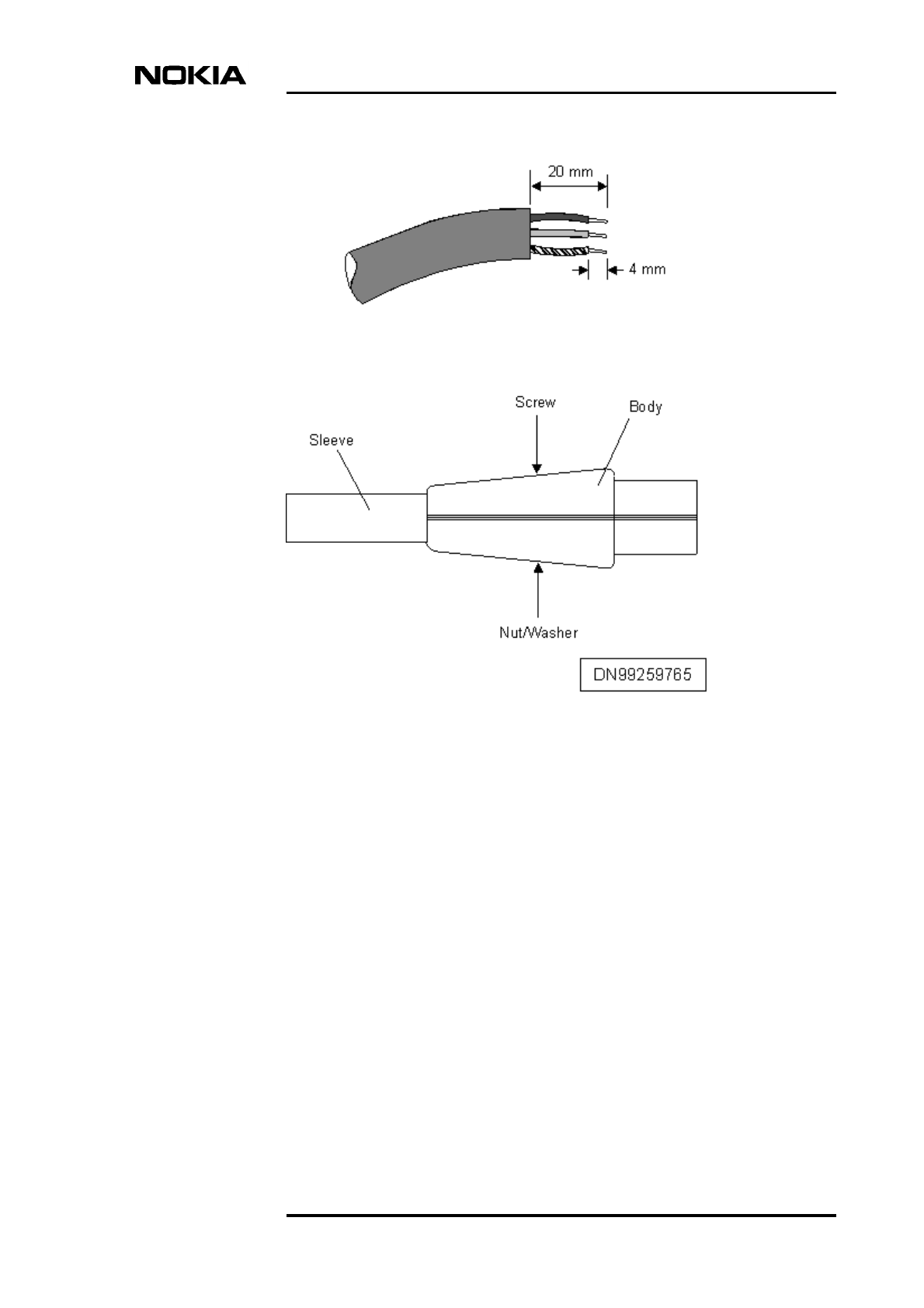
1. Strip the power feeder cable from its main insulation 20 mm (0.787").
2. Strip the inner conductors and cut them so that the blue and brown wires
are 20 mm (0.787") long and the yellow/green wire is slightly longer, at 25
mm (1"). The stripped area is 4 mm (0.157") long.
3. Undo the screw holding the body parts together and store the screw, nut and
washer in a safe place. Separate the two parts of the body.
4. Remove the sleeve then feed the cable (exposed end) through the sleeve
from the rear.
5. Pull the cable through sufficiently to enable the wires to be attached to the
plug connectors.
Solution Accessories
64 (66) © Nokia Corporation Draft DN99252966
Nokia Proprietary and Confidential Issue3-0en
Note
6. Undo each plug connector screw sufficiently to enable the cable wire to be
inserted and insert the wires in each connector.
The brown (live) wire to be inserted in the right-hand connector as viewed from
the front. The blue (neutral) wire is inserted into the left-hand connector, and the
yellow/green (earth) wire to the centre connector.
7. Tighten each screw in turn to fix the wires in the connectors.
8. Align the sleeve on the cable so that the raised end can be inserted into the
slot.
9. Place the two body parts together, making sure they are aligned, the wires
are clear of the body fixing hole and the sleeve is properly located in the
slot.
10. Fix the body parts together with the screw, nut and washer.
11. This procedure is to be repeated for the other end of the cable if the power
cable is to connect the MetroSite BBU to a MetroSite BTS.
If the cable is to be connected to a MetroHub, repeat steps 1 and 2 for the
other end of the cable. Connect that end to the MetroHub as described in
the MetroHub User Manual (Installation).
If the cable is to be connected to the mains power source then this is user
defined.
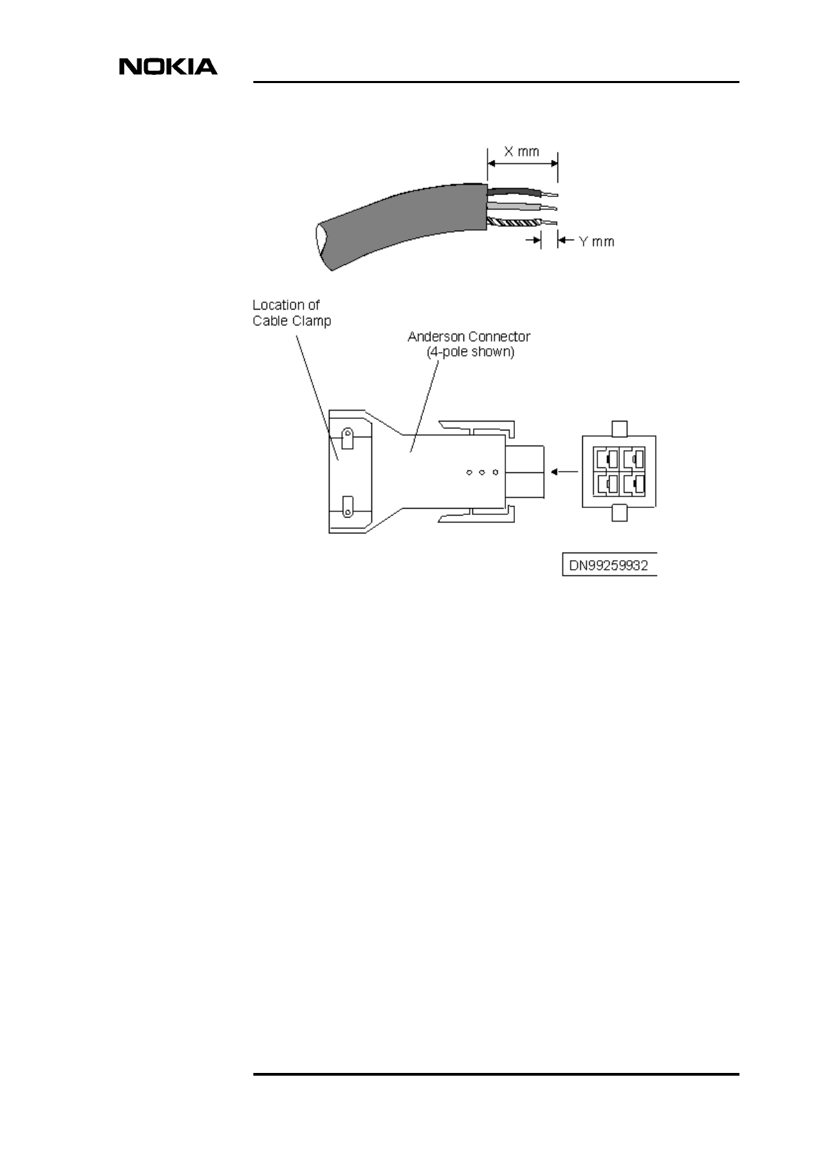
Attachment 4: Installation instructions for the DC power plug for Nokia
MetroSite
The power feeder is a flexible rubber insulated cable with three multi-wire
conductors having dimensions of: 1.5 mm2 or 2.5 mm2 (AWG 15.5-13.5).
Attachments
DN99252966 © Nokia Corporation Draft 65 (66)
Issue 3-0 en Nokia Proprietary and Confidential
Instructions:
1. Strip the power feeder cable from its main insulation 'X' mm (TBA).
2. Strip the inner conductors and cut them so that they are of equal length.
3. Strip each wire insulation to 'Y' mm (TBA) length using a sharp blade,
taking care not to cut any strands of wire.
4. Insert each wire, in turn, into a contact and using the crimping tool, crimp
the contact around the wire.
5. Undo the cable clamp to enable the cable to be inserted.
6. Push the contacts into the connector in their correct positions.It is very
important that the contacts are in the correct order in the connector.
7. If the cable is to connect the DC supply to a MetroSite BTS, the procedure
is to be repeated for the other end of the cable. If the cable is to connect the
DC supply to a MetroHub, refer to the MetroHub User Manual
(Installation)for the connection of the other end of the cable.

Solution Accessories
66 (66) © Nokia Corporation Draft DN99252966
Nokia Proprietary and Confidential Issue3-0en