Nokia Solutions and Networks WTPA-01 GSM 1900 Transceiver User Manual dn991444x3x0xen
Nokia Solutions and Networks GSM 1900 Transceiver dn991444x3x0xen
Contents
Product Desc

Nokia MetroSite EDGE Base Station
DN991444 © Nokia Corporation Draft 1 (98)
Issue 3-0 en Draft Nokia Proprietary and Confidential
Product Description

Product Description
2 (98) © Nokia Corporation Draft DN991444
Nokia Proprietary and Confidential Issue 3-0 en Draft
The information in this documentation is subject to change without notice and describes only
the product defined in the introduction of this documentation. This documentation is intended
for the use of Nokia's customers only for the purposes of the agreement under which the
documentation is submitted, and no part of it may be reproduced or transmitted in any form or
means without the prior written permission of Nokia. The documentation has been prepared to
be used by professional and properly trained personnel, and the customer assumes full
responsibility when using it. Nokia welcomes customer comments as part of the process of
continuous development and improvement of the documentation.
The information or statements given in this documentation concerning the suitability, capacity,
or performance of the mentioned hardware or software products cannot be considered binding
but shall be defined in the agreement made between Nokia and the customer. However, Nokia
has made all reasonable efforts to ensure that the instructions contained in the documentation
are adequate and free of material errors and omissions. Nokia will, if necessary, explain issues
which may not be covered by the documentation.
Nokia's liability for any errors in the documentation is limited to the documentary correction of
errors. NOKIA WILL NOT BE RESPONSIBLE IN ANY EVENT FOR ERRORS IN THIS
DOCUMENTATION OR FOR ANY DAMAGES, INCIDENTAL OR CONSEQUENTIAL
(INCLUDING MONETARY LOSSES), that might arise from the use of this documentation or
the information in it.
This documentation and the product it describes are considered protected by copyright
according to the applicable laws.
NOKIA logo is a registered trademark of Nokia Corporation.
Other product names mentioned in this documentation may be trademarks of their respective
companies, and they are mentioned for identification purposes only.
Copyright © Nokia Corporation 2002. All rights reserved.
DN991444 © Nokia Corporation Draft 3 (98)
Issue 3-0 en Draft Nokia Proprietary and Confidential
Hereby, Nokia Corporation, declares that this product is in compliance with the
essential requirements and other relevant provisions of Directive: 1999/5/EC.
The product is marked with the CE marking and Notified Body number according to the
Directive 1999/5/EC.
FCC FCC §15.21 - Information to user - This product is used as an intentional radiated
equipment and any changes or modifications on the equipment without any approval
by Nokia could void the user's authority to operate the equipment.
FCC §15.105 - Information to user - This equipment has been tested and found to
comply with the limits for a Class B digital device, pursuant to part 15 of the FCC
Rules. These limits are designed to provide reasonable protection against harmful
interference in a residential installation. This equipment generates, uses and can
radiate radio frequency energy and, if not installed and used in accordance with the
instructions, may cause harmful interference to radio communications. However, there
is no guarantee that interference will not occur in a particular installation. If this
equipment does cause harmful interference to radio or television reception, which can
be determined by turning the equipment off and on, the user is encouraged to try to
correct the interference by one or more of the following measures:
• Reorient or relocate the receiving antenna.
• Increase the separation between the equipment and receiver.
• Connect the equipment into an outlet on a circuit different from that to which the
receiver is connected.
• Consult the dealer or an experienced radio/TV technician for help.
0523

Product Description
4 (98) © Nokia Corporation Draft DN991444
Nokia Proprietary and Confidential Issue 3-0 en Draft

DN991444 © Nokia Corporation Draft 5 (98)
Issue 3-0 en Draft Nokia Proprietary and Confidential
Contents
Contents 5
List of tables 7
List of figures 9
1 About this document 13
2 Introduction to the Nokia MetroSite EDGE Base Station 15
2.1 Base station system 15
2.2 Nokia MetroSite EDGE Base Station 16
3 Nokia MetroSite EDGE Base Station features 19
3.1 Building capacity with the Nokia MetroSite EDGE Base Station 19
3.1.1 Four TRX BTS with flexible sectoring and dual band operation 19
3.1.2 Chaining of Nokia MetroSite EDGE base stations 20
3.1.3 RF power and sensitivity for microcellular applications 21
3.1.4 Smooth capacity expansion 21
3.2 High network quality 21
3.2.1 Receiver diversity 21
3.2.2 Frequency hopping 22
3.2.3 Antenna solution 22
3.3 Telecommunication features 23
3.3.1 General Packet Radio Service (GPRS) 24
3.3.2 Enhanced General Packet Radio Service (EGPRS) 24
3.4 Easy and fast deployment 24
3.4.1 Installation 24
3.4.2 Commissioning with the Nokia MetroSite BTS Manager 25
3.5 Advanced operation and maintenance 27
3.5.1 Integration of TRX and base control functions (BCF) 27
3.5.2 BTS diagnostics, alarms and TRX test 27
3.5.3 Battery backup with Nokia MetroSite Battery Backup 28
3.5.4 Temperature control 28
4 Applications 31
4.1 Building capacity with the Nokia MetroSite EDGE Base Station 31
4.2 Transmission with the Nokia MetroSite EDGE Base Station 36
5 Nokia MetroSite EDGE Base Station related software 39
5.1 Nokia MetroSite EDGE Base Station software 39
5.2 Nokia MetroSite BTS Manager software 40
5.3 BTS software updates 41
6 General function, construction and units 43
6.1 Nokia MetroSite EDGE Base Station general function 43
6.1.1 Signalling between network, BTS and MS 43
6.1.2 Nokia MetroSite EDGE Base Station internal function 45
6.2 Cabinet (HVMC) and cover (HVCU, WCUA) 48

Product Description
6 (98) © Nokia Corporation Draft DN991444
Nokia Proprietary and Confidential Issue 3-0 en Draft
6.3 Transceiver unit (HVTxx and WTxx) 52
6.3.1 Baseband module 54
6.3.2 RF module 56
6.3.3 External interfaces 59
6.4 Interface unit (VIFA) 59
6.4.1 External interfaces 60
6.5 Transmission unit (VXEA, VXTx, VXRB) 63
6.5.1 Unit alternatives for radio link transmission 63
6.5.2 Unit alternatives for wireline transmission 64
6.6 Power supply unit (HVSx) 68
6.6.1 Power supply unit alternatives 68
6.6.2 Output voltages 68
6.6.3 Connector types 69
6.7 Fan unit (HVMF) 70
7 Unit alternatives and other delivery items 73
8 Technical specifications 75
8.1 Dimensions and weights of plug-in units 84
8.1.1 Transceiver unit 84
8.1.2 Interface unit 84
8.1.3 Transmission unit 85
8.1.4 Power supply unit 85
8.2 System requirements for Nokia MetroSite BTS Manager 85
8.3 Basic telecommunication features 86
8.4 International recommendations 87
8.4.1 Common standards 87
8.4.2 Electrical standards 87
8.4.3 Environment 90
8.4.4 Mechanical standards 91
8.4.5 Base station interface equipment - related recommendations and
standards 92
Index 95

DN991444 © Nokia Corporation Draft 7 (98)
Issue 3-0 en Draft Nokia Proprietary and Confidential
List of tables
Table 1. Power level ranges for the Nokia MetroSite EDGE Base Station 21
Table 2. TRX interface connectors 59
Table 3. Pin configuration of the LMP connector 61
Table 4. Pin configuration of the Nokia Q1 connector 61
Table 5. Pin configurations of the EAC connector 62
Table 6. Pin configuration of a balanced TQ connector 65
Table 7. Power supply unit alternatives 68
Table 8. Power supply connector types 70
Table 9. Cooling fans details 71
Table 10. Transceiver unit alternatives 73
Table 11. Nokia MetroSite EDGE Base Station unit alternatives and other delivery
items 74
Table 12. Common technical data 75
Table 13. Specific technical data for the 5W GSM 900 TRX 76
Table 14. Specific technical data for the 5W GSM 1800 TRX 77
Table 15. Specific technical data for the 5W GSM 1900 TRX 78
Table 16. Specific technical data for the 5W GSM/EDGE 800 TRX 78
Table 17. Specific technical data for the 5W GSM/EDGE 900 TRX 79
Table 18. Specific technical data for the 5W GSM/EDGE 1800 TRX 80
Table 19. Specific technical data for the 5W GSM/EDGE 1900 TRX 81
Table 20. HW interfaces of Nokia MetroSite EDGE Base Station 82
Table 21. Transmission interfaces of Nokia MetroSite EDGE Base Station 83
Table 22. Flexbus cable characteristics 83
Table 23. Dimensions and weight of the TRX 84
Table 24. Dimensions and weight of the interface unit 84
Table 25. Dimensions and weight of the transmission unit 85
Table 26. Dimensions and weight of the power supply unit 85
Table 27. System requirements for Nokia MetroSite BTS Manager 86
Table 28. Common standards 87

Product Description
8 (98) © Nokia Corporation Draft DN991444
Nokia Proprietary and Confidential Issue 3-0 en Draft
Table 29. Input voltage standards 87
Table 30. Electrical safety standards 88
Table 31. Product specific EMC standards 88
Table 32. Basic EMC standards based on d-ETS 300 342-3:1997 89
Table 33. Additional EMC standards 90
Table 34. Environmental standards 91
Table 35. Mechanical standards 92
Table 36. Flexbus interface 92
Table 37. 2048 Kbit/s E1 interface 93
Table 38. 1544 Kbit/s T1 interface 94

DN991444 © Nokia Corporation Draft 9 (98)
Issue 3-0 en Draft Nokia Proprietary and Confidential
List of figures
Figure 1. Base station system (BSS) 16
Figure 2. Nokia MetroSite - an ideal solution for dense, urban environment 17
Figure 3. Nokia MetroSite BTS Manager Commissioning Wizard 26
Figure 4. Temperature management diagram 28
Figure 5. Roadside coverage with the Nokia MetroSite EDGE Base Station 31
Figure 6. Microcells built with the Nokia MetroSite EDGE Base Station 32
Figure 7. Four TRXs in one sector, single band configuration 33
Figure 8. (1+1)/(1+1) dual band configuration 34
Figure 9. 2+2 dual band configuration 35
Figure 10. Examples of transmission connections 37
Figure 11. Nokia MetroSite BTS Manager desktop 41
Figure 12. General principle of signalling between network, BTS and mobile
station 44
Figure 13. Nokia MetroSite EDGE Base Station block diagram 46
Figure 14. Power distribution in the Nokia MetroSite EDGE Base Station 48
Figure 15. Dimensions of the Nokia MetroSite EDGE Base Station 50
Figure 16. Arrangement of units 52
Figure 17. Transceiver unit 53
Figure 18. Block diagram of a Nokia MetroSite TRX 54
Figure 19. Block diagram of the baseband module 55
Figure 20. Block diagram of the RF module 57
Figure 21. Interface unit of the Nokia MetroSite EDGE Base Station 60
Figure 22. Pin order of the LMP connector 60
Figure 23. Pin order of the Q1 connector 61
Figure 24. Pin order of the EAC connector 62
Figure 25. Radio link transmission unit alternatives 64
Figure 26. Pin order of a balanced TQ connector 65
Figure 27. Wireline transmission unit alternatives 67
Figure 28. Power supply unit 69


DN991444 © Nokia Corporation Draft 11 (98)
Issue 3-0 en Draft Nokia Proprietary and Confidential
Summary of changes
Version 1, 12 November 1999.
Version 2, 22 June 2000:
• Added GSM to title and to body text
• Changed max. power to 5 W (Chapter 3.1.2)
• Added 5W TRX options (Chapter 6.3)
• Changed height of BTS (Figure 14, Table 8, and Table 9)
• Changed BBU backup time to 1hr (Chapter 3.5.3)
• Added power alternatives (Table 6). Added HVMF fan to Chapter 6.7
• Expanded Chapter 7 to include 5W TRXs (new Table 7)
• Added 5W TRX BTS power demand in Table 8
• Included 5 W power (Tables 12, 13, and 14)
Version 3 update, 7 March 2001:
• Revised throughout to include EDGE and to remove 1W TRXs. Comments
from this document’s technical review of 1 February 2001 incorporated.
Version 3 update, July 2002:
• Chaining feature and EGPRS descriptions added.
• 800 MHz TRX, NEBS cover (WCUA), +24 VDC power supply unit
added.

Product Description
12 (98) © Nokia Corporation Draft DN991444
Nokia Proprietary and Confidential Issue 3-0 en Draft

About this document
DN991444 © Nokia Corporation Draft 13 (98)
Issue 3-0 en Draft Nokia Proprietary and Confidential
Note
1About this document
This document describes the hardware, software, and functions of the Nokia
MetroSiteTM EDGE Base Station (BTS), including the 5W GSM TRX and 5W
GSM/EDGE TRX variants. Use this document as a reference for the following
information:
• Nokia MetroSite EDGE Base Station features
• Nokia MetroSite EDGE Base Station applications
• Nokia MetroSite EDGE Base Station software
• Nokia MetroSite BTS Manager
• Nokia MetroSite EDGE Base Station general function, construction and
units
• Nokia MetroSite EDGE Base Station technical data
• Nokia MetroSite EDGE Base Station design standards
Some products referred to in this document, such as Nokia MetroHubTM
Transmission Node, Nokia FlexiHopperTM Microwave Radio, and Nokia
MetroHopperTM Radio, may not be available in certain markets.

Product Description
14 (98) © Nokia Corporation Draft DN991444
Nokia Proprietary and Confidential Issue 3-0 en Draft

Introduction to the Nokia MetroSite EDGE Base Station
DN991444 © Nokia Corporation Draft 15 (98)
Issue 3-0 en Draft Nokia Proprietary and Confidential
2Introduction to the Nokia MetroSite
EDGE Base Station
This chapter describes the base station system (BSS) and the Nokia MetroSite
EDGE Base Station generally.
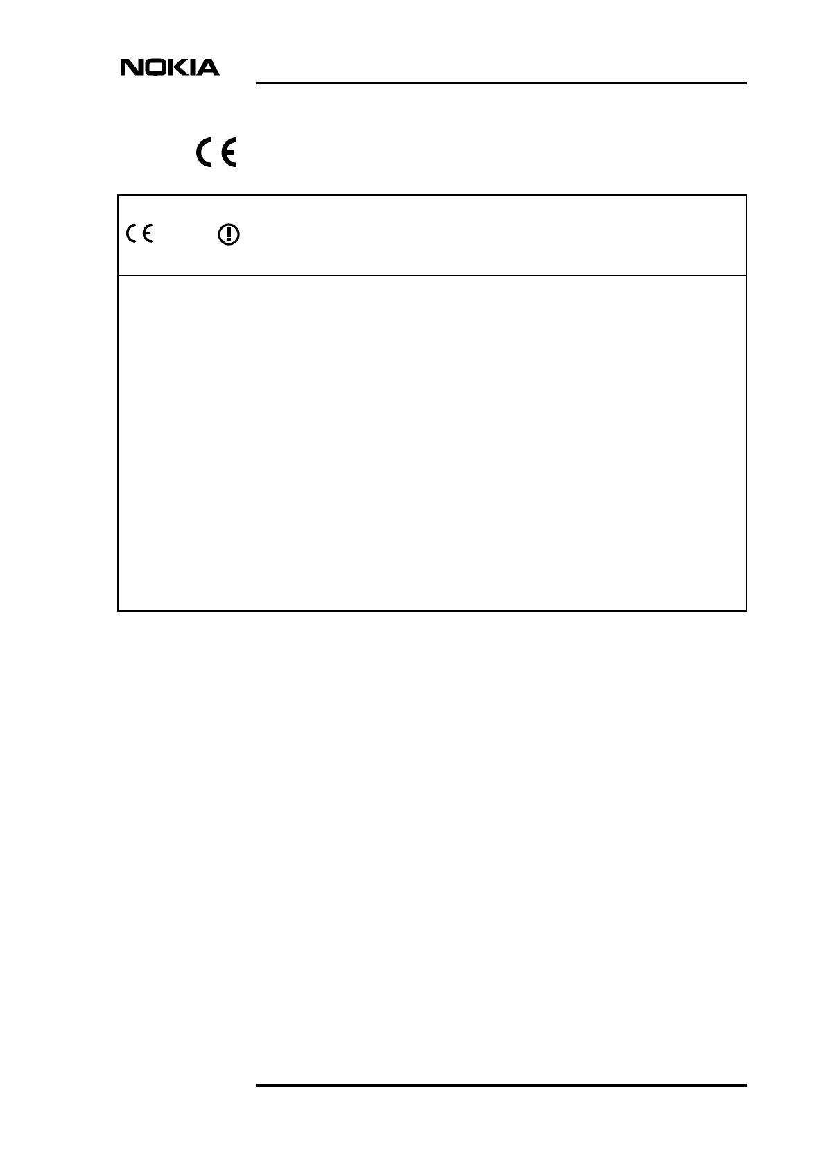
2.1 Base station system
In general terms, base stations perform the radio function for the base station
system. A base transceiver station (such as a Nokia MetroSite EDGE Base
Station) is connected to a transmission node (such as a Nokia MetroHub
Transmission Node) or directly to the base station controller (BSC) via the Abis
interface and to the mobile stations (MS) via the Air interface (see Figure 1).
The BSC is further connected to the mobile switching centre (MSC) and to the
operational support system (OSS).
Product Description
16 (98) © Nokia Corporation Draft DN991444
Nokia Proprietary and Confidential Issue 3-0 en Draft
Note
Figure 1. Base station system (BSS)
2.2 Nokia MetroSite EDGE Base Station
The Nokia MetroSite EDGE Base Station is a complete, all-climate base
transceiver station. It can be used in GSM 900, 1800 and 1900 and GSM/EDGE
800, 900, 1800 and 1900 systems, or as a dual band GSM 900/1800 or dual band
GSM/EDGE 900/1800, 800/1800 or 800/1900 BTS. Both omni and sectored
configurations are supported. The small-sized Nokia MetroSite EDGE Base
Station cabinet accommodates up to four transceiver units (TRXs).
The Nokia MetroSite EDGE Base Station can be fitted with 5W GSM TRXs or
5W GSM/EDGE TRXs.
The introduction of EDGE requires EDGE capable TRXs. EDGE also requires
CX 3.2 software (or later) to be available at the BSC.
Air interface
Transmission
node
BTS
BTS
BTS
Abis interface
Abis
interface Abis
interface
Abis
interface
BSC
Introduction to the Nokia MetroSite EDGE Base Station
DN991444 © Nokia Corporation Draft 17 (98)
Issue 3-0 en Draft Nokia Proprietary and Confidential
Note
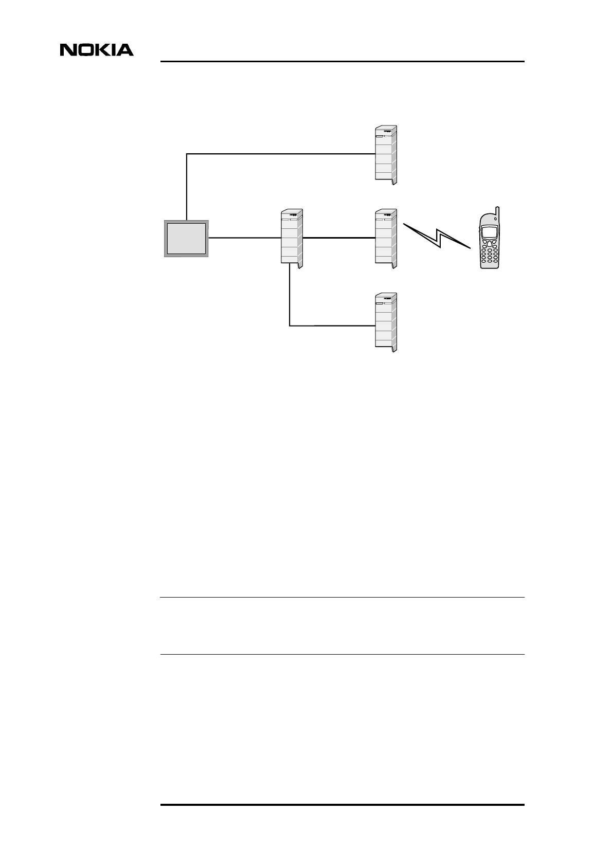
Figure 2. Nokia MetroSite - an ideal solution for dense, urban environment
The Nokia MetroSite EDGE Base Station is the core element in the Nokia
MetroSite Capacity Solution, which comprises complete sites equipped with
BTSs, transmission equipment, and auxiliary equipment. However, the Nokia
MetroSite EDGE Base Station can be integrated into other mobile network
applications as well.
The optimised RF performance, the versatile installation options, and the flexible
radio transmission solution using Nokia MetroHopper Radio for last-kilometre
access, allow for a large number of BTSs being installed in a small area.
Consequently, the Nokia MetroSite EDGE Base Station is an ideal solution for
special hot spots - like downtown areas, sports arenas, shopping centres,
underground stations and office buildings - where high capacity is needed.
For more information on the Nokia MetroHopper Radio, see the Nokia
MetroHopper Product Overview.

Product Description
18 (98) © Nokia Corporation Draft DN991444
Nokia Proprietary and Confidential Issue 3-0 en Draft
In order to ensure a high quality of calls, the Nokia MetroSite EDGE Base Station
supports versatile features, such as frequency hopping.
Due to its compact size, low weight, and high level of integration, the Nokia
MetroSite EDGE Base Station is fast and easy to install, either indoors or
outdoors with minimal preparations. Both wall and pole installations are
supported. From the network planning point of view, the Nokia MetroSite EDGE
Base Station can be installed at optimal locations. The plug-in construction of the
Nokia MetroSite EDGE Base Station also provides great flexibility when, for
example, capacity expansion is considered.
In addition to its other versatile and advanced properties, the Nokia MetroSite
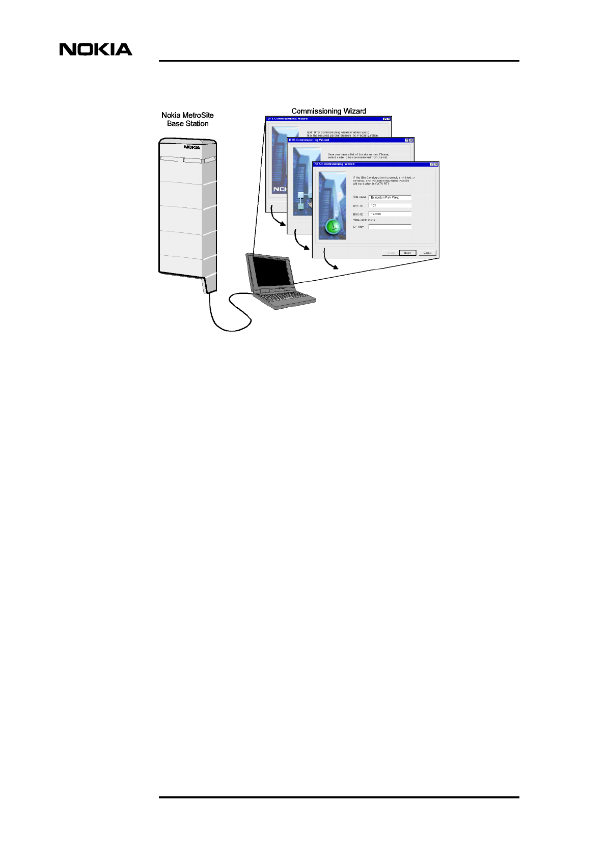
EDGE Base Station is designed for easy commissioning. This has been achieved
by the Nokia MetroSite BTS Manager, which incorporates a commissioning
wizard and BTS configuration autodetection.
The Nokia MetroSite EDGE base station’s size and ease of deployment help the
operator to reduce site planning and site acquisition costs. The fast start-up and
the quick integration into the network enable immediate revenue flow to the
operator. Furthermore, the operational costs are low as the BTS management is to
a large extent carried out remotely from the OSS.

Nokia MetroSite EDGE Base Station features
DN991444 © Nokia Corporation Draft 19 (98)
Issue 3-0 en Draft Nokia Proprietary and Confidential
3Nokia MetroSite EDGE Base Station
features
This chapter describes the technical properties of the Nokia MetroSite EDGE
Base Station that contribute to:
• Microcellular capacity
• Network quality
• Data services
• Deployment
• Operation and maintenance
A description of the advanced telecommunication features is also presented here.
A detailed description of technical features supported by the Nokia MetroSite
EDGE Base Station can be found in the Feature Descriptions document delivered
in the Nokia MetroSite Base Station Software Release Binder. For a list of Nokia
MetroSite EDGE Base Station properties, see also Chapter 8 in this document.
3.1 Building capacity with the Nokia MetroSite EDGE
Base Station
The features described in this section accommodate the efficient building of
capacity such as microcellular, building infill and roadside coverage.
3.1.1 Four TRX BTS with flexible sectoring and dual band operation
One Nokia MetroSite EDGE Base Station incorporates up to four TRXs and thus
provides sufficient capacity to handle a large amount of telecommunication
traffic. The Nokia MetroSite EDGE Base Station can be sectored very flexibly.
Every TRX has its own antenna connector. Every TRX also incorporates a duplex
filter, and one antenna therefore handles both transmitting and receiving. Any cell
can incorporate up to four TRXs and, on the other hand, every TRX can form a
sector of its own within a cell. Consequently, the maximum number of sectors for
a stand-alone BTS is four.

Product Description
20 (98) © Nokia Corporation Draft DN991444
Nokia Proprietary and Confidential Issue 3-0 en Draft
Note
The dual band feature enables the operator to configure any sector to operate
either on a 900 or 1800 MHz frequency, thus increasing the capacity of the
network. With CX 3.2 software, or later, the 800/1800 MHz and 800/1900 MHz
dual band frequencies are also possible.
More information on the coverage areas created with different sectoring options
can be found in Section 4.1 in this document.
The term “cell” is used in the network management system (NMS) context,
referring to the coverage area of transceivers from the same base station.
3.1.2 Chaining of Nokia MetroSite EDGE base stations
Internal bus and Abis chaining are both possible with the Nokia MetroSite EDGE
Base Station. For more information on Abis chaining, refer to Section 4.2.
To further increase the capacity expansion possibilities, Nokia MetroSite EDGE
base stations can be chained as one BCF object to include up to 12 TRXs.
Chaining is done by extending the BTS internal buses through the extension
interface on the interface unit. Each BTS is connected to the next BTS in the chain
with only one cable (up to five metres). Only one of the BTSs (the master BTS)
incorporates a transmission unit (FXC type).
One BTS acts as the master BTS, in which the master TRX of the chain is located.
However, each BTS has a dedicated TRX to control the heating and cooling
functions. The chained BTSs share the same frame clock (FCLK) and frame
number and the sector configuration is therefore not limited by the cabinet
boundaries.
The chain can be commissioned in various diversity configurations. For example,
a chain with three BTSs could be configured with two sectors and six TRXs per
sector.
The Nokia MetroSite EDGE Base Station can also be connected to a Nokia
MetroHub Transmission Node. In this case, the BTS cabinet must incorporate a
transmission unit.
Nokia MetroSite EDGE Base Station features
DN991444 © Nokia Corporation Draft 21 (98)
Issue 3-0 en Draft Nokia Proprietary and Confidential
3.1.3 RF power and sensitivity for microcellular applications
The RF performance of the Nokia MetroSite EDGE Base Station is suitable for
microcellular, building infill and roadside coverage applications. The maximum
RF power of the Nokia MetroSite EDGE Base Station transmitter is 5 W at the
antenna connector. The maximum RF power of the Nokia MetroSite EDGE Base
Station in EDGE modulation mode is 3.2 W. The RX sensitivity is better than -
106 dBm. The output power and the receiver sensitivity of the Nokia MetroSite
EDGE Base Station, together with the use of surrounding buildings to limit the
cell size, allow efficient frequency re-use with minimised interference.
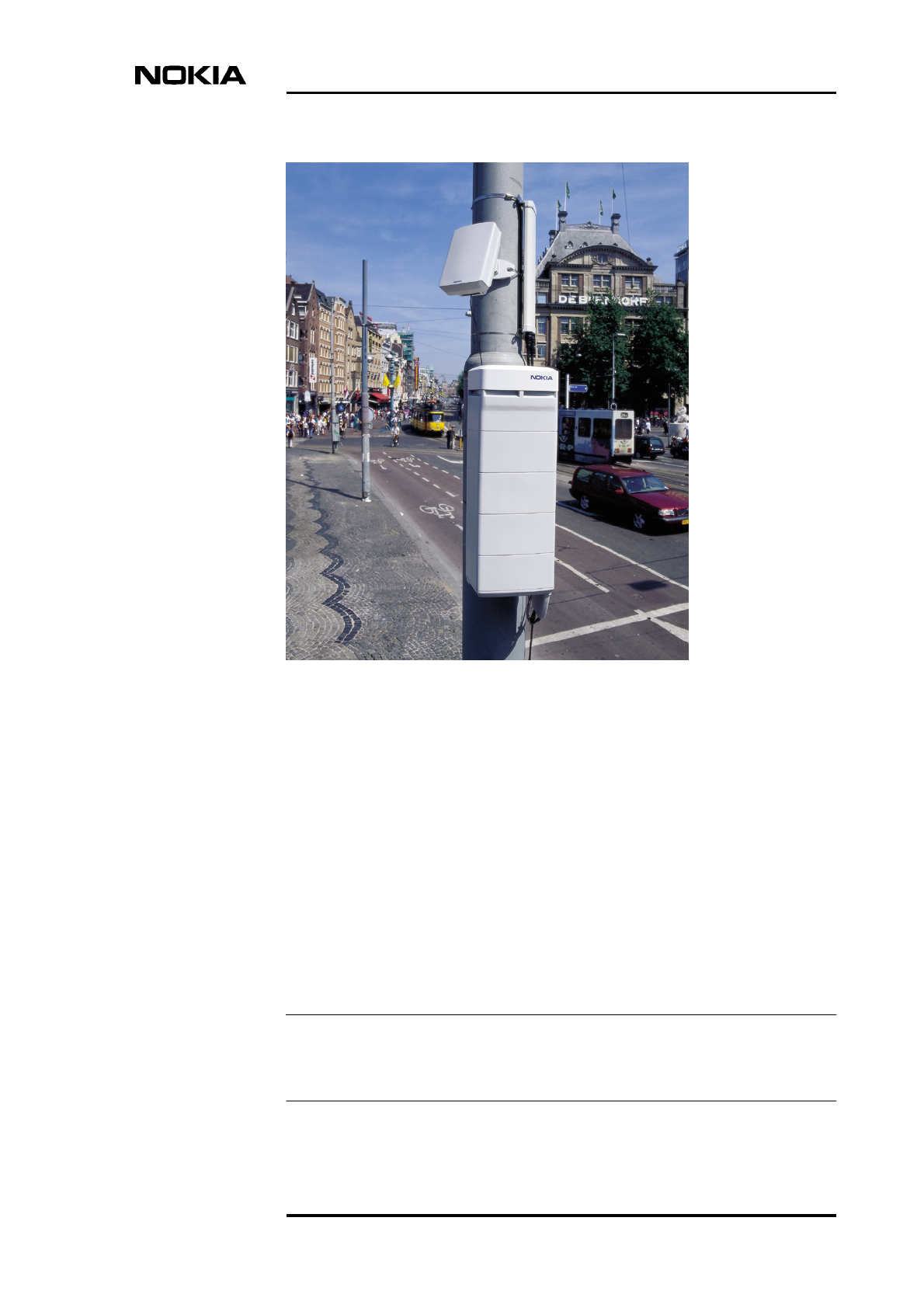
The dynamic power level range of the transmitter and the static broadcast control
channel (BCCH) power level range are shown in Table 1.
3.1.4 Smooth capacity expansion
As the operator’s demand for capacity grows, additional TRXs can be installed to
the Nokia MetroSite EDGE Base Station during operation without interrupting
the BTS service.
3.2 High network quality
The Nokia MetroSite EDGE Base Station increases the capacity of the network
and also maintains the quality of telecommunication traffic. This section
describes the features that contribute to the high network quality.
3.2.1 Receiver diversity
Receiver diversity (also known as uplink diversity) is available in the Nokia
MetroSite EDGE Base Station when two or more TRXs belong to the same
sector.
Table 1. Power level ranges for the Nokia MetroSite EDGE Base Station
Property GMSK modulation 8-PSK modulation
Static power level range (BCCH) 18 dB 10 dB
Total power level range (static +
dynamic)
30 dB 16 dB
Step size 2 dB 2 dB

Product Description
22 (98) © Nokia Corporation Draft DN991444
Nokia Proprietary and Confidential Issue 3-0 en Draft
Multipath propagation of the radio signal may cause local variations of signal
strength. Deep fades, particularly when the mobile station is near a cell border,
reduce the quality of the received signal. To minimise this effect, a spatial or
polarisation receiver diversity can be used, which means that two different paths
are used for the received signals.
Antennas are placed physically apart or they employ different polarisation so that
correlation between received signals is minimised. It is probable that even if one
of the receiver branches suffers from a deep fading drop, the other receives a
signal of sufficient quality. The two separate paths are processed in the baseband
section of the BTS transceiver, and the pre-detection weighted summing method
is used to combine the signals of the two branches.
Diversity can be enabled or disabled from the BSC. When diversity is employed,
the BTS must be physically equipped according to the logical sector
configuration at the BSC.
3.2.2 Frequency hopping
The Nokia MetroSite EDGE Base Station supports synthesised (RF) frequency
hopping when there are at least two TRXs in the same sector.
The most significant property of frequency hopping is that it enables averaging of
the interference to RF signal between network users. Frequency hopping can be
used to minimise signal quality degradation caused by frequency selective fading,
especially for slow moving MSs and narrow band interfering signals.
Synthesised frequency hopping enables each TRX to change frequency on
successive time slots, so that a given carrier can hop at several frequencies in
quick succession.
It is possible to use either a cyclic or random frequency hopping scheme as
defined in GSM 05.02, 05.08 recommendations.
3.2.3 Antenna solution
The MetroSite antenna is a small and unobtrusive dual band antenna designed for
microcellular, building infill and roadside coverage. It is a directional two-port
antenna with two antenna elements in one casing. This means that two TRXs can
be connected to one antenna. The gain of the antenna is 6 dBi and it provides 130°
coverage.
Other directional, omnidirectional and cross-polarised antennas can also be used
with the Nokia MetroSite EDGE Base Station. Furthermore, distributed antenna
systems (DAS), which are primarily used for building fill-in coverage, can be
employed.

Nokia MetroSite EDGE Base Station features
DN991444 © Nokia Corporation Draft 23 (98)
Issue 3-0 en Draft Nokia Proprietary and Confidential
When the Nokia MetroSite EDGE Base Station itself is installed inside a
building, the antennas can be located outdoors. The size of antenna feeders, 1/4”
and 3/8”, support the flexibility of installation.
The TRX test includes an antenna cable detection feature which, in most of the
cases, verifies whether the cable connection between the TRX and the antenna is
free of faults.
3.3 Telecommunication features
The most important telecommunication features supported by the Nokia
MetroSite EDGE Base Station software are discussed in this section. The basic
features are presented as a list in Section 8.3. A detailed description of all the
telecommunication features can be found in the software release documentation.
Half rate speech coding
The use of half rate (HR) speech coding makes it possible to almost double the
amount of available traffic channels on the radio path. This is achieved with the
existing transmission lines on the Abis interface. Half rate coding enables the use
of 8 Kbit/s channels.
Enhanced full rate speech coding
Enhanced full rate (EFR) speech coding improves the voice quality in all channel
conditions. The coding is based on improvements made for half rate coding
applied to the existing GSM full rate channel coding.
Support for data services
The Nokia MetroSite EDGE Base Station supports a number of features that
enable efficient data traffic. The most advanced of those features are dealt with
here. See also Section 3.3.1 in this document.
•High Speed Circuit Switched Data (HSCD). This feature provides
accelerated data rates for the end-user applications such as browsing the
Internet, file transfer and facsimile.
•14.4 Kbit/s GSM data services provide accelerated user data rates at 14.4
Kbit/s level. This feature can be combined with HSCSD.
•Non-transparent and transparent data (9600, 4800, 2400 bit/s). Non-
transparent means that the data rate can be changed automatically during
the call (due to increased traffic, for example). Transparent data uses a
fixed data rate throughout the duration of a call.

Product Description
24 (98) © Nokia Corporation Draft DN991444
Nokia Proprietary and Confidential Issue 3-0 en Draft
3.3.1 General Packet Radio Service (GPRS)
GPRS is designed to make the GSM data services more compatible with LAN,
WAN, and the Internet. In GPRS, the radio resources are used only when there
actually is data to be sent or received. GPRS also provides immediate
connectivity and very short set-up for sending a data packet. The throughput is as
high as in high speed circuit switched data (HSCSD). The Nokia MetroSite
EDGE Base Station supports GPRS coding schemes 1 and 2.
3.3.2 Enhanced General Packet Radio Service (EGPRS)
EGPRS is built on top of GPRS to increase the data rate of GPRS by applying
EDGE modulation and increasing the Air interface throughput. The data rate of
GPRS is increased up to threefold with EGPRS. The Nokia MetroSite EDGE
Base Station supports EGPRS modulation and coding schemes (MCS) 1 to 7.
EGPRS requires EDGE capable TRXs to be fitted in the BTS and CX 3.2
software or later.
3.4 Easy and fast deployment
This section describes the installation and commissioning procedures of the
Nokia MetroSite EDGE Base Station. The detailed task-oriented instructions can
be found in Nokia MetroSite EDGE Base Station: Installation and in Nokia
MetroSite EDGE Base Station: Commissioning.
3.4.1 Installation
Variety of installation possibilities
Due to its small size, unobtrusive appearance, low weight, and high level of
integration, the Nokia MetroSite EDGE Base Station accommodates a variety of
new installation possibilities. The extended environmental performance of the
Nokia MetroSite EDGE Base Station enables installation indoors and outdoors,
even in extreme climatic conditions. Mounting options are available for both wall
and pole installations. The Nokia MetroSite EDGE Base Station can also be
mounted horizontally on its back. For more information on mounting positions
refer to Nokia MetroSite EDGE Base Station: Requirements for Installation and
Operation.
Delivery and installation procedure
The Nokia MetroSite EDGE Base Station is delivered to the site with the ordered
plug-in units pre-installed. Shield units are installed in those unit slots that are not
occupied by functional units. The purpose of shield units is to provide protection
for the backplane connectors, ensure optimal air flow inside the cabinet, and
provide EMC and weather shielding for the BTS.

Nokia MetroSite EDGE Base Station features
DN991444 © Nokia Corporation Draft 25 (98)
Issue 3-0 en Draft Nokia Proprietary and Confidential
After unpacking the delivery, some of the units can be removed from the BTS to
make it easier to handle. Usually, removing only the TRXs makes the Nokia
MetroSite EDGE Base Station light enough to handle.
The Nokia MetroSite EDGE Base Station is then installed on a wall or a pole. In
wall mountings, the packing cardboard can be used as a template for drilling the
anchor screw holes to the wall. In pole mountings, an additional pole mounting
kit is used to attach the BTS to the installation pole.
After the removed plug-in units are reinstalled, the cabinet ground and power
cables are connected. The next step is to connect the diversity cables,
transmission cables and antenna cables. Then the BTS is powered up and
commissioning is started. Finally, the lock and the cover are installed to the BTS.
3.4.2 Commissioning with the Nokia MetroSite BTS Manager
Nokia MetroSite BTS Manager is a PC-based tool which includes a
commissioning wizard that guides the user throughout the whole commissioning
process.
Autodetection
The BTS software includes an autodetection feature which identifies the BTS
hardware. This reduces the time spent for commissioning as the user does not
have to create a separate HW database for the BTS. The system data is replicated
to each TRX so that none of the BTS parameters are lost when the units are
replaced.
No external measuring devices are needed for BTS commissioning tests.
The task-oriented instructions for each step can be found in Nokia MetroSite
EDGE Base Station: Commissioning document.
Product Description
26 (98) © Nokia Corporation Draft DN991444
Nokia Proprietary and Confidential Issue 3-0 en Draft
Figure 3. Nokia MetroSite BTS Manager Commissioning Wizard
Manual commissioning
Before the commissioning at the BTS site can be started, the following tasks must
be performed:
• The LAPD links must be created at the BSC
• The PCM port at the BSC must be set to active
The commissioning procedure performed on site with the Nokia MetroSite BTS
Manager includes the following steps:
• Transmission configuration
• Checking alarms and EACs
• Running the tests
• Creating the BTS commissioning report
In the near future, the use of the Site Configuration File (SCF) will considerably
ease the commissioning as most of the parameters can be fed directly from the
file, for example, the Abis time slot allocation can be automated.
The Nokia MetroSite BTS Manager automatically produces a commissioning
report at the end of the commissioning process.

Nokia MetroSite EDGE Base Station features
DN991444 © Nokia Corporation Draft 27 (98)
Issue 3-0 en Draft Nokia Proprietary and Confidential
3.5 Advanced operation and maintenance
The features concerning the operation and maintenance (O&M) of the Nokia
MetroSite EDGE Base Station are described in this section.
During operation, the Nokia MetroSite EDGE Base Station is managed remotely
from the OSS. Site visits to carry out routine O&M tasks are not usually needed.
3.5.1 Integration of TRX and base control functions (BCF)
One of the TRXs is configured as the master TRX of the BTS. Physically there is
no difference between the master TRX and the slave TRXs. In addition to the
normal TRX functions, the master TRX handles the BTS operation and
maintenance functions. Consequently, there is no need for a dedicated plug-in
unit to handle these functions. For more information refer to Section 6.1.2. The
O&M signalling and TRX signalling can also be combined into one channel to
optimise the use of transmission capacity.
3.5.2 BTS diagnostics, alarms and TRX test
Alarm diagnostics
The Nokia MetroSite EDGE Base Station features a BTS diagnostics system that
considerably reduces the number of alarms. Relevant alarm information is easily
accessible and understandable. A detailed description of the Nokia MetroSite
EDGE Base Station alarms can be found in the software release documentation.
The alarm diagnostics system filters out spurious alarms, reporting only those
alarms that directly affect the BTS service level. The alarms are addressed to the
unit level, which helps the maintenance engineers locate the faulty unit.
In the case of a mains power failure, the Nokia MetroSite EDGE Base Station
provides sufficient backup time for an alarm to be sent to the BSC.
TRX test
The TRX test is a multipurpose test designed for testing the total performance of
the intended TRX and Radio Time Slot (RTS). The test can be run locally from
the Nokia MetroSite BTS Manager, or remotely from the BSC/OSS when the
Abis connection is established. Locally, the TRX test is usually performed during
commissioning of the Nokia MetroSite EDGE Base Station.
Product Description
28 (98) © Nokia Corporation Draft DN991444
Nokia Proprietary and Confidential Issue 3-0 en Draft
The TRX test covers all functions between the Abis and Air interfaces: digital and
RF parts, antenna cable detection, RX sensitivity, and TX level. The main reason
for providing a single multipurpose test is to minimise the total test time; once the
time slot is reserved for testing, the test time is used effectively. The test utilises
the multifunctional RF loop and it is automatically performed for both RX
branches. The test time is approximately 15 seconds. The test can be used as an
RF performance supervision test when performed according to a regular schedule
from the NMS/2000.
For more information on the TRX test refer to the Software Release Binder.
3.5.3 Battery backup with Nokia MetroSite Battery Backup
If additional battery backup is needed, the Nokia MetroSite Battery Backup unit
can be used for this purpose. The Nokia MetroSite Battery Backup provides one
hour backup time for the Nokia MetroSite EDGE Base Station operating at 400
W. The Nokia MetroSite Battery Backup is an external unit with the same
appearance and mounting options as the Nokia MetroSite Base Station itself.
For more information on Nokia MetroSite Battery Backup, refer to Nokia
MetroSite Battery Backup User Manual.
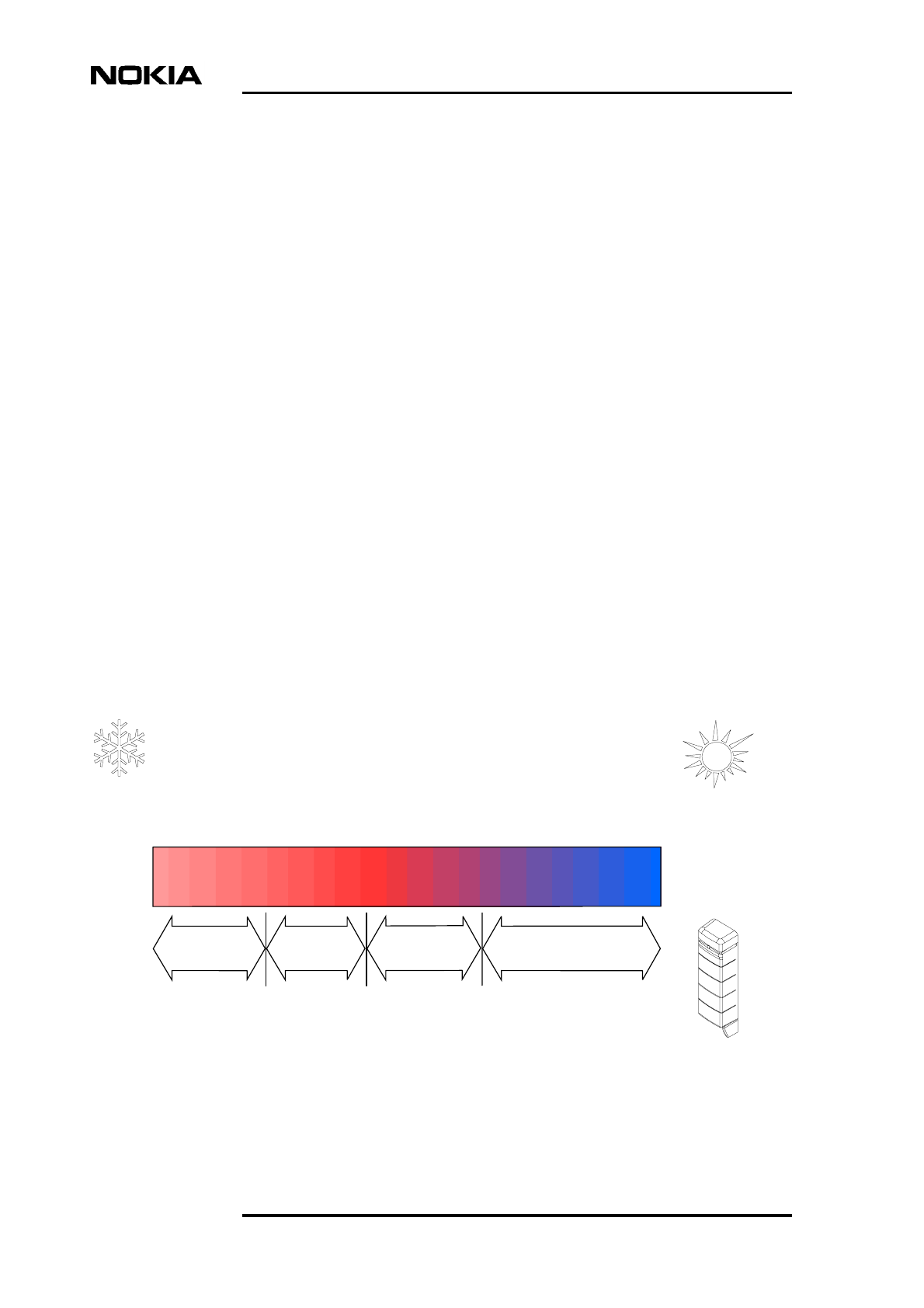
3.5.4 Temperature control
The Nokia MetroSite EDGE Base Station operates in the ambient temperatures
ranging from -40ºC to +50ºC (-40ºF to +122ºF), solar radiation 1120 W/m2.
Figure 4. Temperature management diagram
-40OC
-40OF
-10OC
+14OF
+10OC
+50OF
+20OC
+68OF
+50OC
+122OF
HEATING COOLING
full
heating
reduced
heating
cooling on
variable fan speed
heating off/
cooling off

Nokia MetroSite EDGE Base Station features
DN991444 © Nokia Corporation Draft 29 (98)
Issue 3-0 en Draft Nokia Proprietary and Confidential
The BTS has a cooling fan and built-in heaters to provide a smooth temperature
controlling facility. The BTS software controls the heating and cooling to provide
operation conditions which are as stable as possible. Heating and cooling are
adjusted gradually to ensure low temperature gradients and noise levels. The
temperature is continuously monitored with sensors placed on active units.
The heater elements are located inside the transceiver and transmission units.
When the BTS starts up in an extremely cold environment, the units are warmed
up to the operation temperature range (-10ºC or +14ºF within each TRX) before
the actual BTS operation starts.
The fan unit generates the cooling air flow inside the BTS. The fan unit has 16
speeds, ensuring low temperature gradients and noise levels.
If the temperature of any unit rises too high, due to a broken fan unit or too hot
conditions on the site for example, the TRX issues an analysed temperature alarm
to the BSC. The master TRX then shuts down the appropriate TRX. Similarly, if
the power supply is overheated, the master TRX switches off the power for all
units. The power supply switches the power back on when the temperature has
returned to the operational range.
During operation, the master TRX starts the heating process if the internal
temperature drops below the specified limit.

Product Description
30 (98) © Nokia Corporation Draft DN991444
Nokia Proprietary and Confidential Issue 3-0 en Draft
Applications
DN991444 © Nokia Corporation Draft 31 (98)
Issue 3-0 en Draft Nokia Proprietary and Confidential
4Applications
This chapter describes the typical applications of the Nokia MetroSite EDGE
Base Station including the transmission alternatives.
4.1 Building capacity with the Nokia MetroSite EDGE
Base Station
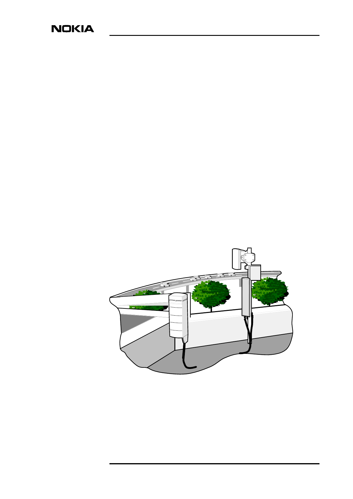
The Nokia MetroSite EDGE Base Station can be used for building capacity in
areas of heavy telecommunication traffic, such as for building infill, street
corners, sports arenas, shopping centres, and underground stations. It can also be
used for coverage of gaps in networks, such as for unfriendly terrain or roadside
coverage.
Figure 5. Roadside coverage with the Nokia MetroSite EDGE Base Station
Product Description
32 (98) © Nokia Corporation Draft DN991444
Nokia Proprietary and Confidential Issue 3-0 en Draft
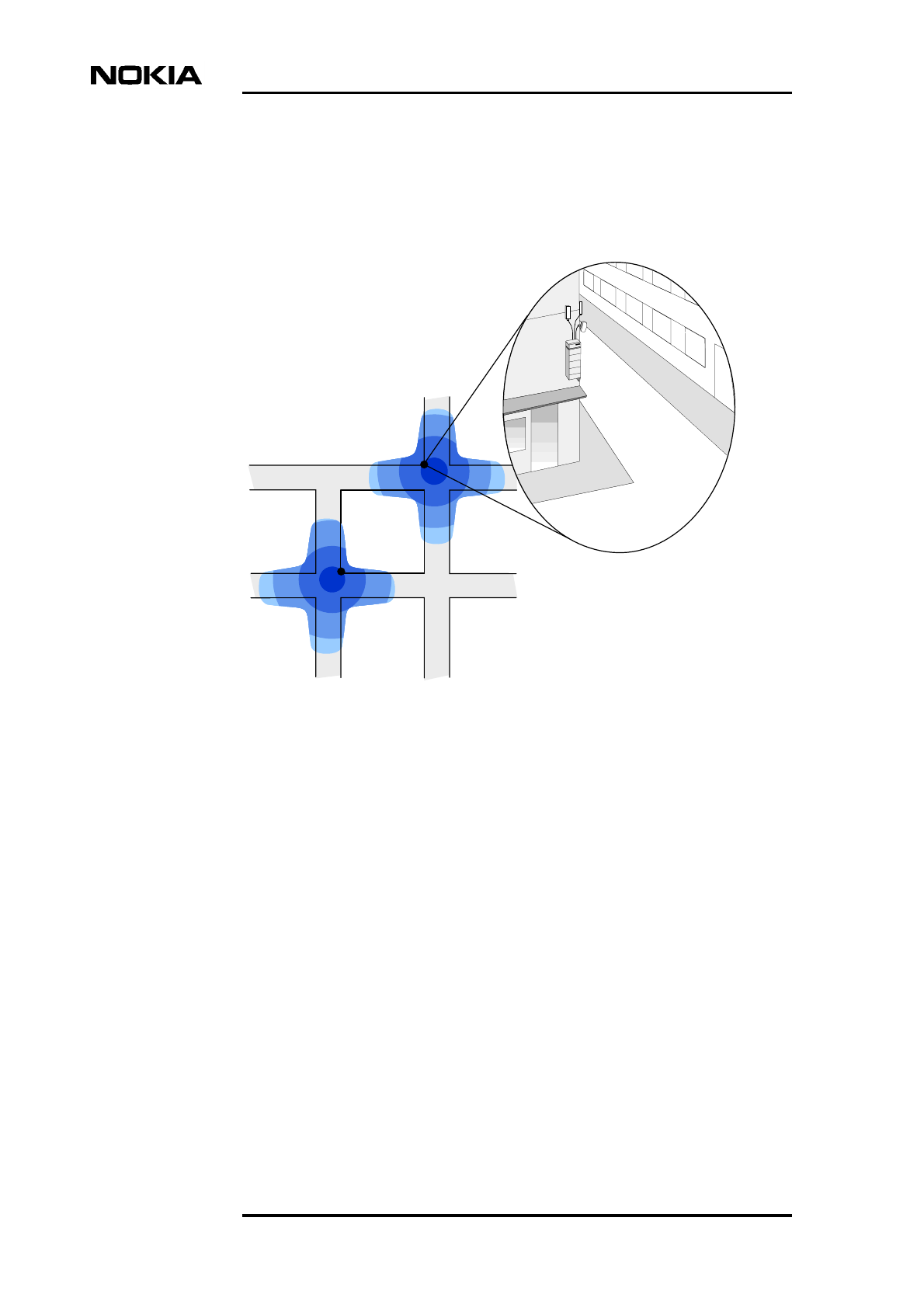
Efficient frequency re-use requires that the size of the coverage area (cell) be
limited. Figure 6 shows how the buildings surrounding the Nokia MetroSite
EDGE Base Station can be used to limit the cell size and shape in an urban
environment.
Figure 6. Microcells built with the Nokia MetroSite EDGE Base Station
The Nokia MetroSite EDGE Base Station can be sectored freely. A sector
consists of one broadcast control channel (BCCH) TRX and, often, one to three
traffic channel (TCH) TRXs. The maximum number of TRXs in one sector is
four.
At the BSC, one of the slave TRXs is by default defined as the BCCH TRX. The
BCCH TRX the most likely TRX to need replacement and a slave TRX can be
replaced without interrupting the BTS operation. If desired, the BCCH can be
forced on the master TRX by using the preferred BCCH feature at the BSC.
By using the different sectoring possibilities provided by the Nokia MetroSite
EDGE Base Station and by directing the antennas, different types of coverage
areas can be created. The actual shape of the coverage areas varies depending on
the environment.
BTS
BTS
Applications
DN991444 © Nokia Corporation Draft 33 (98)
Issue 3-0 en Draft Nokia Proprietary and Confidential
TRXs from different sectors can be connected to one antenna. The following
examples assume that the MetroSite antenna is used; the diversity applications
may differ from the ones presented here if different antenna types are used.
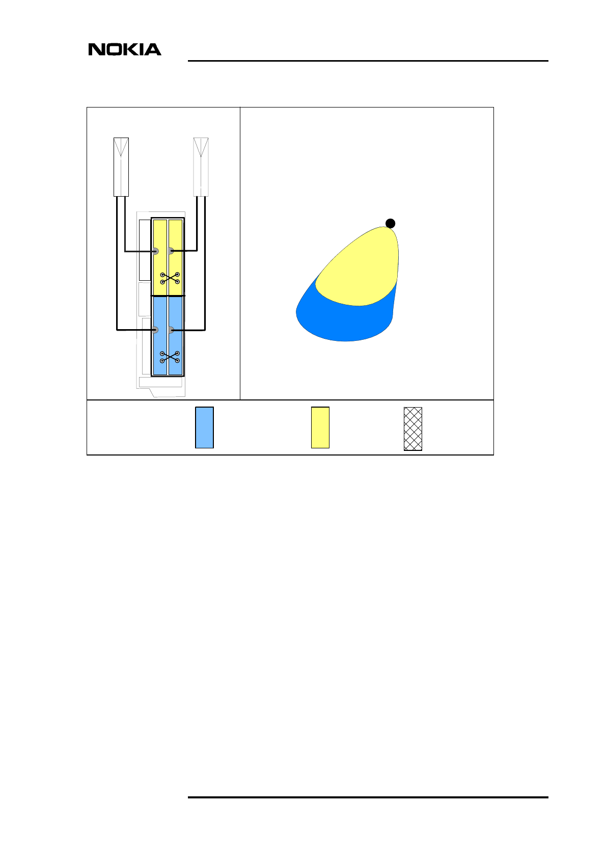
Figure 7 presents a single band (GSM/EDGE 900) BTS which has four TRXs in
one sector. The antennas are directed to the same direction; the resulting coverage
area comprises four TRXs. In order to employ diversity, it is most feasible to
connect the TRXs which share the diversity to different antennas.
Figure 7. Four TRXs in one sector, single band configuration
With dual band antennas, such as the MetroSite antenna, overlapping
GSM/EDGE 900 and GSM/EDGE 1800 coverage areas can be created by
connecting TRXs from a GSM/EDGE 900 sector and TRXs from a GSM/EDGE
1800 sector to one antenna.
Antennas directed to form one coverage area
including 4 GSM/EDGE 900 TRXs.
DIV
OUT
DIV
IN
DIV
IN
DIV
OUT
DIV
OUT
DIV
OUT
DIV
IN
DIV
IN
T
R
X
4
T
R
X
3
T
R
X
2
T
R
X
1
- 4 TRXs
- 1 sector
- Single band
- Diversity
BTS configuration
BTS
Coverage pattern
(principle)
GSM/EDGE 900 = GSM/EDGE 1800 = Dual band =
Product Description
34 (98) © Nokia Corporation Draft DN991444
Nokia Proprietary and Confidential Issue 3-0 en Draft
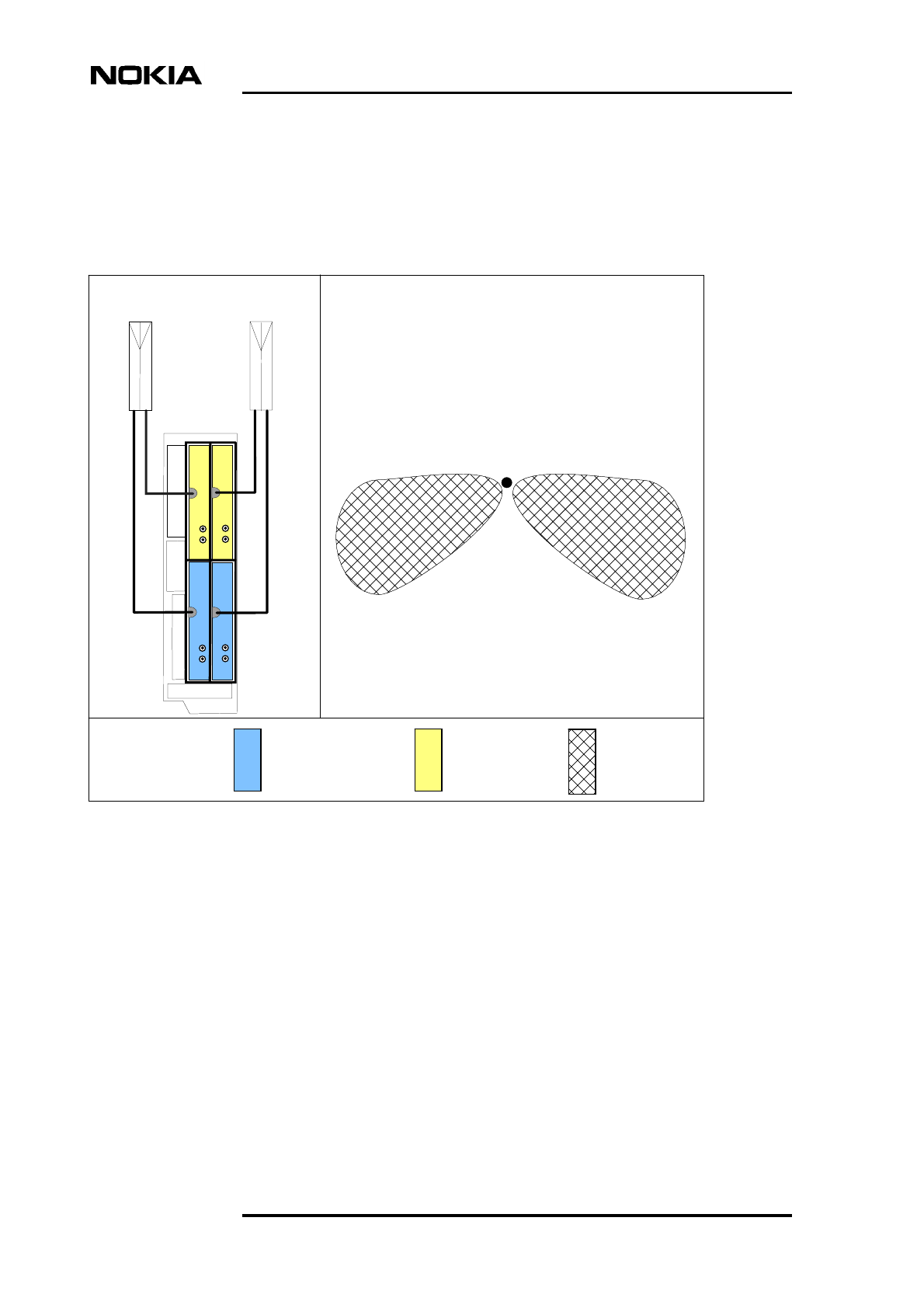
Figure 8 shows schematically the coverage areas created with a BTS that has four
sectors (two GSM/EDGE 900 sectors and two GSM/EDGE 1800 sectors) in a
(1+1)/(1+1) configuration. In Figure 8 , one GSM/EDGE 900 and one
GSM/EDGE 1800 sector are connected to each antenna. The antennas are
directed to different directions.
Figure 8. (1+1)/(1+1) dual band configuration
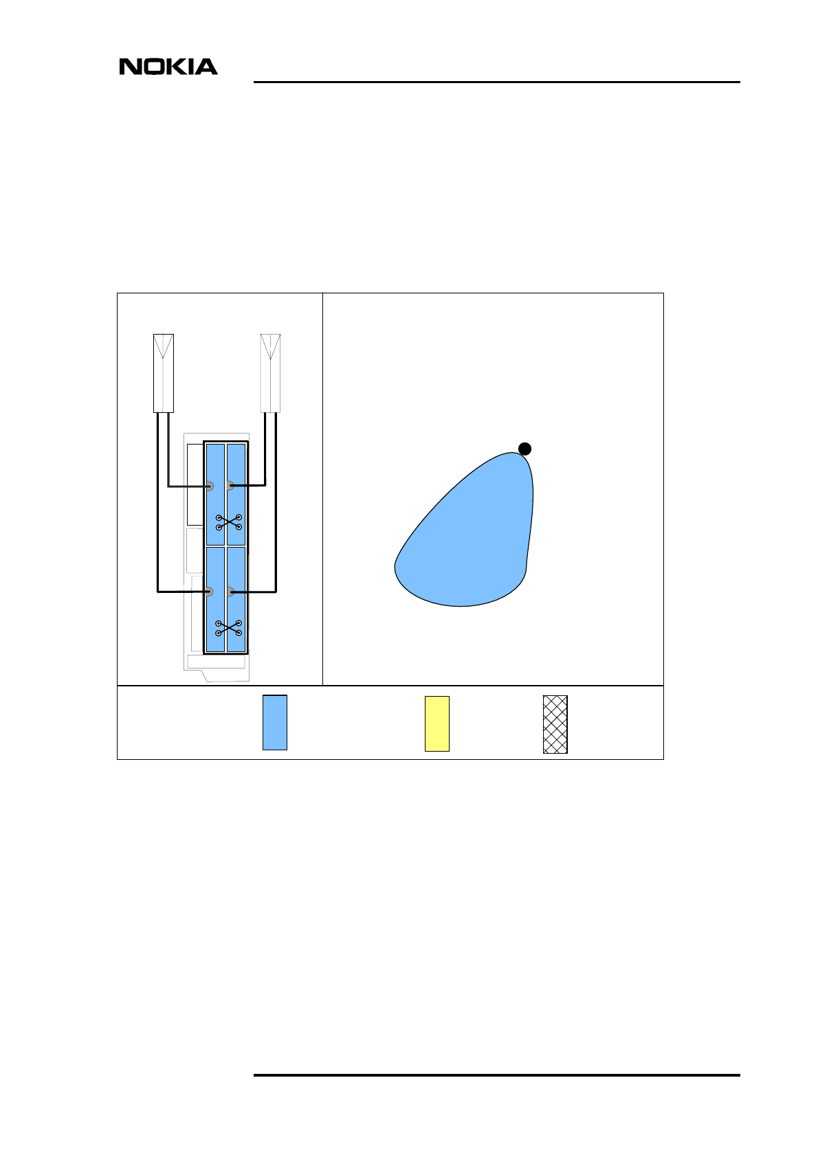
The 2+2 dual band configuration can be used to build one directional dual band
coverage area. This configuration has one GSM/EDGE 900 sector which includes
two TRXs, and one GSM/EDGE 1800 sector also including two TRXs. One TRX
from the GSM/EDGE 900 sector and one TRX from the GSM/EDGE 1800 sector
are connected to one antenna. The antennas are directed to the same direction.
Consequently, the coverage area comprises four TRXs (two GSM/EDGE 900 and
two GSM/EDGE 1800 TRXs). Diversity can also be utilised in this type of
configuration. Figure 9 shows schematically the coverage area built in this
manner.
- (1+1)/(1+1)
TRXs
- Dual band
- No diversity
BTS
Coverage pattern
(principle)
DIV
OUT
DIV
IN
DIV
IN
DIV
OUT
DIV
OUT
DIV
OUT
DIV
IN
DIV
IN
T
R
X
4
T
R
X
3
T
R
X
2
T
R
X
1
BTS configuration
GSM/EDGE 900 = GSM/EDGE 1800 = Dual band =
Antennas directed to form twocoverage areas
1 GSM/EDGE 900 TRX + 1 GSM/EDGE 1800 TRX
in each coverage area
Applications
DN991444 © Nokia Corporation Draft 35 (98)
Issue 3-0 en Draft Nokia Proprietary and Confidential
Figure 9. 2+2 dual band configuration
Another way to build overlapping GSM/EDGE 900 and GSM/EDGE 1800 cells,
is to direct single band GSM/EDGE 900 and GSM/EDGE 1800 antennas towards
the same direction.
The Nokia MetroSite EDGE Base Station can be used to build fill-in coverage in
areas that are difficult to reach with conventional base stations. In these cases, it
is recommended that high-gain antennas are used.
Antennas directed to form one coverage area including
2 GSM/EDGE 900 TRXs + 2 GSM/EDGE 1800 TRXs.
- 2+2 TRXs
- Dual band
- Diversity
Coverage pattern
(principle)
DIV
OUT
DIV
IN
DIV
IN
DIV
OUT
DIV
OUT
DIV
OUT
DIV
IN
DIV
IN
T
R
X
4
T
R
X
3
T
R
X
2
T
R
X
1
BTS configuration
BTS
GSM/EDGE 900 = GSM/EDGE 1800 = Dual band =

Product Description
36 (98) © Nokia Corporation Draft DN991444
Nokia Proprietary and Confidential Issue 3-0 en Draft
Note
4.2 Transmission with the Nokia MetroSite EDGE Base
Station
This section describes the transmission topologies that can be built by using the
transmission unit capacity of the Nokia MetroSite EDGE Base Station. The
transmission node that expands the transmission capacity is typically the Nokia
MetroHub Transmission Node. For more information on the larger
configurations, refer to Nokia MetroHub Transmission Node documentation.
The transmission unit takes care of the transmission between the Nokia MetroSite
EDGE Base Station and the BSC through the Abis interface. The transmission
media can be either radio link (RRI) or wireline (E1/T1).
The FC RRI and FXC RRI transmission units are used with Nokia MetroHopper
radios and/or Nokia FlexiHopper microwave radios. The FC E1/T1, FXC E1 and
FXC E1/T1 transmission units are used for wireline transmission.
When EDGE transmission is being used, the FC type transmission units are not
recommended because of the high data transfer rates that are possible with
EDGE.
The FXC RRI, FXC E1 and FXC E1/T1 transmission units have a cross-connect
capability. The bidirectional connection between two interface ports (B2 cross-
connection) can be made with 2M, nx64k, 64k, 32k, 16k and 8k granularities.
Granularity refers to the number of bits connected into a specific direction in the
cross-connection.
The FC RRI and FC E1/T1 transmission units are used in the termination points
of the transmission chain. More information on transmission unit alternatives can
be found in Chapter 6.
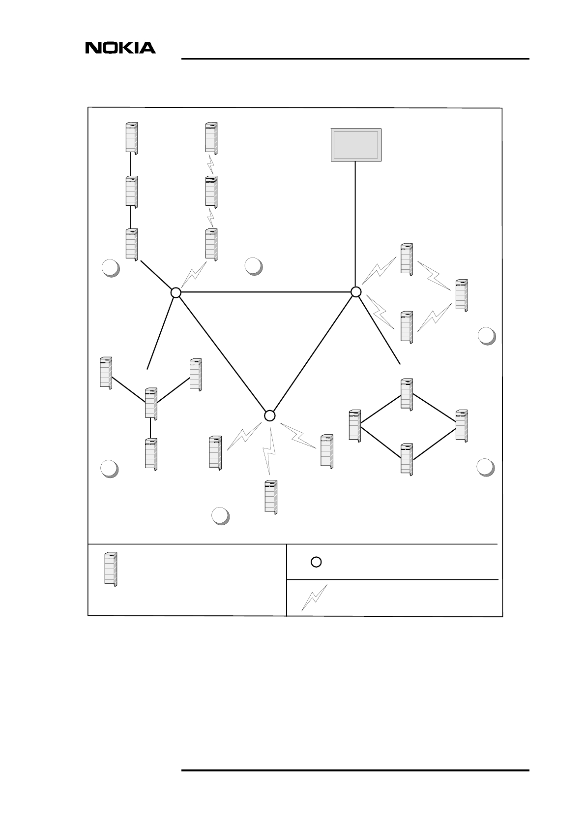
Examples of transmission topologies built with different transmission units are
presented in Figure 10. Depending on the type of transmission unit, it is possible
to use the following network topologies:
• Chain connection (A and B in Figure 10)
• Star connection (C and D in Figure 10; with the radio transmission
alternative, the centre point of the star is always a transmission node)
• Loop connection (E and F in Figure 10)
Applications
DN991444 © Nokia Corporation Draft 37 (98)
Issue 3-0 en Draft Nokia Proprietary and Confidential
Figure 10. Examples of transmission connections
FC E1/T1
FXC E1(/T1)
FXC RRI
FXC RRI
FXC RRI
FC E1(/T1) FC RRI
FXC RRI
FXC RRI
FXC E1(/T1)
FXC E1(/T1)
BSC
FXC E1(/T1)
FXC E1(/T1)
FXC E1(/T1)
n x E1
FXC E1(/T1)
FC E1/T1
FC E1/T1 FC RRI
FC RRI
FC RRI
Transmission node
FXC RRI
Nokia MetroSite BTS with
FXC RRI transmission unit
A
C
B
D
F
E
Radio hop

Product Description
38 (98) © Nokia Corporation Draft DN991444
Nokia Proprietary and Confidential Issue 3-0 en Draft
Note
Furthermore, the Nokia MetroSite EDGE Base Station can be directly connected
to the BSC.
The Nokia MetroSite EDGE Base Station supports 16 Kbit/s, 32 Kbit/s and 64
Kbit/s Abis TRX signalling. The O&M signalling speed alternatives are 16
Kbit/s, 32 Kbit/s and 64 Kbit/s. To optimise the use of transmission capacity,
combined O&M and TRX signalling is also supported at all these speeds.
Locally, the transmission configuration is managed with the Nokia MetroSite
BTS Manager. Information on how to create different transmission
configurations can be found in the MetroSite BTS Manager’s on-line Help.
Since EDGE can carry higher data rates than GSM, the specification of the
transmission unit and its configuration should be of suitably high capacity when
using GSM/EDGE TRXs.

Nokia MetroSite EDGE Base Station related software
DN991444 © Nokia Corporation Draft 39 (98)
Issue 3-0 en Draft Nokia Proprietary and Confidential
5Nokia MetroSite EDGE Base Station
related software
This chapter describes the Nokia MetroSite EDGE Base Station software (SW)
and the Nokia MetroSite BTS Manager software.
Generally, the Nokia MetroSite EDGE Base Station is managed remotely from
the OSS via the BSC. The management tasks carried out on site are kept to a
minimum. On site, the Nokia MetroSite BTS Manager is used for BTS
management.
The Nokia MetroSite EDGE Base Station is delivered to the customer with the
SW pre-installed in order to support rapid deployment of the BTS. The Nokia
MetroSite EDGE Base Station SW is to a large extent based on the SW for the
field-proven Nokia Talk family of base stations and is enhanced with new and
improved features. The new, highly embedded Nokia MetroSite EDGE Base
Station SW makes it possible to upgrade the BTS on-line without interrupting the
BTS operation. Also, the number of alarms sent from the BTS to the BSC is
reduced considerably due to the advanced BTS diagnostics system.
The Nokia OSS incorporates a full range of functions from fault, performance,
and configuration management to transmission and security management and
troubleshooting. For more information, refer to Nokia OSS documentation.
The NMS/2000 SW T13 and BSC SW S10 releases fully support the Nokia
MetroSite EDGE Base Station.
5.1 Nokia MetroSite EDGE Base Station software
The Nokia MetroSite EDGE Base Station can store two SW packages in its non-
volatile memory. The SW can be loaded to the BTS either locally from the Nokia
MetroSite BTS Manager or remotely from the BSC or the NMS/2000. The SW
packages are loaded to the non-volatile memory of each TRX.
The BSC updates the BTS SW packages if they are different from the BSC SW.
After downloading, new SW is activated by reset and the initialisation takes
approximately one minute. The BTS and its units can be reset separately for
testing purposes, locally with the Nokia MetroSite BTS Manager and remotely
from the BSC or the NMS/2000.

Product Description
40 (98) © Nokia Corporation Draft DN991444
Nokia Proprietary and Confidential Issue 3-0 en Draft
The BTS start-up procedure has been optimised to shorten the boot-up time. No
time-consuming tests are done during the BTS start-up, which contributes to rapid
deployment of the BTS and shorter breaks in service after power failures.
Alarms generated by the Nokia MetroSite EDGE Base Station are radically
reduced by advanced diagnostics and alarm management. Only the unit level and
BTS level alarms are sent to the BSC. Correlation rules and fault diagnostic
procedures ensure that the appropriate recovery procedure is activated
automatically. The fault diagnostics make it possible to locate a fault to a specific
unit of the BTS or to a specific part of the BTS system.
5.2 Nokia MetroSite BTS Manager software
Nokia MetroSite BTS Manager is primarily used to commission the BTS and
carry out maintenance tasks locally. BTS sectoring and TRX numbering can be
read from the Nokia MetroSite BTS Manager’s display. During normal operation
the Nokia MetroSite EDGE Base Station is managed remotely from the OSS.
Nokia MetroSite BTS Manager provides a graphical user interface, running in
Windows NT, Windows 95, and Windows 98 environments. The Nokia
MetroSite BTS Manager provides a commissioning wizard software to ease the
process of BTS commissioning. Instructions on how to use the Nokia MetroSite
BTS Manager are given in a context-sensitive on-line Help.
The system requirements for the Nokia MetroSite BTS Manager are detailed in
Table 27.
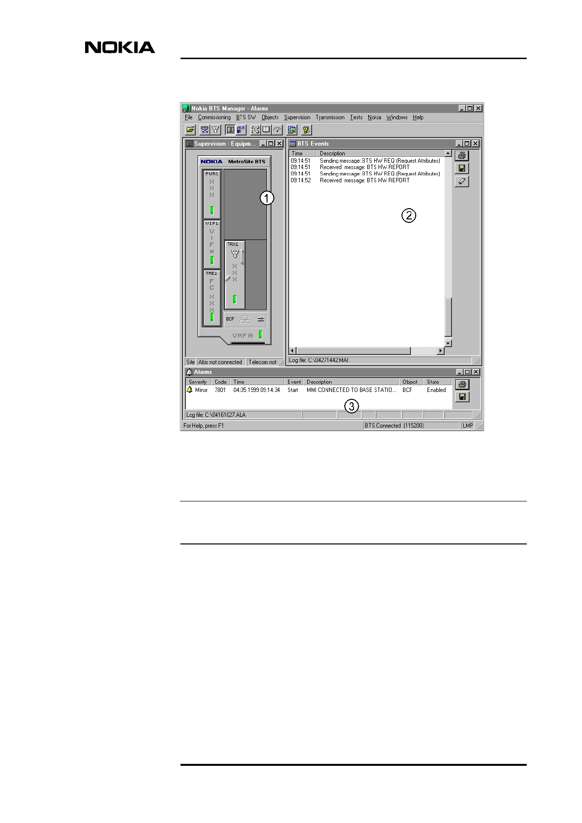
Figure 11 shows an example of the Nokia MetroSite BTS Manager desktop with
the following windows opened:
1. Equipment View in the Supervision window
2. BTS Events window
3. Alarms window
Nokia MetroSite EDGE Base Station related software
DN991444 © Nokia Corporation Draft 41 (98)
Issue 3-0 en Draft Nokia Proprietary and Confidential
Note
Figure 11. Nokia MetroSite BTS Manager desktop
Nokia MetroSite BTS Manager is part of the Nokia SiteWizard SW package.
5.3 BTS software updates
When the Nokia MetroSite EDGE Base Station software is updated, it can be
loaded either locally with the Nokia MetroSite BTS Manager, or remotely from
the BSC or the OSS (via the BSC). The transmission unit software is downloaded
transparently from the network management system (NMS) or locally with Nokia
MetroSite BTS Manager.

Product Description
42 (98) © Nokia Corporation Draft DN991444
Nokia Proprietary and Confidential Issue 3-0 en Draft
The BTS SW is loaded to the master TRX which in turn updates the software in
the slave TRXs. When new TRXs are added for more capacity, or when TRXs are
replaced for maintenance reasons, the master TRX updates the software in the
new slave TRXs if their software version is different from the master TRX SW.
The Nokia MetroSite EDGE Base Station software can be downloaded as a
background operation without interrupting the BTS operation. The activation of
new software causes a short break in service. However, the activation can be done
remotely from the BSC/OSS during the hours of low telecommunication traffic.
For more information refer to the Software Release Binders.
The Nokia MetroSite EDGE Base Station software updates are delivered to the
customer on diskettes which contain the current version of the BTS software. The
Nokia MetroSite BTS Manager is delivered on CD-ROM with Nokia SiteWizard.
For more information on Nokia MetroSite EDGE Base Station SW, refer to Nokia
MetroSite EDGE Base Station software release documentation.

General function, construction and units
DN991444 © Nokia Corporation Draft 43 (98)
Issue 3-0 en Draft Nokia Proprietary and Confidential
6General function, construction and units
This chapter describes the general function, mechanical construction and plug-in
units of the Nokia MetroSite EDGE Base Station.
6.1 Nokia MetroSite EDGE Base Station general
function
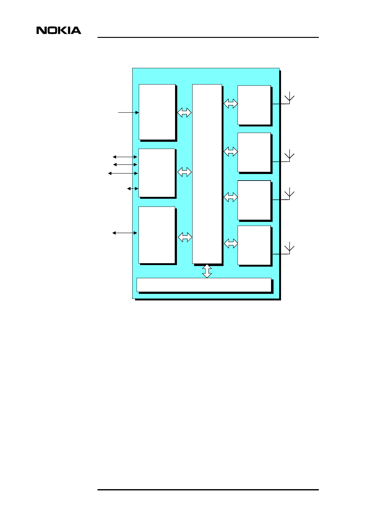
6.1.1 Signalling between network, BTS and MS
The general principle of signalling between the network, the BTS and the Mobile
Station (MS) is presented in Figure 12. A more detailed description of the signal
flow within the Nokia MetroSite EDGE Base Station is presented in Section 6.3.
Product Description
44 (98) © Nokia Corporation Draft DN991444
Nokia Proprietary and Confidential Issue 3-0 en Draft
Figure 12. General principle of signalling between network, BTS and mobile
station
Abis
from
network
Transmission
unit
Abis
to network
BT
S
D-bus TRX
Duplex
filter
Base-
band
TX
RX
TRX
Duplex
filter
Base-
band
TX
RX
TRX
Duplex
filter
Base-
band
TX
RX
TRX
Duplex
filter
Base-
band
TX
RX

General function, construction and units
DN991444 © Nokia Corporation Draft 45 (98)
Issue 3-0 en Draft Nokia Proprietary and Confidential
In the uplink direction, the signal from the MS is picked up by the antennas and
then passes through the duplex filter to the RX part of the transceiver unit. In the
RX part, the signal is converted to the intermediate frequencies (IF) and filtered.
The baseband module performs the digital signal processing and sends the signal
via the D-bus to the transmission unit. The transmission unit connects the BTS via
the Abis interface to the BSC. The Abis interface can be either a cable or radio
link.
In the downlink direction, the signal from the network is submitted via the
transmission unit and D-bus to the baseband module for digital signal processing.
The transmitter part of the transceiver unit receives the modulated baseband
signal from the baseband module, filters the signal to sufficient output spectrum
purity, and raises it to the carrier frequency. The signal goes through the duplex
filter to the antenna; and the antenna sends the signal via the Air interface to the
receiving MS.
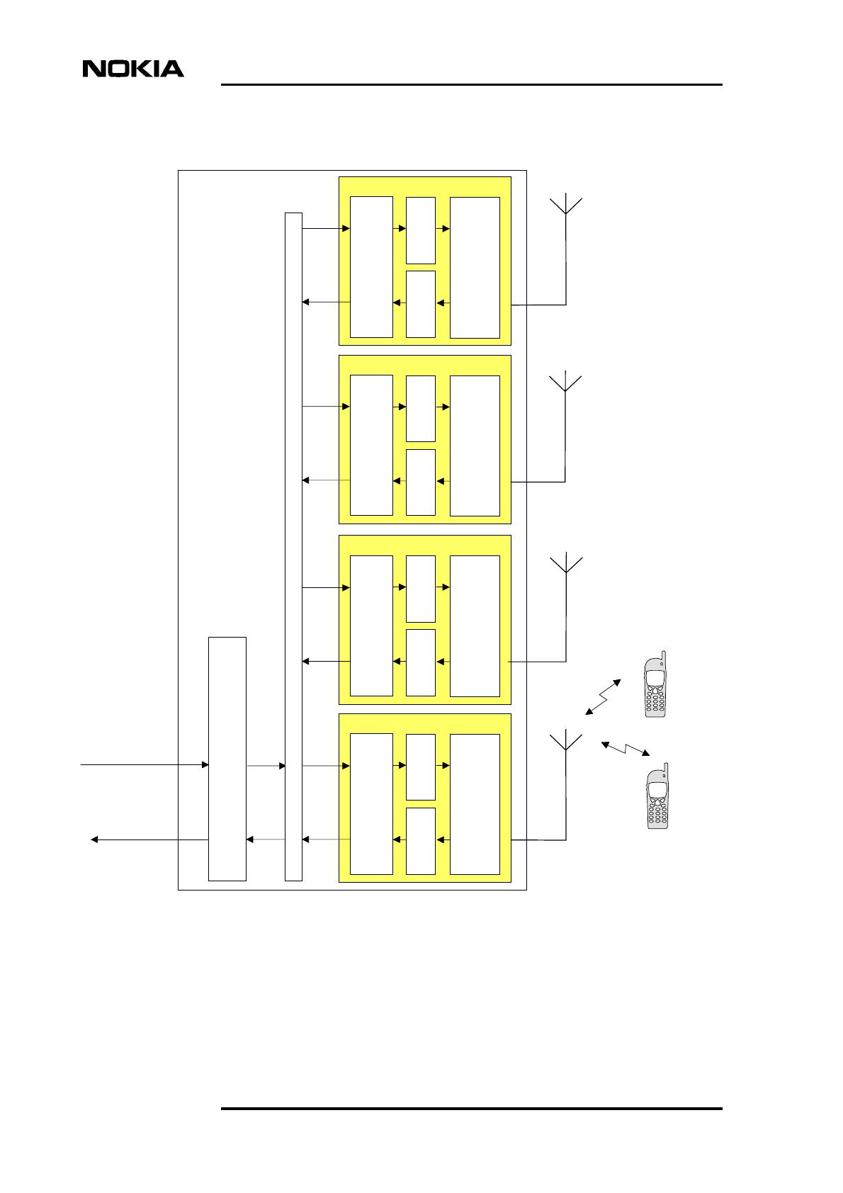
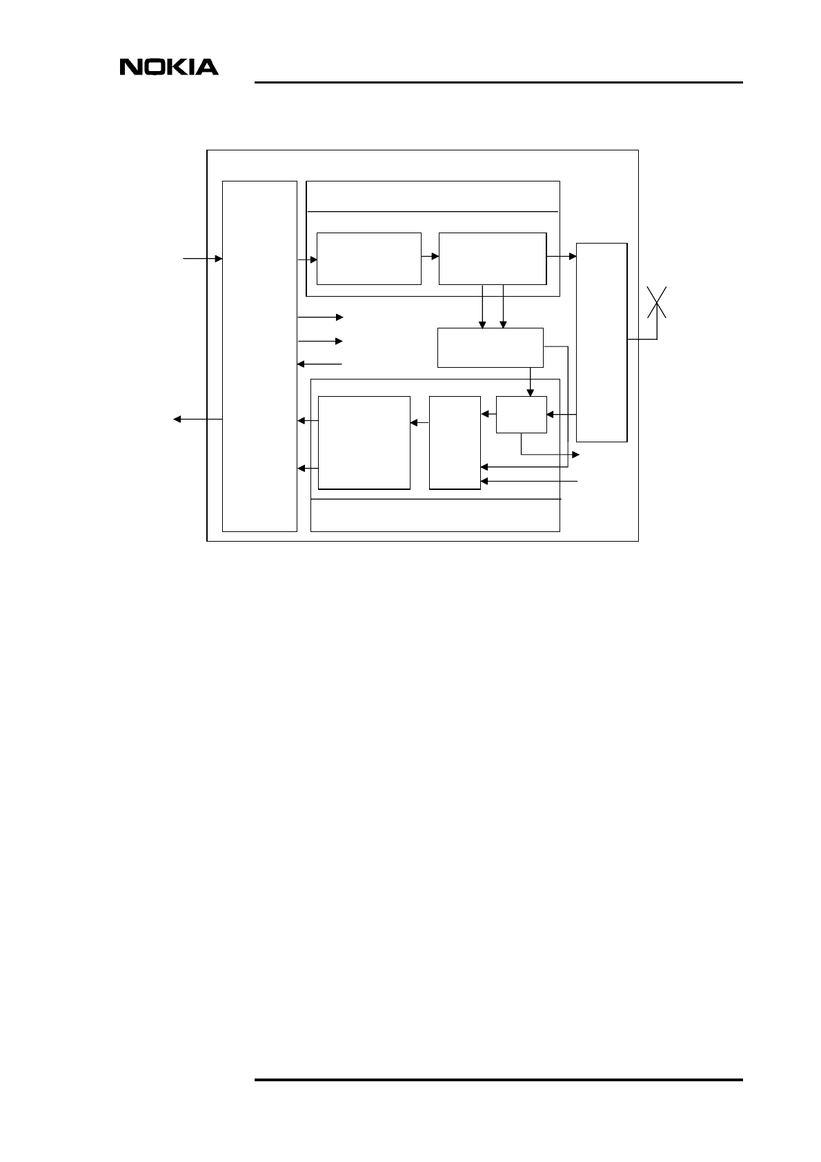
6.1.2 Nokia MetroSite EDGE Base Station internal function
A block diagram of the Nokia MetroSite EDGE Base Station is shown in Figure
13.
Product Description
46 (98) © Nokia Corporation Draft DN991444
Nokia Proprietary and Confidential Issue 3-0 en Draft
Figure 13. Nokia MetroSite EDGE Base Station block diagram
BTS internal buses
The BTS internal signalling and the signalling between the BTS and the adjacent
external equipment is handled by the following buses:
• D1-bus, which handles the data transfer and signalling between the TRX
units and the transmission unit.
• D2-bus, which is the main communication channel between the master
TRX and slave TRXs. Software downloading is handled through the D2-
bus.
• Local Management Bus (LMB), which is used for the BTS and the
transmission units’ control.
Power
supply
Interface
unit Backplane
Nokia MetroSite Base Station
Fan unit
LMP
EAC
Q1
Extension
connection
Abis Transmission
unit
Power
supply
unit
TRX 4
TRX 3
TRX 2
TRX 1

General function, construction and units
DN991444 © Nokia Corporation Draft 47 (98)
Issue 3-0 en Draft Nokia Proprietary and Confidential
• Q1int-bus, which is used for local transmission management.
• Q1-bus, which is used for external equipment management.
• F-bus, which is used for data transfer and signalling between TRX units.
•I
2C-bus (cabinet management bus), which handles the alarm and control
signalling between passive units (all units except for transmission units).
Physically, the buses are located on the BTS backplane.
Base control functions
The Nokia MetroSite EDGE Base Station does not have a separate plug-in unit
for base control functions (BCF) because one of the TRXs is configured as the
master TRX of the BTS. Currently, the master TRX is always located in TRX slot
1 (the lower left TRX slot, next to the transmission unit and interface unit slots).
The following tasks are handled by the master TRX:
• BTS control
• Message delivery to the BSC
• Alarm handling
• Timing functions
• Software downloading
• Self-testing of the BTS
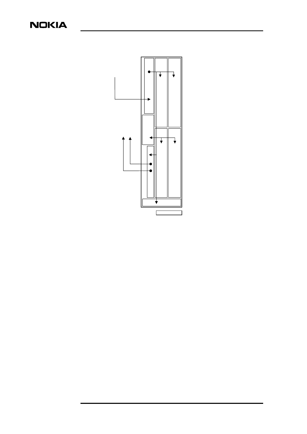
Power distribution
The electrical power (AC or DC) from the external power source is distributed
within the Nokia MetroSite EDGE Base Station by the BTS’s power supply unit.
The power supply unit distributes DC power to the plug-in units. All electrical
connections are conveyed via the backplane. For information on the output
voltages, refer to Section 6.6.2.
The power supply unit is capable of feeding power to the maximum BTS
configuration which includes either two Nokia MetroHopper Radio outdoor units
or two Nokia FlexiHopper Microwave Radio outdoor units.
Product Description
48 (98) © Nokia Corporation Draft DN991444
Nokia Proprietary and Confidential Issue 3-0 en Draft
Figure 14. Power distribution in the Nokia MetroSite EDGE Base Station
6.2 Cabinet (HVMC) and cover (HVCU, WCUA)
Similarly to all the other properties of the Nokia MetroSite EDGE Base Station,
its construction has been optimised for microcellular, building infill and roadside
coverage solutions. The chassis and the units are easy to install and move, and the
compact structure provides new installation possibilities.
The Nokia MetroSite EDGE Base Station features a lightweight aluminium
chassis with a stainless steel sheet metal backplate, aluminium die-cast guides,
and a backplate cover. The Nokia MetroSite EDGE Base Station chassis has a
compact plug-in construction covered by a separate two-tone plastic cover
(coloured light grey NCS-S-2500-N and grey NCS-S-1500-N). If desired, the
cover can be painted so as to better blend into the surrounding environment.
The cover shields the BTS against water, snow or solid foreign objects. The actual
ingress protection and EMC shielding are provided by the chassis and the units.
230 VA
C
or
110 VAC or
+ 24 VDC
- 48 VDC
VSxx
TRX TRX
TRX TRX
VIFA
VMFA
Power outlet for 1-2 radio
outdoor units, 55 VDC
DN99104116

General function, construction and units
DN991444 © Nokia Corporation Draft 49 (98)
Issue 3-0 en Draft Nokia Proprietary and Confidential
An optional WCUA type cover is available. This cover is made from high impact
polycarbonate and when fitted, the Nokia MetroSite EDGE BTS is designed to
meet the requirements for National Equipment-Building Standards (NEBS).
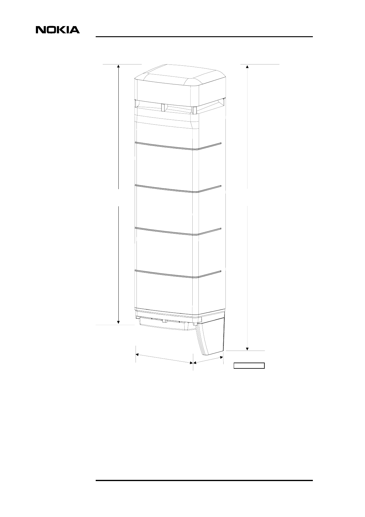
The dimensions of the Nokia MetroSite EDGE Base Station are presented in
Figure 15.
Product Description
50 (98) © Nokia Corporation Draft DN991444
Nokia Proprietary and Confidential Issue 3-0 en Draft
Figure 15. Dimensions of the Nokia MetroSite EDGE Base Station
954 mm
(37.56 in)
871 mm
(34.29 in)
310 mm
(12.20 in)
215 mm
(8.46 in)
DN00286083

General function, construction and units
DN991444 © Nokia Corporation Draft 51 (98)
Issue 3-0 en Draft Nokia Proprietary and Confidential
Note
Plug-in units
The plug-in units are connected to the BTS backplane via the connectors on their
back panels. The following plug-in units have been fitted in the cabinet
mechanics:
• Up to four TRXs
• Interface unit
• Transmission unit
• Power supply unit
• Fan unit
In the following sections, the Nokia abbreviations for different units are given in
the parentheses after the sections’ titles.
The LED conditions of the units are presented in Nokia MetroSite EDGE Base
Station: Maintenance.
Figure 16 shows the arrangement of the units.

Product Description
52 (98) © Nokia Corporation Draft DN991444
Nokia Proprietary and Confidential Issue 3-0 en Draft
Figure 16. Arrangement of units
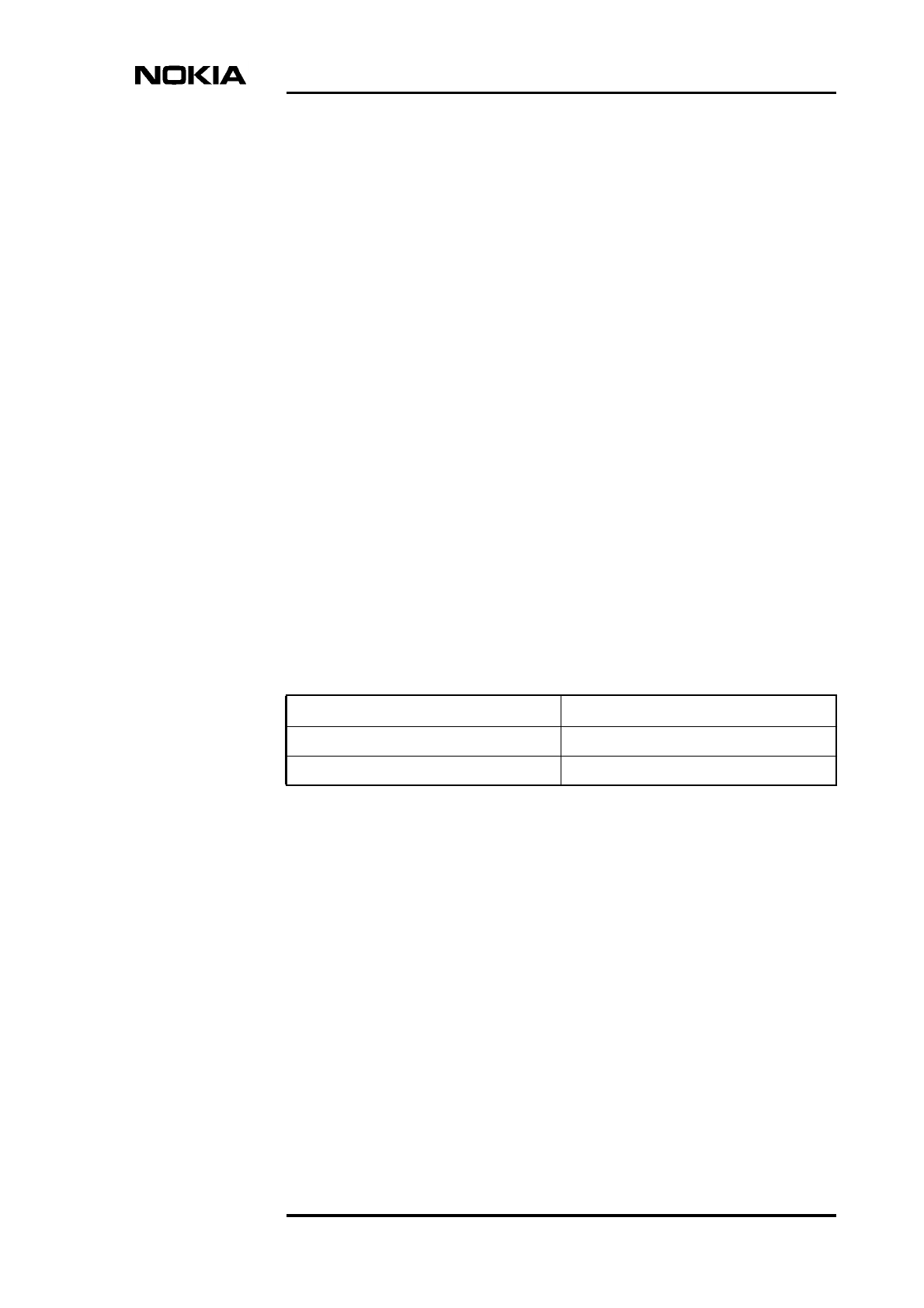
6.3 Transceiver unit (HVTxx and WTxx)
The main function of the transceiver unit (TRX) is to provide the analogue and
digital signal processing required for handling one carrier, both in the uplink (MS
to network) and the downlink (network to MS) direction.
There are 5W (HVTxx) GSM TRX versions available for the 900, 1800, and 1900
MHz frequencies and 5W (WTxx) GSM/EDGE TRX versions available for the
800, 900, 1800, and 1900 MHz frequencies. For a full list of the TRX alternatives,
refer to Table 10.
Cover
Lock
Power supply unit
Interface unit
Transmission unit
Transceiver units
Fan unit
Backplane
General function, construction and units
DN991444 © Nokia Corporation Draft 53 (98)
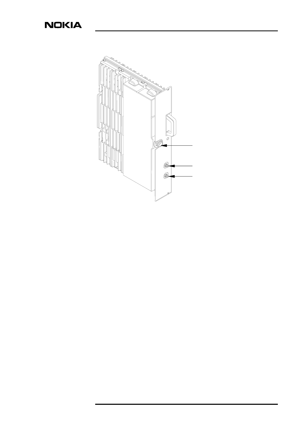
Issue 3-0 en Draft Nokia Proprietary and Confidential
Figure 17. Transceiver unit
The transceiver unit of Nokia MetroSite EDGE Base Station consists of digital
and analogue parts and mechanics. The digital functions are in the baseband
module whereas the analogue part consists of an RF module and integrated
duplex filter.
A block diagram of a Nokia MetroSite TRX is presented in Figure 18.
Antenna connector
Diversity out
Diversity in
Product Description
54 (98) © Nokia Corporation Draft DN991444
Nokia Proprietary and Confidential Issue 3-0 en Draft
Figure 18. Block diagram of a Nokia MetroSite TRX
One of the TRXs is configured as the master TRX, which manages all the O&M
functions of the BTS. In order to optimise the transmitter output power, the
antennas are directly connected to the TRXs.
The nominal transmitter output power at the antenna connector is 5 W (37 dBm
in GMSK, 35 dBm in 8-PSK). The single branch receiver sensitivity is better than
-106.0 dBm for the TCH/FS channel type.
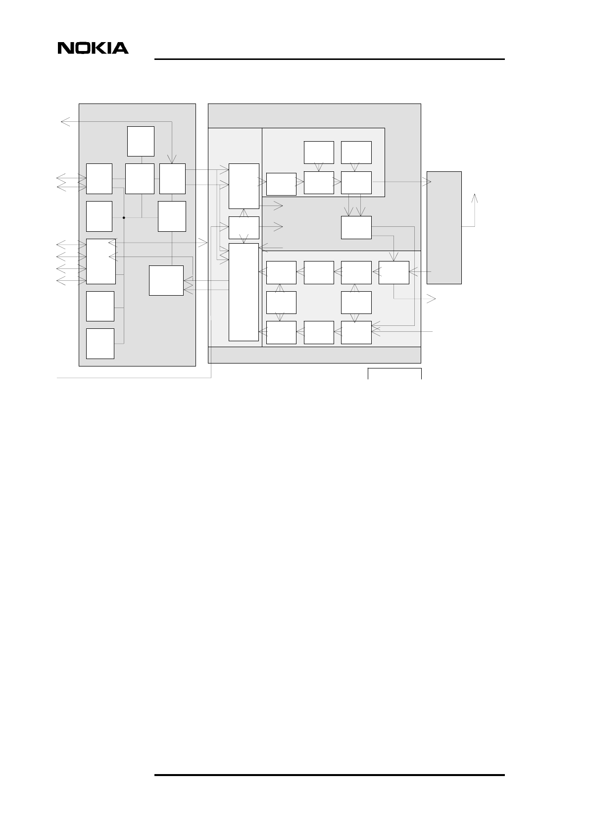
6.3.1 Baseband module
The baseband (BB) module carries out baseband digital signal processing of
speech and data channels and manages all signalling for speech connections. It
also handles software downloading and timing functions of the GSM/EDGE
system.
The block diagram of the baseband module is shown in Figure 19.
RF MODULEBB MODULE
ETXA
TX LO1
IF2
RF
TX FHS
DUPLEX
FILTER
MODULE
MRX
RF
RX
FHS
RX
LO2
MRX
IF2
MRX
IF1
LNA
TRX
LOOP
IF1
ERECVA
REF
OSC
DRX
IF2
DRX
IF1
DRX
RF
ERXA
Fbus
D1E
6.5 M REF
DL
TSCLK
NRX
DRX
RF CONTROL
REF CLOCKS
RF ALARMS
DIV IN
DIV OUT
INTERFACE TRANSMITTER
RECEIVER
ANT
2
D2
EQDSP
EFBIA
SRAM
CHDSP
EDIBA
UC
DRAM
FLASH
EMUCA
UL
I C
2
CLOCKS
I C
LMB
Q1
DN98916275
General function, construction and units
DN991444 © Nokia Corporation Draft 55 (98)
Issue 3-0 en Draft Nokia Proprietary and Confidential
Figure 19. Block diagram of the baseband module
The BB contains the unit controller (UC), two DSPs, four ASICs and memory
circuits.
In the downlink direction, the BB reads the TRAU or PCU frames coming from
the transmission system via the D1E-bus. The data is then processed to GSM
TDMA bit format. Bursts are sent via the downlink serial bus to the RF
transmitter.
In the uplink direction, the BB receives a digital I/Q signal from the RF module
for both main and diversity branches. The samples are combined, detected,
decoded and assembled into TRAU or PCU frames for sending to the Abis
connection.
D-bus
interface RX
TX
F-bus
interface
D1
RX
interface
D2
F-bus
I2CLMP
Q1
Clocks
CH
UC
EQ

Product Description
56 (98) © Nokia Corporation Draft DN991444
Nokia Proprietary and Confidential Issue 3-0 en Draft
The EMUCA ASIC (Application Specific Integrated Circuit) is a UC interface
ASIC. It also handles clock generation and synchronisation, interrupt and alarm
handling functions.
The EQDSP is functionally connected to the ERECVA ASIC. This block handles
sample receiving from RF, channel equalisation and bit detection functions for
both GMSK and 8-PSK.
The interface from the BB to the RF modules is via a serial bus with HDLC
protocol, and contains downlink (DL) data and initialisation messages to the RF
module. The RF to BB HDLC frame includes I (In Phase) and Q (Quadrature)
components of the received signal, and also consists of alarms, timing and status
information from the RF module.
The CHDSP is functionally connected to the EFBIA ASIC. This block handles
burst transmitting to RF (DL_DATA), channel decoding and encoding, and
ciphering and deciphering functions. EFBIA interfaces to the F-bus provide
frequency hopping functions.
The BB contains FLASH and RAM memories. FLASH memory is used for the
BTS SW and SW backup. There are separate RAM memories for the UC and
CHDSP to store programs and data.
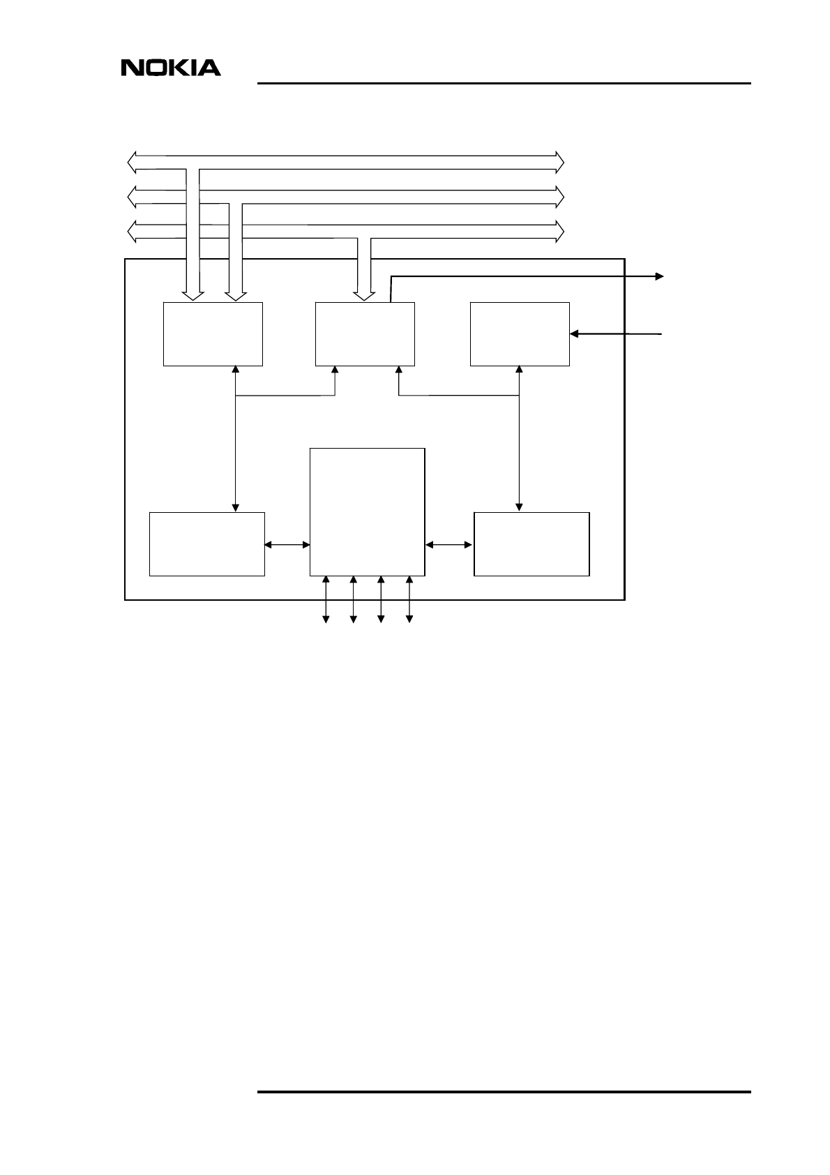
6.3.2 RF module
The RF module has four parts, the TX, RX, RF Loop, and digital interface.
The parts of the RF module are shown in Figure 20.
General function, construction and units
DN991444 © Nokia Corporation Draft 57 (98)
Issue 3-0 en Draft Nokia Proprietary and Confidential
Figure 20. Block diagram of the RF module
Transmitter (TX) part
The transmitter (TX) part includes a Frequency Hopping System (FHS) of its
own, two intermediate frequency blocks, an RF block, and a power control block.
In the TX part the modulation source, Gaussian Minimum Shift Keying (GMSK)
or 8 Phase Shift Keying (8-PSK), is generated in the Direct Digital Synthesis
(DDS) part of the Enhanced Up-converter ASIC (ETXA).
Two stages of up-conversion are used to achieve the carrier frequency. Filters are
used within the chain to achieve spectral purity.
The RF module includes a TX FHS phase-locked synthesizer, for either
frequency hopping between adjacent time slots or providing a fixed frequency
signal in non-hopping mode. The FHS part consists of separate VCO module and
PLL circuits. The TX FHS provides the local oscillator signal in the final up-
conversion stage of the TX chain.
RF module
RF
Duplex
filter
RF
section
IF sections LNA
TRX
loop part
IF sections
Downlink
RF control
REF clocks
RF alarms
DIV IN
DIV OUT
Interface
to
baseband
module
ANT
RX synthesisers
TX synthesisers
TX part
RX part
Uplink

Product Description
58 (98) © Nokia Corporation Draft DN991444
Nokia Proprietary and Confidential Issue 3-0 en Draft
Receiver (RX) part
The receiver (RX) part includes a common LNA, FHS and the second LO. The
RF block, two intermediate frequency blocks and AGC are separate for the main
and diversity branches.
The LNA amplifies the signal for the main RX branch and provides diversity
output for the other TRX. The diversity input from the other TRX is fed to the first
mixer of the diversity branch.
The RX paths convert the input signals from the duplex filtering module by
double down-conversion to a final intermediate frequency (IF). Analogue
filtering and an on/off type AGC are included in the first IF. The variable gain
block in the second stage prevents compression by keeping the signal level within
the dynamic range of the output A/D convertor. The signal from the A/D
converter is passed to the Enhanced Down-converter ASIC (ERXA), where
decimation and channel filtering occur. The main and diversity digital signals are
then sent to the BB for DSP processing.
The RF module includes an RX FHS phase-locked synthesizer, for either
frequency hopping between adjacent time slots or providing a fixed frequency
signal in non-hopping mode. The FHS part consists of separate VCO module and
PLL circuits. The RX FHS provides the local oscillator signal in the first down-
conversion stage of both RX chains.
The RX part also provides the local oscillator (LO) for the RX IF sections.
RF Loop part
The RF loop part provides transceiver test loop and antenna monitoring facilities.
The LED display is also included in this part.
The RF loop converts the TX RF signal down to RX frequency. The down-
converted TX signal can be selected as an incident or reflected signal to facilitate
antenna monitoring.
The down-converted signal is coupled to the input of the LNA and input to the
diversity branch mixer. The three time slot delay and BER test are performed by
the DSP SW for both GMSK and 8-PSK.
There is also a reflected power measurement circuit that raises an alarm when the
antenna connector is left open at full power.
Digital part
The digital section of the RF module include two ASICs. These interface to the
BB and provide control and reference signals to, and alarms from, the analogue
functions of the RF module. The Enhanced Up-converter ASIC (EXTA)
incorporates a DDS, generating a modulated signal for the TX. The Enhanced
Down-converter ASIC (ERXA) performs digital channel filtering and controls
AGC.
General function, construction and units
DN991444 © Nokia Corporation Draft 59 (98)
Issue 3-0 en Draft Nokia Proprietary and Confidential
In addition to the DDS and power control functions, the ETXA provides the
controls for all TRX synthesisers. TRX and antenna loop controls are also
provided by the ETXA and from the BB via the I2C bus. Time or state dependent
alarms are collected and fed on to the ERXA.
The digital interface includes a PLL part to generate clocks needed for ASICs and
FHSs.
Duplex filter part
The passive duplex filter is connected to the RF module and has a single antenna
connector. There are also customer specific filter modules available for the 900
MHz frequency band.
Mechanics
The mechanics provide an electrical and environmental shield for the unit. In
addition, at higher ambient temperatures it acts as a heat sink, conducting the
dissipated heat out of the units, and at lower ambient temperatures it acts as a
heater.
6.3.3 External interfaces
The front panel interface connectors are described in Table 2.
6.4 Interface unit (VIFA)
The external interfaces of the Nokia MetroSite EDGE Base Station are located on
the interface unit. The Local Management Port (LMP) provides the connection to
the MetroSite BTS Manager PC. The Nokia Q1 interface is a connection for
supervising the Nokia Q1-bus compatible external equipment, such as DMR
radios. The extension interface is used as a databus for BTS chaining.
Furthermore, the interface unit provides connections for ten customer-definable
external alarms and four controls.
The interface unit contains the reference clock source of the BTS that is tuned by
the master TRX, based on transmission or external synchronisation interfaces.
Table 2. TRX interface connectors
Connector Type
Antenna N (female)
2 x RX diversity (In/Out) SMA (female)
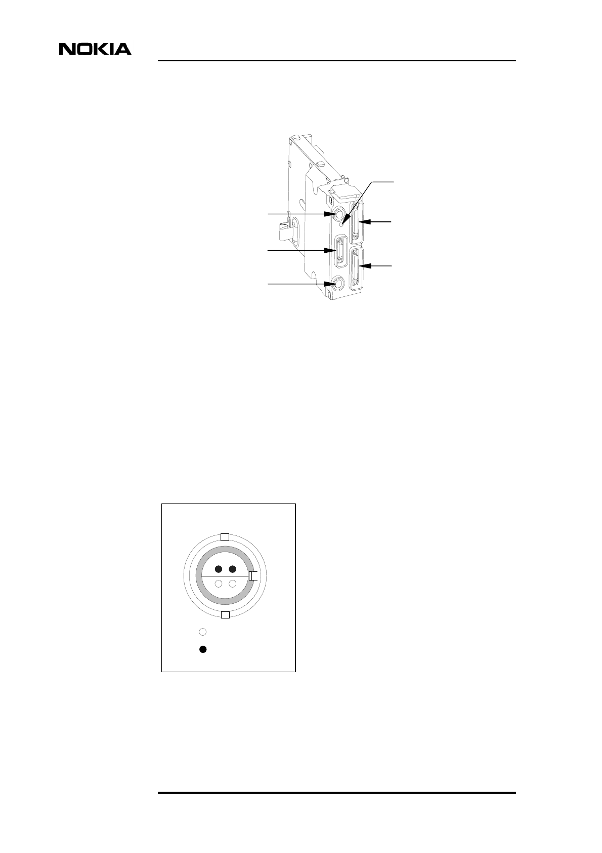
Product Description
60 (98) © Nokia Corporation Draft DN991444
Nokia Proprietary and Confidential Issue 3-0 en Draft
The door switch and test interfaces are located at the side of the interface unit.
Figure 21. Interface unit of the Nokia MetroSite EDGE Base Station
6.4.1 External interfaces
The interfaces and their connector types are described in this section.
Local Management Port (LMP)
The LMP provides the connection to the MetroSite BTS Manager PC. The
connector type for the LMP is BQ, RS-232. Figure 22 and Table 3 present the pin
order and configuration for the LMP connector.
Figure 22. Pin order of the LMP connector
Extension interface
Extension interface
Local management
port (LMP)
External alarms
and controls
Nokia Q1 interface
LED indication
LMP
43
1
2
= Hole
= Pin
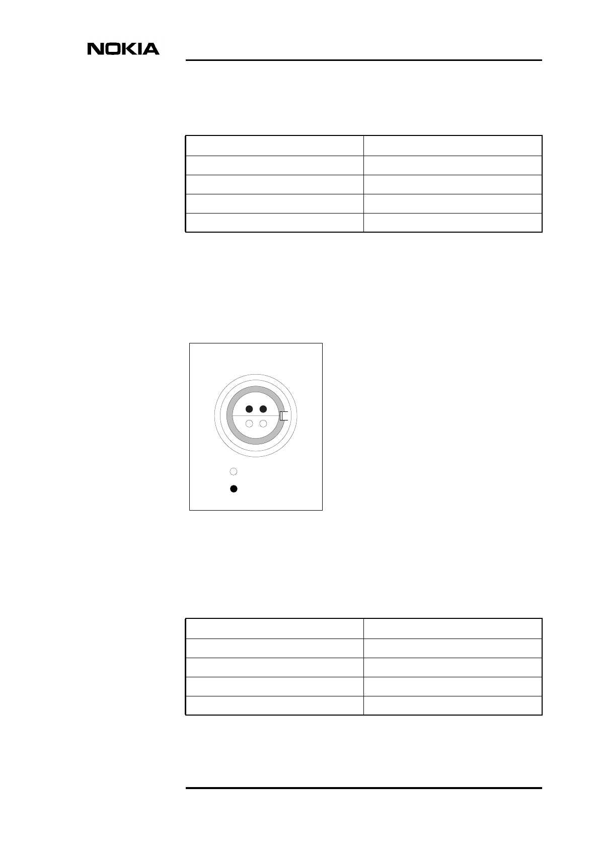
General function, construction and units
DN991444 © Nokia Corporation Draft 61 (98)
Issue 3-0 en Draft Nokia Proprietary and Confidential
Nokia Q1 interface
The Nokia Q1 interface provides a connection for supervising the Nokia Q1-bus
compatible external equipment, such as DMR radios. The Q1 interface connector
type is TQ. Figure 23 and Table 4 present the pin order and configuration for the
Q1 connector.
Figure 23. Pin order of the Q1 connector
Table 3. Pin configuration of the LMP connector
Pin number Signal
1 LMP in
2 +5 V
3 LMP out
4 Ground
Q1
43
1
2
= Hole
= Pin
Table 4. Pin configuration of the Nokia Q1 connector
Pin number Signal
1 Q1 in+
2 Q1 in-
3 Q1 out+
4 Q1 out-
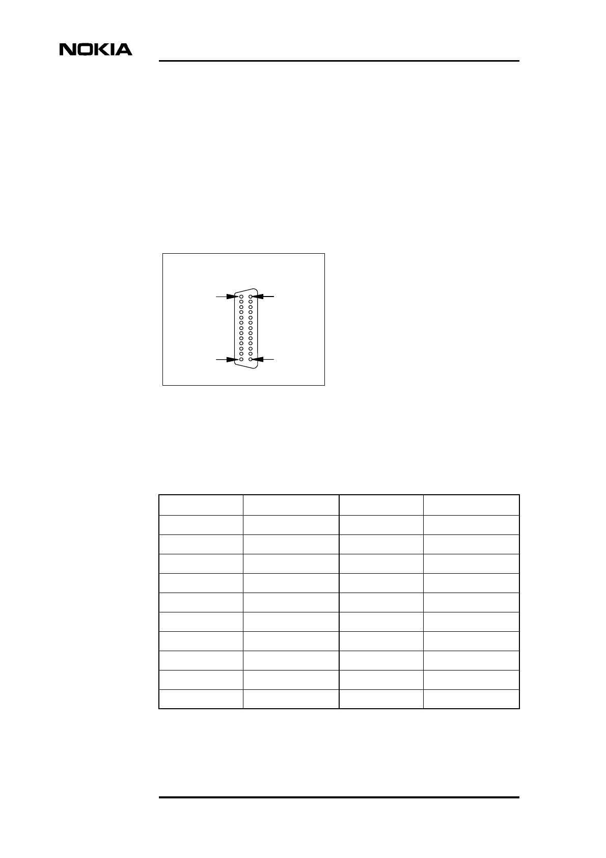
Product Description
62 (98) © Nokia Corporation Draft DN991444
Nokia Proprietary and Confidential Issue 3-0 en Draft
Extension interface
This 50-pin mini D-type connector is used for BTS chaining and for connecting
to the Nokia MetroHub Transmission Node.
External alarms and controls (EAC)
The external alarms and controls connector provides the interface for 10 customer
definable external alarm (EA) inputs and 4 control outputs (ECO). The connector
type is the 26-pin mini D-type connector (female). Figure 24 and Table 5 present
the pin order and configuration of the EAC connector.
Figure 24. Pin order of the EAC connector
pin 1
pin 13pin 26
pin 14
EAC
Table 5. Pin configurations of the EAC connector
Pin number Signal Pin number Signal
1 EA1 14 GND
2 EA2 15 GND
3 EA3 16 GND
4 EA4 17 GND
5 EA5 18 GND
6 EA6 19 GND
7 EA7 20 GND
8 EA8 21 GND
9 EA9 22 GND
10 EA10 23 GND

General function, construction and units
DN991444 © Nokia Corporation Draft 63 (98)
Issue 3-0 en Draft Nokia Proprietary and Confidential
6.5 Transmission unit (VXEA, VXTx, VXRB)
This section provides the technical information on the transmission units used in
the Nokia MetroSite EDGE Base Station. The different transmission
configurations that can be built with the transmission units described here are
presented in Chapter 4. For the transmission interface protocols and standards
refer to Section 8.4.5 of this document.
All transmission units can be managed locally with the Nokia SiteWizard
software.
6.5.1 Unit alternatives for radio link transmission
The following radio link transmission units are available for the Nokia MetroSite
EDGE Base Station:
FXC RRI (VXRB)
• Maximum 16 x 2 Mbit/s capacity
• Support for two microwave radio outdoor units (two TNC connectors)
• Grooming, branching and loop protection support
• Cross-connection at 8 Kbit/s level
FXC RRI transmission units are used with Nokia MetroHopper Radio and Nokia
FlexiHopper microwave radio. For more information on the radios and
transmission units, refer to Nokia MetroHopper Radio Product Description and
Nokia FlexiHopper microwave radio Product Description. The transmission unit
is connected to the Nokia MetroHopper Radio with a single coaxial cable,
referred to as Flexbus (FB). For more information on Flexbus, refer to Chapter 8 ).
11 ECO1 24 ECO3
12 +3 V 25 ECO4
13 ECO2 26 +5 V
Table 5. Pin configurations of the EAC connector (Continued)
Pin number Signal Pin number Signal
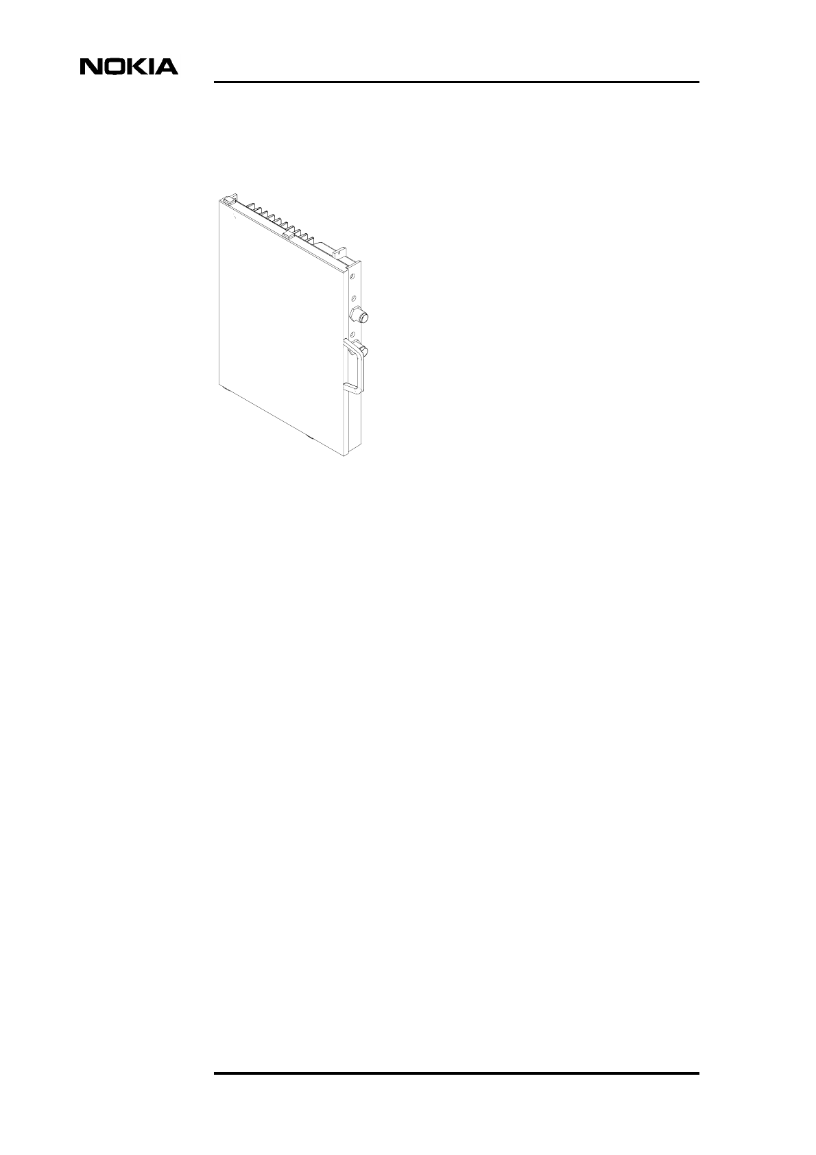
Product Description
64 (98) © Nokia Corporation Draft DN991444
Nokia Proprietary and Confidential Issue 3-0 en Draft
Figure 25. Radio link transmission unit alternatives
6.5.2 Unit alternatives for wireline transmission
The following wireline transmission units are available for the Nokia MetroSite
EDGE Base Station:
FC E1/T1 (VXEA)
The FC E1/T1 transmission unit:
• Provides one Abis line interface to the 2 Mbit/s (E1) or 1.5 Mbit/s (T1)
transmission line
• Operates as the termination point in a chain or star configuration
• Has no cross-connection capability
On its front panel, the FC E1/T1 has two unbalanced interface connectors
(separate TX and RX connectors) for the 75 Ω E1 interface. The TX and RX
connectors are connected to each other with a grounding bridge. By removing the
grounding bridge, the RX connector’s outer conductor can be changed from direct
grounding to capacitive grounding.
There is also one balanced connector, which can be configured to be a 120 ΩE1
interface or 100 Ω T1 interface. The balanced connector offers both the TX and
RX direction. The pin order and pin configuration of the balanced TQ connector
are presented in Figure 26 and in Table 6.
FXC RRI
FB2
FB1
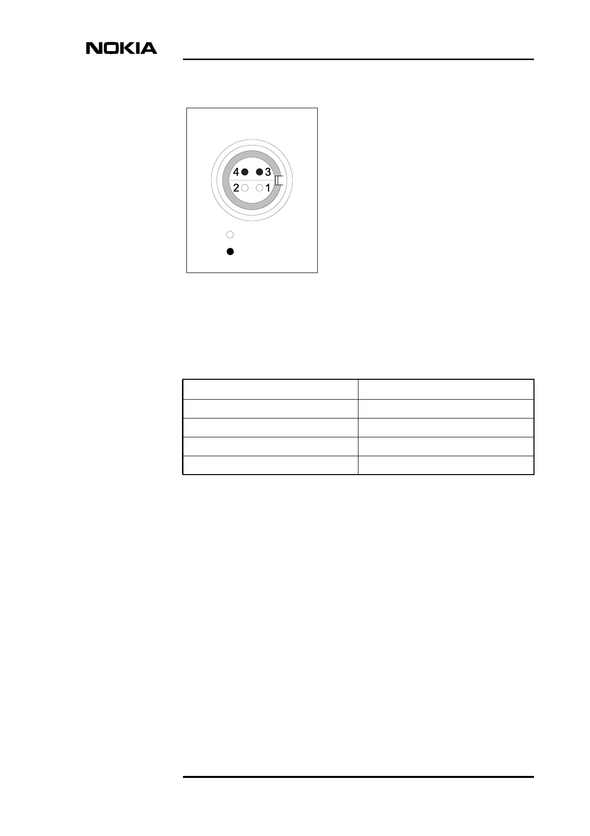
General function, construction and units
DN991444 © Nokia Corporation Draft 65 (98)
Issue 3-0 en Draft Nokia Proprietary and Confidential
Figure 26. Pin order of a balanced TQ connector
FXC E1 (VXTA)
In addition to digital speech data, the FXC E1 transmission unit can also transfer
operating and maintenance information to other equipment in the network.
The FXC E1 offers the following main features:
• Four Abis line interfaces to the 2 Mbit/s (E1) transmission line
• Grooming, branching and loop protection support
• 8 Kbit/s level cross-connection functions between the four Abis line
interfaces and the D-bus
• Nokia Q1 E2E traffic routing model, which allows easy transmission
network planning
= Hole
= Pin
TQ
Table 6. Pin configuration of a balanced TQ connector
Pin number Signal
1 RX+
2 RX-
3 TX+
4 TX-

Product Description
66 (98) © Nokia Corporation Draft DN991444
Nokia Proprietary and Confidential Issue 3-0 en Draft
The front panel of the FXC E1 has four pairs of unbalanced BT-43 interface
connectors (separate TX and RX connectors) for the 75 Ω E1 interface. The TX
and RX connectors are connected to each other with a grounding bridge. By
removing the grounding bridge, the RX connector’s outer conductor can be
changed from direct grounding to capacitive grounding.
For more information on the FXC E1 transmission unit, refer to Nokia MetroHub
Product Description.
FXC E1/T1 (VXTB):
In addition to digital speech data, the FXC E1/T1 transmission unit can also
transfer operating and maintenance information to other equipment in the
network.
FXC E1/T1 offers the following main features:
• Four Abis line interfaces to the 2 Mbit/s (E1) or 1.5 Mbit/s (T1)
transmission line
• Grooming, branching and loop protection support
• 8 Kbit/s level cross-connection functions between the four Abis line
interfaces and the D-bus
• Nokia Q1 E2E traffic routing model, which allows easy transmission
network planning
The front panel of FXC E1/T1 has four balanced TQ connectors (for pin order and
configuration see Figure 26 and Table 6). The connectors offer both TX and RX
direction. Each line interface can be independently configured to be a 120 Ω E1
interface or 100 Ω T1 interface, which enables using the balanced FXC E1/T1
unit as an E1/T1-converter.
For more information on the FXC E1/T1 transmission unit, refer to the Nokia
MetroHub Transmission Node Product Description.
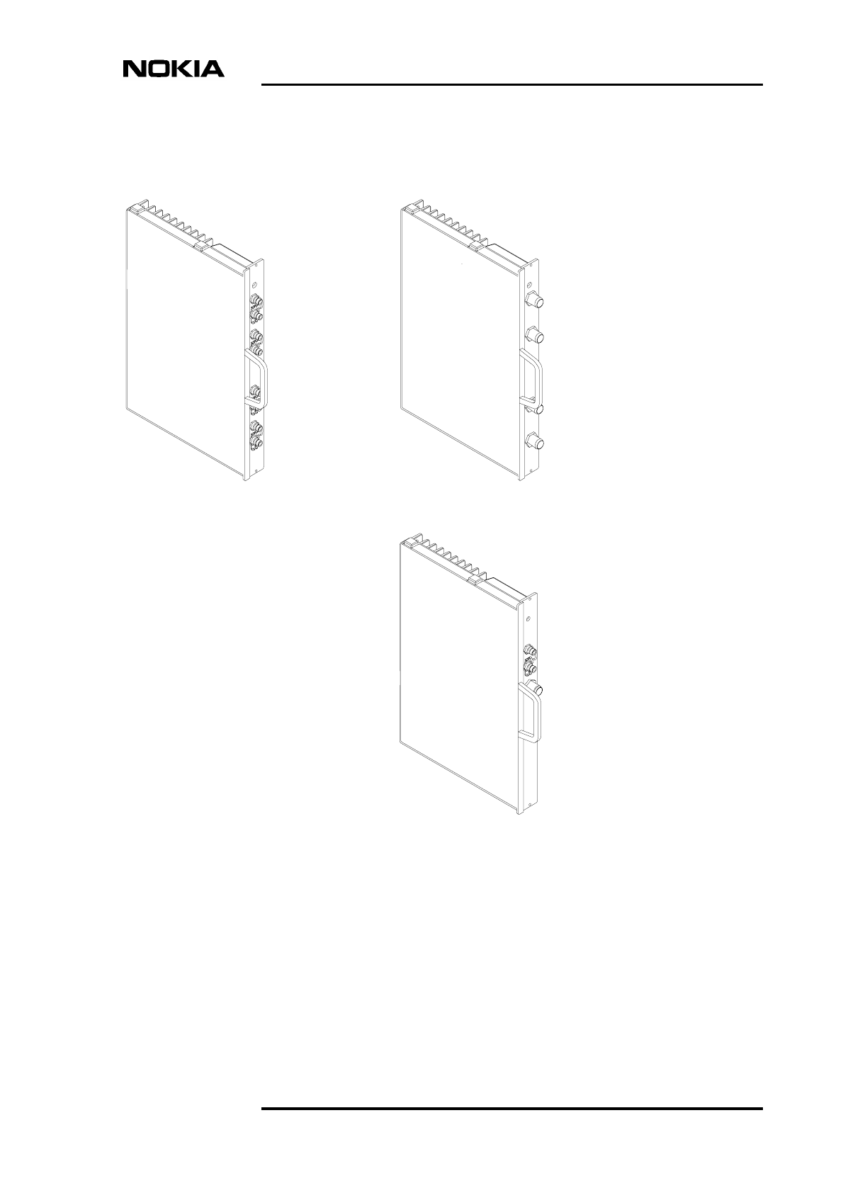
General function, construction and units
DN991444 © Nokia Corporation Draft 67 (98)
Issue 3-0 en Draft Nokia Proprietary and Confidential
Figure 27. Wireline transmission unit alternatives
FXC E1
(unbalanced) FXC E1/T1
(balanced)
FC E1/T1
IF1 TX/RX
IF2 TX/RX
IF3 TX/RX
IF4 TX/RX
IF1 TX
IF1 RX
IF2 TX
IF2 RX
IF3 TX
IF3 RX
IF4 TX
IF4 RX
IF TX
IF RX
IF TX/RX
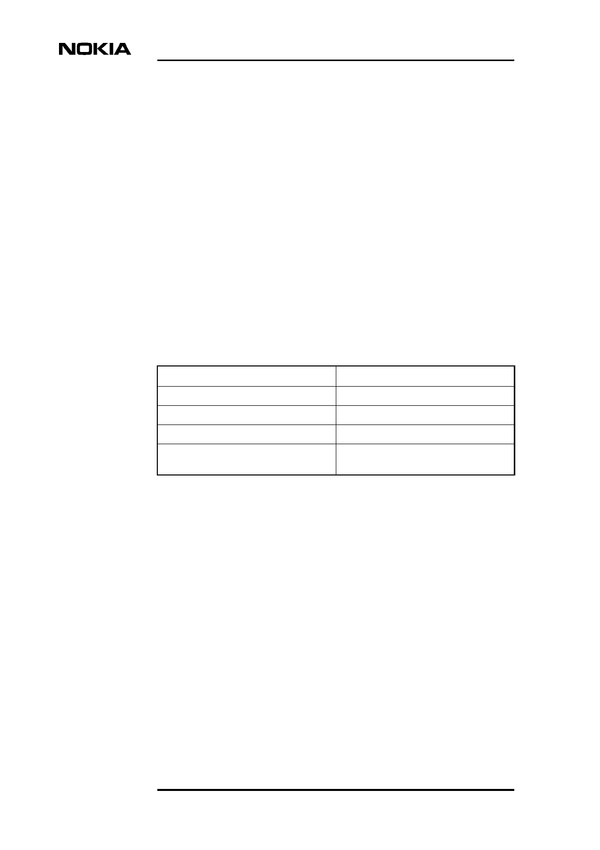
Product Description
68 (98) © Nokia Corporation Draft DN991444
Nokia Proprietary and Confidential Issue 3-0 en Draft
6.6 Power supply unit (HVSx)
The purpose of the power supply unit is to convert the incoming AC or DC supply
voltages into the appropriate DC output voltages. The power is distributed to the
units of the Nokia MetroSite EDGE Base Station and to radio outdoor units (if
used) via the backplane. DC power supplies are reverse polarity protected.
In the case of mains power failure, the AC power supply unit provides a backup
time of 130 ms during which the alarm can be sent. The alarm signal appears
when the input voltage drops below the specified limit. The limit is dependent on
the power supply unit type.
6.6.1 Power supply unit alternatives
The power supply units alternatives available for the Nokia MetroSite EDGE
Base Station are listed in Table 7.
6.6.2 Output voltages
The output voltages from the power supply unit are the following:
• +3.4 VDC, +5.1 VDC, -5.1 VDC, +9.1 VDC, -9.1 VDC, +26.2 VDC and
+55 VDC
• 24 VDC for fan unit
When the fan unit is not in use, the same output voltage feeds power to the heater.
The output voltage to the fan unit and heating is controlled by the I2C-bus. The
heating voltage is controlled in five steps ranging from 0 VDC (no heating) to 24
VDC (full heating), the intermediate voltages being 7.2 VDC, 10.9 VDC and 14.7
VDC.
DC power supplies are reverse polarity protected.
Table 7. Power supply unit alternatives
Input voltage PSU type
230 VAC HVSA
110 VAC HVSB
-48 VDC HVSD
+24 VDC HVSC (available for the 800 and 1900
MHz BTS)
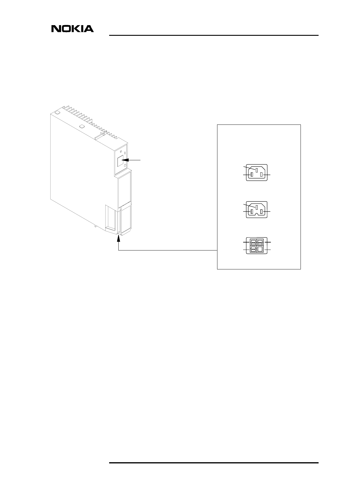
General function, construction and units
DN991444 © Nokia Corporation Draft 69 (98)
Issue 3-0 en Draft Nokia Proprietary and Confidential
6.6.3 Connector types
All alternative power supply units have the same physical appearance. The power
input connector types, however, are different. The power supply unit and the three
connector types are shown in Figure 28.
Figure 28. Power supply unit
The connector type of each power supply alternative is presented in Table 8.
AC 230 V
AC 110 V
DC
Main power switch
with two positions:
ON and stand-by
Connector alternatives:
1
23
1
23
2
3
1
4

Product Description
70 (98) © Nokia Corporation Draft DN991444
Nokia Proprietary and Confidential Issue 3-0 en Draft
6.7 Fan unit (HVMF)
The fan unit is located at the bottom of the cabinet. The master TRX controls the
fan unit via I2C-bus according to temperature information from other units. The
cooling is performed by adjusting the rotation speed of the fan. The adjustable
speed also minimises the noise generated by the fan unit. The fan unit has 16
speeds.
One cooling fan unit is available, applicable for all MetroSite TRX variants. The
fan details are given in Table 9 and is shown in Figure 29.
Table 8. Power supply connector types
Power supply
type Connector type Pin configuration
230 VAC IEC 320 (male) 1 = Ground (E)
2 = Neutral (N)
3 = Live (L)
110 VAC IEC 320 (male) with a
notch
1 = Ground (E)
2 = Live 2 (L2)
3 = Live 1 (L1)
-48 VDC Anderson Power pole 1 = Ground
2 = Positive input, +36 to +60 VDC,
permitted fluctuation ±20% (or positive
input 0 V)
3 = Negative input, 0 V (or negative
input -36 to -60 VDC, permitted
fluctuation ±20%)
4 = spacer
+24 VDC Anderson Power pole 1 = Ground
2 = Positive input, 0 V (or +20 to +28
VDC, permitted fluctuation ±20%)
3 = Negative input, -20 to -28 VDC,
permitted fluctuation ±20% (or negative
input 0 V)
4 = spacer
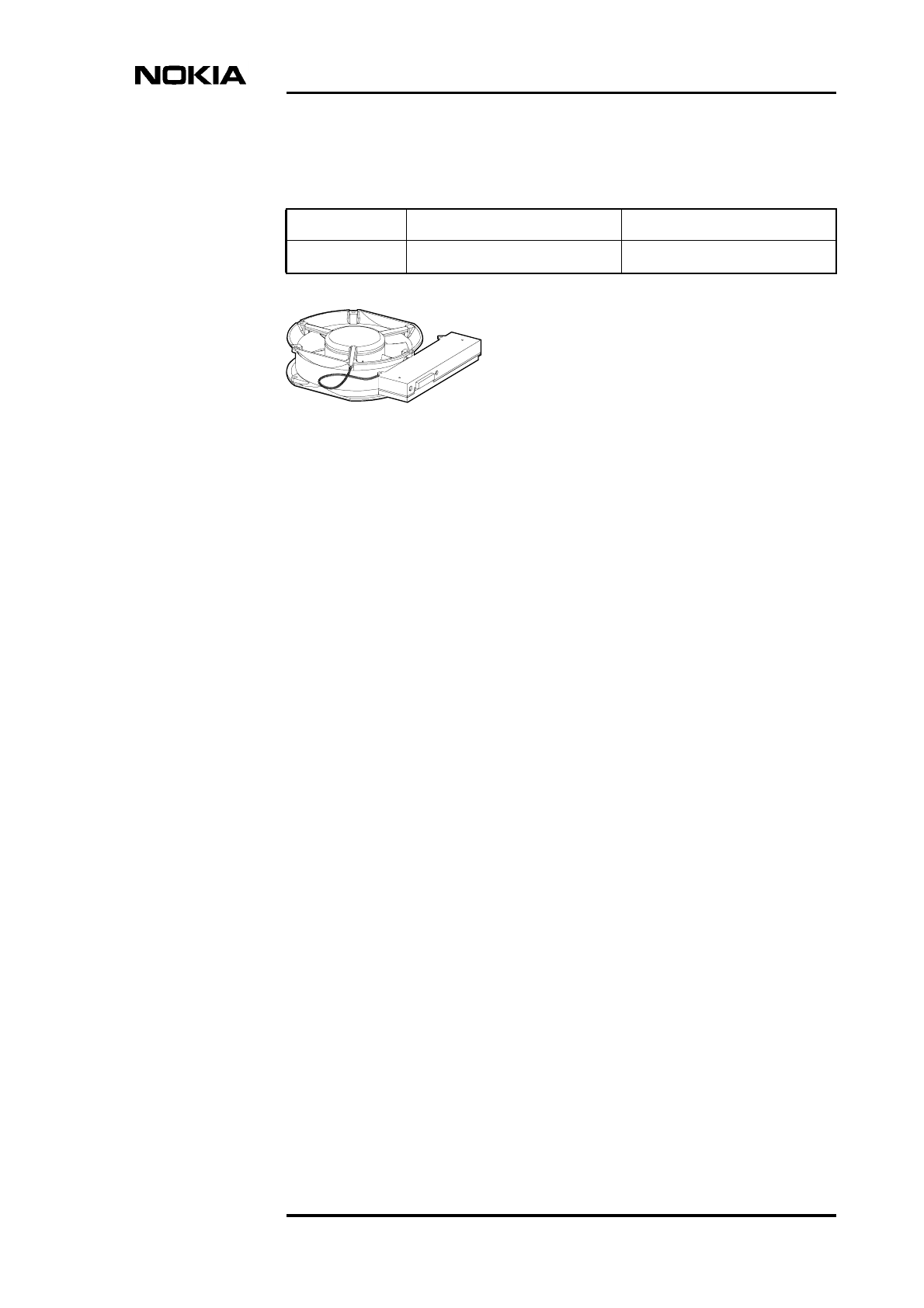
General function, construction and units
DN991444 © Nokia Corporation Draft 71 (98)
Issue 3-0 en Draft Nokia Proprietary and Confidential
Figure 29. Fan unit
Table 9. Cooling fans details
Fan type Cooling fan capacity Notes
HVMF 120 m3/hr (4238 ft3/hr) For all MetroSite BTS TRXs
HVMF

Product Description
72 (98) © Nokia Corporation Draft DN991444
Nokia Proprietary and Confidential Issue 3-0 en Draft
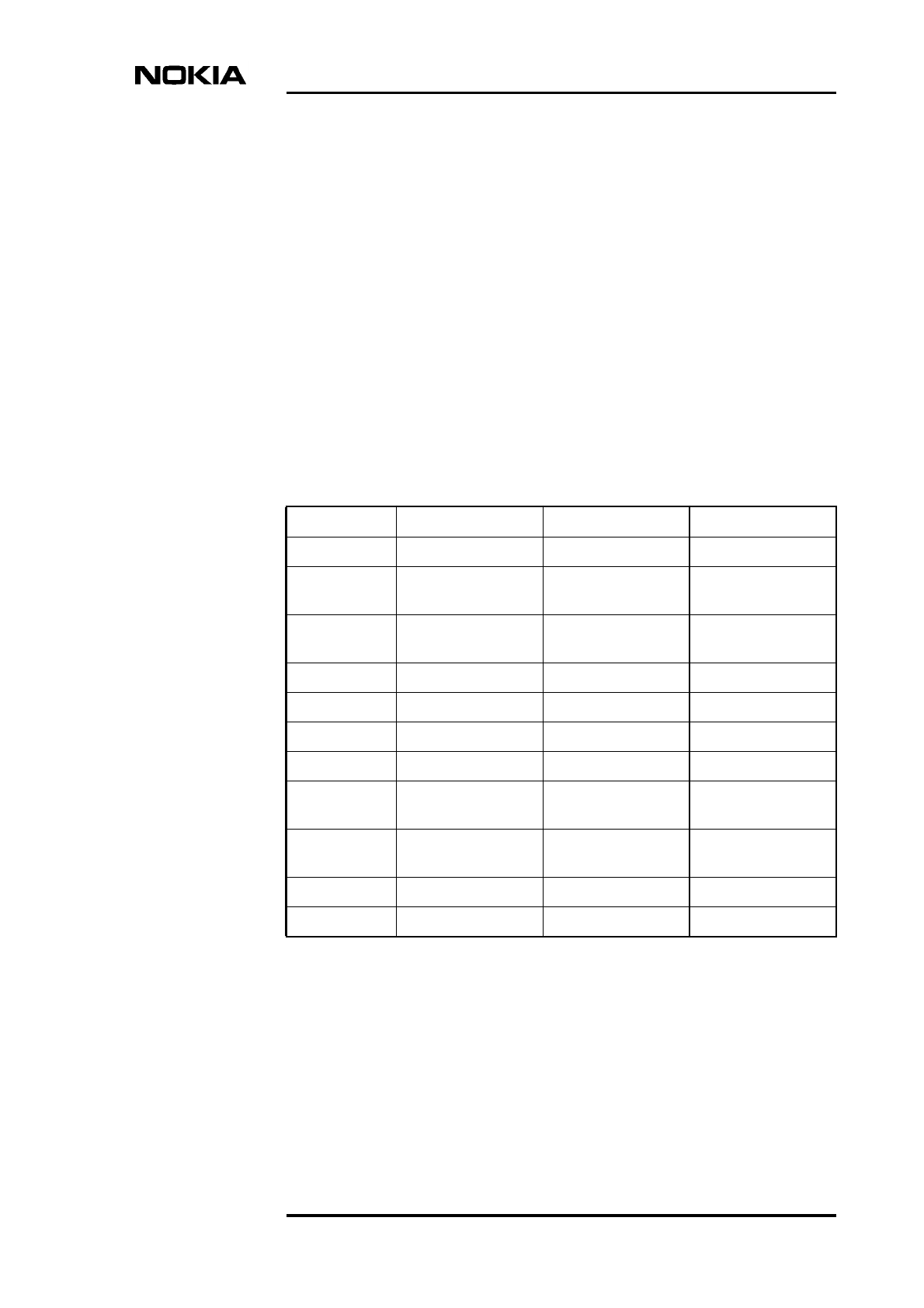
Unit alternatives and other delivery items
DN991444 © Nokia Corporation Draft 73 (98)
Issue 3-0 en Draft Nokia Proprietary and Confidential
7Unit alternatives and other delivery
items
This chapter details the unit alternatives for Nokia MetroSite EDGE Base
Stations.
Table 10. Transceiver unit alternatives
Input power Frequency band Unit type Notes
5 W GSM 900 HVTGA Standard filter
5 W GSM 900 HVTGH Customer specific
filter
5 W GSM 900 HVTGJ Customer specific
filter
5 W GSM 1800 HVTDA Standard filter
5 W GSM 1900 HVTPA Standard filter
5 W GSM/EDGE 800 WTFA Standard filter
5 W GSM/EDGE 900 WTGA Standard filter
5 W GSM/EDGE 900 WTGH Customer specific
filter
5 W GSM/EDGE 900 WTGJ Customer specific
filter
5 W GSM/EDGE 1800 WTDA Standard filter
5 W GSM/EDGE 1900 WTPA Standard filter
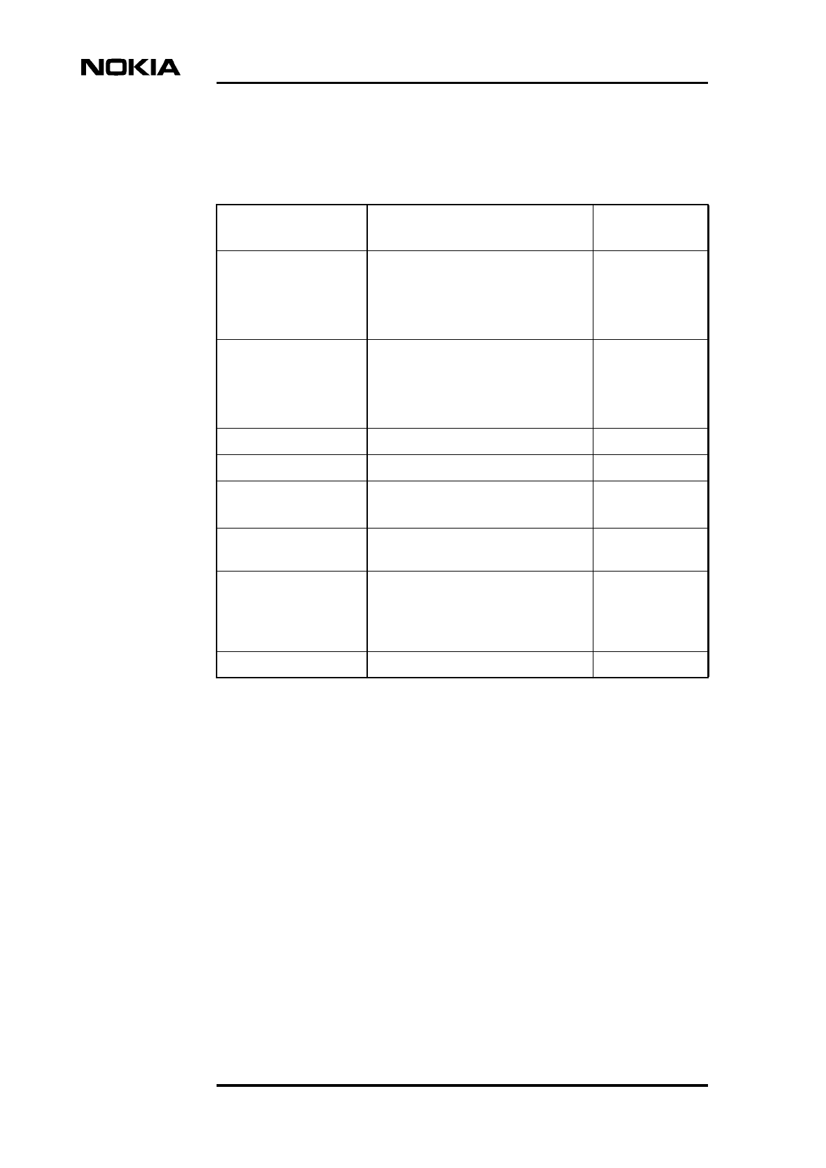
Product Description
74 (98) © Nokia Corporation Draft DN991444
Nokia Proprietary and Confidential Issue 3-0 en Draft
Prefabricated LMP, EAC, power (AC and DC), Flexbus, Extension and Q1 cables
for the Nokia MetroSite EDGE Base Station can also be ordered from Nokia.
Table 11. Nokia MetroSite EDGE Base Station unit alternatives and other
delivery items
Unit/Item Alternatives Nokia
abbreviations
Transmission unit FXC RRI
FC E1/T1
FXC E1 75 Ω
FXC E1/T1 120/100 Ω
VXRB
VXEA
VXTA
VXTB
Power supply unit AC 230 V
AC 110 V
DC -48 V
DC +24 V
HVSA
HVSB
HVSD
HVSC
Interface unit - VIFA
Fan unit - HVMF
Cover unit Standard
NEBS cover
HVCU
WCUA
Nokia MetroSite BTS
Manager
--
Customer documents Nokia MetroSite EDGE Base Station
Product Overview
Nokia MetroSite EDGE Base Station
User Manual
-
Options Pole mounting kit -
Technical specifications
DN991444 © Nokia Corporation Draft 75 (98)
Issue 3-0 en Draft Nokia Proprietary and Confidential
8Technical specifications
The purpose of this chapter is to provide all the necessary technical data for the
Nokia MetroSite EDGE Base Station.
Table 12. Common technical data
Property Value Note
Height 871 mm (34.3 in) 954 mm (37.56 in)
including the cables cover
Width 310 mm (12.20 in) -
Depth 215 mm (8.46 in) -
Weight Maximum 40 kg (88.18
lb) with four TRXs
Approximately 18 kg (39.68
lb) without TRXs. Heaviest
single part is 8 kg (17.66
lb).
Low temperature limit - 40°C (-40°F) -
High temperature limit + 50°C (122°F) -
Ingress protection class IP55
UL50-3R
Protection class of units
within cabinet
Acoustic noise 55 dBA typical
61 dBA maximum
(Sound power)
Nominal input voltage
(external supply voltage)
230 VAC
110 VAC
-48 VDC
+24 VDC
-
-
(-36 to -60 VDC)
(+20 to +28 VDC)
Permitted operating voltage
fluctuation
184 VAC - 276 VAC
85 VAC - 145 VAC
-28 VDC - -72 VDC
+20 VDC - +28 VDC
(44 Hz - 65 Hz)
(44 Hz - 65 Hz)
Product Description
76 (98) © Nokia Corporation Draft DN991444
Nokia Proprietary and Confidential Issue 3-0 en Draft
Typical power demand 300 W
340 W
5W GSM TRXs
5W GSM/EDGE TRXs
• Four TRXs
• FC E1/T1
• No heating
Maximum power demand 420 W
630 W
5W GSM TRXs
5W GSM/EDGE TRXs
• 1900 MHz TRXs
• Four TRXs
• FXC RRI
• 2 FlexiHoppers
• Worst case heating
scenario
Cooling fan capacity 120 m3/hr (4238 ft3/hr) -
Table 13. Specific technical data for the 5W GSM 900 TRX
Property Value Note
TX frequency range A: 925 - 960 MHz
H: 943 - 960 MHz
J: 935 - 960 MHz
Extended GSM
H and J are
customer specific
filters
RX frequency range A: 880 - 915 MHz
H: 897.5 - 915 MHz
J: 890.1 - 915 MHz
H and J with
improved isolation
between TX and
RX bands
Channel spacing 200 KHz -
Available radio channels 174 -
TX output power at antenna
connector, nominal
37 dBm ± 2dB at 20°C
(68°F), ± 2.5dB at
extreme
temperatures
Dynamic power range 30 dB (15 x 2 dB steps) -
Table 12. Common technical data (Continued)
Property Value Note
Technical specifications
DN991444 © Nokia Corporation Draft 77 (98)
Issue 3-0 en Draft Nokia Proprietary and Confidential
Static RX sensitivity -108.0 dBm
-106.0 dBm
Nominal
Minimum
RX diversity Yes With two or more
TRXs in one
sector
Isolation requirement for
antenna or external combiner
equipment
Minimum 25 dB -
Table 14. Specific technical data for the 5W GSM 1800 TRX
Property Value Note
TX frequency range 1805 - 1880 MHz -
RX frequency range 1710 - 1785 MHz -
Channel spacing 200 KHz -
Available radio channels 374 -
TX output power at antenna
connector, nominal
37 dBm ± 2 dB at 20°C
(68°F), ±2.5 dB at
extreme
temperatures
Dynamic power control 30 dB (15 x 2 dB steps) -
Static RX sensitivity -108.0 dBm
-106.0 dBm
Nominal
Minimum
RX diversity Yes With two or more
TRXs in one
sector
Isolation requirement for
antenna or external combiner
equipment
Minimum 25 dB -
Table 13. Specific technical data for the 5W GSM 900 TRX (Continued)
Property Value Note
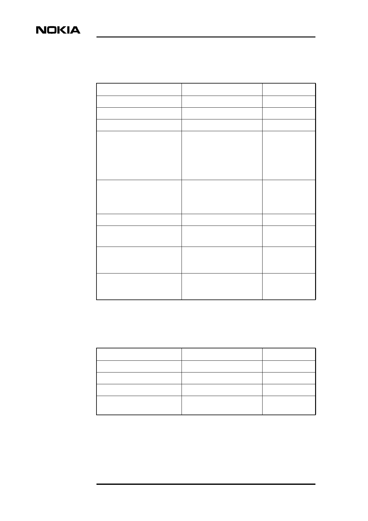
Product Description
78 (98) © Nokia Corporation Draft DN991444
Nokia Proprietary and Confidential Issue 3-0 en Draft
Table 15. Specific technical data for the 5W GSM 1900 TRX
Property Value Note
TX frequency range 1930 - 1990 MHz -
RX frequency range 1850 - 1910 MHz -
Channel spacing 200 KHz -
Available radio channels 293 (298) Five blocked
channels. More
options available
for certain
markets in the
future.
TX output power at antenna
connector, nominal
37 dBm ± 2 dB at 20°C
(68°F), ±2.5 dB at
extreme
temperatures
Dynamic power control 30 dB (15 x 2 dB steps) -
Static RX sensitivity -108.0 dBm
-106.0 dBm
Nominal
Minimum
RX diversity - With two or more
TRXs in one
sector
Isolation requirement for
antenna or external combiner
equipment
Minimum 25 dB -
Table 16. Specific technical data for the 5W GSM/EDGE 800 TRX
Property Value Note
TX frequency range A: 869 - 894 MHz -
RX frequency range 824 - 829 MHz -
Channel spacing 200 KHz -
Available radio channels 119 Four blocked
channels
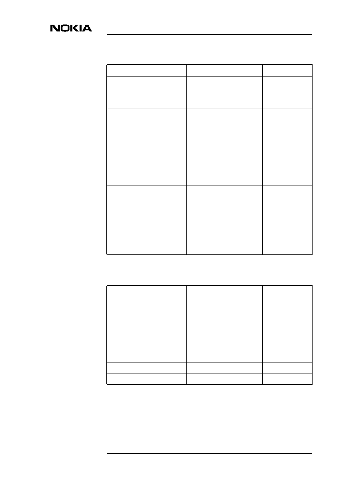
Technical specifications
DN991444 © Nokia Corporation Draft 79 (98)
Issue 3-0 en Draft Nokia Proprietary and Confidential
TX output power at antenna
connector, nominal
37 dBm (GMSK)
35 dBm (8-PSK)
± 2 dB at 20°C
(68°F), ±2.5 dB at
extreme
temperatures
Dynamic power range Static power level range
(BCCH):
• 18 dB (GMSK)
• 10 dB (8-PSK)
Total (static + dynamic) power
level range:
• 30 dB (GMSK)
• 16 dB (8-PSK)
Step size: 2 dB
-
Static RX sensitivity -108.0 dBm (GMSK)
-106.0 dBm (GMSK)
Nominal
Minimum
RX diversity Yes With two or more
TRXs in one
sector
Isolation requirement for
antenna or external combiner
equipment
Minimum 25 dB -
Table 17. Specific technical data for the 5W GSM/EDGE 900 TRX
Property Value Note
TX frequency range A: 925 - 960 MHz
H: 943 - 960 MHz
J: 935 - 960 MHz
Extended GSM
H and J are
customer specific
filters
RX frequency range A: 880 - 915 MHz
H: 898 - 915 MHz
J: 890 - 915 MHz
H and J with
improved isolation
between TX and
RX bands
Channel spacing 200 KHz -
Available radio channels 174 -
Table 16. Specific technical data for the 5W GSM/EDGE 800 TRX
Property Value Note
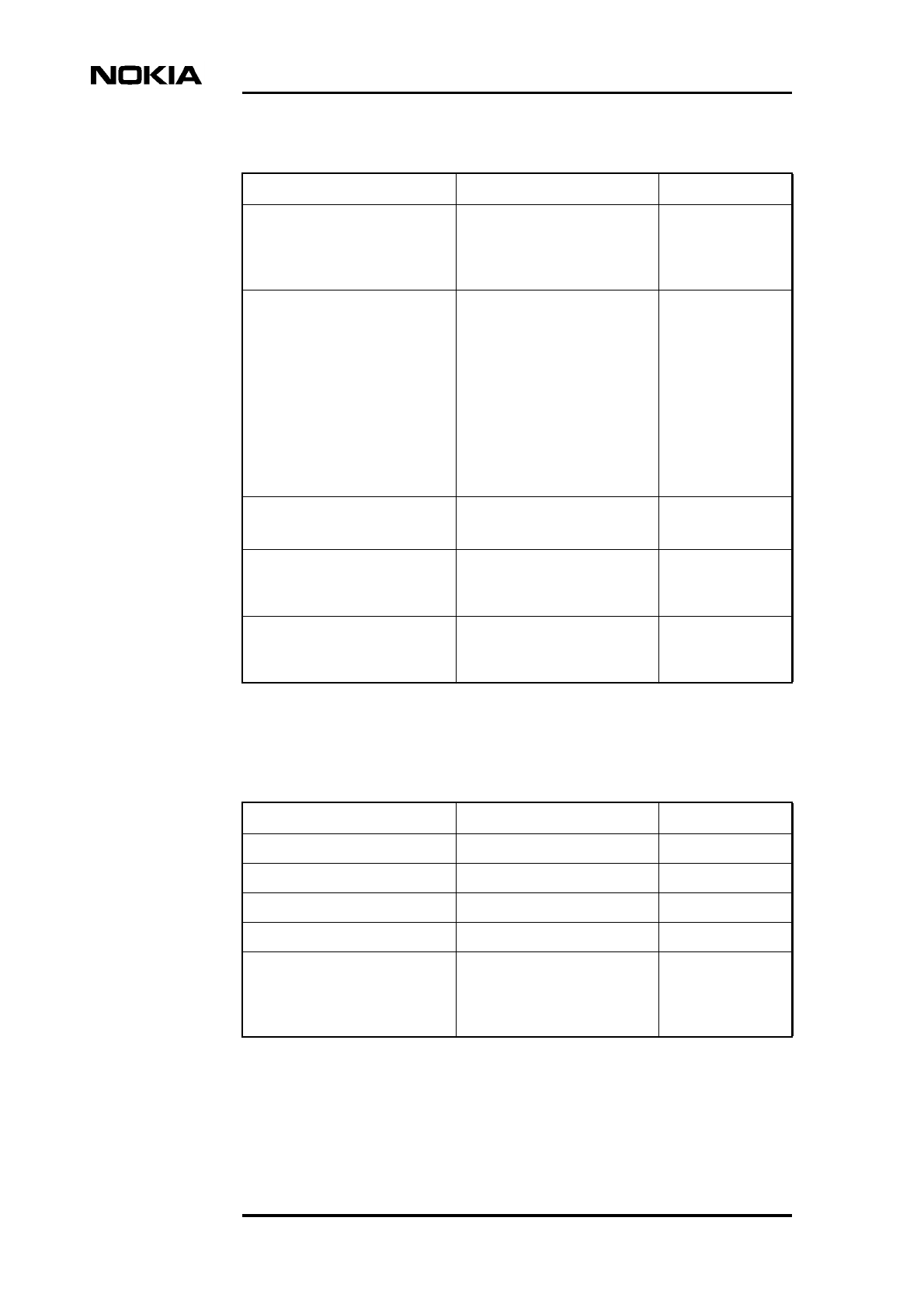
Product Description
80 (98) © Nokia Corporation Draft DN991444
Nokia Proprietary and Confidential Issue 3-0 en Draft
TX output power at antenna
connector, nominal
37 dBm (GMSK)
35 dBm (8-PSK)
± 2 dB at 20°C
(68°F), ±2.5 dB at
extreme
temperatures
Dynamic power range Static power level range
(BCCH):
• 18 dB (GMSK)
• 10 dB (8-PSK)
Total (static + dynamic) power
level range:
• 30 dB (GMSK)
• 16 dB (8-PSK)
Step size: 2 dB
-
Static RX sensitivity -108.0 dBm (GMSK)
-106.0 dBm (GMSK)
Nominal
Minimum
RX diversity Yes With two or more
TRXs in one
sector
Isolation requirement for
antenna or external combiner
equipment
Minimum 25 dB -
Table 18. Specific technical data for the 5W GSM/EDGE 1800 TRX
Property Value Note
TX frequency range A: 1805 - 1880 -
RX frequency range A: 1710 - 1785 MHz -
Channel spacing 200 KHz -
Available radio channels 374 -
TX output power at antenna
connector, nominal
37 dBm (GMSK)
35 dBm (8-PSK)
± 2 dB at 20°C
(68°F), ±2.5 dB at
extreme
temperatures
Table 17. Specific technical data for the 5W GSM/EDGE 900 TRX
Property Value Note
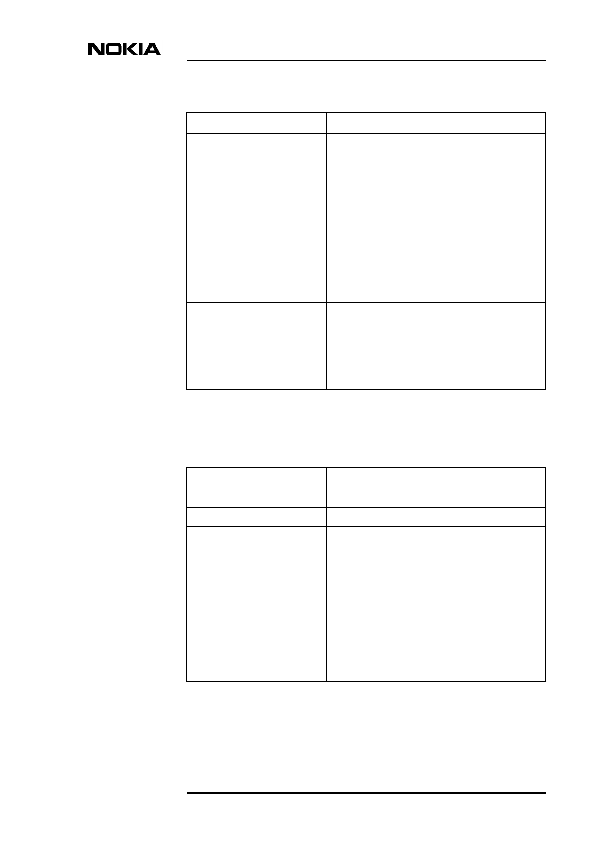
Technical specifications
DN991444 © Nokia Corporation Draft 81 (98)
Issue 3-0 en Draft Nokia Proprietary and Confidential
Dynamic power control Static power level range
(BCCH):
• 18 dB (GMSK)
• 10 dB (8-PSK)
Total (static + dynamic) power
level range:
• 30 dB (GMSK)
• 16 dB (8-PSK)
Step size: 2 dB
-
Static RX sensitivity -108.0 dBm (GMSK)
-106.0 dBm (GMSK)
Nominal
Minimum
RX diversity Yes With two or more
TRXs in one
sector
Isolation requirement for
antenna or external combiner
equipment
Minimum 25 dB -
Table 19. Specific technical data for the 5W GSM/EDGE 1900 TRX
Property Value Note
TX frequency range A: 1930 - 1990 MHz -
RX frequency range A: 1850 - 1910 MHz -
Channel spacing 200 KHz -
Available radio channels 293 (298) Five blocked
channels. More
options available
for certain
markets in the
future.
TX output power at antenna
connector, nominal
37 dBm (GMSK)
35 dBm (8-PSK)
± 2 dB at 20°C
(68°F), ±2.5 dB at
extreme
temperatures
Table 18. Specific technical data for the 5W GSM/EDGE 1800 TRX
Property Value Note
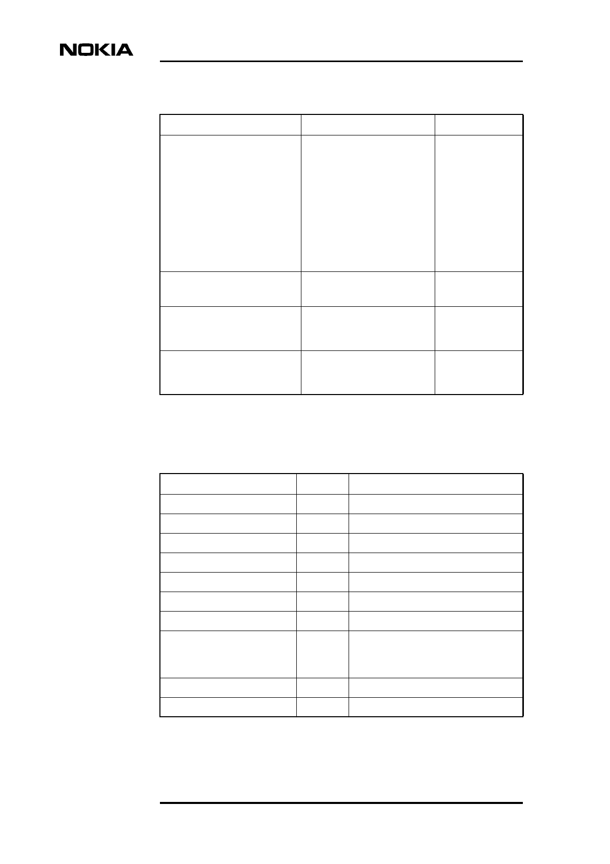
Product Description
82 (98) © Nokia Corporation Draft DN991444
Nokia Proprietary and Confidential Issue 3-0 en Draft
Dynamic power control Static power level range
(BCCH):
• 18 dB (GMSK)
• 10 dB (8-PSK)
Total (static + dynamic) power
level range:
• 30 dB (GMSK)
• 16 dB (8-PSK)
Step size: 2 dB
-
Static RX sensitivity -108.0 dBm (GMSK)
-106.0 dBm (GMSK)
Nominal
Minimum
RX diversity - With two or more
TRXs in one
sector
Isolation requirement for
antenna or external combiner
equipment
Minimum 25 dB -
Table 20. HW interfaces of Nokia MetroSite EDGE Base Station
Interface Number Connector type/note
Antenna connectors 1 to 4 N-type (female), one for each TRX
RX diversity connectors 2 to 8 SMA (female), two for each TRX
AC supply 230 V 1 IEC 320 (male)
AC supply 110 V 1 IEC 320 (male), with a notch
DC supply -48 V 1 Anderson Power Pole
DC supply -24 V 1 Anderson Power Pole
Grounding 1 Cable clamp
External alarms and controls 1 10 alarm inputs, 26-pin mini D-type
(female)
4 control outputs
Extension connectors 2 Out/In: 50-pin mini D-type (female)
13 MHz clock interface 1 MCX (female)
Table 19. Specific technical data for the 5W GSM/EDGE 1900 TRX
Property Value Note
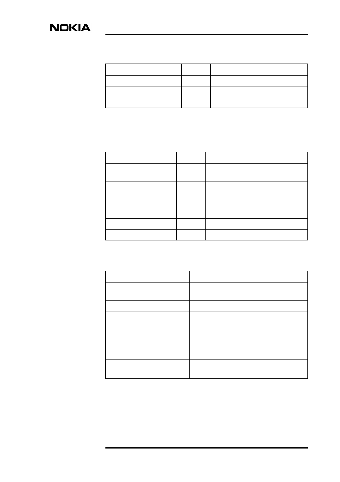
Technical specifications
DN991444 © Nokia Corporation Draft 83 (98)
Issue 3-0 en Draft Nokia Proprietary and Confidential
Frame clock 1 MCX (female)
Q1 interface 1 TQ
Local management port (LMP) 1 BQ, RS-232
Table 21. Transmission interfaces of Nokia MetroSite EDGE Base Station
Interface Number Connector type/note
FC RRI 1 TNC (50 Ω), Flexbus connection to
outdoor unit
FXC RRI 2 TNC (50 Ω), Flexbus connection to
outdoor unit
FC E1/T1 2
1
BT43 (75 Ω)
TQ (120/100 Ω)
FXC E1 (75 Ω) 8 BT43
FXC E1/T1 (120/100 Ω)4 TQ
Table 22. Flexbus cable characteristics
Property Value
Cable type Coaxial cable, double shielded or semi-rigid
(recommended types RG-223, RG-214)
Characteristic impedance 50 ± 2 Ω
DC resistance < 4.6 Ω (sum of inner and outer conductor)
Data attenuation < 9.0 dB at 19 MHz
Flexbus signals DC power supply
Bidirectional data (37 Mbit/s, NRZ code, 1.4 V
pulse amplitude)
Length Maximum 140 m for RG-223
Maximum 300 m for RG-214
Table 20. HW interfaces of Nokia MetroSite EDGE Base Station (Continued)
Interface Number Connector type/note
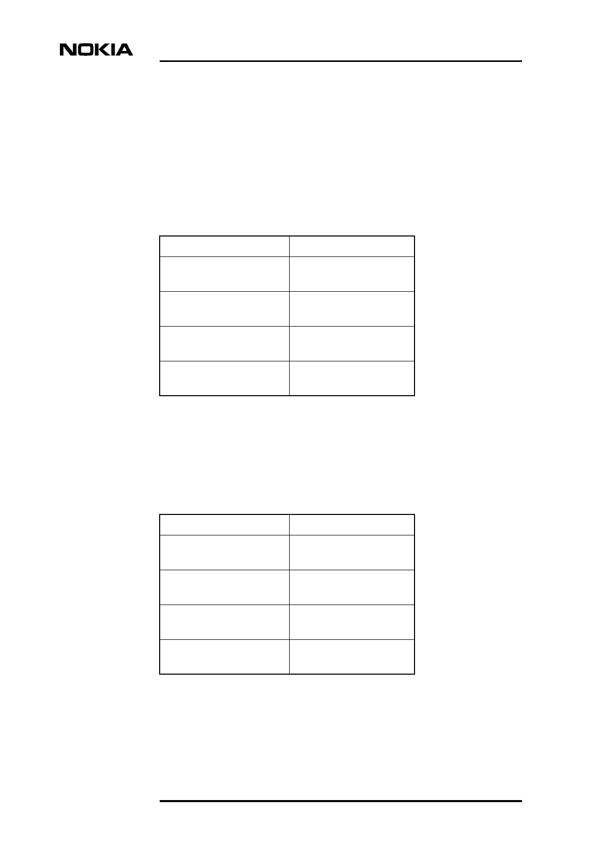
Product Description
84 (98) © Nokia Corporation Draft DN991444
Nokia Proprietary and Confidential Issue 3-0 en Draft
8.1 Dimensions and weights of plug-in units
This section presents the dimensions and weights of the plug-in units.
8.1.1 Transceiver unit
8.1.2 Interface unit
Table 23. Dimensions and weight of the TRX
Dimension Value
Height 314 mm
12.4 in
Width 61 mm
2.4 in
Depth 233 mm
9.2 in
Weight 4.5 kg
9.9 lb
Table 24. Dimensions and weight of the interface unit
Dimension Value
Height 58 mm
2.3 in
Width 152 mm
6.0 in
Depth 200 mm
7.9 in
Weight 1 kg
2.2 lb
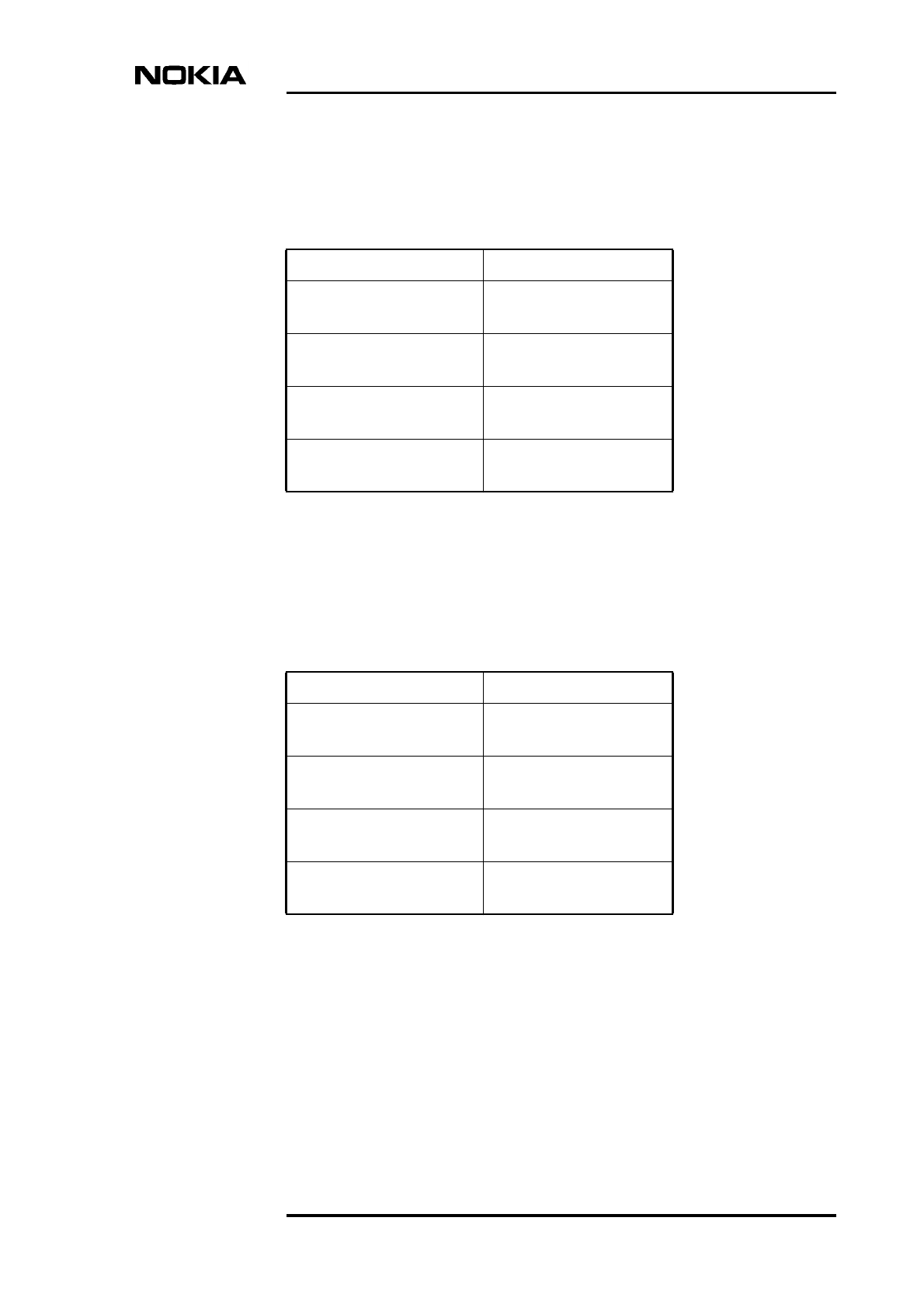
Technical specifications
DN991444 © Nokia Corporation Draft 85 (98)
Issue 3-0 en Draft Nokia Proprietary and Confidential
8.1.3 Transmission unit
8.1.4 Power supply unit
8.2 System requirements for Nokia MetroSite BTS
Manager
System requirements for Nokia MetroSite BTS Manager are detailed in Table 27.
Table 25. Dimensions and weight of the transmission unit
Dimension Value
Height 254 mm
10 in
Width 28 mm
1.10 in
Depth 164 mm
6.5 in
Weight 1.35 kg
3 lb
Table 26. Dimensions and weight of the power supply unit
Dimension Value
Height 245 mm
9.7 in
Width 60 mm
2.4 in
Depth 268 mm
10.6 in
Weight < 4 kg (depending on type)
< 8.8 lb
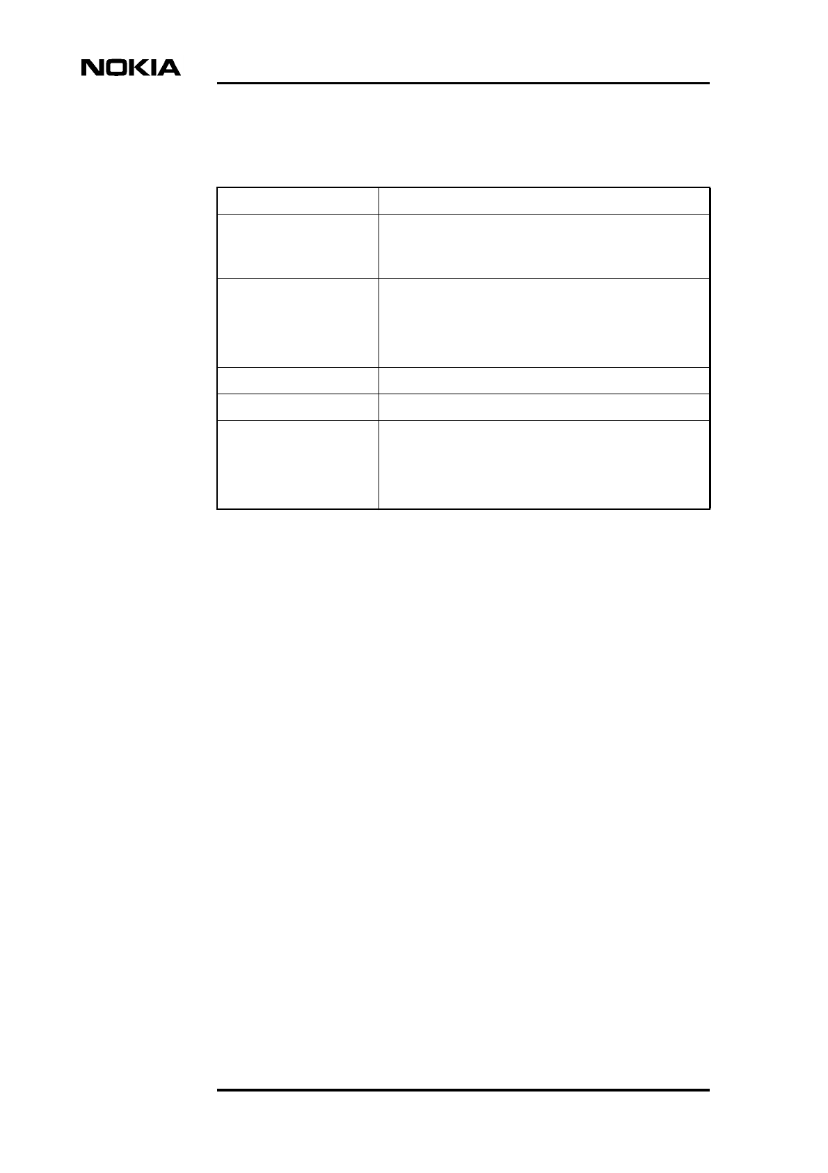
Product Description
86 (98) © Nokia Corporation Draft DN991444
Nokia Proprietary and Confidential Issue 3-0 en Draft
8.3 Basic telecommunication features
The Nokia MetroSite EDGE Base Station supports the following basic
telecommunication features:
• DRX, discontinuous reception
• DTX, discontinuous transmission
• Handover and power control algorithms
• Stand-alone Dedicated Control Handover (SDCH)
• Interference band selection based on MS power
• Logical channel configurations (based on GSM/DCS recommendation
05.02.)
• Full Rate Speech
• Ciphering (support for A5/0,1,2)
• FACCH emergency call set-up
Table 27. System requirements for Nokia MetroSite BTS Manager
Computer Intel Pentium based IBM-compatible PC
Operating system Microsoft Windows NT 4.0 (with service pack 4)
Microsoft Windows 95 (or Microsoft Windows 98) with
service pack 1
System memory
(minimum)
Microsoft Windows NT 4.0:
• 32 MB RAM
Microsoft Windows 95 or 98:
• 16 MB RAM
Monitor SVGA, min 800x600 resolution
Minimum disk space 40 MB
Accessories CD-ROM drive
Windows compatible mouse or pointing device
Windows compatible printer (optional)
Cable (PC - BTS)
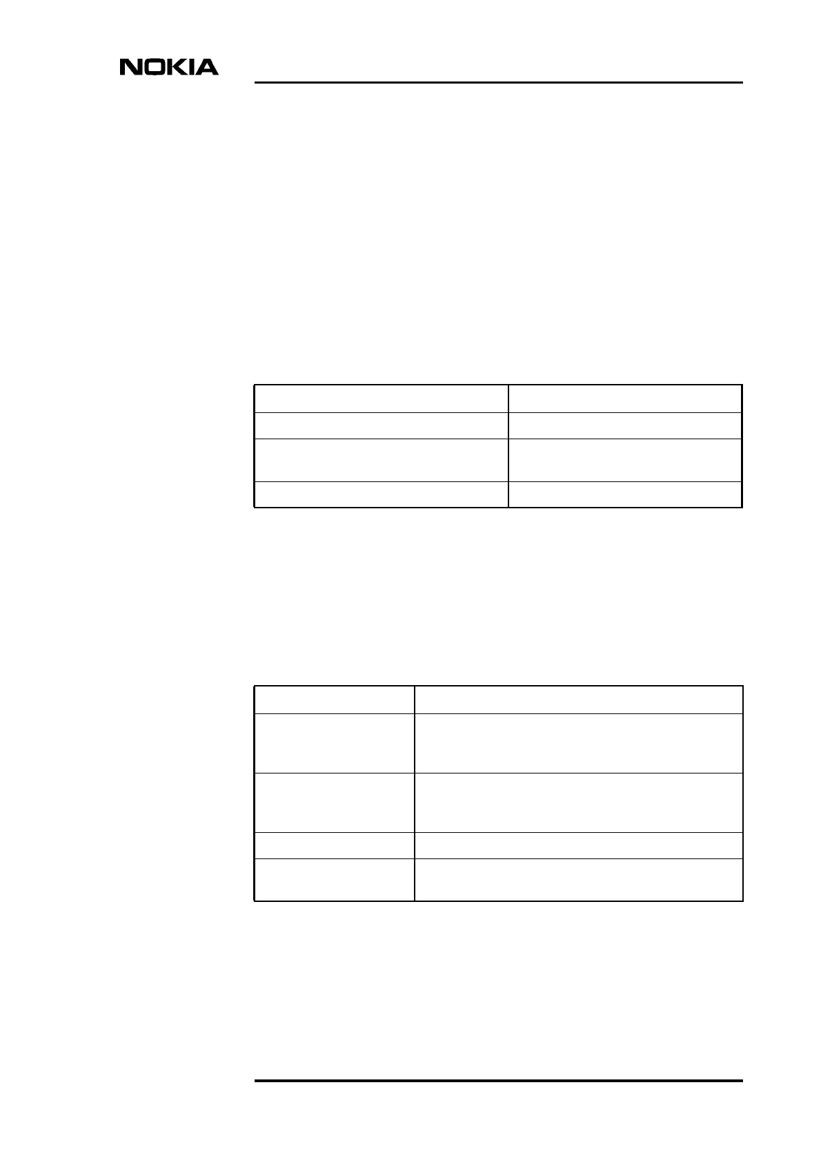
Technical specifications
DN991444 © Nokia Corporation Draft 87 (98)
Issue 3-0 en Draft Nokia Proprietary and Confidential
8.4 International recommendations
This section lists the recommendations referred to in the designing of the Nokia
MetroSite EDGE Base Station.
8.4.1 Common standards
Table 28 lists the common standards referred to in the designing of the Nokia
MetroSite EDGE Base Station.
8.4.2 Electrical standards
The tables of this section list the electrical standards referred to in the designing
of the Nokia MetroSite EDGE Base Station.
Table 28. Common standards
Standard Description
ETSI GSM 05.05/11.20/11.21/11.22/11.23 Standard for base station equipment
T1.713-2000 Personal Communications Services,
PCS 1900 Specifications
TIA/EIA PN-3777 EMC specific
Table 29. Input voltage standards
Standard Description
ETS 300 132-1:1996 Equipment Engineering Power Supply Interface at the
input to Telecommunications Equipment Interface
Operated by Alternating Current (AC)
ETS 300 132-2:1996 Power Supply Interface at the input to
telecommunications equipment interface operated by
direct current (DC)
GSM 11.20 Standard for base station equipment
ETS 300 253, 1995 Earthing and bonding of telecommunication equipment in
telecommunication centres
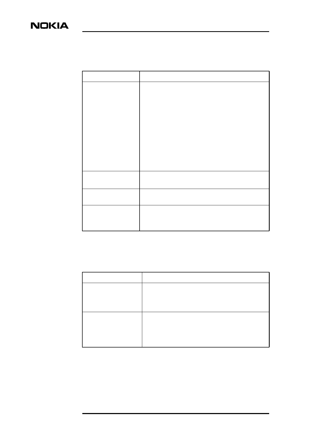
Product Description
88 (98) © Nokia Corporation Draft DN991444
Nokia Proprietary and Confidential Issue 3-0 en Draft
Table 30. Electrical safety standards
Standard Description
EN 60950: 1992
A1: 1992
A2: 1993
A3: 1995
A4: 1996
IEC 950: 1991
A1: 1992
A2: 1993
A3: 1995
A4: 1996
Safety of Information Technology Equipment, including
Electrical Business Equipment + Amendments A1, A2, A3
and A4
UL1950: 1995, 3rd
edition
Standard for Safety of Information Technology Equipment,
including Electrical Business Equipment
FCC Part 68 Rules for Registration of Telephone Equipment PART 68:
1995
EN 60215:1988
IEC 215: 1987
BS 3192
Safety requirements for radio transmitting equipment
Table 31. Product specific EMC standards
Standard Description
ETS 300 342 2, 1994 Radio Equipment and Systems (RES); Electro-Magnetic
Compatibility (EMC) for European digital cellular
telecommunications system (GSM 900 and DCS 1800
MHz) Part 2: Base station and ancillary equipment
d-ETS 300 342-3:1997 Radio Equipment and Systems (RES); Electro-Magnetic
Compatibility (EMC) for European digital cellular
telecommunications system Part 3: Base station and
ancillary equipment and repeaters meeting, Phase 2,
GSM requirements

Technical specifications
DN991444 © Nokia Corporation Draft 89 (98)
Issue 3-0 en Draft Nokia Proprietary and Confidential
ETSI GSM 11.20
ETSI GSM 11.21
Standard for base station equipment
Standard for base station equipment
ANSI T1.713-2000 Personal Communications Services; PCS 1900
Specifications
TIA/EIA PN-3777 EMC specific
Table 32. Basic EMC standards based on d-ETS 300 342-3:1997
Standard Description
ETSI GSM 11.21 Standard for base station equipment
EN 55022, class B, 1994
(IEC/CISPR 22, 1993)
EN 55022/A1:1995
Limits and methods of measurement of radio
interference characteristics of information technology
equipment
EN 61000-4-2: 1995
IEC 1000-4-2: 1995
Electromagnetic Compatibility (EMC) Part 4: Testing and
measurement techniques Section 2: Electrostatic
discharge immunity test: Basic EMC publication
EN 61000-4-3: 1995
IEC 1000-4-3: 1995
Electromagnetic Compatibility (EMC) Part 4: Testing and
measurement techniques Section 3: Radiated, radio-
frequency, electromagnetic field immunity test
EN 61000-4-4: 1995
IEC-1000-4-4: 1995
Electromagnetic Compatibility (EMC) Part 4: Testing and
measurement techniques Section 4: Electrical fast
transient/burst immunity test: Basic EMC publication
EN 61000-4-5: 1995
IEC-1000-4-5: 1995
Electromagnetic Compatibility (EMC) Part 4: Testing and
measurement techniques Section 5: Surge immunity
test
EN 61000-4-6: 1996
IEC 1000-4-6: 1996
Electromagnetic Compatibility (EMC) Part 4: Testing and
measurement techniques Section 6: Immunity to
conducted disturbances, induced by radio-frequency
fields
IEC 1000-4-11: 1994
EN 61000-4-11: 1994
Electromagnetic Compatibility (EMC) Part 4: Testing and
measurement techniques Section 11: Voltage dips, short
interruptions and voltage variations immunity tests
Table 31. Product specific EMC standards (Continued)
Standard Description

Product Description
90 (98) © Nokia Corporation Draft DN991444
Nokia Proprietary and Confidential Issue 3-0 en Draft
8.4.3 Environment
The environmental standards referred to in the designing of Nokia MetroSite
EDGE Base Station are described in this section.
Table 33. Additional EMC standards
Standard Description
FCC Part 15
FCC Part 24
FCC Rules for Radio Equipment Devices
Personal Communication Services
IEC 1000-3-2,
EN 60555-2
BS 5406 Part 2
Electromagnetic Compatibility (EMC)
Part 3: Limits - Section 2: Limits for
harmonic current emission (equipment
input current ≤16 A per phase)
IEC 1000-3-3: 1994
EN 61000-3-3: 1995
EN 60555-3: BS 5406
Electromagnetic Compatibility (EMC)
Part 3: Limits - Section 3: Limitation of
voltage fluctuation and flicker in low-
voltage supply systems for equipment
with rated current ≤16 A
IEC 1000-4-8: 1993 Electromagnetic Compatibility (EMC)
Part 4: Testing and measurement
techniques Section 8: Power frequency
magnetic field immunity test: Basic EMC
publication
IEC 1000-4-9: 1993 Electromagnetic Compatibility (EMC)
Part 4: Testing and measurement
techniques Section 9: Pulse magnetic
field immunity test: Basic EMC
publication

Technical specifications
DN991444 © Nokia Corporation Draft 91 (98)
Issue 3-0 en Draft Nokia Proprietary and Confidential
8.4.4 Mechanical standards
The mechanical standards referred to in the designing of the Nokia MetroSite
EDGE Base Station are described in this section.
Table 34. Environmental standards
Standard Description
ETS 300 019-1-1:1992
ETS 300 019-2-1:1994
Equipment Engineering (EE); Environmental conditions
and environmental tests for telecommunications
equipment Part 1-1: Classification of environmental
conditions: Storage
Equipment Engineering (EE); Environmental conditions
and environmental tests for telecommunications
equipment Part 2-1: Specification of environmental
tests: Storage
ETS 300 019-1-2:1992
ETS 300 019-2-2:1994
Equipment Engineering (EE); Environmental conditions
and environmental tests for telecommunications
equipment Part 1-2: Classification of environmental
conditions: Transportation
Equipment Engineering (EE); Environmental conditions
and environmental tests for telecommunications
equipment Part 2-2: Specification of environmental
tests: Transportation
ETS 300 019-1-4:1992
ETS 300 019-2-4:1994
Equipment Engineering (EE); Environmental conditions
and environmental tests for telecommunications
equipment Part 1-4: Classification of environmental
conditions: Stationary use at non-weather protected
locations
Equipment Engineering (EE); Environmental conditions
and environmental tests for telecommunications
equipment Part 2-2: Specification of environmental
tests: Stationary use at non-weather protected locations
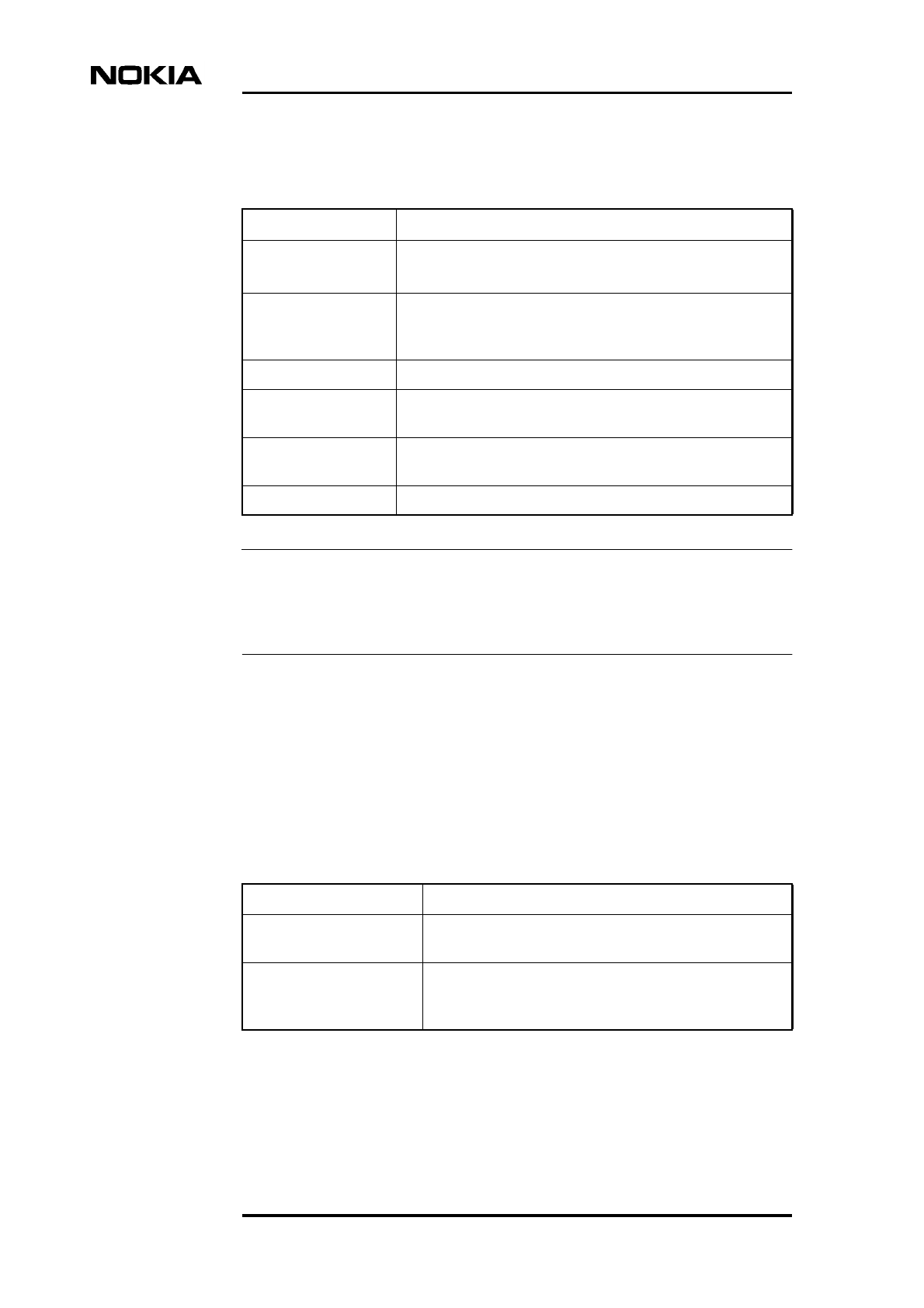
Product Description
92 (98) © Nokia Corporation Draft DN991444
Nokia Proprietary and Confidential Issue 3-0 en Draft
Note
The Nokia MetroSite EDGE BTS is designed to meet GR-63-CORE (NEBS) and
GR-487-CORE only when fitted with the WCUA type cover (high impact
polycarbonate).
8.4.5 Base station interface equipment - related recommendations and
standards
The standards and recommendations related to base station interface equipment
are described in this section.
Table 35. Mechanical standards
Standard Description
EN 60659
BS 5490
Degree of Protection Provided by Enclosures (IP Code)
ISO 3744, 1988 Acoustics determination of sound power levels of noise
sources: Engineering methods for special reverberation test
rooms
ETS 300 753 Acoustic noise emitted by telecommunications equipment
IEC 68-2-57: 1989 Environmental Testing Part 2: Test Methods Ff: Vibration
Time-history Method.
GR-63-CORE:1995 Network Equipment-Building System (NEBS): Physical
Protection
GR-487-CORE Corrosion Resistance - Temperature Cycling/High Humidity
Table 36. Flexbus interface
Standard Description
ITU-T G.704 (10/94) Synchronous frame structures used at primary and
secondary hierarchical levels
ITU-T G.706 (1991) Frame alignment and cyclic redundancy check (CGC)
procedures relating to basic frame structures defined in
Recommendation G.704

Technical specifications
DN991444 © Nokia Corporation Draft 93 (98)
Issue 3-0 en Draft Nokia Proprietary and Confidential
ITU-T G.823 (03/93) The control of jitter and wander within digital networks
which are based on the 2048 Kbit/s hierarchy
ITU-T G.826 (08/96) Error performance parameters and objectives for
international, constant bit rate digital paths at or above
primary rate
ITU-T G.921 Digital sections based on the 2048 Kbit/s hierarchy
Table 37. 2048 Kbit/s E1 interface
Standard Description
CCITT (Blue Book):
• G.703
• G.704
• G.706
• G.711
• G.732
• G.736
• G.826
• G.823
• I.460
• Digital Interface Characteristics
• Functional Interface Characteristics
• CRC Multiframe Structure
• PCM Coding Law
• Primary PCM Multiplexer
• Synchronous 2 Mbit/s Digital Multiplexer
• Jitter and Wander
• Performance Parameters
• Multiplexing, Rate Adaption
GSM:
• 03.50
• 08.51
• 08.54
• 08.52
• Transmission Planning Aspects
• BSC-BTS Interface, General Aspects
• BSC-BTS Interface Principles
• BSC BTS Interface Layer 1, Structure of Physical
Circuits
Table 36. Flexbus interface (Continued)
Standard Description
Product Description
94 (98) © Nokia Corporation Draft DN991444
Nokia Proprietary and Confidential Issue 3-0 en Draft
Table 38. 1544 Kbit/s T1 interface
Standard Description
ANSI T1.403 and T1.102
ANSI T1.403
Digital Interface Characteristics
Functional Interface Characteristics
PCM Coding Law
Primary PCM Multiplexer
Synchronous 2 Mbit/s Digital Multiplexer
Performance Parameters
AT&T TR 62411 Jitter and Wander Multiplexing, Rate Adaptation

DN991444 ©Nokia Corporation Draft 95 (98)
Issue 3-0 en Draft Nokia Proprietary and Confidential
Index
Numerics
8-PSK (8 Phase Shift Keying) 57
A
Abis interface 15
Air interface 15
alarm diagnostics 27
antenna 22
applications 31
autodetection 25
B
baseband module 54
battery backup 28
BBU 28
BCF (base control functions) 47
broadcast control channel (BCCH) 21
broadcast control channel (BCCH) TRX 32
BSC (base station controller) 15
BTS 13
building capacity 19
C
cabinet 48
C-bus 47
cell, network management system. 20
chain connection 36
chaining 20
channel DSP (CH) block 56
coverage area, types of. 32
D
D1-bus 46
D2-bus 46
digital part 58
dimensions
interface unit 84
plug -in units 84
power supply unit 85
transceiver unit 84
transmission unit 85
dual band operation 19
duplex filter part 59
E
EAC (external alarms and controls) 62
enhanced full rate speech coding 23
Enhanced General Packet Radio Service (EGPRS)
24
extension interface 62
F
fan unit 70
F-bus 47
F-bus interface 56
FC E1 T1 36,64
FC RRI 36
features, BTS. 19
Flexbus 63
Flexbus, characteristics. 83
Flexbus, interface. 93
frequency hopping 22
frequency re -use 21
FXC E1 36,65
FXC E1 T1 36,66
FXC RRI 36,63
G
General Packet Radio Service (GPRS) 24
GMSK (Gaussian Minimum Shift Keying) 57
GSM data services 23
H
half rate speech coding 23
HSCSD (high speed circuit switched data 23
I
installation possibilities 24
interface unit
dimensions and weight 84
technical information 59
internal function, BTS. 45
international recommendations 87
L
LMB (Local Management Bus) 46
LMP (Local Management Port) 60
LNA (Low Noise Amplifier) 58
loop connection 36

Product Description
96 (98) © Nokia Corporation Draft DN991444
Nokia Proprietary and Confidential Issue 3-0 en Draft
M
master TRX 27
microcells, building. 31
mobile station (MS) 15
MSC (mobile switching centre) 15
N
network quality 21
Nokia MetroSite BTS Manager 39,40
Nokia MetroSite Capacity Solution 17
Nokia MetroSite EDGE Base Station 16
Nokia MetroSite EDGE Base Station software 39
Nokia SiteWizard 41
non -transparent data 23
O
OSS (operational support system) 15
output voltages 68
P
plug -in units
locations 51
plug -in units 51
power distribution 47
power supply unit
connector types 69
dimensions and weight 85
unit alternatives 68
power supply unit 68
Q
Q1 connector 61
Q1-bus 47
Q1int-bus 47
R
radio link transmission, unit alternatives. 63
receiver (RX) part 58
receiver diversity 21
RF loop part 58
RF module 56
S
safety requirementsSee standards 75
SCF (Site Configuration File) 26
sectoring 19
shield units 24
signalling
between BTS and external equipment 46
internal 46
signalling 43
slave TRX 27
software 39
standards
BTS interfaces 92
common 87
electrical 87
electrical safety 87
EMC 88
environmental 90
input voltage 87
mechanical 91
star connection 36
system requirements 85
T
technical data
common 75
GSM 1800 TRX 77
GSM 1900 TRX 77
GSM 900 TRX 76
GSM/EDGE 1800 TRX 80
GSM/EDGE 1900 TRX 81
GSM/EDGE 800 TRX 78
hardware interfaces 82
transmission interfaces 83
technical specifications 75
telecommunication features, advanced. 23
telecommunication features, basic. 86
temperature control 28
TQ connector 64
traffic channel TRX 32
transceiver unit (TRX)
dimensions and weight 84
external interfaces 59
transceiver unit (TRX) 52
transmission 36
transmission node 15
transmission unit
dimensions and weight 85
transmission unit 63
transmitter (TX) part 57
transparent data 23
TRX mechanics 59
TRX test 27

DN991444 ©Nokia Corporation Draft 97 (98)
Issue 3-0 en Draft Nokia Proprietary and Confidential
U
unit alternatives 73
unit controller (UC) block 56
uplink diversity 21
W
weight
BTS 75
interface unit 84
plug -in units 84
power supply unit 85
transceiver unit 84
transmission unit 85
wireline transmission, unit alternatives. 64

Product Description
98 (98) © Nokia Corporation Draft DN991444
Nokia Proprietary and Confidential Issue 3-0 en Draft