Powerwave Technologies 5JS0056 Multi Carrier RF Power Amplifier User Manual 273677
Powerwave Technologies Inc Multi Carrier RF Power Amplifier 273677
Contents
Manual 2

G3S-800-140-031 Installation & Service Manual
Copyright Powerwave Technologies, Inc., September 2001. All rights reserved
044-05095 Rev. A 2-1 September 2001
Section 2 Installation
2-1 Introduction
This section contains installation recommendations, unpacking, inspection, and installation in-
structions for the Multicarrier Cellular Amplifier. Carefully read all material in this section prior to
equipment unpacking or installation. Also read and review the operating procedures in Section 3
prior to installing the equipment. It is important that the licensee perform these tasks correctly
and in good faith. If applicable, carefully review the Federal Communications Commission (FCC)
rules as they apply to your installation. DON'T TAKE CHANCES WITH YOUR LICENSE.
2-2 Electrical Service Recommendations
Powerwave Technologies recommends that proper AC line conditioning and surge suppression
be provided on the primary AC input to the +27 Vdc power source. All electrical service should
be installed in accordance with the National Electrical Code, any applicable state or local codes,
and good engineering practice. Special consideration should be given to lightning protection of
all systems in view of the vulnerability of most transmitter sites to lightning. Lightning arrestors
are recommended in the service entrance. Straight, short ground runs are recommended. The
electrical service must be well grounded.
Each amplifier system should have its own circuit breaker, so a failure in one does not shut off
the whole installation. Circuit breakers should be capable of handling the anticipated inrush cur-
rent (normally 25% over equipment maximum current draw), in a load center with a master
switch. A 70-amp circuit breaker installed in the power distribution unit is recommended for each
amplifier. Either 2 or 4 AWG DC wire should be installed for each amplifier based on the cable
design and length.
Table 2-1 Averaged Current
Amplifier
Power
No. Of
Amplifiers
3 Sector
Averaged Current
2 Sector
Averaged Current
1 Sector
Averaged Current
140 12 588
140 9 441 504
140 6 294 336 378
140 1 49 56 63
2-3 Air Conditioning
Each G3S-800-140-031 amplifier generates 5971 BTUs of heat at full power. A fully populated
MCR30829-1-3 subrack operating at full power will generate 17,913 BTUs of heat. A full three-
sector site employing three fully populated MCR30829-1-3 subracks will generate 53,739 BTUs
of heat at full power (360W per subrack). A five-ton air conditioner is needed to cool this Power-
wave equipment. A full three-sector site probably needs at least a five-ton air conditioner to cool
all of the site's equipment, based on heat load averaging as described in table 2-2. Since all the
amplifiers are not running at full capacity at the same time in normal operation, table 2-2 de-
scribes the heat load for a 3 sector (70%), 2 sector (80%) and omni (90%) site. Perform a site
survey to determine actual air conditioning needs.

G3S-800-140-031 Installation & Service Manual
Copyright Powerwave Technologies, Inc., September 2001. All rights reserved
044-05095 Rev. A 2-2 September 2001
Table 2-2 Averaged Heat Loading
Amplifier
Power
No. Of
Amplifiers
3 Sector
Averaged BTU's
2 Sector
Averaged BTU's
1 Sector
Averaged BTU's
140 12 50,156.4
140 9 37,617.3 42,991.2
140 6 25,078.2 28,660.8 32,243.4
140 1 4,179.7 4,776.8 5,373.9
2-4 Unpacking And Inspection
This equipment has been operated, tested and calibrated at the factory. Only in the event of se-
vere shocks or other mistreatment should any substantial readjustment be required. Carefully
open the container(s) and remove the amplifier module(s). Retain all packing material that can
be reassembled in the event that the unit must be returned to the factory.
CAUTION
Exercise care in handling equipment during inspection to prevent damage caused by
rough or careless handling.
Visually inspect the amplifier module for damage that may have occurred during shipment.
Check for evidence of water damage, bent or warped chassis, loose screws or nuts, or extrane-
ous packing material in the connector or fans. Inspect the rear panel connector for bent connec-
tor pins. If the equipment is damaged, a claim should be filed with the carrier once the extent of
any damage is assessed. We cannot stress too strongly the importance of IMMEDIATE careful
inspection of the equipment and the subsequent IMMEDIATE filing of the necessary claims
against the carrier if necessary. If possible, inspect the equipment in the presence of the delivery
person. If the equipment is damaged, the carrier is your first area of recourse. If the equipment
is damaged and must be returned to the factory, write or phone for a return authorization. Pow-
erwave may not accept returns without a return authorization. Claims for loss or damage may
not be withheld from any payment to Powerwave, nor may any payment due be withheld pending
the outcome thereof. WE CANNOT GUARANTEE THE FREIGHT CARRIER'S PERFORM-
ANCE.
2-5 Installation Instructions (refer to figures 1-1 and 2-1)
The G3S-800-140-031 amplifier module is designed for installation in a subrack for connection of
DC power, RF, and monitor cables.
To install the amplifier proceed as follows:
1. Install the subrack in an equipment rack and secure in place, based on the installation in-
structions from the appropriate manual for the subrack being installed.
2. Connect the subrack RF output to a high quality transmit filter. Powerwave recommends that
a 500W average power / 10KW instantaneous peak power rated filter be used in most appli-
cations.
3. Connect the combined transceiver output(s) to the RF Input port of subrack.
4. Connect the alarm cable(s) to the alarm port of subrack.
G3S-800-140-031 Installation & Service Manual
Copyright Powerwave Technologies, Inc., September 2001. All rights reserved
044-05095 Rev. A 2-3 September 2001
WARNING
Verify that all circuit breaker switches on the power distribution panel are in the OFF
position. Turn off external primary DC power before connecting DC power cables.
5. Connect positive primary power and negative primary power to the subrack. Tighten the
subrack power connections.
6. Verify that the plug-in amplifier’s front panel On/Off switch is in the Off position.
7. Inspect the 21-pin D-Sub male combo connector on the rear of each amplifier before install-
ing the amplifier in the amplifier subrack. Verify that all pins are straight, no pins are re-
cessed, that the alignment shield is not bent, and no packing material is embedded in the
connector.
CAUTION
Forcing the amplifier into the subrack at too fast a rate may cause the pins on the 21-
pin D-sub connector of the amplifier to become recessed or broken.
8. Install the plug-in amplifier module(s) in the subrack. Tighten left and right thumbscrews un-
til finger tight. Tighten the thumbscrews with a slotted screw driver about 1/8 of a turn past
finger tight.
9. Check your work before applying DC voltage to the system. Make certain all connections
are tight and correct.
10. Turn the power distribution circuit breakers back on.
11. Measure primary DC input voltage. DC input voltage should be +27 Vdc ±1.0 Vdc. If the
DC input voltage is above or below the limits, call and consult Powerwave before you turn on
your amplifier system.
12. Refer to section 3 for initial turn-on and checkout procedures.
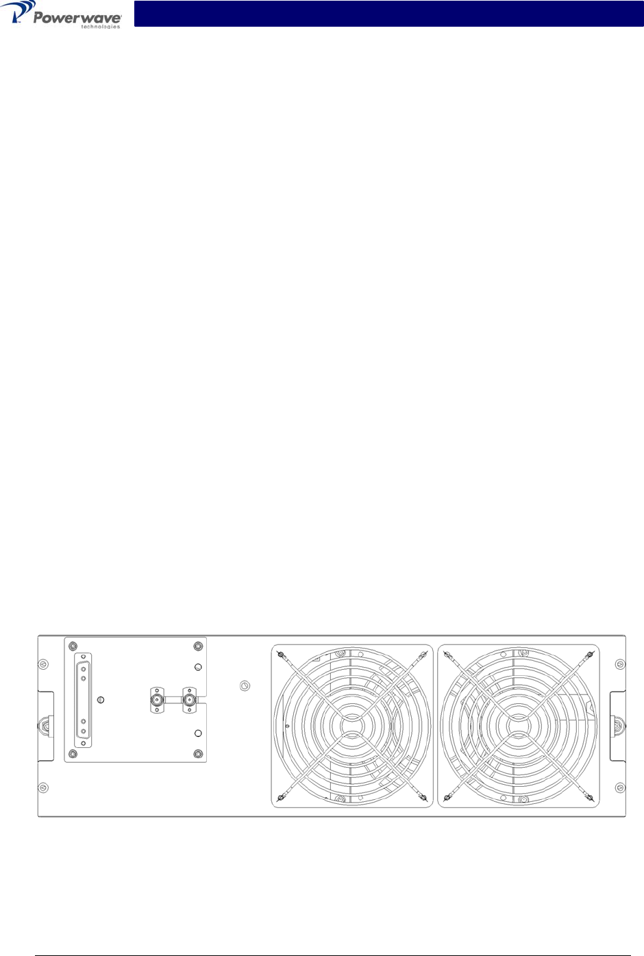
2-6 Amplifier Module Connectors
The amplifier has three connectors on the right rear of the module. The larger is a 21-pin male
D-Sub combo, which provides the status, alarm, control, and power connections. The smaller
BMA coaxial female connectors provide the RF connections. Refer to figure 2-1.
Figure 2-1 G3S-800-140-031 Amplifier, Rear View
G3S-800-140-031 Installation & Service Manual
Copyright Powerwave Technologies, Inc., September 2001. All rights reserved
044-05095 Rev. A 2-4 September 2001
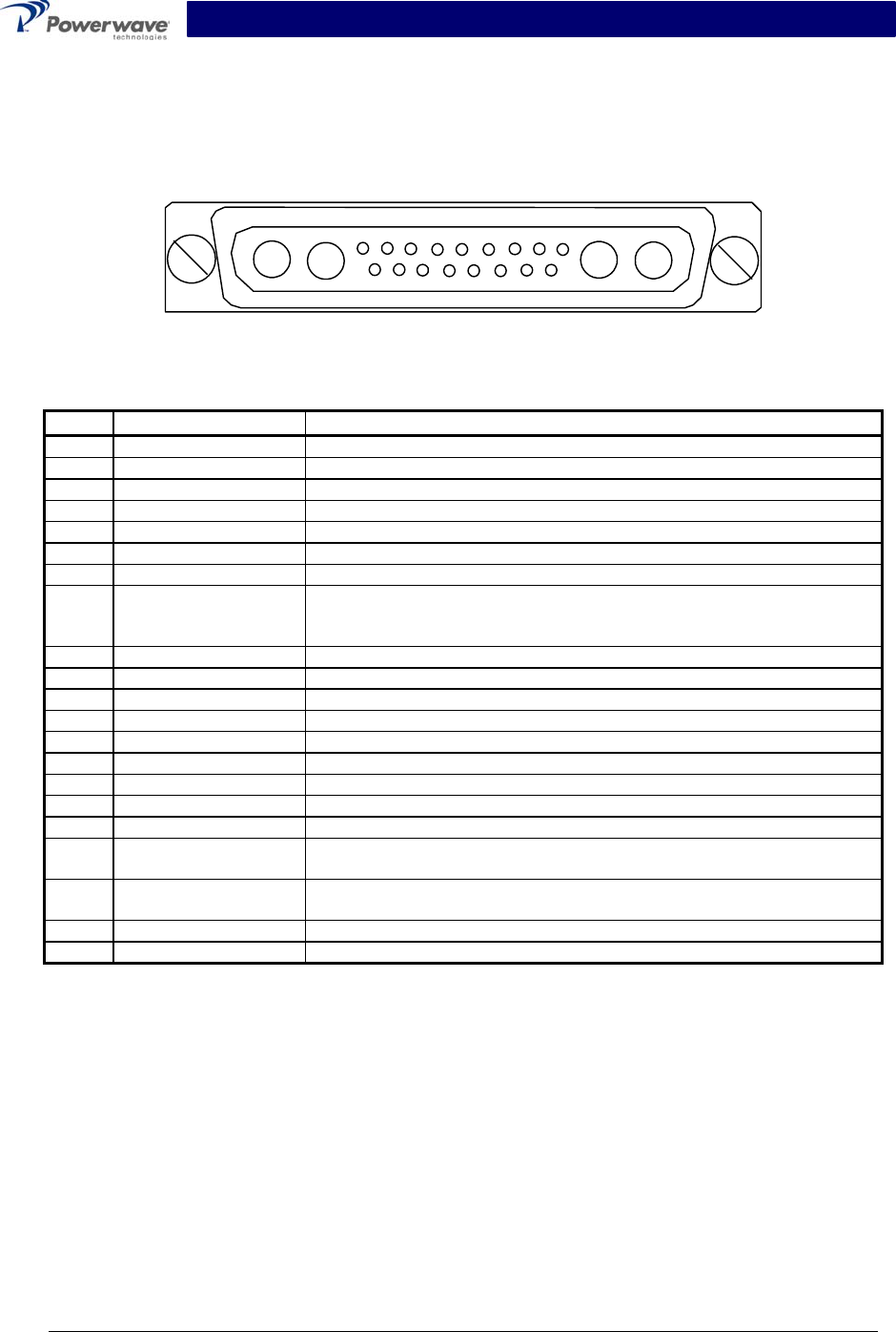
2-6.1 Amplifier Module Status, Alarm, Control, And Power Connector
The amplifier has a separate remote alarm and control connector, which may be used by the host
system to monitor and control the individual amplifier modules. The status, alarm, control, and
power connections on the amplifier connector are made through a 21-pin male D-Sub combo
connector (figure 2-2) and are listed and described in table 2-3.
A1 A2 A3 A4
1 2 3 4 5 6 7 8 9
10 11 12 13 14 15 16 17
Figure 2-2 DC and Logic Connector (on Rear of G3S-800-140-031 Amplifier Module)
Table 2-3 Amplifier Module DC and Logic Connector Definition
Pin Function Description
A1 Power Input +27 Vdc (Power Contact)
A2 Power Input +27 Vdc (Power Contact)
A3 Ground Ground (Power Contact)
A4 Ground Ground (Power Contact)
1 RS485 +TxD Serial Communication Data Out
2 RS485 +RxD Serial Communication Data In
3 Service Loop TTL input to Amp. Gnd. for special test mode (Note 1)
4 MCPA Disabled
(Summary Fault)
TTL signal normally low indicates MCPA enabled. A high level indicates
that the MCPA has been disabled. Over Power, Over Voltage takes
one second to activate the signal.
5 Mod Addr 0 TTL input to Amp. Gnd. supplied by shelf to identify slot.
6 Mod Addr 1 TTL input to Amp. Gnd. supplied by shelf to identify slot.
7 TP1 TTL output. Future test point.
8 Manual Download GND to download manually
9 DC on stat TTL output. High indicates Amp is powered on.
10 RS485 –TxD Serial Communication Data Out
11 RS485 –RxD Serial Communication Data In
12 SCL7 No connection
13 SDA7 No connection
14 FP Disable Output Output, GND if the front panel switch is in the OFF position; +5 volts in-
dicates the front panel switch is in the ON position.
15 FP RST Output, GND if the front panel switch is in the RESET position; +5 volts
otherwise.
16 GND Ground
17 Module Detect Ground potential. Informs the subrack that an MCPA is plugged in.
Note 1: Service loop grounded allows the MCPA to be enabled or disabled by the front panel
switch when not mounted in the shelf.
G3S-800-140-031 Installation & Service Manual
Copyright Powerwave Technologies, Inc., September 2001. All rights reserved
044-05095 Rev. A 2-5 September 2001
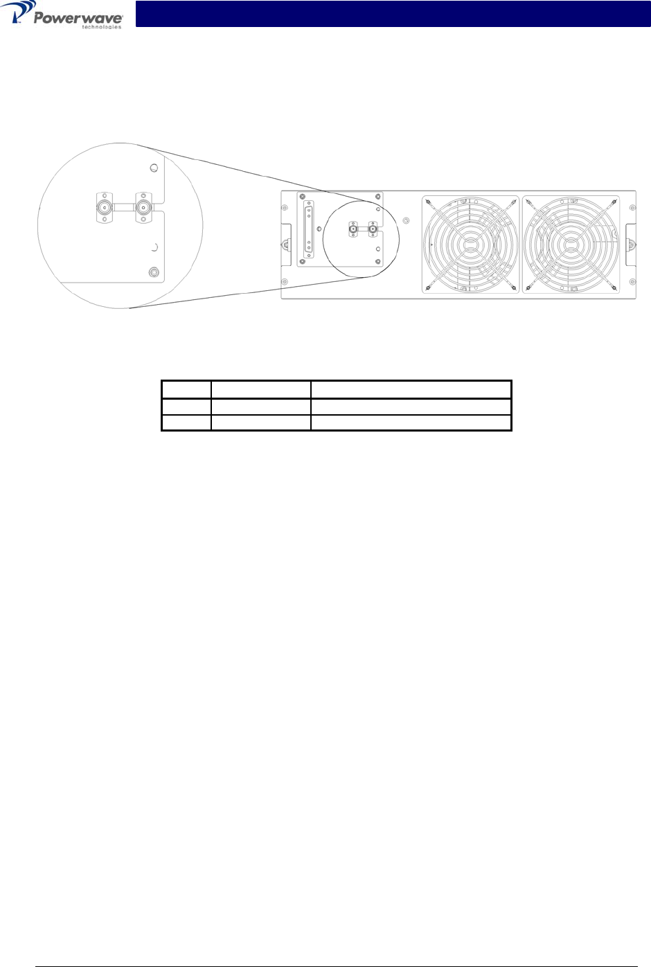
2-6.2 Amplifier Module RF Connector
The amplifier has separate RF connectors, which are used for the RF signal input and output.
The RF connections on the amplifier connector are made through two BMA female coaxial con-
nectors (figure 2-3) and are listed and described in table 2-4.
Figure 2-3 Amplifier RF Connector
Table 2-4 Amplifier RF Connector Definition
Pin Function Description
A1 RF Input BMA Coaxial Female, Radiall
A2 RF Output BMA Coaxial Female, Radiall
A
1 A2