Powerwave Technologies 5JS0056 Multi Carrier RF Power Amplifier User Manual 273676
Powerwave Technologies Inc Multi Carrier RF Power Amplifier 273676
Contents
Manual 1

G3S-800-140-031 Installation & Service Manual
Copyright Powerwave Technologies, Inc., September 2001. All rights reserved
All specifications are subject to change without notice. Contact the factory for complete performance data.
044-05095 Rev. A 1-1 September 2001
Section 1 General Description
1-1 Introduction
This manual contains information and procedures for installation, operation, and maintenance of
Powerwave’s G3S-800-140-031 multicarrier RF power amplifier. The manual is organized into
six sections as follows:
Section 1. General Description
Section 2. Installation
Section 3. Operating Instructions
Section 4. Principles of Operation
Section 5. Maintenance
Section 6. Troubleshooting
1-2 General Description
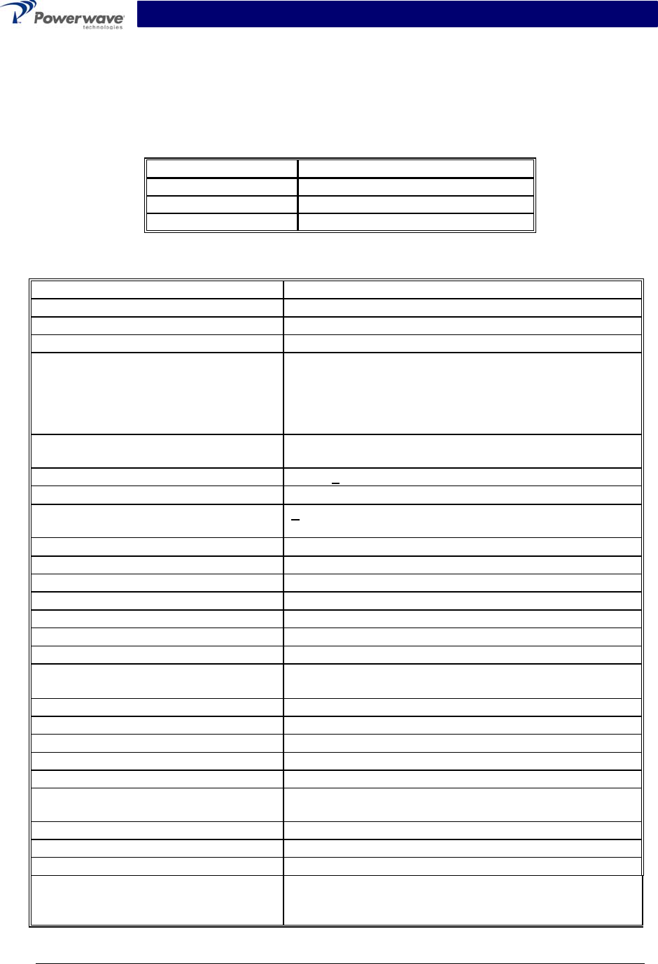
The G3S-800-140-031 (see figure 1-1) is a linear, feed-forward power amplifier that operates in
the frequency band from 851 MHz to 869 MHz. The amplifier can simultaneously transmit multi-
ple frequencies, with better than -60 dBc third order intermodulation distortion (IMD). It is de-
signed for use in an amplifier system that is modular in design, and is ideally suited for use in
base stations. The plug-in Model G3S-800-140-031 amplifier modules can each provide 140
watts of power and function completely independently of each other. The amplifier modules are
designed for parallel operation to produce high peak power output and backup redundancy for
remote applications. All solid-state, the system is designed to provide trouble-free operation with
minimum maintenance. The system's modular construction and unique and highly effective
LED-based operational status and fault indicators help minimize downtime. The turn-on and turn-
off sequences of voltages are fully automatic, as is overload protection and recycling. Inadver-
tent operator damage from front panel manipulation is virtually impossible.
The amplifier module has a status connector that allows the host system to monitor the amplifier
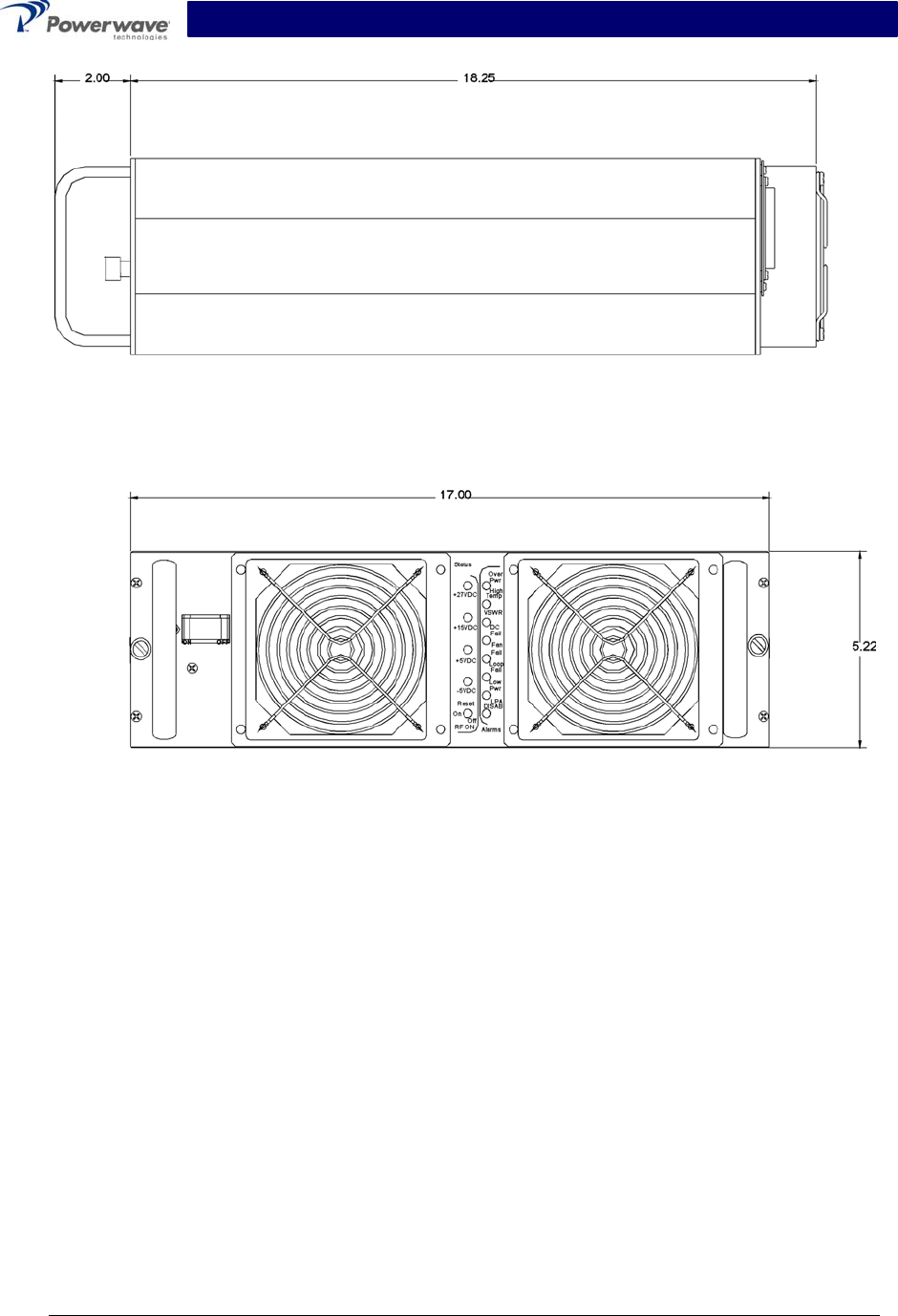
module performance. The front panel of each amplifier module has unit level status/fault indica-
tors and an RF on/off/reset switch. Primary power for the amplifier is +27 Vdc. Cooling for each
plug-in amplifier module is provided by four fans, two mounted on the front and two on the rear of
the module. The fans draw outside air through the front of the module and exhaust hot air out
through the rear of the module.
1-3 Functional And Physical Specifications
Functional and physical specifications for the amplifier are listed in table 1-2.
1-4 Equipment Changes
Powerwave Technologies, Inc. reserves the right to make minor changes to the equipment, in-
cluding but not necessarily limited to component substitution and circuitry changes. Changes that
impact this manual may subsequently be incorporated in a later revision of this manual.
G3S-800-140-031 Installation & Service Manual
Copyright Powerwave Technologies, Inc., September 2001. All rights reserved
All specifications are subject to change without notice. Contact the factory for complete performance data.
044-05095 Rev. A 1-2 September 2001
1-5 Ordering Information
Table 1-1 following gives the part numbers and descriptions to be used when ordering either an
entire amplifier or replacement fans.
Table 1-1 Major Amplifier Components
Model Number Description
G3S-800-140-031 140 W 851-869 MHz MCPA Module
800-01075-003 Front fan assembly
800-00972-002 Rear fan assembly.
Table 1-2 G3S-800-140 Multicarrier Cellular Amplifier Functional Specifications
Frequency Range 851-869 MHz (18 MHz Bandwidth)
Instantaneous Bandwidth 18 MHz
Total Maximum Input Power -6.54 dBm
Total Output Power 140 W (51.46 dBm) typical (1 Module)
IMD and In-band Spurious, mean
measurement, 30 kHz bandwidth@
+26 to +28Vdc, 25°C
-60dBc or -16 dBm max @ up to 16 equal power CW
tones with a combined maximum power of P0 with a
max single carrier power of P0/16 with maximum crest
factor of 7.5dB up to the maximum rated RF output
power.
Out of Band Spurious & Noise,
measured in 30 KHz BW
-60 dBc max @ +26 to +28 Vdc
RF Gain 58 dB +0.5 dB
Gain Flatness: ±0.5 dB @ 27 Vdc ±1 Vdc
Gain Variation w/ Voltage and
Frequency
+ 0.5 dB; 26 to 28 Vdc
Gain Variation Over Temperature: ±0.5 dB
Noise Figure 25 dB max
Output Protection: Mismatch Protected
Input Port Return Loss: 16 dB min
Harmonics: Better than -50 dBc
Out of Band Spurious: Better than -60 dBc
Duty Cycle: Continuous
DC Input Power: +27 Vdc ±1 Vdc, 70 amps max
Operational +21 Vdc to 30 Vdc
DC Circuit Breaker Rating 100 Amps
Operating Temperature: 0º C to +50º C
Storage Temperature: -40º C to +85º C
Operating Humidity: 0 % to 80 % Relative Humidity (noncondensing)
Storage Humidity: 0 % to 100 % Relative Humidity (noncondensing)
DC Input, Summary Alarm, and RF
Input / Output Connectors:
21-Pin D-Subminiature Combo Connector plus single-
pin D-Sub connector for additional DC capability.
Heat Generation 5510 BTUS (1 Amplifier)
Weight 50 lbs.
Dimensions: 5.20” High, 17.00” Wide, 20.00” Deep
Electrical Service Recommendations
Circuit Breakers
Capable of handling anticipated inrush current (nor-
mally 25% over equipment maximum current draw), in
a load center with a master switch.
G3S-800-140-031 Installation & Service Manual
Copyright Powerwave Technologies, Inc., September 2001. All rights reserved
All specifications are subject to change without notice. Contact the factory for complete performance data.
044-05095 Rev. A 1-3 September 2001
Figure 1-1 G3S-800-140-031