Powerwave Technologies 5JS0056 Multi Carrier RF Power Amplifier User Manual 273680
Powerwave Technologies Inc Multi Carrier RF Power Amplifier 273680
Contents
Manual 5

G3S-800-140-031 Installation & Service Manual
Copyright Powerwave Technologies, Inc., September 2001. All rights reserved
044-05095 Rev. A 5-1 September 2001
Section 5 Maintenance
5-1 Introduction
This section contains periodic maintenance and performance test procedures for the Multicarrier
Cellular Amplifier. It also contains a list of test equipment required to perform the identified tasks.
NOTE
Check your sales order and equipment warranty before attempting to service or repair
the unit. Do not break the seals on equipment under warranty or the warranty will be
null and void. Do not return equipment for warranty or repair service until proper
shipping instructions are received from the factory.
5-2 Periodic Maintenance
Periodic maintenance requirements are listed in table 5-1. Table 5-1 also lists the intervals at
which the tasks should be performed.
WARNING
Wear proper eye protection to avoid eye injury when using compressed air.
Table 5-1 Periodic Maintenance
Task Interval Action
Cleaning
Air Vents 30 Days Inspect and clean per paragraph 5-4
Inspection
Cables and Connec-
tors
12 Months Inspect signal and power cables for
frayed insulation. Check RF connectors
to be sure that they are tight.
Performance Tests 12 Months Perform annual test per paragraph 5-5.
5-3 Test Equipment Required For Test
Test equipment required to test the amplifier system is listed in table 5-2. Equivalent test equip-
ment may be substituted for any item, keeping in mind that a thermistor type power meter is re-
quired.
NOTE
All RF test equipment must be calibrated to 0.05 dB resolution. Any deviation from
the nominal attenuation must be accounted for and factored into all output readings.

G3S-800-140-031 Installation & Service Manual
Copyright Powerwave Technologies, Inc., September 2001. All rights reserved
044-05095 Rev. A 5-2 September 2001
Table 5-2 Test Equipment Required
Nomenclature Manufacturer Model
Signal Generator RDL IMD-801D-03A
30 dB Attenuator, 500 Watt Weinschel Corp. 53-30-34
20 dB Attenuator, 20 Watt
(2 each)
Tenuline
Spectrum Analyzer H.P. 8560E
Coax Directional Coupler H.P. 778D
Power Meter/Sensor H.P. 437B/8481A
Network Analyzer H.P. 8753C
Current Probe
5-4 Cleaning Air Inlets/Outlets
The air inlets and outlets should be cleaned every 30 days. If the equipment is operated in a se-
vere dust environment, they should be cleaned more often as necessary. Turn off DC power
source before removing fans. If dust and dirt are allowed to accumulate, the cooling efficiency
may be diminished. Using either compressed air or a brush with soft bristles, loosen and remove
accumulated dust and dirt from the air inlet panels.
5-5 Performance Test
Performance testing should be conducted every 12 months to ensure that the amplifier system
meets the operational specifications listed in table 5-3. Also verify system performance after any
amplifier module is replaced in the field. The test equipment required to perform the testing is
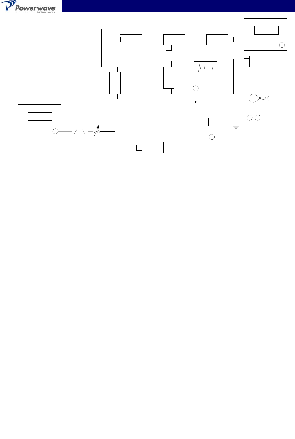
listed in table 5-2, and the test setup is shown in figure 5-1.
NOTE
The frequencies used in this test are typical for an amplifier with a 18 MHz band
from 851 MHz to 869 MHz. Select evenly spaced F1, F2, F3, and F4 frequencies
that cover the instantaneous bandwidth of your system.
5-5.1 Amplifier System Performance Test
This test is applicable to the G3S-800-140-031 amplifier modules. To perform the test, proceed
as follows:
1. Connect test equipment to the amplifier as shown in figure 5-1.
NOTE
Do not apply any RF signals at this time.
Turn on signal generator and set frequency F1 to 854 MHz, F2 to 857 MHz, F3 to 863 MHz,
and F4 to 866 MHz. Adjust each signal generator output so that the sum power output from
all four signal generators equals -6 dBm at the input.
G3S-800-140-031 Installation & Service Manual
Copyright Powerwave Technologies, Inc., September 2001. All rights reserved
044-05095 Rev. A 5-3 September 2001
Unit Under Test
G3S-800-140-031
Plug-in
A
mplifier
Module
+27 Vdc
Gnd RF In
RF
Out
20 dB
Directionl Coupler
30 dB
A
ttenuator
500 W
20 dB
A
ttenuator
20 W Power Meter
Sensor Head
8482A
20
dB
A
tt
en
ua
tor
20
W
Dir
ect
ion
l
Co
upl
er
Power Meter
Sensor Head
8482A
Network Analyzer
8753C
Signal
Generator
Filter /
Isotlator
10 dB
Variable
A
ttenuator
Spectrum Analyzer
8651E
Figure 5-1 Amplifier System Test Setup Diagram
5-5.1.1 Amplifier IMD Test And Current Test
2. Adjust attenuator for an input signal at -10 dBm. Turn on the amplifier by setting RF ON
switch of amplifier. Adjust variable attenuator to set amplifier power output on power meter
to 140 watts. Measure IMD on spectrum analyzer. IMD should be -60 dBc max. Record
test data in table 5-3. Set RF ON switch to OFF.
3. With the amplifier module set at 140 watts power output, use the current probe (magnetic
field type) and measure the dc current flow from the +27 Vdc power source. Current should
be 70 amps maximum. Record test data in table 5-3.
5-5.1.2 Gain Test
4. Disconnect spectrum analyzer from test setup, and connect the network analyzer.
5. Set network analyzer as follows:
¾ Power output to -10 dBm.
¾ Frequency start to 869 MHz.
¾ Frequency stop to 894 MHz.
¾ Normalize the network analyzer for gain and return loss.
6. Check the gain across the band from 869 MHz to 894 MHz. Gain should be between 58 dB.
Record test data in table 5-3.
5-5.1.3 Harmonics Test
7. With the power set at 140 watts power output, use the spectrum analyzer and check the fre-
quency band from 851 MHz to 869 MHz for harmonics. Harmonics should be 5 dBm maxi-
mum. Record test data in table 5-3.

G3S-800-140-031 Installation & Service Manual
Copyright Powerwave Technologies, Inc., September 2001. All rights reserved
044-05095 Rev. A 5-4 September 2001
5-5.1.4 Spurious Test
8. With the power amplifier set at 140 watts power output, use the spectrum analyzer and
check the frequency band from 851 MHz to 869 MHz for spurious signals. Spurious signals
should be -60 dBc maximum. Record test data in table 5-3.
5-5.1.5 Input Return Loss Test
9. Reset and turn on amplifier module. Read and record the S11 return loss measurement on
network analyzer. Input return loss should be –16 dB maximum. Record test data in table
5-3.
G3S-800-140-031 Installation & Service Manual
Copyright Powerwave Technologies, Inc., September 2001. All rights reserved
044-05095 Rev. A 5-5 September 2001
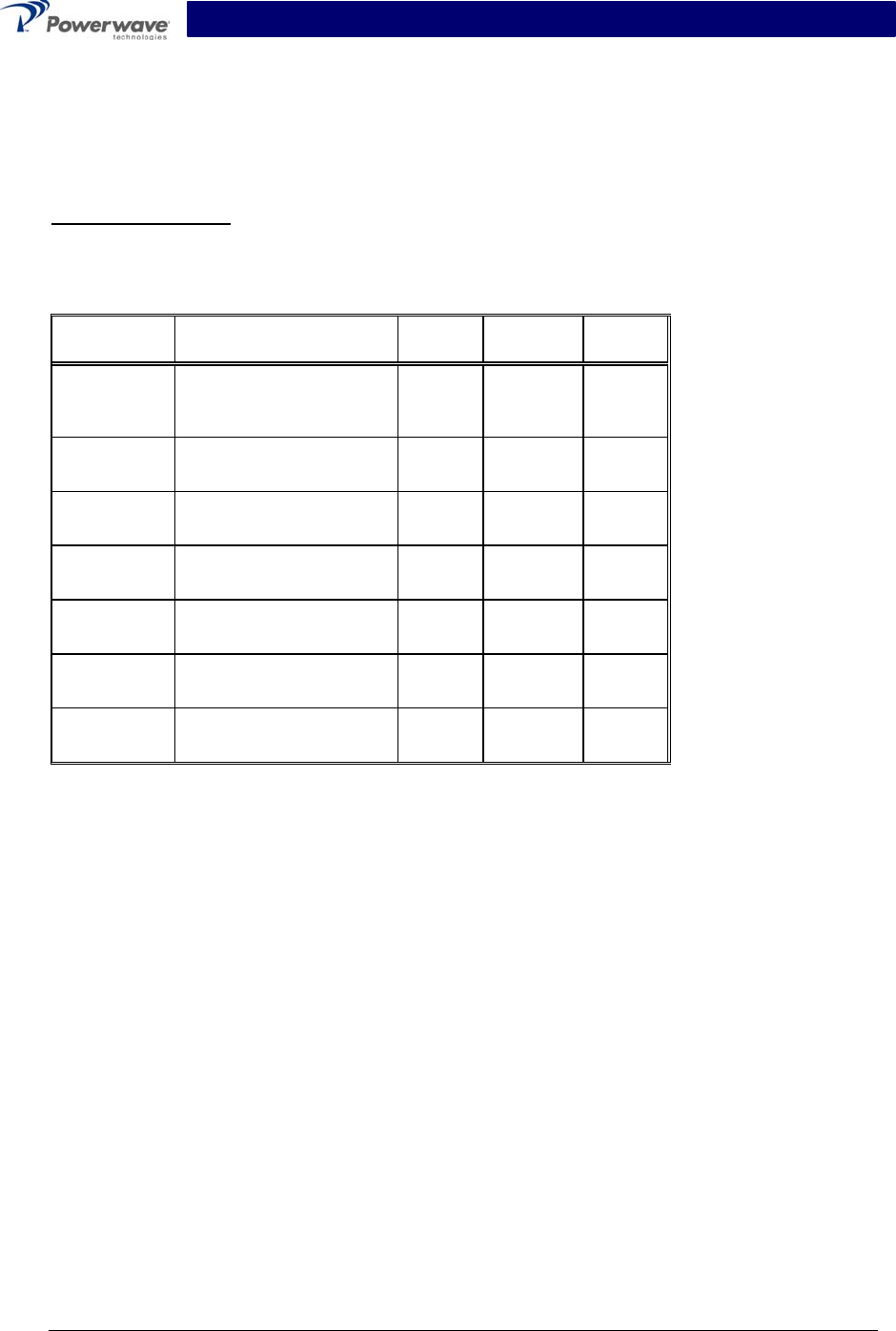
Table 5-3 Multicarrier Cellular Amplifier Test Data Sheet
DATE _________________________________
AMPLIFIER S/N _________________________
TEST CONDITIONS:
Load and Source Impedance: 50 Ohms
VSWR: < 1.2:1
Supply Voltage: +27 Vdc ±1.0 Vdc
TEST SPECIFICATION MIN MAX DATA
4-TONE IMD
Vcc = 27 Vdc
PO = 140 W
Freq.: 853, 857, 863, and 866
MHz
-60 dBc
RF Gain
Vcc = 27 Vdc
PO = 140 W
Freq. = 860 MHz
57.5 dB
58.5 dB
Gain Flatness
Vcc = 27 Vdc ±1 Vdc
PO =140 W
851-869 MHz Band
-0.5 dB
+0.5 dB
Harmonics
Vcc = 27 Vdc
PO = 140 W
851-869 MHz Band
5 dBm
Spurious
Vcc = 27 Vdc
PO =140 W
851-869 MHz Band
-60 dBc
Input Return
Loss
Vcc = 27 Vdc
PO = 140 W
851-869 MHz Band
-16 dB
DC Power
Vcc = 27 Vdc
PO = 140 W
4 Tones
70 Amps
PASS _________________________________ FAIL ______________________________
Tested by ______________________________

G3S-800-140-031 Installation & Service Manual
Copyright Powerwave Technologies, Inc., September 2001. All rights reserved
044-05095 Rev. A 5-6 September 2001
5-6 Field Replaceable Parts And Modules
The following parts and modules can be replaced in the field on site by a qualified technician with
experience maintaining RF power amplifiers and similar equipment:
1. G3S-800-140-031 power amplifier modules
2. Cooling fans
5-6.1 G3S-800-140-031 Power Amplifier Module
To replace a power amplifier module, proceed as follows:
1. Set both the RF ON On/Off/Reset switch and the power ON/OFF switch on the front panel of
the amplifier module to OFF.
2. Loosen two screws that secure amplifier module to subrack.
3. Use handle on front of module, and with a steady even pressure, pull module out of subrack.
CAUTION
When removing the amplifier from the subrack, it is very important to support the
amplifier such that the rear of the module does not suddenly drop when it disengages
from the track. A drop such as this could damage the module.
5-6.2 Cooling Fans
To replace a cooling fan, proceed as follows:
1. Remove amplifier module from subrack; see paragraph 5-6.1 preceding.
2. Loosen four snap fasteners that secure fan to amplifier module. Disconnect fan power con-
nector from amplifier module.
Install replacement in reverse order of steps 1 and 2 above.