Powerwave Technologies 5JS0056 Multi Carrier RF Power Amplifier User Manual 273678
Powerwave Technologies Inc Multi Carrier RF Power Amplifier 273678
Contents
Manual 3
G3S-800-140-031 Installation & Service Manual
Copyright Powerwave Technologies, Inc., September 2001. All rights reserved
044-05095 Rev. A 3-1 September 2001
Section 3 Operating Instructions
3-1 Introduction
This section contains operating instructions for the Multicarrier Cellular Amplifier System.
3-2 Location And Function Of Amplifier Module Controls And Indicators
Primary +27 Vdc power is applied to the amplifier via a 100-amp circuit breaker (ON-OFF) lo-
cated on the left side of the amplifier front panel.
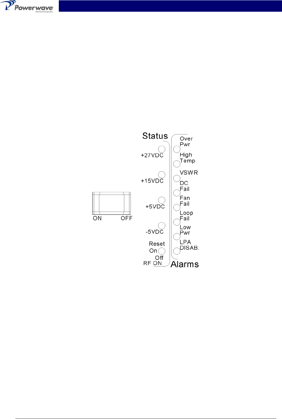
The plug-in amplifier module RF control and indicators, located in the center of the amplifier front
panel between the cooling fans, are shown in figure 3-1. The status and RF control functions and
alarms are described in detail in the subsequent paragraphs.
Figure 3-1 G3S-800-140-031 Amplifier Module RF Control and Indicators
3-2.1 Voltage Indicators And On/Off/Reset Switch
3-2.1.1 +27VDC Indicator
Green LED. When lit, indicates that the +27 Vdc supply is greater than +21 Vdc and less than
+31 Vdc. If the +27 Vdc indicator goes out, the DC FAIL indicator will illuminate. This indicates
that the +27 Vdc voltage dropped below +21 Vdc.
3-2.1.2 +15VDC Indicator
Green LED. When lit, indicates that the +15 Vdc supply is greater than +12 Vdc and less than
+17 Vdc. If the +15 Vdc indicator goes out, the DC FAIL indicator will illuminate. This indicates
that the +15 Vdc voltage dropped below +12 Vdc or increased above +17 Vdc.

G3S-800-140-031 Installation & Service Manual
Copyright Powerwave Technologies, Inc., September 2001. All rights reserved
044-05095 Rev. A 3-2 September 2001
3-2.1.3 +5VDC Indicator
Green LED. When lit, indicates that the +5 Vdc supply is greater than +2 Vdc and less than +7
Vdc. If the +5 Vdc indicator goes out, the DC FAIL indicator will illuminate. This indicates that
the +5 Vdc voltage dropped below +2 Vdc or increased above +7 Vdc.
3-2.1.4 -5VDC Indicator
Green LED. When lit, indicates that the -5 Vdc supply is greater than -7 Vdc and less than -2
Vdc. If the -5 Vdc indicator goes out, the DC FAIL indicator will illuminate. This indicates that the
-5 Vdc voltage dropped below -7 Vdc or increased above -2 Vdc.
3-2.1.5 RF ON Switch
Three position switch:
Off (down position) - Turns off amplifier module.
On (center position) - Normal amplifier on position.
Reset (up position) - When toggled to reset position, all the red LED indicators will turn on
one at a time in sequence followed by all the green indicators one at a time in sequence; this
will also reset the fault latches. If the switch is held in the reset position, a microcontroller
reset will occur. This will be verified by the LEDs toggling state again. The switch is spring
loaded to return to the normal ON position when released. If a fault occurs and the MCPA is
disabled, the alarms can be cleared and the MCPA enabled by this reset position. The func-
tions of the switch are disabled for five seconds after a power-up condition.
3-2.2 Alarm Indicators
The alarm modes described here are indicative of amplifier alarm modes made to the amplifier
subrack. The amplifier subrack interprets these alarms and may subsequently deliver a different
alarm indication to the host equipment. Refer to the amplifier subrack manual to determine host
equipment level alarms.
Refer to section 6 to interpret and correct the various alarm states.
Refer to table 3-1.
A ‘Minor Alarm’ indicates a potential fatal amplifier problem via the amplifier front panel LEDs.
and the MCPA fault will be in evaluation.
A ‘Major Alarm’ indicates a major problem but the MCPA module will not be disabled.
A ‘Critical Alarm’ is indicative of a fatal problem. The fault indicator will latch on and the MCPA
module will be disabled.
Both ‘Major Alarm’ and ‘Critical Alarm’ will be sent to the host system via the MCPA subrack.
G3S-800-140-031 Installation & Service Manual
Copyright Powerwave Technologies, Inc., September 2001. All rights reserved
044-05095 Rev. A 3-3 September 2001
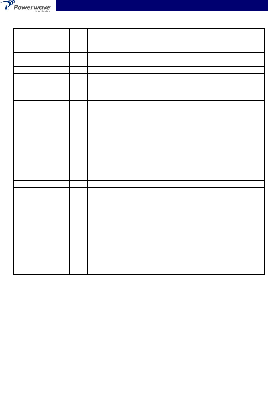
Table 3-1 Amplifier Module Alarm Indicators Definition
Alarm Mode LED
MCPA
Module
MCPA
Disable signal
(pin 4 inTable 2-1)
Condition
Over Pwr Critical Red Disable High MCPA module output power >200
watts (Note 4)
Over Pwr Critical Red Disable High Input power >-2 dBm
High Temp Minor Red Enable Low High temperature detected
High Temp Critical Red Disable High High temperature detected for longer
than two minutes
VSWR Minor Red Enable Low 14.5 W < Reflected Power < 38W
VSWR Critical Red Disable High 60W < Reflected power detected at
output longer than approx. two min.
DC Fail Minor Red Enable Low
One of the internal DC voltages
dropped below or exceeded the safe
threshold level
DC Fail Critical Red Disable High Voltage out of range for longer than
approx. two minutes (Note 2)
DC Fail
(Over
voltage)
Critical Red Disable High
+27 Vdc input >30 V for longer than
one sec. after initial detection of DC
input >31 V (Note 3)
Fan Fail
(one) Major Red Enable Low Any fan failure
Loop Fail Minor Red Enable Low Loop failure detected
Loop Fail Critical Red Disable High Loop failure detected longer than 2
minutes
Low Pwr Minor Red Enable Low
Rack controller detected MCPA out-
put is 3 dB below that of the other
MCPA in the system.
Low Pwr Critical Red Disable High
Rack controller detected low power
condition for more than approx. two
minutes
LPA
DISAB. Critical Red Disable High
Unit is manually switched off using
the front panel RF ON switch, or dis-
abled by a serial command or auto
shutdown by an alarm condition.
NOTES:
1. RS-485 serial alarm will follow LED status.
2. The appropriate status LED shall turn off indicating which voltage is out of its range.
3. When overvoltage is detected:
a) MCPA shall shut down (disable)
b) Turn on red DC Fail LED
c) Set flag for DC Fail alarm
4. When overpower is detected:
a) MCPA shall shut down (disable)
b) Turn on Over Pwr LED
c) Set flag for Over Pwr alarm
d) The MCPA module shall use a peak power detector to determine the overpower
fault.

G3S-800-140-031 Installation & Service Manual
Copyright Powerwave Technologies, Inc., September 2001. All rights reserved
044-05095 Rev. A 3-4 September 2001
3-3 Initial Start-Up And Operating Procedures
The amplifier module has two operating controls, both located on the front face of the module: the
power ON - OFF switch and the RF ON - ON/OFF/RESET switch (refer to figures 1-1 and 3-1).
To perform the initial start-up, proceed as follows:
1. Verify that all input and output cables are properly connected.
CAUTION
Before applying power, make sure that the input and output of the amplifier are prop-
erly terminated at 50 ohms. Do not operate the amplifier without a load attached.
Refer to table 1-2 for input power requirements. Excessive input power may damage
the amplifier
WARNING
Ensure the amplifier is turned off while disconnecting and reconnecting cables be-
tween the antenna interface and power measurement equipment. Failure to do so may
cause damage to the equipment or personal injury.
NOTE
The output coaxial cable between the amplifier and the antenna must be 50 ohm co-
axial cable. Use of any other cable will distort the output.
2. Verify that the amplifier front panel switches are in the OFF position.
3. Turn on supply that provides +27 Vdc to the amplifier system. Do not apply an RF signal to
the amplifier system
4. Place the ON - OFF circuit breaker on the amplifier in the ON position. Visually check the
indicators on the amplifier module, and verify that the following indicators are on:
A. LPA DISAB. indicator (red) should be on.
B. The +27VDC, +15VDC, +5VDC and -5VDC indicators (green) on the amplifier module
should be on.
5. Set the RF ON switch to the ON (center) position. All red LEDs should turn off after six sec-
onds.
6. Follow the power setting procedure set forth in the amplifier subrack or system integration
manual. Turn on external exciter/transceiver and apply RF input signals.