Powerwave Technologies 5JS0056 Multi Carrier RF Power Amplifier User Manual 273679
Powerwave Technologies Inc Multi Carrier RF Power Amplifier 273679
Contents
Manual 4

G3S-800-140-031 Installation & Service Manual
Copyright Powerwave Technologies, Inc., September 2001. All rights reserved
044-05095 Rev. A 4-1 September 2001
Section 4 Principles of Operation
4-1 Introduction
This section contains a functional description of the Multicarrier Cellular Amplifier.
4-2 RF Input Signal
The maximum input power for all carrier frequencies should not exceed the limits specified in ta-
ble 1-2. For proper amplifier loop balance, the out of band components of the input signals
should not exceed -40 dBc. The input VSWR should be 2:1 maximum (or better).
4-3 RF Output Load
The load impedance should be as good as possible (1.5:1 or better) in the working band for good
power transfer to the load. If the amplifier is operated into a filter, it will maintain its distortion
characteristics outside the signal band even if the VSWR is infinite, provided the reflected power
does not exceed one watt. A parasitic signal of less than one watt incident on the output will not
cause distortion at a higher level than the normal forward distortion (i.e. -60 dBc).
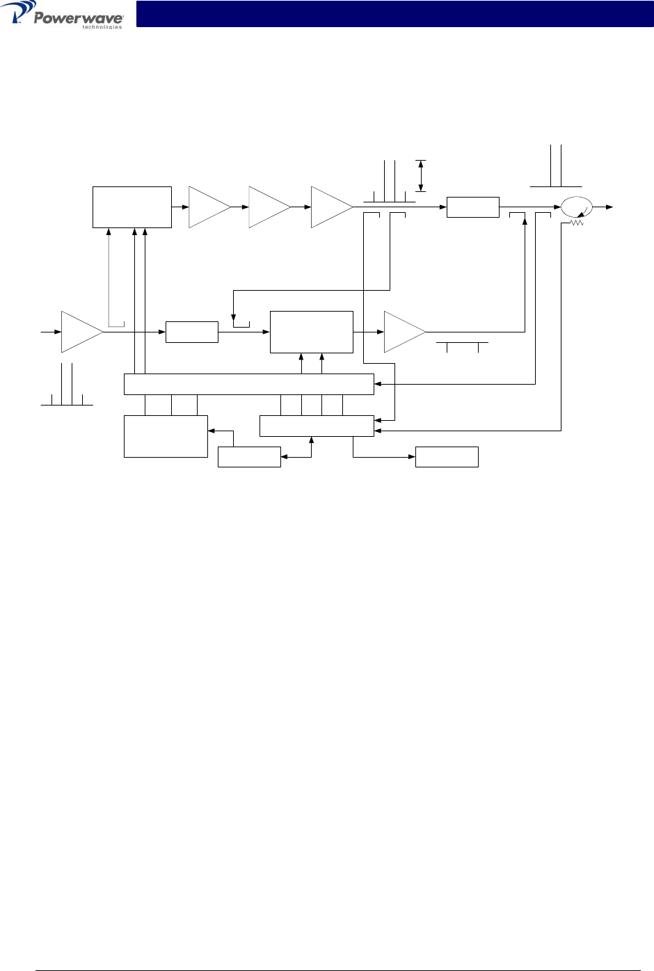
4-4 G3S-800-140-031 Amplifier Module
The G3S-800-140-031 amplifier is a linear, feed-forward power amplifier that operates in the 25
MHz frequency band from 851 MHz to 869 MHz. The amplifier modules are designed for parallel
operation to achieve high peak power output, and for redundancy in unmanned remote locations.
The amplifier module, figure 4-1, has an average output of 140 watts power (1400 watts peak
power) with intermodulation products suppressed to better than -60 dBc below carrier levels. The
amplifier provides an amplified output signal with constant gain and phase by adding approxi-
mately 30 dB of distortion cancellation on the output signal. Constant gain and phase is main-
tained by continuously comparing active paths with passive references, and correcting for small
variations through the RF feedback controls. All gain and phase variations, for example those
due to temperature, are reduced to the passive reference variations. Each amplifier module has
an alarm and display board that monitors the amplifier performance. If a failure or fault occurs in
an amplifier module, it is displayed on the individual amplifier front panel.
The amplifier module is comprised of:
Predistorter
Pre-amplifiers
Main amplifier
Error amplifier
Two feed-forward loops with phase-shift and gain controls
DC/DC power regulator
Alarm monitoring, control and display panel
The main amplifier employs class AB amplification for maximum efficiency. The error amplifier
and feed forward loops are employed to correct signal nonlinearities introduced by the class AB
main amplifier. The error amplifier operates in class AB mode. The RF input signals are ampli-
fied by a preamp and coupled to an attenuator and phase shifter in the first feed-forward loop.
The main signal is phase shifted by 180 degrees and amplified in the premain amplifier. The out-
put from the premain amplifier is fed to the class AB main amplifier. The output from the main
amplifier is typically 220 watts. The signal is output to several couplers and a delay line.
G3S-800-140-031 Installation & Service Manual
Copyright Powerwave Technologies, Inc., September 2001. All rights reserved
044-05095 Rev. A 4-2 September 2001
The signal output from the main amplifier is sampled using a coupler, and the sample signal is
combined with the main input signal and input to the second feed-forward loop. The error signal
is attenuated, phase shifted 180 degrees, then fed to the error amplifier where it is amplified to a
level identical to the sampled output from the main amplifier. The output from the error amplifier
is then coupled back and added to the output from the main amplifier. The control loops continu-
ously make adjustments to cancel out any distortion in the final output signals.
Pre
Amp
Pre
Main
Main
Amp
Error
Amp
Delay
Feed Forward Loop control
2nd Loop
Phase & Gain
1st Loop
Phase & Gain Delay
Alarms & Display
+15 +5 -5
Power Supply
-30dB -10dB
-40dB
RF Out
RFL
PWR
FWD
PWR
Front Panel
Smart Rack
+27VDC
Pre
Dist
Figure 4-1 G3S-800-140-031 Power Amplifier Module Functional Block Diagram
The 2nd loop control section obtains a sample of the distortion added to the output signals by the
main amplifiers, phase shifts the signals by 180 degrees, then feeds it to the error amplifier.
There it is amplified to the same power level as the input sample and coupled on to the main out-
put signal. The final output is monitored by the 2nd loop and adjusted to ensure that the signal
distortion and IMD on the final output is canceled out.
4-4.1 Main Amplifier
The input and output of the amplifier employ two-stage, class AB amplifiers which provide ap-
proximately 32 dB of gain in the 25 MHz frequency band from 851 to 869 MHz. The amplifier op-
erates on +27 Vdc, and a bias voltage of +5 Vdc, and is mounted directly on a heat sink that is
temperature monitored by a thermostat. If the heat sink temperature exceeds 90° C, a high tem-
perature fault occurs. The alarm logic controls the +5 Vdc bias voltage that shuts down the ampli-
fier.
4-4.2 Error Amplifier
The main function of the error amplifier is to sample and amplify the signal distortion level gener-
ated by the main amplifier, to a level that cancels out the distortion and IMD when the error signal
is coupled onto the main signal at the amplifier output. The error amplifier is a balanced multi-
stage, class AB amplifier, has 51 dB of gain, and produces up to an 80-watt output. The amplifier
operates on 27 Vdc and a bias voltage of +5 Vdc, and is mounted directly on a heat sink.
4-4.3 Amplifier Monitoring
In the main and error amplifier modules, all normal variations are automatically compensated for
by the feedforward loop control. However, when large variations occur beyond the adjustment

G3S-800-140-031 Installation & Service Manual
Copyright Powerwave Technologies, Inc., September 2001. All rights reserved
044-05095 Rev. A 4-3 September 2001
range of the loop control, a loop fault will occur. The alarms are displayed on the front panel indi-
cators and output via a 21-pin connector on the rear of the module to the subrack summary board
for subsequent remote monitoring via the ALARMS connector. Refer to paragraph 2-6 as well as
figure 2-2 and table 2-3 for a description of the ALARMS connector.
4-4.4 Amplifier Module Cooling
Although each amplifier module contains its own heat sink, it is cooled with forced air. Four fans
are used for forced air-cooling and redundancy. The fans, located on the front and rear of the
amplifier module, draw air in through the front of the amplifier and exhaust hot air out the back of
the module. The fans are field replaceable.
4-5 Power Distribution
Primary DC power for the system is provided by the host system to the MCR30829-1-3 Series
subrack. The subrack supplies each amplifier module with +27 Vdc directly and via the RF
power splitter/combiner. The amplifier module has a DC/DC converter that converts the +27 Vdc
to +15 Vdc, +5 Vdc and -5 Vdc.
4-6 Intermodulation
The G3S-800-140-031 amplifier is designed to deliver a 140-watt composite average power, mul-
ticarrier signal, occupying a bandwidth less than or equal to 18 MHz, in the bandwidth from 851
to 869 MHz. The maximum average power for linear operation, and thus the amplifier efficiency,
will depend on the type of signal amplified.
4-6.1 Two Tone Intermodulation
When measured with two equal CW tones spaced anywhere from 30 kHz to 18 MHz apart, and
at any power level up to the average power, the third order intermodulation products will be be-
low -60 dBc.
4-6.2 Multitone Intermodulation
Adding more tones to the signal will lower individual intermodulation products. If the frequencies
are not equally spaced, the level of intermodulation products gets very low. When the frequen-
cies are equally spaced, those products fall on top of each other on the same frequency grid.
The average power of all intermodulation beats falling on the same frequency is called the com-
posite intermodulation; it is -60 dBc or better.
4-7 Alarms
The presence of several plug-in amplifier alarms can be detected at the DC and logic connector
on the amplifier rear panel. Refer to table 2-3 and figure 2-2 for a description of the connector.