Quake Global 96XXCS Q4000 / QPRO Satellite Module User Manual 1135 4713G GREEN Users Guide to Q4000 QPRO
Quake Global Inc. Q4000 / QPRO Satellite Module 1135 4713G GREEN Users Guide to Q4000 QPRO
Contents
Full Manual part 1

CONFIDENTIAL
Information classified Confidential
-
Do not copy (See last page for obligations)

Document Number 1135-4713 Rev G
THIS DOCUMENT CONTAINS CONFIDENTIAL AND PROPRIETARY INFORMATION OF QUAKE GLOBAL CORPORATION. IT MAY BE USED BY RECIPIENT ONLY FOR THE
PURPOSE FOR WHICH IT WAS TRANSMITTED AND WILL BE RETURNED UPON REQUEST OR WHEN NO LONGER NEEDED BY RECIPIENT. DISCLOSURE TO
UNAUTHORIZED THIRD PARTIES OR DUPLICATION WITHOUT THE EXPRESS WRITTEN PERMISSION OF QUAKE GLOBAL IS PROHIBITED.
CONFIDENTIAL
Information classified Confidential
-
Do not copy (See last page for obligations)
User Guide to Q4000/QPRO
Document #1135-4713
Revision G
SENSITIVITY LEVEL: GREEN

User Guide to Q4000/QPRO
Document Number 1135-4713 Rev G
THIS DOCUMENT CONTAINS CONFIDENTIAL AND PROPRIETARY INFORMATION OF QUAKE GLOBAL CORPORATION. IT MAY BE USED BY RECIPIENT ONLY FOR
THE PURPOSE FOR WHICH IT WAS TRANSMITTED AND WILL BE RETURNED UPON REQUEST OR WHEN NO LONGER NEEDED BY RECIPIENT. DISCLOSURE TO
UNAUTHORIZED THIRD PARTIES OR DUPLICATION WITHOUT THE EXPRESS WRITTEN PERMISSION OF QUAKE GLOBAL IS PROHIBITED.
Page i
CONFIDENTIAL
Information classified Confidential
-
Do not copy (See last page for obligations)
Revision History
Date Revision
Number
Description
October 2010 A Initial Production Release
December 2010 B Add TIME_SYNC event with parameter which specifies the amount of
time added to real-time clock.
Add description of SMTP message handling when message is too
large.
Add description of CAN bus loading.
Add description of “dR” to save configuration parameters when they are
changed.
Add note that QCT doesn’t work with Iridium to change Turnkey
parameters.
Update DemoApp descriptions and add DemoAppFFS and
DemoAppTCP.
Add information on changed configuration parameters via the debug
menu.
Condense verbose text throughout document.
Add power down requirements.
April 2011 C Add Iridium logging information
Support for Over-the-Air Turnkey Parameters
Additional demo program for ADC
Add note about 0xE000 to 0xEFFF space for user application return
codes.
Change description of DemoAppSERIAL.
Add Quick Start Guide
Add support for Inmarsat
Add description of Network Independent Message Manager (NIMM)
July 2011 D Added additional NIMM information
Added information about debug menus
Additional configuration parameters listed for Orbcomm
October 2011 E Add sample program DemoAppRTOS
Update with recommendations from “Replicating Customer Experience”
Added debug menus
November 2011 F Fix AUX port speed parameters and add info about losing data at high
speeds
December 2011 G Formatting and language overhaul

User Guide to Q4000/QPRO
Document Number 1135-4713 Rev G
THIS DOCUMENT CONTAINS CONFIDENTIAL AND PROPRIETARY INFORMATION OF QUAKE GLOBAL CORPORATION. IT MAY BE USED BY RECIPIENT ONLY FOR
THE PURPOSE FOR WHICH IT WAS TRANSMITTED AND WILL BE RETURNED UPON REQUEST OR WHEN NO LONGER NEEDED BY RECIPIENT. DISCLOSURE TO
UNAUTHORIZED THIRD PARTIES OR DUPLICATION WITHOUT THE EXPRESS WRITTEN PERMISSION OF QUAKE GLOBAL IS PROHIBITED.
Page ii
CONFIDENTIAL
Information classified Confidential
-
Do not copy (See last page for obligations)
Table of Contents
1INTRODUCTION .......................................................................................................... 1
1.1Overview ........................................................................................................................... 1
1.2Scope ............................................................................................................................... 1
1.3Related documents ........................................................................................................... 2
1.4Contacting QUAKE ........................................................................................................... 3
2QUICK START GUIDE ................................................................................................. 4
2.1Connecting the modem ..................................................................................................... 4
2.1.1
Connecting the Q4000................................................................................................................. 4
2.1.1.1
Inserting the SIM card in the Q4000 ....................................................................................................... 7
2.1.2
Connecting the QPRO ................................................................................................................. 8
2.1.2.1
Installing the SIM card in the QPRO ....................................................................................................... 9
2.2Serial port connections ...................................................................................................... 9
2.3Antenna setup ................................................................................................................... 9
2.4Downloading code to the modem .................................................................................... 10
2.4.1
QUAKE Configuration Tool (QCT) ............................................................................................ 11
2.4.1.1
Downloading foundation code .............................................................................................................. 11
2.5Logger messages ........................................................................................................... 13
2.6Turnkey sample application ............................................................................................. 13
2.6.1
Downloading Turnkey application code ..................................................................................... 14
2.6.2
Parameters used by Turnkey: (TK_) and (QCFG_) .................................................................. 15
2.6.2.1
(TK_): Parameters unique to the Turnkey application .......................................................................... 15
2.6.2.2
(QCFG_): Foundation configuration parameters .................................................................................. 16
2.6.2.2.1
GSM/GPRS configuration parameters ........................................................................................... 16
2.6.3
Changing parameters used by Turnkey .................................................................................... 17
2.6.3.1
Setting Turnkey (TK_) parameters ....................................................................................................... 17
2.6.3.1.1
Via the MTS port ............................................................................................................................ 17
2.6.3.1.2
Via Over the Air (OTA) ................................................................................................................... 18
2.6.3.1.2.1
Sending OTA parameters via ORBCOMM .............................................................................. 18
2.6.3.1.2.2
Sending OTA parameters via Iridium ...................................................................................... 18
2.6.3.2
Setting foundation (QCFG_) parameters .............................................................................................. 20
2.6.4
Turnkey message format ........................................................................................................... 21
2.6.5
Running the Turnkey application ............................................................................................... 21
2.6.6
Turnkey Logger messages ........................................................................................................ 22
2.6.6.1
Turnkey messages at boot up .............................................................................................................. 22
2.6.6.2
Turnkey messages during transmission ............................................................................................... 23
2.7Provisioning and activation.............................................................................................. 23
2.8Powering On/Off ............................................................................................................. 24
2.8.1
Power on ................................................................................................................................... 24
2.8.2
Power off ................................................................................................................................... 25
3ANTENNA SETUP ..................................................................................................... 26
3.1Antenna recommendations ............................................................................................. 26
3.1.1
ORBCOMM ............................................................................................................................... 26
3.1.1.1
Voltage Standing Wave Ratio (VSWR) ................................................................................................. 26
3.1.1.2
ORBCOMM satellite basics .................................................................................................................. 26
3.1.1.3
ORBCOMM ground plane ..................................................................................................................... 27
3.1.2
GPS ........................................................................................................................................... 28
3.1.3
Iridium ........................................................................................................................................ 29
3.1.4
Inmarsat ..................................................................................................................................... 29

User Guide to Q4000/QPRO
Document Number 1135-4713 Rev G
THIS DOCUMENT CONTAINS CONFIDENTIAL AND PROPRIETARY INFORMATION OF QUAKE GLOBAL CORPORATION. IT MAY BE USED BY RECIPIENT ONLY FOR
THE PURPOSE FOR WHICH IT WAS TRANSMITTED AND WILL BE RETURNED UPON REQUEST OR WHEN NO LONGER NEEDED BY RECIPIENT. DISCLOSURE TO
UNAUTHORIZED THIRD PARTIES OR DUPLICATION WITHOUT THE EXPRESS WRITTEN PERMISSION OF QUAKE GLOBAL IS PROHIBITED.
Page iii
CONFIDENTIAL
Information classified Confidential
-
Do not copy (See last page for obligations)
3.1.5
GSM/GPRS ............................................................................................................................... 29
3.2Antenna grounding .......................................................................................................... 29
3.3Noise problems ............................................................................................................... 31
4ACTIVATING AND PROVISIONING THE MODEM ................................................... 32
4.1ORBCOMM ..................................................................................................................... 32
4.1.1
Activation ................................................................................................................................... 32
4.1.2
Provisioning ............................................................................................................................... 32
4.2GPRS (non-ORBCOMM modems) .................................................................................. 33
4.2.1
Activation ................................................................................................................................... 33
4.3Iridium ............................................................................................................................. 33
4.3.1
Activation ................................................................................................................................... 33
4.3.2
Provisioning ............................................................................................................................... 34
4.4Inmarsat .......................................................................................................................... 34
4.4.1
Activation ................................................................................................................................... 34
5LOGGER MESSAGES ............................................................................................... 37
5.1ORBCOMM ..................................................................................................................... 37
5.1.1
Acquire mode ............................................................................................................................ 37
5.1.2
Receive mode ............................................................................................................................ 38
5.2Iridium ............................................................................................................................. 38
5.2.1
Request signal strength ............................................................................................................. 38
5.2.2
Check modem status ................................................................................................................. 38
5.2.3
Ring Alert sequence .................................................................................................................. 38
5.2.4
Mailbox check ............................................................................................................................ 39
5.3GSM/GPRS .................................................................................................................... 39
6QUAKE COMMUNICATION PROTOCOL (QCP) ...................................................... 40
6.1Examples of QCP ........................................................................................................... 40
6.2Passthrough and Direct mode ......................................................................................... 40
7CONFIGURATION PARAMETERS ............................................................................ 42
7.1Orbcomm-specific parameters ........................................................................................ 42
7.2QUAKE Configuration Parameters (QCFG) .................................................................... 43
7.2.1
Changing QCFG parameters .................................................................................................... 45
7.2.1.1
Change via the Logger port .................................................................................................................. 45
7.2.1.2
Change via QCP on the MTS port ........................................................................................................ 45
7.2.1.3
Change via API calls from a user application ....................................................................................... 46
7.2.2
GPRS network parameters ....................................................................................................... 47
7.2.3
SMTP and POP (email) server parameters............................................................................... 47
8INSTALLING THE IAR INTEGRATED DEVELOPMENT ENVIRONMENT ............... 49
9COMMUNICATING WITH THE MODEM .................................................................... 55
9.1Sending email to the modem ........................................................................................... 55
9.1.1
ORBCOMM ............................................................................................................................... 55
9.1.2
Iridium ........................................................................................................................................ 57
9.1.3
GSM/GPRS ............................................................................................................................... 58
9.2Sending SMS messages to the modem .......................................................................... 58
10OVER THE AIR (OTA) SOFTWARE UPDATE .......................................................... 59
10.1Introduction ..................................................................................................................... 59

User Guide to Q4000/QPRO
Document Number 1135-4713 Rev G
THIS DOCUMENT CONTAINS CONFIDENTIAL AND PROPRIETARY INFORMATION OF QUAKE GLOBAL CORPORATION. IT MAY BE USED BY RECIPIENT ONLY FOR
THE PURPOSE FOR WHICH IT WAS TRANSMITTED AND WILL BE RETURNED UPON REQUEST OR WHEN NO LONGER NEEDED BY RECIPIENT. DISCLOSURE TO
UNAUTHORIZED THIRD PARTIES OR DUPLICATION WITHOUT THE EXPRESS WRITTEN PERMISSION OF QUAKE GLOBAL IS PROHIBITED.
Page iv
CONFIDENTIAL
Information classified Confidential
-
Do not copy (See last page for obligations)
10.2Application update ............................................................. Error! Bookmark not defined.
10.3Parameter update .............................................................. Error! Bookmark not defined.
10.4Foundation update ............................................................. Error! Bookmark not defined.
10.4.1
Requirements ............................................................................................................................ 59
10.4.2
Process details .......................................................................................................................... 59
10.4.3
Steps.......................................................................................................................................... 61
10.4.4
Output ........................................................................................................................................ 62
11NETWORK INDEPENDENT MESSAGE MANAGER (NIMM) .................................... 63
11.1.1
Network configuration file .......................................................................................................... 63
11.1.1.1
Default network configuration file .......................................................................................................... 63
12SAMPLE APPLICATIONS ......................................................................................... 65
12.1Accessing the QUAKE Application Programming Interface (API) .................................... 65
12.2Turnkey application ......................................................................................................... 66
12.2.1
Compiling Turnkey ..................................................................................................................... 68
12.2.2
Loading Turnkey with the QUAKE Configuration Tool (QCT) ................................................... 71
12.2.3
Running Turnkey ....................................................................................................................... 74
12.2.4
Stopping and removing Turnkey from the modem .................................................................... 76
12.2.5
Making “Hello, World!” ............................................................................................................... 80
12.2.6
Additional detail on Turnkey ...................................................................................................... 82
12.3QuickStart application ..................................................................................................... 84
12.4DemoApp applications .................................................................................................... 85
12.4.1
DemoAppGSM .......................................................................................................................... 86
12.4.2
DemoAppSERIAL ...................................................................................................................... 90
12.4.2.1
Receiving data from the AUX port ........................................................................................................ 91
12.4.2.2
Receiving data from the MTS or Logger port ........................................................................................ 93
12.4.3
DemoAppREMOTE ................................................................................................................... 98
12.4.3.1
Remotely set a relay (via email) ........................................................................................................... 99
12.4.3.2
Remotely download a file to the modem (via email) ........................................................................... 104
12.4.4
DemoAppCAN ......................................................................................................................... 107
12.4.5
DemoAppFFS .......................................................................................................................... 114
12.4.6
DemoAppTCP ......................................................................................................................... 117
12.4.7
DemoAppADC ......................................................................................................................... 121
12.4.8
DemoAppRTOS ....................................................................................................................... 124
13SATELLITE NETWORKS ......................................................................................... 130
13.1ORBCOMM network ..................................................................................................... 130
13.1.1
ORBCOMM Auto-Roaming ..................................................................................................... 131
13.2Iridium network .............................................................................................................. 132
13.2.1
Sequence of events: Mobile Originated–Short Burst Data message (MO-SBD) .................... 133
13.2.2
Sequence of events: Mobile Terminated–Short Burst Data Message (MT-SBD) ................... 133
13.3Inmarsat network .......................................................................................................... 133
14EVENT DRIVEN ARCHITECTURE .......................................................................... 135
14.1CAN_MSG ......................................................................... Error! Bookmark not defined.
14.2CELL_NET_IN_VIEW ................................................................................................... 136
14.3CONTINUE ................................................................................................................... 136
14.4COUNTER .................................................................................................................... 136
14.5DIGITAL ........................................................................................................................ 136
14.6DIGITAL_ALARM .......................................................................................................... 136
14.7GLSS_AVAILABLE ....................................................................................................... 136
14.8MSG_ACK .................................................................................................................... 136

User Guide to Q4000/QPRO
Document Number 1135-4713 Rev G
THIS DOCUMENT CONTAINS CONFIDENTIAL AND PROPRIETARY INFORMATION OF QUAKE GLOBAL CORPORATION. IT MAY BE USED BY RECIPIENT ONLY FOR
THE PURPOSE FOR WHICH IT WAS TRANSMITTED AND WILL BE RETURNED UPON REQUEST OR WHEN NO LONGER NEEDED BY RECIPIENT. DISCLOSURE TO
UNAUTHORIZED THIRD PARTIES OR DUPLICATION WITHOUT THE EXPRESS WRITTEN PERMISSION OF QUAKE GLOBAL IS PROHIBITED.
Page v
CONFIDENTIAL
Information classified Confidential
-
Do not copy (See last page for obligations)
14.9MSG_ALERT ................................................................................................................ 136
14.10MTS_DTR ..................................................................................................................... 137
14.11MSG_MID_CHANGED ................................................................................................. 137
14.12MSG_NAK .................................................................................................................... 137
14.13MSG_RCVD ................................................................................................................. 137
14.14MSG_SEND_NAK ........................................................................................................ 137
14.15NET_CLEAR ................................................................................................................. 137
14.16NMEA_SENTENCE ...................................................................................................... 137
14.17NO_EVENT .................................................................................................................. 138
14.18ORB_ANTENNA_VSWR .............................................................................................. 138
14.19POSITION_ALARM....................................................................................................... 138
14.20POSITION_FIX ............................................................................................................. 139
14.21POWER_ON ................................................................................................................. 139
14.22RX_MTS_PKT .............................................................................................................. 139
14.23RX_SER_PKT ............................................................................................................... 139
14.24SAT_IN_VIEW .............................................................................................................. 139
14.25SHUTDOWN ................................................................................................................. 139
14.26SPEED_ALARM ........................................................................................................... 140
14.27TIMER........................................................................................................................... 140
14.28TIME_SYNC ................................................................................................................. 140
14.29USER_CMD .................................................................................................................. 141
15QUAKE FIRMWARE AND APIS .............................................................................. 142
15.1ADC module (Analog to Digital Converter) .................................................................... 143
15.2APL module (Applications) ............................................................................................ 143
15.3DIO module (Digital Input/Output) ................................................................................. 143
15.4FFS module (Flash) ...................................................................................................... 144
15.5FTP module (File Transfer) ........................................................................................... 144
15.6GPS module (Global Positioning System) ..................................................................... 144
15.7TERR module (Terrestrial) ............................................................................................ 144
15.8ORBCOMM modules .................................................................................................... 144
15.9J1939 module (Controller Area Network - CAN) ............................................................ 145
15.10QCFG module (Configuration) ...................................................................................... 145
15.11QEV module (Events) ................................................................................................... 145
15.12QLM module (Logger) ................................................................................................... 145
15.13QMM module (Messages) ............................................................................................. 146
15.14SYS module (System) ................................................................................................... 146
15.15SERIAL module ............................................................................................................ 146
15.16RELAY module ............................................................................................................. 146
15.17UART module ............................................................................................................... 147
15.18UTL module (Utilities) .................................................................................................... 147
15.19VSWR module (Voltage Standing Wave Ratio) ............................................................. 147
APPENDIX A - ORBCOMM CONFIGURATION PARAMETERS .................................. 148
APPENDIX B - QUAKE’S ORBCOMM CONFIGURATION PARMS (QCFG) ................ 152
APPENDIX C - QUAKE’S IRIDIUM & INMARSAT CONFIG PARMS (QCFG) .............. 155
APPENDIX D - DEBUG AND UTILITY MENUS ............................................................. 157
APPENDIX E - SOFTWARE FILE NAMING CONVENTION .......................................... 159

User Guide to Q4000/QPRO
Document Number 1135-4713 Rev G
THIS DOCUMENT CONTAINS CONFIDENTIAL AND PROPRIETARY INFORMATION OF QUAKE GLOBAL CORPORATION. IT MAY BE USED BY RECIPIENT ONLY FOR
THE PURPOSE FOR WHICH IT WAS TRANSMITTED AND WILL BE RETURNED UPON REQUEST OR WHEN NO LONGER NEEDED BY RECIPIENT. DISCLOSURE TO
UNAUTHORIZED THIRD PARTIES OR DUPLICATION WITHOUT THE EXPRESS WRITTEN PERMISSION OF QUAKE GLOBAL IS PROHIBITED.
Page vi
CONFIDENTIAL
Information classified Confidential
-
Do not copy (See last page for obligations)
APPENDIX F - GLOSSARY OF TERMS ........................................................................ 162
16ACTIVE GRAVEYARD (WHERE TO PLACE?) ....................................................... 164
16.1DTR handling (used to be in 9.6 Working with Turnkey) ............................................... 164
17LOAD CONDITIONS ................................................................................................ 165

User Guide to Q4000/QPRO
Document Number 1135-4713 Rev G
THIS DOCUMENT CONTAINS CONFIDENTIAL AND PROPRIETARY INFORMATION OF QUAKE GLOBAL CORPORATION. IT MAY BE USED BY RECIPIENT ONLY FOR
THE PURPOSE FOR WHICH IT WAS TRANSMITTED AND WILL BE RETURNED UPON REQUEST OR WHEN NO LONGER NEEDED BY RECIPIENT. DISCLOSURE TO
UNAUTHORIZED THIRD PARTIES OR DUPLICATION WITHOUT THE EXPRESS WRITTEN PERMISSION OF QUAKE GLOBAL IS PROHIBITED.
Page vii
CONFIDENTIAL
Information classified Confidential
-
Do not copy (See last page for obligations)
List of Figures
Figure 2-1: Q4000 assembly data cable .......................................................................................................... 4
Figure 2-2: Q4000 assembly data cable components ..................................................................................... 5
Figure 2-3: Q4000 locking connector ............................................................................................................... 5
Figure 2-4: Q4000 antenna connections .......................................................................................................... 6
Figure 2-5: QPRO assembly data cable .......................................................................................................... 8
Figure 2-6: QPRO assembly data cable components...................................................................................... 8
Figure 2-7: QPRO locking connector ............................................................................................................... 9
Figure 2-8: QCT – Initial screen ..................................................................................................................... 11
Figure 2-9: QCT – Update the firmware (1) ................................................................................................... 11
Figure 2-10: QCT – Update the firmware (2) ................................................................................................. 12
Figure 2-11: QCT – Update the firmware (3) ................................................................................................. 12
Figure 2-12: Completion of successful download (using QCT) ..................................................................... 13
Figure 2-13: Sending OTA Turnkey parameters via ORBCOMM .................................................................. 18
Figure 2-14: Sending OTA Turnkey parameters via Iridium (email) .............................................................. 19
Figure 2-15: Sending OTA Turnkey parameters via Iridium (email attachment) ........................................... 19
Figure 3-1: ORBCOMM satellite pass ............................................................................................................ 27
Figure 3-2: ORBCOMM areas of radiation ..................................................................................................... 27
Figure 3-3: Ground Plane ............................................................................................................................... 28
Figure 3-4: Antennas with blocked view of sky .............................................................................................. 30
Figure 3-5: Tipped over antenna .................................................................................................................... 30
Figure 3-6: Noise - radiated and conducted ................................................................................................... 31
Figure 7-1: QCFG parameter list .................................................................................................................... 44
Figure 7-2: Using QCP to change a numeric parameter................................................................................ 46
Figure 7-3: Using QCP to change a string parameter.................................................................................... 46
Figure 8-1: IAR dongle ................................................................................................................................... 49
Figure 8-2: IAR zip file contents screen ......................................................................................................... 49
Figure 8-3: IAR unzipped files screen ............................................................................................................ 50
Figure 8-4: IAR Workbench Welcome menu ................................................................................................. 50
Figure 8-5: IAR dongle driver installation ....................................................................................................... 51
Figure 8-6: IAR Workbench installation complete .......................................................................................... 51
Figure 8-7: IAR Information screen ................................................................................................................ 52
Figure 8-8: IAR registration screen ................................................................................................................ 53
Figure 8-9: IAR MyPages screen ................................................................................................................... 54
Figure 9-1: Orbcomm email to a modem ....................................................................................................... 56
Figure 9-2: Iridium email to a modem ............................................................................................................ 57
Figure 9-3: Data file attachment for a modem-terminated message ............................................................. 57
Figure 11-1: Default network configuration file .............................................................................................. 64
Figure 12-1: The QUAKE API documentation webpage ................................................................................ 66
Figure 12-2: API_Files_and_Manual.zip ........................................................................................................ 67
Figure 12-3: Turnkey application workspace in the IAR IDE ......................................................................... 68
Figure 12-4: Project menu .............................................................................................................................. 69
Figure 12-5: A successful build of Turnkey .................................................................................................... 70
Figure 12-6: Turnkey executable files ............................................................................................................ 70
Figure 12-7: QCT - Communication port settings .......................................................................................... 72
Figure 12-8: QCT - Connection status ........................................................................................................... 72
Figure 12-9: QCT - Flash menu .................................................................................................................... 72
Figure 12-10: QCT - Application Load (browse) ........................................................................................... 73
Figure 12-11: QCT - Application Load (load) ................................................................................................ 73
Figure 12-12: QCT - Successful file download ............................................................................................. 74
Figure 12-13: Logger output of Turnkey application startup .......................................................................... 75
Figure 12-14: Entering the Debug Flash menu .............................................................................................. 77
Figure 12-15: Stopping and removing the application ................................................................................... 78

User Guide to Q4000/QPRO
Document Number 1135-4713 Rev G
THIS DOCUMENT CONTAINS CONFIDENTIAL AND PROPRIETARY INFORMATION OF QUAKE GLOBAL CORPORATION. IT MAY BE USED BY RECIPIENT ONLY FOR
THE PURPOSE FOR WHICH IT WAS TRANSMITTED AND WILL BE RETURNED UPON REQUEST OR WHEN NO LONGER NEEDED BY RECIPIENT. DISCLOSURE TO
UNAUTHORIZED THIRD PARTIES OR DUPLICATION WITHOUT THE EXPRESS WRITTEN PERMISSION OF QUAKE GLOBAL IS PROHIBITED.
Page viii
CONFIDENTIAL
Information classified Confidential
-
Do not copy (See last page for obligations)
Figure 12-16: The application was successfully removed ............................................................................. 79
Figure 12-17: Turnkey APL.c file .................................................................................................................... 80
Figure 12-18: Modify Turnkey APL.c by adding a printf statement ................................................................ 81
Figure 12-19: Logger output with "Hello, World!" ........................................................................................... 82
Figure 12-20: Turnkey main task loop............................................................................................................ 83
Figure 12-21: Selecting the QuickStart Workspace ....................................................................................... 84
Figure 12-22: QuickStart switch statement .................................................................................................... 85
Figure 12-23: DemoAppGSM - Selecting the Workspace ............................................................................ 86
Figure 12-24: DemoAppGSM - Logger output that DemoAppGSM is running ............................................. 87
Figure 12-25: DemoAppGSM - Setting the timer .......................................................................................... 88
Figure 12-26: DemoAppGSM - Processing a timeout ................................................................................... 89
Figure 12-27: DemoAppSERIAL - Selecting the Workspace ........................................................................ 90
Figure 12-28: DemoAppSERIAL - Logger output that DemoAppSERIAL is running .................................... 91
Figure 12-29: DemoAppSERIAL - AUX output of user message ................................................................. 92
Figure 12-30: DemoAppSERIAL - Setting serial port mode ......................................................................... 93
Figure 12-31: DemoAppSERIAL - Setting serial data callback function ....................................................... 94
Figure 12-32: DemoAppSERIAL - Processing incoming serial data ............................................................. 95
Figure 12-33: DemoAppSERIAL - Call to NIMM_send()............................................................................... 96
Figure 12-34: DemoAppSERIAL - Logger output of sending serial message .............................................. 97
Figure 12-35: DemoAppREMOTE - Selecting the Workspace ...................................................................... 98
Figure 12-36: DemoAppREMOTE - Set relay email to ORBCOMM modem ................................................. 99
Figure 12-37: DemoAppREMOTE - Set relay email to Iridium modem ......................................................... 99
Figure 12-38: DemoAppREMOTE - Checking GSM/GPRSPOP server ...................................................... 100
Figure 12-39: DemoAppREMOTE - Evaluating incoming message ............................................................ 101
Figure 12-40: DemoAppREMOTE - Parsing command message ............................................................... 102
Figure 12-41: DemoAppREMOTE - Logger output for set relay .................................................................. 103
Figure 12-42: DemoAppREMOTE - Remote application update email ....................................................... 104
Figure 12-43: DemoAppREMOTE - Parse incoming remote application update message ......................... 105
Figure 12-44: DemoAppREMOTE - Event for FTP Load Successful .......................................................... 106
Figure 12-45: DemoAppCAN - Selecting the Workspace ............................................................................ 108
Figure 12-46: DemoAppCAN - Initialization of J1939 .................................................................................. 109
Figure 12-47: DemoAppCAN - Allocating CAN message buffer .................................................................. 110
Figure 12-48: DemoAppCAN - Transmit J1939 data ................................................................................... 111
Figure 12-49: DemoAppCAN - Receive J1939 data .................................................................................... 112
Figure 12-50: DemoAppCAN - Logger output for engine RPM ................................................................... 113
Figure 12-51: DemoAppFFS - Selecting the Workspace ............................................................................. 114
Figure 12-52: DemoAppFFS - Logger output for initial Power On ............................................................... 115
Figure 12-53: DemoAppFFS - Logger output for next Power On ................................................................ 116
Figure 12-54: DemoAppTCP - Selecting the Workspace ............................................................................ 117
Figure 12-55: DemoAppTCP - Initialization of TCP ..................................................................................... 118
Figure 12-56: DemoAppTCP - Request for web page data ......................................................................... 119
Figure 12-57: DemoAppTCP - Web data displayed on the Logger port ...................................................... 120
Figure 12-58: DemoAppADC - Selecting the Workspace ............................................................................ 121
Figure 12-59: DemoAppADC - Definitions ................................................................................................... 122
Figure 12-60: DemoAppADC - Logger data ................................................................................................. 123
Figure 12-61: DemoAppRTOS - Selecting the Workspace ......................................................................... 124
Figure 12-62: DemoAppRTOS - initDemoRTOS (view 1)............................................................................ 125
Figure 12-63: DemoAppRTOS - initDemoRTOS (view 2)............................................................................ 126
Figure 12-64: DemoAppRTOS - Primary Demo task ................................................................................... 127
Figure 12-65: DemoAppRTOS - Secondary Demo task .............................................................................. 128
Figure 12-66: DemoAppRTOS - Logger output ........................................................................................... 129
Figure 13-1: ORBCOMM satellite network diagram ..................................................................................... 130
Figure 13-2: Iridium network diagram .......................................................................................................... 132
Figure 13-3: SkyWave's IsatData Pro network ............................................................................................ 134
Figure 15-1: Software block diagram for fully loaded modem ..................................................................... 142

User Guide to Q4000/QPRO
Document Number 1135-4713 Rev G
THIS DOCUMENT CONTAINS CONFIDENTIAL AND PROPRIETARY INFORMATION OF QUAKE GLOBAL CORPORATION. IT MAY BE USED BY RECIPIENT ONLY FOR
THE PURPOSE FOR WHICH IT WAS TRANSMITTED AND WILL BE RETURNED UPON REQUEST OR WHEN NO LONGER NEEDED BY RECIPIENT. DISCLOSURE TO
UNAUTHORIZED THIRD PARTIES OR DUPLICATION WITHOUT THE EXPRESS WRITTEN PERMISSION OF QUAKE GLOBAL IS PROHIBITED.
Page ix
CONFIDENTIAL
Information classified Confidential
-
Do not copy (See last page for obligations)
List of Tables
Table 2-1: Turnkey application parameters ................................................................................................... 15
Table 2-2: Turnkey TK_PARAM_MASK bit fields .......................................................................................... 16
Table 2-3: SMTP and POP configuration parameters ................................................................................... 17
Table 2-4: Turnkey message format .............................................................................................................. 21
Table 3-1: Ground plane - simulated ground ................................................................................................. 27
Table 3-2: Antenna wavelength and gain ...................................................................................................... 28
Table 7-1: GSM parameters ........................................................................................................................... 47
Table 7-2: SMTP parameters ......................................................................................................................... 47
Table 7-3: POP parameters ........................................................................................................................... 48
Table 9-1: SMTP and POP configuration parameters ................................................................................... 58
Table 10-1: QCFG OTA parameters ............................................................................................................. 60
Table 10-2: Common OTA status emails ....................................................................................................... 62
Table 14-1: Timer types and properties ....................................................................................................... 140
Table A-1: ORBCOMM configuration parameters ....................................................................................... 148
Table B-1: QUAKE’s ORBCOMM configuration parameters ....................................................................... 152
Table C-1: QUAKE’s Iridium and Inmarsat configuration parameters ......................................................... 155
Table E-1: File naming – Product label ........................................................................................................ 160
Table E-2: File naming – File type ............................................................................................................... 160
Table E-3: File naming – Hardware features label ....................................................................................... 161
Table E-4: File naming – File identifier ........................................................................................................ 161

User Guide to Q4000/QPRO
Document Number 1135-4713 Rev G
THIS DOCUMENT CONTAINS CONFIDENTIAL AND PROPRIETARY INFORMATION OF QUAKE GLOBAL CORPORATION. IT MAY BE USED BY
RECIPIENT ONLY FOR THE PURPOSE FOR WHICH IT WAS TRANSMITTED AND WILL BE RETURNED UPON REQUEST OR WHEN NO LONGER NEEDED
BY RECIPIENT. DISCLOSURE TO UNAUTHORIZED THIRD PARTIES OR DUPLICATION WITHOUT THE EXPRESS WRITTEN PERMISSION OF QUAKE
GLOBAL IS PROHIBITED.
Page 1
CONFIDENTIAL
Information classified Confidential
-
Do not copy (See last page for obligations)
1 Introduction
1.1 Overview
The QUAKE Q4000/QPRO is a highly configurable, dual mode solution that is ready for global
use. The Q4000/QPRO is designed to communicate with terrestrial GSM cellular network
systems when a cellular signal is available, and to slide seamlessly into its back-up mode to
communicate with a satellite system when a cellular signal is not available. The Q4000/QPRO
has additional processing power, memory, and input/outputs that allow sophisticated customer
applications to run within the modem.
1.2 Scope
This document covers the key features of the Q4000/QPRO, a description of the operating
environment, instructions for setting up the modem including the installation, editing and
downloading of ‘C’ code, as well as an overview of the software architecture of the Q4000/QPRO
modem. This interface allows programmers to prepare custom ‘C’ code applications. With use of
the tools included in the API development environment, these applications can be embedded in
the modem to take maximum advantage of the power and functionality of QUAKE products.
This manual is divided into 13 chapters and 6 appendices, which are summarized below:
Chapter 1: INTRODUCTION to the Q4000/QPRO modem contains the scope of the
document, a list of related documents and information for contacting QUAKE.
Chapter 2: QUICK START GUIDE explains how to set up the modem, activate and provision
it, and configure and run the sample Turnkey application.
Chapter 3: ANTENNA SET UP describes how to set up the satellite and GSM/GPRS
antennas for the best possible reception.
Chapter 4: ACTIVATING, PROVISIONING AND CONFIGURING THE MODEM discusses
how to set up the connections between the modem and the satellite and terrestrial networks.
Chapter 5: LOGGER MESSAGES contains a description of different types of Logger Data.
Chapter 6: QUAKE COMMUNICATIONS PROTOCOL (QCP) demonstrates the QUAKE AT
command set for communicating over the serial port with the modem.
Chapter 7: QUAKE CONFIGURATION PARAMETERS outlines the different types of
parameters and how to configure them.
Chapter 8: INSTALLING THE IAR INTEGRATED DEVELOPMENT ENVIRONMENT
discusses installation of the Integrated Development Environment.
Chapter 9: SAMPLE APPLICATIONS gives instructions on how to run short applications that
demonstrate many features of the modem.
Chapter 10: SATELLITE NETWORKS describes the ORBCOMM, Iridium and Inmarsat
networks, as well as their respective configuration parameters.

User Guide to Q4000/QPRO
Document Number 1135-4713 Rev G
THIS DOCUMENT CONTAINS CONFIDENTIAL AND PROPRIETARY INFORMATION OF QUAKE GLOBAL CORPORATION. IT MAY BE USED BY
RECIPIENT ONLY FOR THE PURPOSE FOR WHICH IT WAS TRANSMITTED AND WILL BE RETURNED UPON REQUEST OR WHEN NO LONGER NEEDED
BY RECIPIENT. DISCLOSURE TO UNAUTHORIZED THIRD PARTIES OR DUPLICATION WITHOUT THE EXPRESS WRITTEN PERMISSION OF QUAKE
GLOBAL IS PROHIBITED.
Page 2
CONFIDENTIAL
Information classified Confidential
-
Do not copy (See last page for obligations)
Chapter 11: OVER THE AIR UPDATE describes how to update the modem’s firmware
remotely using satellite and GSM.
Chapter 12: EVENT DRIVEN ARCHITECTURE discusses the various events that make up
the software architecture of the Q4000/QPRO modem.
Chapter 13: QUAKE FIRMWARE AND API’S discusses the main modules of the modem
foundation software and their interactions.
Appendix A - ORBCOMM configuration parameters
Appendix B - QUAKE’s ORBCOMM configuration parameters
(QCFG)
Appendix C - QUAKE’s Iridium & Inmarsat configuration parameters
(QCFG).
Appendix D - Debug and utility menus
Appendix E - Software file naming convention
Appendix F - Glossary of terms
CONFIDENTIALITY OBLIGATIONS.
1.3 Related documents
The following documents contain valuable information:
[1] 1135-0902, Technical Data Sheet Q4000
[2] 1137-0901, Technical Data Sheet QPRO
[3] Q4000/QPRO API Function Reference – From QUAKE Global Website
[4] 1135-4711 QUAKE Configuration Tool (QCT)
[5] 1135-4715 QUAKE Communications Protocol (QCP) User Manual
For Q4000/QPROs with an ORBCOMM satellite transceiver installed, the following ORBCOMM
documentation may assist in application development (see www.ORBCOMM.com)
[6] ORBCOMM Serial Interface Specification, Rev. G or greater
[7] ORBCOMM Gateway Customer Access Interface Specification, Rev. C or greater
[8] ORBCOMM Messaging Services Description
[9] ORBCOMM Application Development for Roaming Phase 1
For Q4000/QPROs with an Iridium satellite transceiver installed, the following Iridium
documentation may assist in application development (see www.iridium.com)
[10] Iridium SBD Developer’s Guide
[11] 4000-3000 Rev. D. AT Command Set Manual
For Q4000/QPROs with an Inmarsat satellite transceiver installed, the following Inmarsat
documentation may assist in application development (see www.skywave.com)
[12] N200_IsatData_Pro_Network_services_Overview
[13] N201_IsatData_Pro_Tateway_Web_service_User_Guide
[14] T203_IDP_100_Modem_series_developers_Guide

User Guide to Q4000/QPRO
Document Number 1135-4713 Rev G
THIS DOCUMENT CONTAINS CONFIDENTIAL AND PROPRIETARY INFORMATION OF QUAKE GLOBAL CORPORATION. IT MAY BE USED BY
RECIPIENT ONLY FOR THE PURPOSE FOR WHICH IT WAS TRANSMITTED AND WILL BE RETURNED UPON REQUEST OR WHEN NO LONGER NEEDED
BY RECIPIENT. DISCLOSURE TO UNAUTHORIZED THIRD PARTIES OR DUPLICATION WITHOUT THE EXPRESS WRITTEN PERMISSION OF QUAKE
GLOBAL IS PROHIBITED.
Page 3
CONFIDENTIAL
Information classified Confidential
-
Do not copy (See last page for obligations)
The built-in and on-line help provided by IAR Systems for their Integrated Development
Environment (IDE) are valuable references.
The API Function Reference listed above [3] is necessary for any custom ‘C’ programming
involving calls to supported API functions. It should be viewed as a companion piece to this
document. You may obtain the most current version of this document from the QUAKE Global
website at www.quakeglobal.com.
1.4 Contacting QUAKE
To contact QUAKE Global Inc. regarding the QUAKE modem development environment, API, or
other issues, please refer to the following information:
QUAKE Global
4933 Paramount Dr
San Diego CA 92123
Phone Number: (858) 277-7290
Fax Number: (858) 277-7259
Website:
www.quakeglobal.com
Email: customersupport@quakeglobal.com

User Guide to Q4000/QPRO
Document Number 1135-4713 Rev G
THIS DOCUMENT CONTAINS CONFIDENTIAL AND PROPRIETARY INFORMATION OF QUAKE GLOBAL CORPORATION. IT MAY BE USED BY
RECIPIENT ONLY FOR THE PURPOSE FOR WHICH IT WAS TRANSMITTED AND WILL BE RETURNED UPON REQUEST OR WHEN NO LONGER NEEDED
BY RECIPIENT. DISCLOSURE TO UNAUTHORIZED THIRD PARTIES OR DUPLICATION WITHOUT THE EXPRESS WRITTEN PERMISSION OF QUAKE
GLOBAL IS PROHIBITED.
Page 4
CONFIDENTIAL
Information classified Confidential
-
Do not copy (See last page for obligations)
2 Quick Start Guide
The Q4000/QPRO operates from 6VDC to 32VDC. For satellite applications, optimal
performance requires at least 10.5 VDC.
In order to communicate with the Q4000 or QPRO the following is required:
- a computer with at least one available serial port or a USB-to-serial adapter (Keyspan,
part number USA-19HS)
- a power supply capable of providing at least 3 amps at 12 V
- a Q4000 or QPRO assembly data cable
- a Q4000 or QPRO modem.
2.1 Connecting the modem
2.1.1 Connecting the Q4000
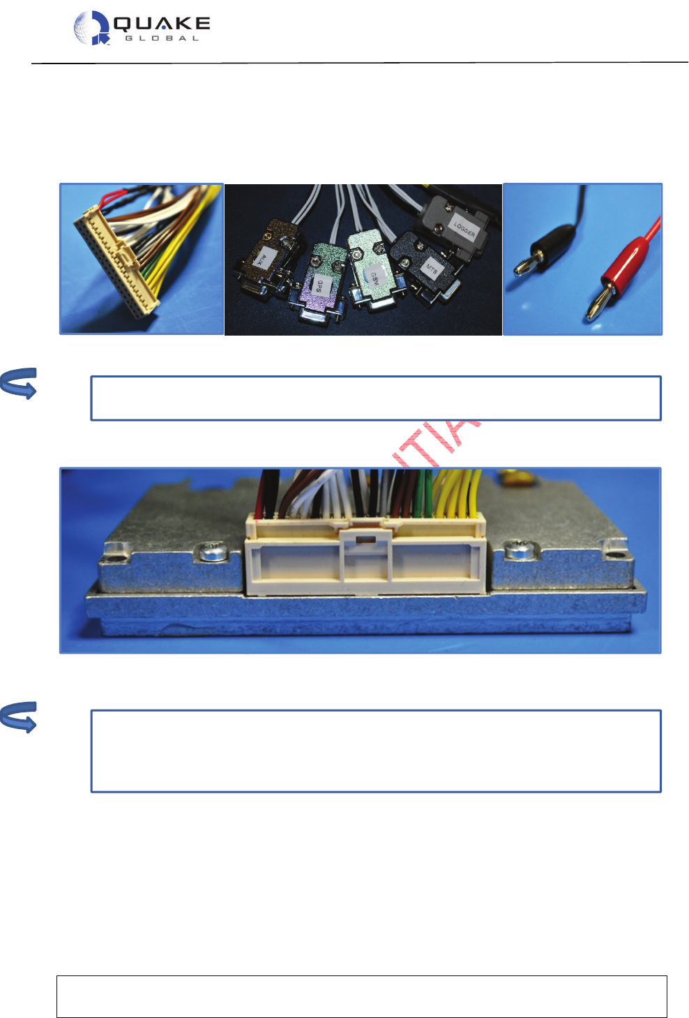
The QUAKE part number for the Q4000 assembly data cable is QUAKE P/N 1135-0211.
Figure 2-1: Q4000 assembly data cable
User Guide to Q4000/QPRO
Document Number 1135-4713 Rev G
THIS DOCUMENT CONTAINS CONFIDENTIAL AND PROPRIETARY INFORMATION OF QUAKE GLOBAL CORPORATION. IT MAY BE USED BY
RECIPIENT ONLY FOR THE PURPOSE FOR WHICH IT WAS TRANSMITTED AND WILL BE RETURNED UPON REQUEST OR WHEN NO LONGER NEEDED
BY RECIPIENT. DISCLOSURE TO UNAUTHORIZED THIRD PARTIES OR DUPLICATION WITHOUT THE EXPRESS WRITTEN PERMISSION OF QUAKE
GLOBAL IS PROHIBITED.
Page 5
CONFIDENTIAL
Information classified Confidential
-
Do not copy (See last page for obligations)
Additional serial connections, I/O, and other signal lines are also available as non-
terminated wires that come
shrink
-
wrapped together in the assembly cable.
The AUX port
•maximum speed is 57600 bps.
•may not be available on certain configurations of the Q4000. The Q4000 with
Iridium, for example, does not have the AUX port available.
There are three main components of the Q4000 assembly data cable:
1. the locking connector
2. five serial DB9 connectors for use with the Logger port, MTS, AUX, GPS and GSM)
3. power (red) and ground (black) banana plugs.
Figure 2-2: Q4000 assembly data cable components
Plug the locking connector into the modem. The connector can only fit one way as shown below.
Figure 2-3: Q4000 locking connector
Note:
Note:
User Guide to Q4000/QPRO
Document Number 1135-4713 Rev G
THIS DOCUMENT CONTAINS CONFIDENTIAL AND PROPRIETARY INFORMATION OF QUAKE GLOBAL CORPORATION. IT MAY BE USED BY
RECIPIENT ONLY FOR THE PURPOSE FOR WHICH IT WAS TRANSMITTED AND WILL BE RETURNED UPON REQUEST OR WHEN NO LONGER NEEDED
BY RECIPIENT. DISCLOSURE TO UNAUTHORIZED THIRD PARTIES OR DUPLICATION WITHOUT THE EXPRESS WRITTEN PERMISSION OF QUAKE
GLOBAL IS PROHIBITED.
Page 6
CONFIDENTIAL
Information classified Confidential
-
Do not copy (See last page for obligations)
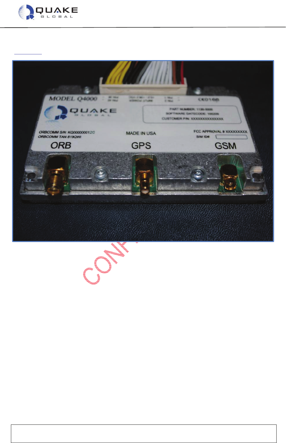
On the opposite side of the modem, attach the antenna cable to the appropriate connector
(Figure 2-4).
Figure 2-4: Q4000 antenna connections

User Guide to Q4000/QPRO
Document Number 1135-4713 Rev G
THIS DOCUMENT CONTAINS CONFIDENTIAL AND PROPRIETARY INFORMATION OF QUAKE GLOBAL CORPORATION. IT MAY BE USED BY
RECIPIENT ONLY FOR THE PURPOSE FOR WHICH IT WAS TRANSMITTED AND WILL BE RETURNED UPON REQUEST OR WHEN NO LONGER NEEDED
BY RECIPIENT. DISCLOSURE TO UNAUTHORIZED THIRD PARTIES OR DUPLICATION WITHOUT THE EXPRESS WRITTEN PERMISSION OF QUAKE
GLOBAL IS PROHIBITED.
Page 7
CONFIDENTIAL
Information classified Confidential
-
Do not copy (See last page for obligations)
2.1.1.1 Inserting the SIM card in the Q4000
One of two types of screw is used to attach the SIM card to the modem. The screw will be a
round head screw, Phillips, 0-80 X 3/16, SS, or a hex screw, size 0-80, 50
th
.
1. Find side
of case with screw and washers.
2. Remove screw and washer
s
from side of case.
3. Insert SIM card with the metal contacts
facing upward.
4. Ensure SIM card clicks into place.
5. Replace the washers and screw.
User Guide to Q4000/QPRO
Document Number 1135-4713 Rev G
THIS DOCUMENT CONTAINS CONFIDENTIAL AND PROPRIETARY INFORMATION OF QUAKE GLOBAL CORPORATION. IT MAY BE USED BY
RECIPIENT ONLY FOR THE PURPOSE FOR WHICH IT WAS TRANSMITTED AND WILL BE RETURNED UPON REQUEST OR WHEN NO LONGER NEEDED
BY RECIPIENT. DISCLOSURE TO UNAUTHORIZED THIRD PARTIES OR DUPLICATION WITHOUT THE EXPRESS WRITTEN PERMISSION OF QUAKE
GLOBAL IS PROHIBITED.
Page 8
CONFIDENTIAL
Information classified Confidential
-
Do not copy (See last page for obligations)
Additional serial connections, I/O, and other signal lines are also available as non-
terminated wires that come shrink
-
wrapped together in the assembly cable.
2.1.2 Connecting the QPRO
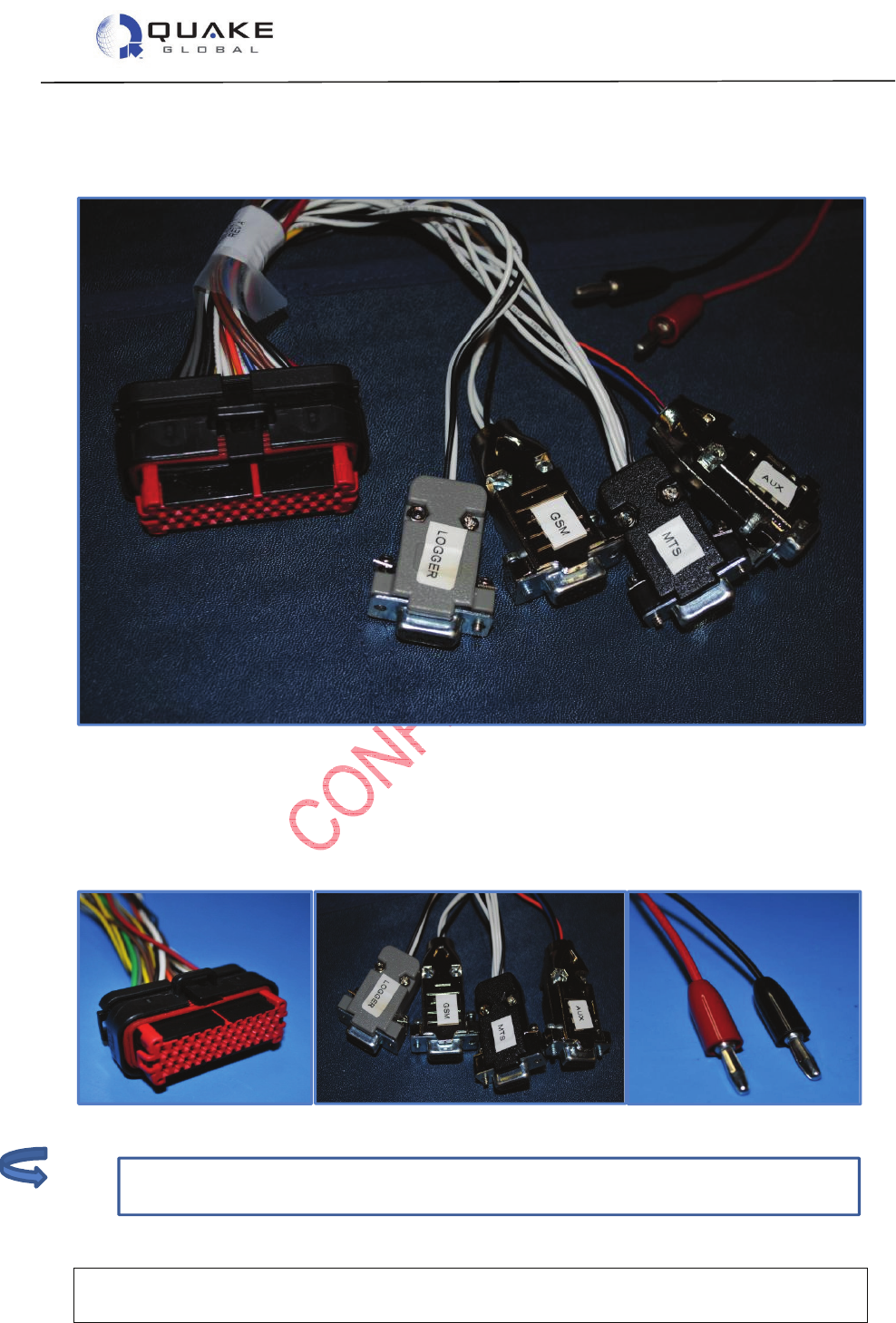
The QUAKE part number for the QPRO assembly data cable is QUAKE P/N 1137-0211.
Figure 2-5: QPRO assembly data cable
There are three main components to the QPRO assembly data cable:
1. the locking connector
2. four serial DB9 connectors for use with the Logger port, MTS, AUX, and GSM
3. power (red) and ground (black) banana plugs.
Figure 2-6: QPRO assembly data cable components
Note:

User Guide to Q4000/QPRO
Document Number 1135-4713 Rev G
THIS DOCUMENT CONTAINS CONFIDENTIAL AND PROPRIETARY INFORMATION OF QUAKE GLOBAL CORPORATION. IT MAY BE USED BY
RECIPIENT ONLY FOR THE PURPOSE FOR WHICH IT WAS TRANSMITTED AND WILL BE RETURNED UPON REQUEST OR WHEN NO LONGER NEEDED
BY RECIPIENT. DISCLOSURE TO UNAUTHORIZED THIRD PARTIES OR DUPLICATION WITHOUT THE EXPRESS WRITTEN PERMISSION OF QUAKE
GLOBAL IS PROHIBITED.
Page 9
CONFIDENTIAL
Information classified Confidential
-
Do not copy (See last page for obligations)
The AUX port:
•maximum speed is 57600 bps.
•may not be available on certain configurations of the QPRO. The QPRO with
Iridium or Inmarsat, for example, does not have the AUX port available.
Plug the locking connector into the modem. The connector can only fit one way, as shown below.
Figure 2-7: QPRO locking connector
2.1.2.1 Installing the SIM card in the QPRO
All SIM cards for the QPRO are installed by QUAKE. For a Development Kit, the SIM card
number is available on a white tag connected to the QPRO.
2.2 Serial port connections
There are four or five serial ports that come terminated with DB9 connectors:
1. the Logger port - provides diagnostic data for the user
2. the MTS port - implements QUAKE’s Communication Protocol (QCP)
3. the AUX port - can be used by application developers as they choose
4. the GSM port – used to update the GSM module firmware
5. the GPS port – streams NMEA data from the GSM module (Q4000 only).
2.3 Antenna setup
Follow the instructions in Chapter 3 - Antenna setup to install the modem’s antenna.
Note:

User Guide to Q4000/QPRO
Document Number 1135-4713 Rev G
THIS DOCUMENT CONTAINS CONFIDENTIAL AND PROPRIETARY INFORMATION OF QUAKE GLOBAL CORPORATION. IT MAY BE USED BY
RECIPIENT ONLY FOR THE PURPOSE FOR WHICH IT WAS TRANSMITTED AND WILL BE RETURNED UPON REQUEST OR WHEN NO LONGER NEEDED
BY RECIPIENT. DISCLOSURE TO UNAUTHORIZED THIRD PARTIES OR DUPLICATION WITHOUT THE EXPRESS WRITTEN PERMISSION OF QUAKE
GLOBAL IS PROHIBITED.
Page 10
CONFIDENTIAL
Information classified Confidential
-
Do not copy (See last page for obligations)
2.4 Downloading code to the modem
The Q4000/QPRO uses two separate code packages: the foundation and the application. The
foundation is supplied by QUAKE Global. The application may be written by the user or a third
party to perform operations unique to the customer’s requirements. Both can be loaded into the
modem using the QUAKE Configuration Tool (QCT).
The application code package is a loadable software file that may or may not be present in the
modem. If this file is not present, the modem acts as a simple satellite or GPRS/GSM modem
that is controlled externally via a serial interface. Alternatively, for more complex applications, a
developer can create a custom application in C code to be embedded in the modem. QUAKE
provides a number of sample applications that were developed using QUAKE’s Application
Programming Interface (API) and development environment.
The foundation code package consists of code to implement the Session, Transport and
Network layers of the satellite/terrestrial protocol. The application and the foundation are
independent tasks within the modem. The application sends and receives messages to and from
the foundation, and the foundation sends and receives messages over the RF or GPRS/GSM
links.
The modem is loaded with foundation code when it leaves the factory. New foundation code
may be obtained from the Downloads page at www.quakeglobal.com, using your assigned
username and password.

User Guide to Q4000/QPRO
Document Number 1135-4713 Rev G
THIS DOCUMENT CONTAINS CONFIDENTIAL AND PROPRIETARY INFORMATION OF QUAKE GLOBAL CORPORATION. IT MAY BE USED BY
RECIPIENT ONLY FOR THE PURPOSE FOR WHICH IT WAS TRANSMITTED AND WILL BE RETURNED UPON REQUEST OR WHEN NO LONGER NEEDED
BY RECIPIENT. DISCLOSURE TO UNAUTHORIZED THIRD PARTIES OR DUPLICATION WITHOUT THE EXPRESS WRITTEN PERMISSION OF QUAKE
GLOBAL IS PROHIBITED.
Page 11
CONFIDENTIAL
Information classified Confidential
-
Do not copy (See last page for obligations)
See Appendix E - Software file naming convention for the key to the file names.
2.4.1 QUAKE Configuration Tool (QCT)
The QUAKE Configuration Tool (QCT) provides a Graphical User Interface (GUI) to download
code and modify configuration parameters in the modem. QCT is available on the Downloads
page on the QUAKE website.
To download code or modify configuration parameters, load and run QCT on a PC connected to
the modem’s MTS serial port. When connecting to the MTS port, the default settings are:
Baud rate: 4800 bps
Data bits: 8
Parity: None
Stop bits: 1
Flow control: None
Figure 2-8: QCT – Initial screen
2.4.1.1 Downloading foundation code
If it is necessary to update the foundation (firmware) code, download the zip file from the QUAKE
Global website. After unzipping the file, you should have a foundation file with the name format of
Q4Kf-xGT-n.n.nnnn.nnn-ENC.bin.
1. In QCT, select Flash Æ
ÆÆ
ÆLoad Firmware
Figure 2-9: QCT – Update the firmware (1)
Note:
User Guide to Q4000/QPRO
Document Number 1135-4713 Rev G
THIS DOCUMENT CONTAINS CONFIDENTIAL AND PROPRIETARY INFORMATION OF QUAKE GLOBAL CORPORATION. IT MAY BE USED BY
RECIPIENT ONLY FOR THE PURPOSE FOR WHICH IT WAS TRANSMITTED AND WILL BE RETURNED UPON REQUEST OR WHEN NO LONGER NEEDED
BY RECIPIENT. DISCLOSURE TO UNAUTHORIZED THIRD PARTIES OR DUPLICATION WITHOUT THE EXPRESS WRITTEN PERMISSION OF QUAKE
GLOBAL IS PROHIBITED.
Page 12
CONFIDENTIAL
Information classified Confidential
-
Do not copy (See last page for obligations)
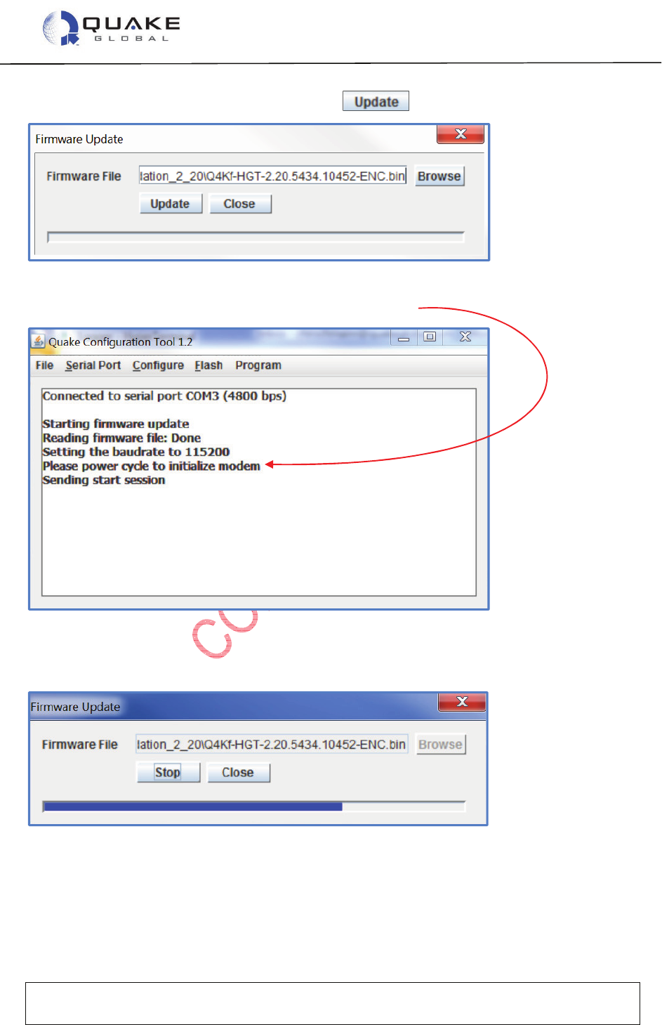
2. Enter the foundation file’s address and select .
Figure 2-10: QCT – Update the firmware (2)
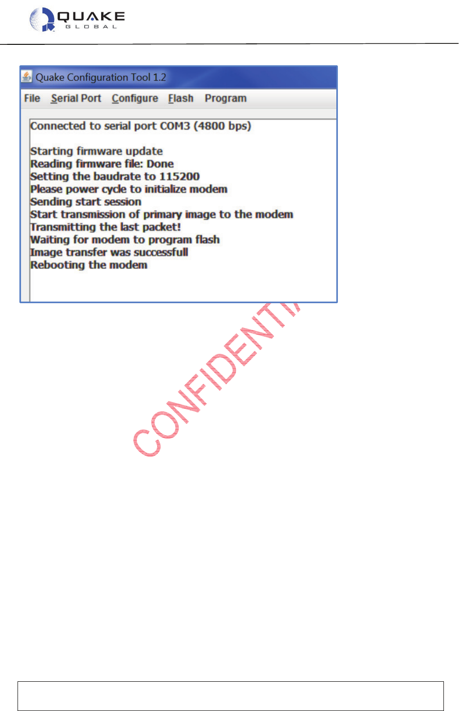
3. QCT starts the firmware update. Power cycle the modem.
Figure 2-11: QCT – Update the firmware (3)
4. The progress bar will indicate when the file is loaded.
User Guide to Q4000/QPRO
Document Number 1135-4713 Rev G
THIS DOCUMENT CONTAINS CONFIDENTIAL AND PROPRIETARY INFORMATION OF QUAKE GLOBAL CORPORATION. IT MAY BE USED BY
RECIPIENT ONLY FOR THE PURPOSE FOR WHICH IT WAS TRANSMITTED AND WILL BE RETURNED UPON REQUEST OR WHEN NO LONGER NEEDED
BY RECIPIENT. DISCLOSURE TO UNAUTHORIZED THIRD PARTIES OR DUPLICATION WITHOUT THE EXPRESS WRITTEN PERMISSION OF QUAKE
GLOBAL IS PROHIBITED.
Page 13
CONFIDENTIAL
Information classified Confidential
-
Do not copy (See last page for obligations)
Figure 2-12: Completion of successful download (using QCT)
2.5 Logger messages
All Q4000/QPRO modems have an RS-232 serial port called the Logger port. This port provides
system information so that users can monitor modem operations, and examine variables such as
satellite reception, signal strength and message status. The Logger port can be connected to any
terminal emulation program, such as Windows HyperTerminal, running on a PC.
Connect one of the PC’s terminal serial ports to the Logger serial port of the modem. If using a
serial port to USB connector, a Keyspan High-Speed USB to Serial Adapter is recommended.
Set the PC program’s parameters to the following settings:
Baud rate: 115200 bps
Data bits: 8
Parity: None
Stop bits: 1
Flow control: None
After setting up the terminal, power-up the modem with an appropriate DC power supply (12 V).
Readable ASCII text should begin to scroll down the screen and in some cases may continue
scrolling. If this has not occurred, either the serial port is not configured properly, is not
connected to the modem, or the log debug level may be set to zero.
2.6 Turnkey sample application
QUAKE Global provides a sample Turnkey application which creates a message containing the
GPS location and current values of the Digital Input/Outputs (DIOs), Analog inputs and Controller
Area Network (CAN) bus data, and then sends out the message over a network. The interval and
network used to send the message are configurable. The data sent by the message may be
User Guide to Q4000/QPRO
Document Number 1135-4713 Rev G
THIS DOCUMENT CONTAINS CONFIDENTIAL AND PROPRIETARY INFORMATION OF QUAKE GLOBAL CORPORATION. IT MAY BE USED BY
RECIPIENT ONLY FOR THE PURPOSE FOR WHICH IT WAS TRANSMITTED AND WILL BE RETURNED UPON REQUEST OR WHEN NO LONGER NEEDED
BY RECIPIENT. DISCLOSURE TO UNAUTHORIZED THIRD PARTIES OR DUPLICATION WITHOUT THE EXPRESS WRITTEN PERMISSION OF QUAKE
GLOBAL IS PROHIBITED.
Page 14
CONFIDENTIAL
Information classified Confidential
-
Do not copy (See last page for obligations)
See Appendix E - Software file naming convention for the key to the file names.
included or excluded in the message by setting bits in the message mask, but it is not possible to
add additional fields..
Turnkey can be used by customers who need a basic tracking or monitoring system. The
application requires only the configuration of message and transmission parameters in order to
run. This allows customers to use the Q4000/QPRO as an ‘out of the box’ solution.
If you have purchased an Evaluation Kit or Development Kit from QUAKE, the foundation code
and application code for Turnkey will already be installed on the modem. If not, or if you wish to
reload the modem, perform the steps in Section 2.4.
2.6.1 Downloading Turnkey application code
1. Download the latest Turnkey .bin file from the QUAKE website. After unzipping the file,
you should have a Turnkey file with the name format of Q4Ka-xGT-x.x.x.x-TurnKey.bin.
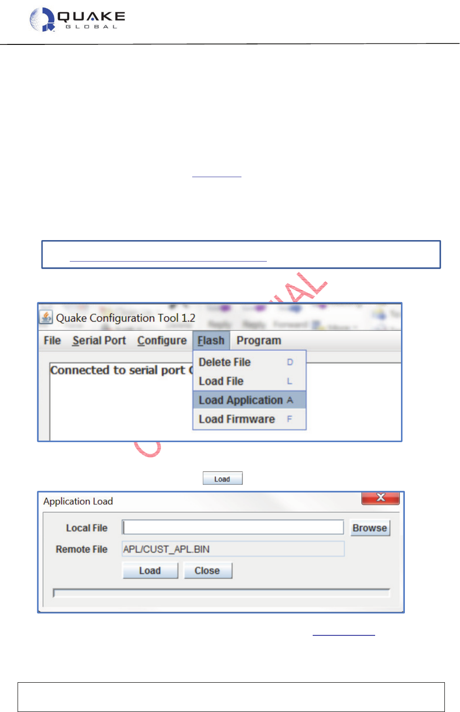
2. On the QCT screen, select Flash Æ
ÆÆ
ÆLoad Application.
A new screen will open for the application file’s address.
3. After entering the address, select .
For more information on QCT and downloading the application, see Section 12.2.2.
User Guide to Q4000/QPRO
Document Number 1135-4713 Rev G
THIS DOCUMENT CONTAINS CONFIDENTIAL AND PROPRIETARY INFORMATION OF QUAKE GLOBAL CORPORATION. IT MAY BE USED BY
RECIPIENT ONLY FOR THE PURPOSE FOR WHICH IT WAS TRANSMITTED AND WILL BE RETURNED UPON REQUEST OR WHEN NO LONGER NEEDED
BY RECIPIENT. DISCLOSURE TO UNAUTHORIZED THIRD PARTIES OR DUPLICATION WITHOUT THE EXPRESS WRITTEN PERMISSION OF QUAKE
GLOBAL IS PROHIBITED.
Page 15
CONFIDENTIAL
Information classified Confidential
-
Do not copy (See last page for obligations)
All parameters used by Turnkey (TK_ and QCFG_) may be changed whether Turnkey is
running or not. However, Turnkey must be restarted for the parameter change to take
effect.
2.6.2 Parameters used by Turnkey: (TK_) and (QCFG_)
The Turnkey application uses two different types of parameters: (TK_) and (QCFG_).
The parameters unique to the Turnkey application (TK_) are defaulted to send a message every
ten minutes. The default message will contain the current time, the GPS location, the value of the
Digital I/Os (DIOs) and analog inputs, and Parameter Group Number (PGN) information for PGN
65253. By default, the message is attempted over the GSM/GPRS network first. If that is not
successful (or available), the application sends the message over satellite (depending on the
modem type).
Turnkey also uses several QUAKE foundation configuration (QCFG_) parameters which specify
the preferred network and SMTP and POP address information (if GSM/GPRS is used).
2.6.2.1 (TK_): Parameters unique to the Turnkey application
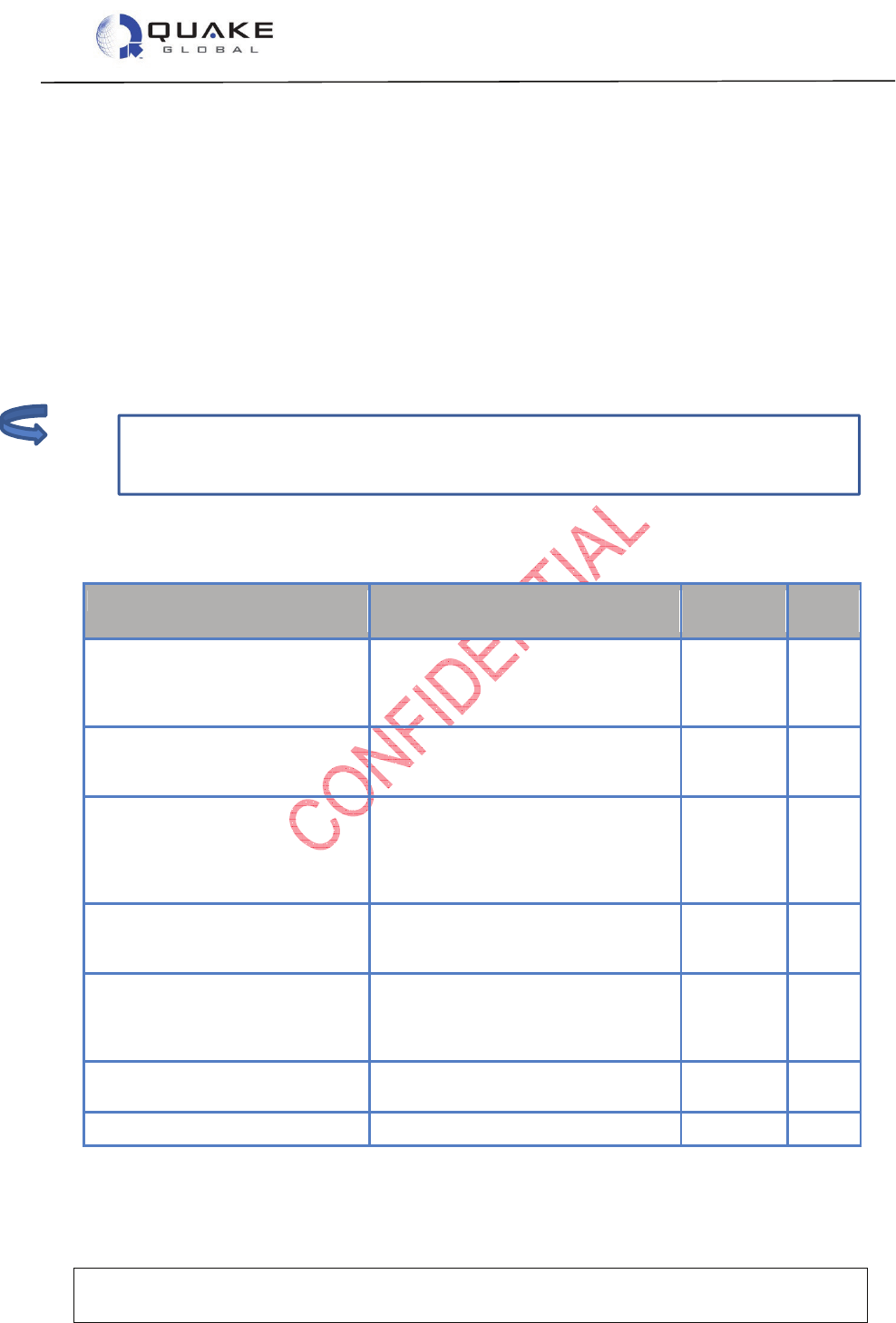
Table 2-1: Turnkey application parameters
Name
Description
Default
Value
Config
Type
TK_POWER_DOWN_AFTER_MSG
After Turnkey message is successfully
sent,
Power down modem = 1
Stay awake = 0
0 UINT8
TK_XMIT_INTERVAL
Time in seconds between successive
messages sent from modem over
GSM/GPRS or satellite.
600 UINT32
TK_RX_INTERVAL
Time in seconds between successive
message receive attempts over
GSM/GPRS.
Set to 0 to disable unsolicited POP
messages.
0 UINT32
TK_PARAM_MASK
Turnkey Parameter Mask, which controls
the fields of data included in the message
to transmit (shown in more detail below).
0xFFFFFFFF
UINT32
TK_POWER_DOWN_GSM_AFTER_MSG
After Turnkey message is successfully
sent,
Power down GSM/GPRS = 1,
Do not power down = 0.
0 UINT8
TK_ENABLE
Enable Turnkey Application = 1, Disable
Turnkey Application = 0
1 UINT8
TK_PGN0_NUMBER
PGN for desired J1939 message 65253 UINT16
Note:

User Guide to Q4000/QPRO
Document Number 1135-4713 Rev G
THIS DOCUMENT CONTAINS CONFIDENTIAL AND PROPRIETARY INFORMATION OF QUAKE GLOBAL CORPORATION. IT MAY BE USED BY
RECIPIENT ONLY FOR THE PURPOSE FOR WHICH IT WAS TRANSMITTED AND WILL BE RETURNED UPON REQUEST OR WHEN NO LONGER NEEDED
BY RECIPIENT. DISCLOSURE TO UNAUTHORIZED THIRD PARTIES OR DUPLICATION WITHOUT THE EXPRESS WRITTEN PERMISSION OF QUAKE
GLOBAL IS PROHIBITED.
Page 16
CONFIDENTIAL
Information classified Confidential
-
Do not copy (See last page for obligations)
The TK_PARAM_MASK bit fields are expanded in more detail in Table 2-2 below:
Table 2-2: Turnkey TK_PARAM_MASK bit fields
Bit Position
in Mask
Description
Default Value
1 Message counter is incremented for every
message sent while the modem is on
On
2 Julian time in seconds On
3 Latitude On
4 Longitude On
5 Altitude in meters On
6 Speed in kph On
7 Heading On
8 DIO readings On
9 Unused On
10 Value of Analog0 On
11 Value of Analog1 On
12 CAN data On
13-32 Unused On
The Turnkey parameter mask controls which fields are present in the message sent to the
network. For example, if you want only the Julian time, Latitude, Longitude, Altitude, and Speed
in your message, the value of TK_PARAM_MASK would be “0x3e” and your message size would
be 20 bytes.
2.6.2.2 (QCFG_): Foundation configuration parameters
Turnkey has several parameters which are used by the QUAKE foundation code rather than by
the Turnkey application. These QUAKE parameters control the network that Turnkey uses to
send its messages, and the SMTP and POP addresses.
The default is to attempt to send messages via GPRS, and then via the satellite network on which
the modem was activated and provisioned.
For more information on the foundation configuration parameters, see Chapter 7 - Configuration
parameters.
2.6.2.2.1 GSM/GPRS configuration parameters
If GSM/GPRS will be used to send and receive Turnkey messages, it is necessary to configure
the following SMTP and POP parameters:

User Guide to Q4000/QPRO
Document Number 1135-4713 Rev G
THIS DOCUMENT CONTAINS CONFIDENTIAL AND PROPRIETARY INFORMATION OF QUAKE GLOBAL CORPORATION. IT MAY BE USED BY
RECIPIENT ONLY FOR THE PURPOSE FOR WHICH IT WAS TRANSMITTED AND WILL BE RETURNED UPON REQUEST OR WHEN NO LONGER NEEDED
BY RECIPIENT. DISCLOSURE TO UNAUTHORIZED THIRD PARTIES OR DUPLICATION WITHOUT THE EXPRESS WRITTEN PERMISSION OF QUAKE
GLOBAL IS PROHIBITED.
Page 17
CONFIDENTIAL
Information classified Confidential
-
Do not copy (See last page for obligations)
Table 2-3: SMTP and POP configuration parameters
Name
Value (Hex)
Sample Value
s
QCFG_MODEM_APN_ADDRESS
0x9D orbcomm.t-mobile.com
QCFG_SMTP_USER 0xA6 username@gmx.com
QCFG_SMTP_PASS 0xA7 password
QCFG_POP_USER 0xAC username@gmx.com
QCFG_POP_PASS 0xAD password
QCFG_SMTP_SERVER_ADDR 0xA4 mail.gmx.com
QCFG_POP_SERVER_ADDR 0xAA pop.gmx.com
QCFG_SMTP_TO_ADDR 0xA8 username@quakeglobal.com
QCFG_SMTP_SUBJ 0xA9 This is a test subject…
2.6.3 Changing parameters used by Turnkey
A different method is used for modifying Turnkey application parameters than that used for setting
foundation parameters.
2.6.3.1 Setting Turnkey (TK_) parameters
There are a number of ways to change the default values of the Turnkey application parameters.
Two methods of changing the parameters will be shown here.
2.6.3.1.1 Via the MTS port
1. Close the QCT program if it is open, and start a Terminal Emulation program on a PC’s serial
port connected to the MTS port with the following settings:
Baud rate: 4800 bps
Data bits: 8
Parity: None
Stop bits: 1
Flow control: None
2. The command to change a parameter is:
AT+QKECA PARAMETER NAME, VALUE
For example, to change the message transmit interval to send every minute, type:
AT+QKECA TK_XMIT_INTERVAL,60
3. To examine the Turnkey settings, type:
AT+QKECA?
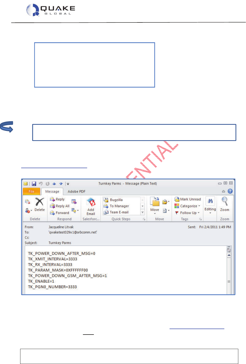
User Guide to Q4000/QPRO
Document Number 1135-4713 Rev G
THIS DOCUMENT CONTAINS CONFIDENTIAL AND PROPRIETARY INFORMATION OF QUAKE GLOBAL CORPORATION. IT MAY BE USED BY
RECIPIENT ONLY FOR THE PURPOSE FOR WHICH IT WAS TRANSMITTED AND WILL BE RETURNED UPON REQUEST OR WHEN NO LONGER NEEDED
BY RECIPIENT. DISCLOSURE TO UNAUTHORIZED THIRD PARTIES OR DUPLICATION WITHOUT THE EXPRESS WRITTEN PERMISSION OF QUAKE
GLOBAL IS PROHIBITED.
Page 18
CONFIDENTIAL
Information classified Confidential
-
Do not copy (See last page for obligations)
The SMTP and POP parameters must have been previously configured over the MTS if
using GSM/GPRS.
The following data will be displayed:
+qkeca: TK_POWER_DOWN_AFTER_MSG=0
+qkeca: TK_XMIT_INTERVAL=60
+qkeca: TK_RX_INTERVAL=0
+qkeca: TK_PARAM_MASK=4294967295
+qkeca: TK_POWER_DOWN_GSM_AFTER_MSG=0
+qkeca: TK_ENABLE=1
+qkeca: TK_PGN0_NUMBER=65263
2.6.3.1.2 Via Over the Air (OTA)
It is possible to update the Turnkey parameters by sending an email or satellite message to the
modem. The parameters can be in any order and any number of them may be updated at a time.
2.6.3.1.2.1 Sending OTA parameters via ORBCOMM
To send OTA Turnkey parameters via ORBCOMM, the “TO:” address must be in the format:
modemIDx1@orbcomm.net. The subject line of the message can be anything. The body of the
email must have the following format:
Figure 2-13: Sending OTA Turnkey parameters via ORBCOMM
2.6.3.1.2.2 Sending OTA parameters via Iridium
To send OTA Turnkey Parameters via Iridium, the “TO:” address is data@sbd.iridium.com. The
subject line of the message must be the IMEI number of the modem. You must use an
Note:
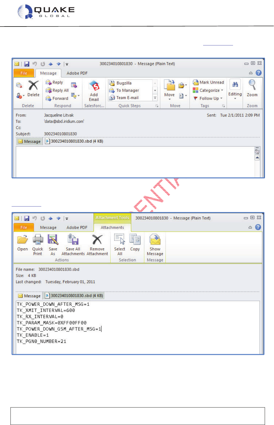
User Guide to Q4000/QPRO
Document Number 1135-4713 Rev G
THIS DOCUMENT CONTAINS CONFIDENTIAL AND PROPRIETARY INFORMATION OF QUAKE GLOBAL CORPORATION. IT MAY BE USED BY
RECIPIENT ONLY FOR THE PURPOSE FOR WHICH IT WAS TRANSMITTED AND WILL BE RETURNED UPON REQUEST OR WHEN NO LONGER NEEDED
BY RECIPIENT. DISCLOSURE TO UNAUTHORIZED THIRD PARTIES OR DUPLICATION WITHOUT THE EXPRESS WRITTEN PERMISSION OF QUAKE
GLOBAL IS PROHIBITED.
Page 19
CONFIDENTIAL
Information classified Confidential
-
Do not copy (See last page for obligations)
attachment file to specify the parameters. The body of the email is blank. Figure 2-14 is an
example of the Iridium email.
Figure 2-14: Sending OTA Turnkey parameters via Iridium (email)
Figure 2-15 is an example of the attached file.
Figure 2-15: Sending OTA Turnkey parameters via Iridium (email attachment)

User Guide to Q4000/QPRO
Document Number 1135-4713 Rev G
THIS DOCUMENT CONTAINS CONFIDENTIAL AND PROPRIETARY INFORMATION OF QUAKE GLOBAL CORPORATION. IT MAY BE USED BY
RECIPIENT ONLY FOR THE PURPOSE FOR WHICH IT WAS TRANSMITTED AND WILL BE RETURNED UPON REQUEST OR WHEN NO LONGER NEEDED
BY RECIPIENT. DISCLOSURE TO UNAUTHORIZED THIRD PARTIES OR DUPLICATION WITHOUT THE EXPRESS WRITTEN PERMISSION OF QUAKE
GLOBAL IS PROHIBITED.
Page 20
CONFIDENTIAL
Information classified Confidential
-
Do not copy (See last page for obligations)
2.6.3.2 Setting foundation (QCFG_) parameters
The Logger port can be used to change the preferred network designation and also to set the
SMTP and POP addresses.
1. Connect a Terminal Emulation program to the Logger port with the following settings:
Baud rate: 115200 bps
Data bits: 8
Parity: None
Stop bits: 1
Flow control: None
2. Type the letters: ‘U’ ‘C’ ‘s’.
3. At the prompts, type the parameter’s value in hex from Table 2-3, and then the new value.
4. The new values must be written to flash and the modem must be rebooted to save these new
values. To do this, type ‘d’ ‘R’.
5. After rebooting, Turnkey will use the new configuration parameter values.
For more information on the foundation configuration parameters, see Chapter 7 - Configuration
parameters.
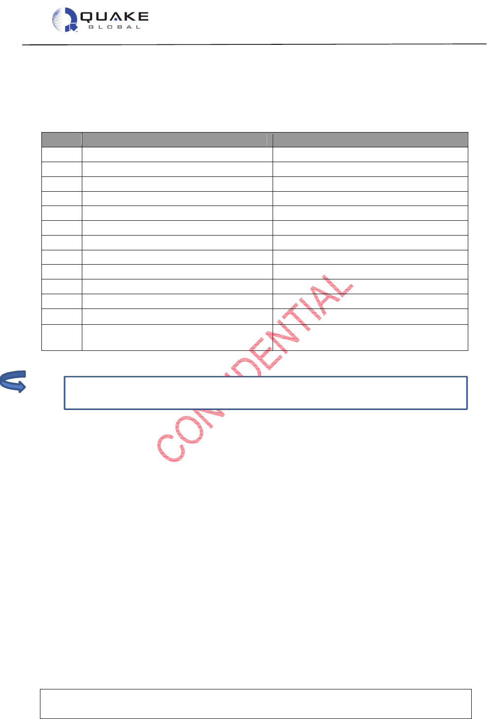
User Guide to Q4000/QPRO
Document Number 1135-4713 Rev G
THIS DOCUMENT CONTAINS CONFIDENTIAL AND PROPRIETARY INFORMATION OF QUAKE GLOBAL CORPORATION. IT MAY BE USED BY
RECIPIENT ONLY FOR THE PURPOSE FOR WHICH IT WAS TRANSMITTED AND WILL BE RETURNED UPON REQUEST OR WHEN NO LONGER NEEDED
BY RECIPIENT. DISCLOSURE TO UNAUTHORIZED THIRD PARTIES OR DUPLICATION WITHOUT THE EXPRESS WRITTEN PERMISSION OF QUAKE
GLOBAL IS PROHIBITED.
Page 21
CONFIDENTIAL
Information classified Confidential
-
Do not copy (See last page for obligations)
If the bit value in TK_PARAM_MASK is turned off, the associated bytes will not be in the
message and the message size will change.
2.6.4 Turnkey message format
The modem-originated Turnkey message has the following format if all the fields in the
TK_PARAM_MASK are set (0xFFFFFFFF):
Table 2-4: Turnkey message format
Size Field Name Description
4 messageCount message count
4 timeJS time of data collection in Julian seconds
4 gpsLatitude latitude
4 gpsLongitude longitude
4 gpsAltitude altitude in meters
4 gpsSpeed speed in kph
2 gpsHeading heading in degrees * 100
1 allDig all 8 digital inputs
1 spare0 spare input 0
4 ana0 analog0
4 ana1 analog1
2 canPgn0DataLen size of PGN0 data
1 canPgn0Data
[MAX_NUM_J1939_DATA_BYTES]
J1939 data from PGN0
2.6.5 Running the Turnkey application
The Turnkey application operates as follows:
1. At power-up, a GPS fix is started.
2. When the transmit timer expires (TK_XMIT_INTERVAL), a message with GPS and
additional configuration information (based on the contents of TK_PARAM_MASK) is sent
to the preferred network.
3. When the message has been successfully sent, the application either:
a. powers down GSM/GPRS module if TK_POWER_DOWN_GSM_AFTER_MSG is set
b. powers down the modem if TK_POWER_DOWN_AFTER_MSG is set, or
c. stays awake and attempts to transmit again after TK_XMIT_INTERVAL.
4. If the unit stays awake between transmissions, the application checks for unsolicited POP
messages every TK_RX_INTERVAL (if greater than 0).
Note:

User Guide to Q4000/QPRO
Document Number 1135-4713 Rev G
THIS DOCUMENT CONTAINS CONFIDENTIAL AND PROPRIETARY INFORMATION OF QUAKE GLOBAL CORPORATION. IT MAY BE USED BY
RECIPIENT ONLY FOR THE PURPOSE FOR WHICH IT WAS TRANSMITTED AND WILL BE RETURNED UPON REQUEST OR WHEN NO LONGER NEEDED
BY RECIPIENT. DISCLOSURE TO UNAUTHORIZED THIRD PARTIES OR DUPLICATION WITHOUT THE EXPRESS WRITTEN PERMISSION OF QUAKE
GLOBAL IS PROHIBITED.
Page 22
CONFIDENTIAL
Information classified Confidential
-
Do not copy (See last page for obligations)
2.6.6 Turnkey Logger messages
2.6.6.1 Turnkey messages at boot up
When the modem boots with the Turnkey application loaded, the current settings of the Turnkey
parameters will be displayed on the Logger port. If SMTP and POP addresses are configured,
they will be displayed also. This log information provides the dates and version numbers of the
QUAKE Turnkey and foundation code, as well as the values for Turnkey parameters and SMTP
and POP address information.
Below is a sample log file:
Copyright (C) 2010 QUAKE Global Inc.
All rights reserved. This work is the copyrighted intellectual property
of QUAKE Global Incorporated, and may not be copied, decompiled,
modified,or distributed, in whole or in part, without the express
written permission of the copyright holder. The copyright notice above
does not evidence any actual or intended publication of such source
code.
Boot Loader Version 2.1
Built at 15:01:55 on Jun 9 2010
Verifying the image...
Loading Version 1.3 of the QUAKE Foundation
Noted: 3030.10065
Product: 1, Feature: a
Starting the image
CP Code version Mar 14 2011 11:03:38
Configuring RTC...
SYS_setTime: Updated system time status (Src RTC Sync 0)
Current Time: 14Mar11 00:00:00
This unpublished source file is the copyrighted intellectual property
of QUAKE Global Incorporated, and may not be copied, decompiled,
modified, or distributed, in whole or in part, without the express
written permission of the copyright holder. The copyright notice above
does not evidence any actual or intended publication of such source
code.
THIS PRODUCT IS COVERED BY THE FOLLOWING US PATENTS: 7,289,533.
OTHER PATENTS PENDING.
UTL_nvmProtectedRead: Updating /tffs0/BACKUP/CFGMGR.CM
desired_gwy_id: 1
QUAKE Global SC #QWAKETEST029
TL Code version 1.12.1
No ETS_CHANNEL_MODES; default to elapsed times inactive.
No SMH_WRITE_INTERVAL; default to 720 seconds.
Reading 1 MSN LL elements from NVM
MSN LL[0] Gwy 1 SCT: Msg 0 980167696 Gg 0 984084496 SCO: Msg 14 Gg 1
Rpt 1
Starting customer application

User Guide to Q4000/QPRO
Document Number 1135-4713 Rev G
THIS DOCUMENT CONTAINS CONFIDENTIAL AND PROPRIETARY INFORMATION OF QUAKE GLOBAL CORPORATION. IT MAY BE USED BY
RECIPIENT ONLY FOR THE PURPOSE FOR WHICH IT WAS TRANSMITTED AND WILL BE RETURNED UPON REQUEST OR WHEN NO LONGER NEEDED
BY RECIPIENT. DISCLOSURE TO UNAUTHORIZED THIRD PARTIES OR DUPLICATION WITHOUT THE EXPRESS WRITTEN PERMISSION OF QUAKE
GLOBAL IS PROHIBITED.
Page 23
CONFIDENTIAL
Information classified Confidential
-
Do not copy (See last page for obligations)
QUAKE Turnkey APL Version Apr 1 2011, 15:16:20
Turnkey parameters may be set using the CfgMgr Utils (type U C M to
access)
Parameter names and current settings are:
TK_POWER_DOWN_AFTER_MSG 0
TK_XMIT_INTERVAL 60
TK_RX_INTERVAL 0
TK_PARAM_MASK 0xffffffff
TK_POWER_DOWN_GSM_AFTER_MSG 0
TK_ENABLE 1
TK_PGN0_NUMBER 65263
TK: ORBCOMM Modem Startup
TK: TERR Modem Startup
---accessPointName = orbcomm.t-mobile.com
---serverName = mail.gmx.com
---serverPort = 25
---smtpUser = quaketest11@gmx.com
---smtpPass = Quaketest11
---smtpToAddress = jlitvak@quakeglobal.com
---smtpDefaultSubject = Testing
---accessPointName = orbcomm.t-mobile.com
---popServerName = pop.gmx.com
---popServerPort = 110
---popUser = quaketest11@gmx.com
---popPass =
TIMER_set: Timer 0 (timerType VOLATILE) Duration 60 Secs
TIMER_set: Timer 3 (timerType VOLATILE) Duration 360 Secs
2.6.6.2 Turnkey messages during transmission
Below is an example of a Turnkey message sent over GSM/GPRS (terrestrial network). For more
information on Logger messages, see Chapter 5.
APL: TX Interval Timer - Sending message
No new GPS data
msg 1)len = 38: 0 0 0 0 97 CC D0 3A 0 0 0 0 0 0 0 0 0 0 0 0 0 0 0 0 0 0
0 0 4D D 0 0 3D D 0 0 0 0
Sending TKMsg from TERR!!!
2.7 Provisioning and activation
Upon receipt of the Q4000/QPRO, it is necessary to activate and provision the GSM/GPRS
service and/or the satellite service before using the modem to transmit messages.
• GSM/GPRS customers must obtain a SIM card from their carrier and place it into the SIM
slot located on the side of the Q4000. See Section 2.1.1.1 on how to install the SIM card.
• QPRO customers: the SIM card is installed at the factory and is inaccessible after that.
The customer may provide un-activated SIM cards to QUAKE during production and
activate them with their cellular provider upon deployment.

User Guide to Q4000/QPRO
Document Number 1135-4713 Rev G
THIS DOCUMENT CONTAINS CONFIDENTIAL AND PROPRIETARY INFORMATION OF QUAKE GLOBAL CORPORATION. IT MAY BE USED BY
RECIPIENT ONLY FOR THE PURPOSE FOR WHICH IT WAS TRANSMITTED AND WILL BE RETURNED UPON REQUEST OR WHEN NO LONGER NEEDED
BY RECIPIENT. DISCLOSURE TO UNAUTHORIZED THIRD PARTIES OR DUPLICATION WITHOUT THE EXPRESS WRITTEN PERMISSION OF QUAKE
GLOBAL IS PROHIBITED.
Page 24
CONFIDENTIAL
Information classified Confidential
-
Do not copy (See last page for obligations)
QUAKE Global evaluation and development kits include a demo account that can be activated for
at least 60 days and will allow unlimited ORBCOMM or Iridium satellite data to be sent and
received during this time. The GPRS data plan must be provisioned by the customer. Contact
customersupport@quakeglobal.com for more information on provisioning for evaluation and
development kits. Getting the demo account activated and provisioned for email usually takes
about 1 day or less once QUAKE Global receives the desired destination email address.
Initially, many users create a new email address for modem messages. It is best to set up this
new mailbox for testing purposes to avoid a flood of modem messages into your daily use email.
See Chapter 4 for more information on activating and provisioning the modem.
2.8 Powering On/Off
2.8.1 Power on
The modem can be powered on in one of three ways:
1. the application of power;
2. the Real Time Clock;
3. assert Data Terminal Ready (DTR).
A typical operating scenario for a Q4000/QPRO is to power on (wake from sleep mode), perform
a number of activities, and power off again (enter low-power sleep mode). It is important to
understand the various ways to power the Q4000/QPRO on and off.
Application of Power - When an external power source is first connected to the modem, the
device powers on, the software boots, and the device begins operation. When the modem has
powered itself down and is in sleep mode, its power consumption is low.
Real Time Clock (RTC) - The on-board Real Time Clock (RTC) may generate a signal that
causes the modem to power on from sleep mode. The RTC does not maintain the time when the
power source is removed. The time is reset when the modem establishes communication with the
first available network (GSM, GPS or Satellite Communication).
Data Terminal Ready (DTR) - If ORBCOMM configuration parameter 0x2f, pwr_dwn_mode=0, is
configured and the MTS DTR line is asserted, the unit powers up or awakens from sleep mode
(as long as power is applied). If the MTS DTR line is deasserted, the modem will initiate a
controlled power-down sequence. For Iridium and Inmarsat modems, use QCFG parameter
0xb5 (QCFG_POWER_DOWN_MODE) instead of 0x2f. See Section 7.2 for information on
changing QCFG parameters.
The DTR line has two functions:
1. It behaves as a Wakeup for the Q4000. In this functionality, a 1.8 V rise on the DTR line
will wake up the Q4000.
2. It is a normal RS-232 signal on the MTS port. During this operation of the MTS port, it
utilizes normal RS-232 levels with a 6V threshold, as specified in the Technical Data
Sheet.
The DTR line does not support CMOS levels when it is behaving as a regular RS-232 serial port.

User Guide to Q4000/QPRO
Document Number 1135-4713 Rev G
THIS DOCUMENT CONTAINS CONFIDENTIAL AND PROPRIETARY INFORMATION OF QUAKE GLOBAL CORPORATION. IT MAY BE USED BY
RECIPIENT ONLY FOR THE PURPOSE FOR WHICH IT WAS TRANSMITTED AND WILL BE RETURNED UPON REQUEST OR WHEN NO LONGER NEEDED
BY RECIPIENT. DISCLOSURE TO UNAUTHORIZED THIRD PARTIES OR DUPLICATION WITHOUT THE EXPRESS WRITTEN PERMISSION OF QUAKE
GLOBAL IS PROHIBITED.
Page 25
CONFIDENTIAL
Information classified Confidential
-
Do not copy (See last page for obligations)
2.8.2 Power off
There are a number of ways in which a controlled power-down sequence can be initiated on the
Q4000/QPRO modem:
• through a QCP call on the MTS port;
• by de-asserting the DTR line if the “power down mode” configuration parameter has been
set;
• function calls from custom applications written in ‘C’ can be used to initiate controlled power
downs from an internal application. Both QCP and the “C” programming library utilize the
function “SYS_pwrDownModem(duration)”. This command can be used to:
o power down the modem for a specific time interval;
o wake at a specific time with the use of the RTC;
o power down indefinitely and only be awakened by an external event such as
assertion of DTR or the application of power.
Please see the QCP and API reference for more details.

User Guide to Q4000/QPRO
Document Number 1135-4713 Rev G
THIS DOCUMENT CONTAINS CONFIDENTIAL AND PROPRIETARY INFORMATION OF QUAKE GLOBAL CORPORATION. IT MAY BE USED BY
RECIPIENT ONLY FOR THE PURPOSE FOR WHICH IT WAS TRANSMITTED AND WILL BE RETURNED UPON REQUEST OR WHEN NO LONGER NEEDED
BY RECIPIENT. DISCLOSURE TO UNAUTHORIZED THIRD PARTIES OR DUPLICATION WITHOUT THE EXPRESS WRITTEN PERMISSION OF QUAKE
GLOBAL IS PROHIBITED.
Page 26
CONFIDENTIAL
Information classified Confidential
-
Do not copy (See last page for obligations)
RF antennas connected to QUAKE modems should not be mounted closer than six feet
to each other. There is a risk of overpowering the receiver if two modem antennas are
moun
ted too closely to one another.
3 Antenna setup
3.1 Antenna recommendations
3.1.1 ORBCOMM
3.1.1.1 Voltage Standing Wave Ratio (VSWR)
VSWR is a measure of how well the antenna is matched to the receiver/transmitter port(s). It is a
measure of how much power is reflected from the antenna back to the transmitter output. If power
is reflected back to the transmitter, it is being lost as heat.
• 1:1 – best case. This is a perfect match between the cable and antenna.
• 1.5:1 – good.
• > 2:1 – poor match. The antenna is both not receiving signals as efficiently as possible,
and is prevented from radiating as much power as the transmitter PA is capable of
putting out.
We recommend using an antenna with less than 2:1 VSWR. Use of an antenna with larger
VSWR results in decreased messaging performance. Satisfactory operation can be achieved with
a VSWR as high as 3:1; however, message delivery latencies could be increased by 100% or
more. To determine the optimal VSWR and antenna for your specific application, we recommend
testing various antennas, cabling, and mounting options over an extended period to determine
which gives the best results.
An ORBCOMM antenna must be 50 ohm 137-150.05 MHz. Due to the fairly wide frequency
range used by ORBCOMM and the variety of installation factors between antenna size, cost, and
performance, it is not practical to achieve a VSWR of below 1.5:1 throughout the entire frequency
range. To tune an antenna to ORBCOMM frequencies, the transmit band is best at 149 MHz.
3.1.1.2 ORBCOMM satellite basics
• Direction of travel – West to East.
• Degrees of elevation – For Contiguous United States (CONUS): 85% of the time, satellite will
be between 5˚ and 45˚ elevation.
• Satellite Footprint ~ 3000 miles.
• Pass is 10 to 12 minutes for regions between 20° and 50° latitude - North and South
Hemisphere.
Note:
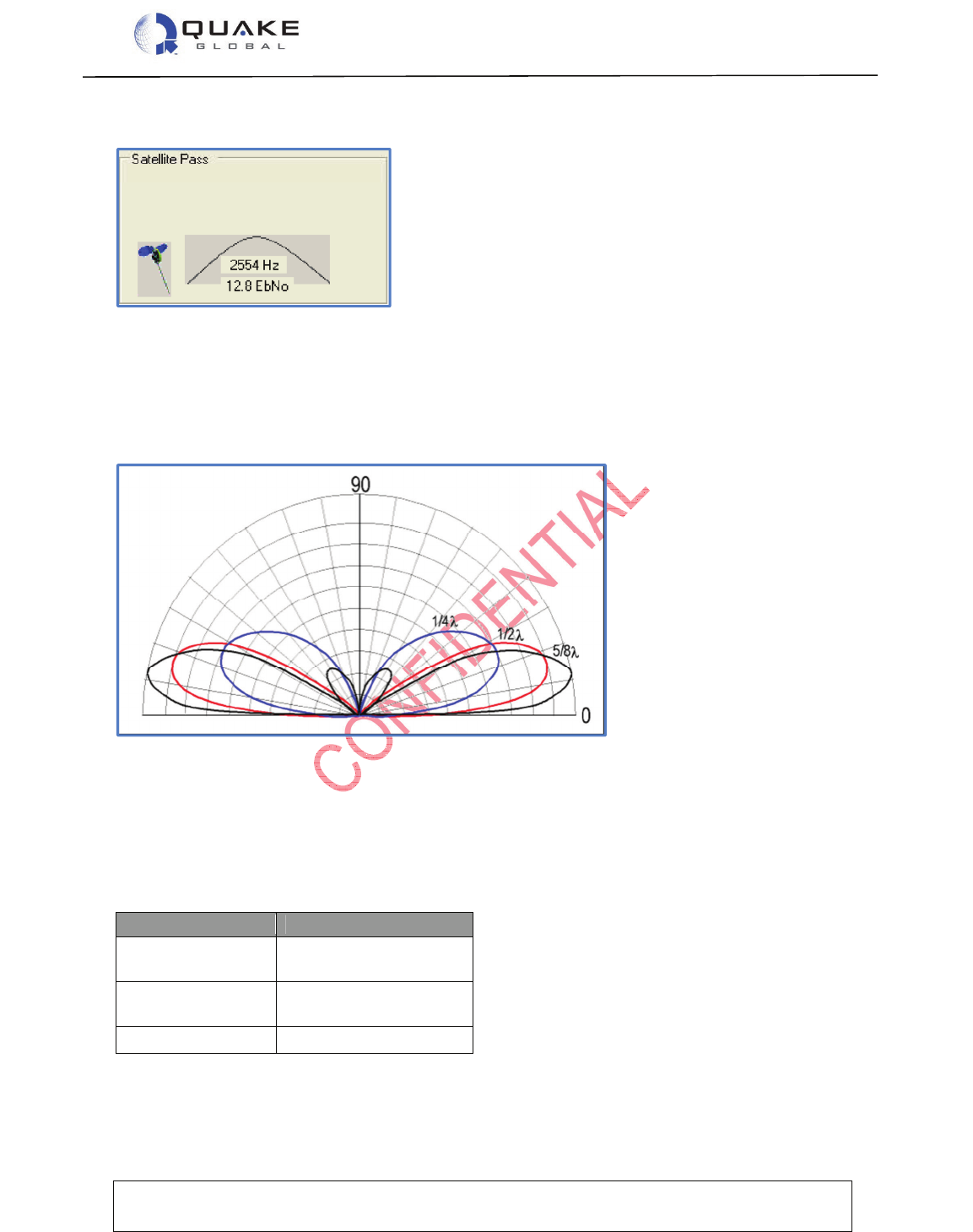
User Guide to Q4000/QPRO
Document Number 1135-4713 Rev G
THIS DOCUMENT CONTAINS CONFIDENTIAL AND PROPRIETARY INFORMATION OF QUAKE GLOBAL CORPORATION. IT MAY BE USED BY
RECIPIENT ONLY FOR THE PURPOSE FOR WHICH IT WAS TRANSMITTED AND WILL BE RETURNED UPON REQUEST OR WHEN NO LONGER NEEDED
BY RECIPIENT. DISCLOSURE TO UNAUTHORIZED THIRD PARTIES OR DUPLICATION WITHOUT THE EXPRESS WRITTEN PERMISSION OF QUAKE
GLOBAL IS PROHIBITED.
Page 27
CONFIDENTIAL
Information classified Confidential
-
Do not copy (See last page for obligations)
The figure below shows a typical Orbcomm satellite pass:
Figure 3-1: ORBCOMM satellite pass
Note that in the figure below, the area of weakest radiation is directly above 90° using a whip
antenna. The area of strongest radiation is at 1/2Ȝ. The gain increases as the angle approaches
0. The size of the ground plane affects the look angle of the antenna pattern. Maximum gain is
at 10° - 30° above ground plane. Reducing the ground plane raises the look angle vertically;
increasing the ground plane lowers the look angle horizontally.
Figure 3-2: ORBCOMM areas of radiation
3.1.1.3 ORBCOMM ground plane
The most common means of producing a low angle of radiation from an antenna is to work the
radiator against a simulated ground called a Ground Plane. A ground plane may be made from a
large metal sheet or several wires or rods radiating from the base of the radiator.
Table 3-1: Ground plane - simulated ground
Antenna Ground Plane
1/8 Whip 12” Diameter
12” x 12”
1/4 Whip 24” Diameter
24” x 24”
1/2 Wave Not required
User Guide to Q4000/QPRO
Document Number 1135-4713 Rev G
THIS DOCUMENT CONTAINS CONFIDENTIAL AND PROPRIETARY INFORMATION OF QUAKE GLOBAL CORPORATION. IT MAY BE USED BY
RECIPIENT ONLY FOR THE PURPOSE FOR WHICH IT WAS TRANSMITTED AND WILL BE RETURNED UPON REQUEST OR WHEN NO LONGER NEEDED
BY RECIPIENT. DISCLOSURE TO UNAUTHORIZED THIRD PARTIES OR DUPLICATION WITHOUT THE EXPRESS WRITTEN PERMISSION OF QUAKE
GLOBAL IS PROHIBITED.
Page 28
CONFIDENTIAL
Information classified Confidential
-
Do not copy (See last page for obligations)
Figure 3-3: Ground Plane
Table 3-2: Antenna wavelength and gain
Antenna Gain (dB)
Whip
¼, 1/2 , 5/8
Unity
(0)
1/8
-
4dB
Low Profile
-
2 to
-
4
Quad
-
Helix
+3
Dipole *
+3 to +6
3.1.2 GPS
The GPS antenna should be 3.3 VDC active. For long cable lengths, we recommend gain of 25
dB in the Low Noise Amplifier. Ensure that the GPS antenna is located so it has an unobstructed
view of the sky. Active antennas are usually low-profile patch types.
Frequency
λ
λλ
λ
/2
λ
λλ
λ
/4
137-138 MHz 2.2 m 85.9 in 42.9 in 21.5 in
148-150 MHz 2 m 79.3 in 39.6 in 19.8 in
λ
λλ
λ

User Guide to Q4000/QPRO
Document Number 1135-4713 Rev G
THIS DOCUMENT CONTAINS CONFIDENTIAL AND PROPRIETARY INFORMATION OF QUAKE GLOBAL CORPORATION. IT MAY BE USED BY
RECIPIENT ONLY FOR THE PURPOSE FOR WHICH IT WAS TRANSMITTED AND WILL BE RETURNED UPON REQUEST OR WHEN NO LONGER NEEDED
BY RECIPIENT. DISCLOSURE TO UNAUTHORIZED THIRD PARTIES OR DUPLICATION WITHOUT THE EXPRESS WRITTEN PERMISSION OF QUAKE
GLOBAL IS PROHIBITED.
Page 29
CONFIDENTIAL
Information classified Confidential
-
Do not copy (See last page for obligations)
3.1.3 Iridium
Iridium Antennas must be approved by Iridium before being used on the Iridium network. A list of
approved antennas can be found on Iridium’s home page at www.iridium.com.
When selecting an Iridium antenna, make sure it is a 50 ohm, Gain 3dBi maximum, polarization
Right Hand Circular Polarized (RHCP) and VSWR 1.5:1 or better (in both receive and transmit
bands) for optimal messaging. Make sure that the Iridium antenna is located so it has an
unobstructed view of the sky.
There cannot be more than a 3 dB loss between the antenna and the modem.
The antenna must be placed greater than 20cm from a person. If antenna is placed within 20cm
of a person, the system integrator needs to assess the final product against SAR regulation.
3.1.4 Inmarsat
There is currently one antenna version available for use, which is part number ST901009-ATY. It
is a non-standard, custom colored, external antenna with TNC connector. The antenna should be
mounted where it has an unobstructed view of the sky and satellite. For a mobile installation, this
means at the highest point on the vehicle where it has a clear view in all directions. No object
should block the antenna above a 20° elevation angle in order to ensure an optimal line of sight
with the satellite.
3.1.5 GSM/GPRS
The GSM/GPRS antenna does not require an unobstructed view of the sky. However, for optimal
performance, an unobstructed view is preferable.
GSM antenna requirements
• Gain must be less than 3dBi.
• Must be placed greater than 20cm from a person. If antenna is placed within 20cm of a
person, the system integrator needs to assess the final product against SAR regulation.
• If the antenna is co-located and transmitting simultaneously with another antenna, additional
FCC/IC testing may be required.
• Antenna cannot be placed within a metal shield and must be installed with care to avoid any
interference with other electronic devices.
3.2 Antenna grounding
Grounding may be done in several ways:
• Fixed Site: Grounding Rods should be connected to the antenna shield. Keep grounding
systems as short as possible.
• Mobile: Chassis Ground should be connected to the negative side of the battery. Make
sure all connections are corrosion free.
• Marine Grounding Systems: Skilled marine electricians should be consulted when adding
an ORBCOMM solution.
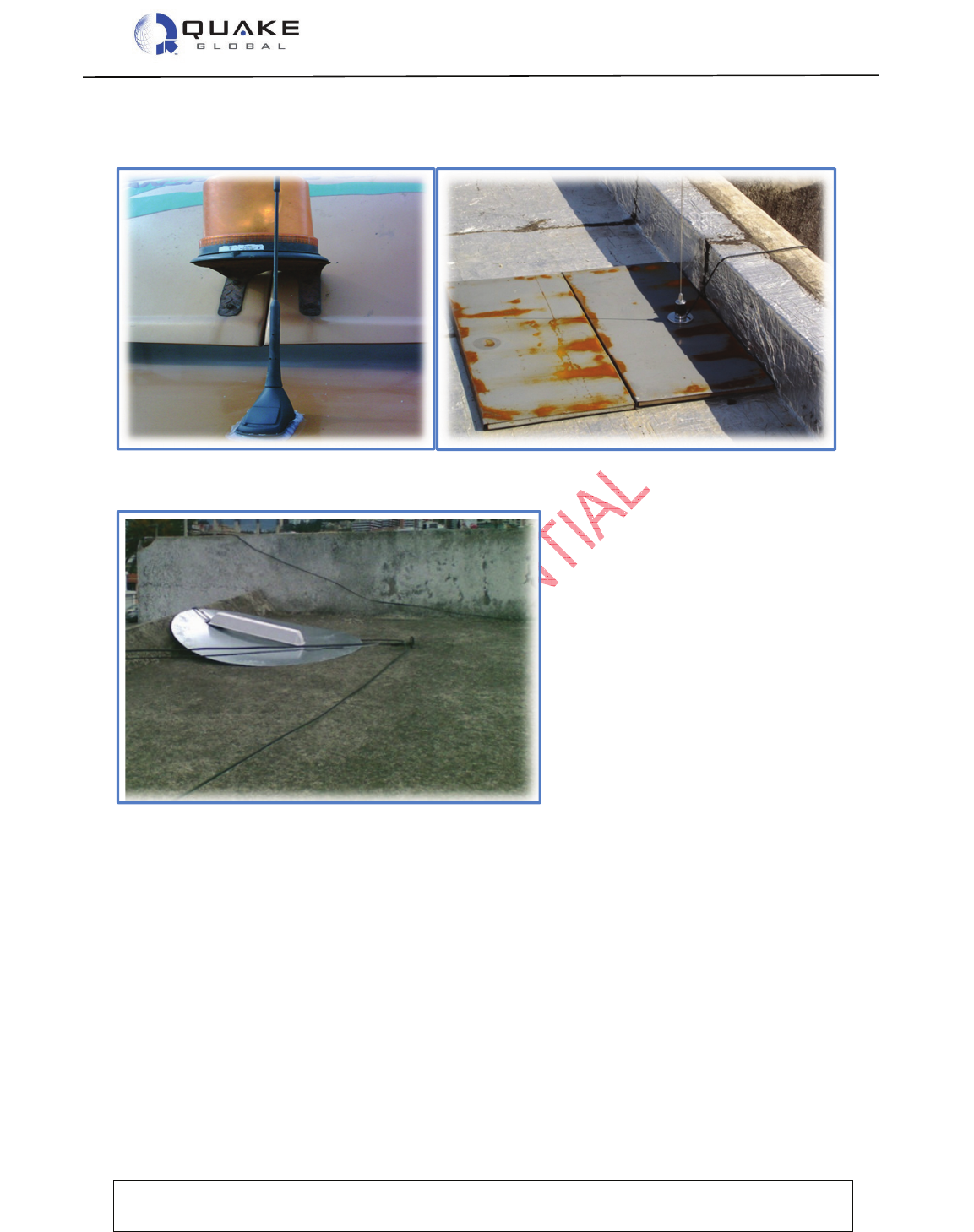
User Guide to Q4000/QPRO
Document Number 1135-4713 Rev G
THIS DOCUMENT CONTAINS CONFIDENTIAL AND PROPRIETARY INFORMATION OF QUAKE GLOBAL CORPORATION. IT MAY BE USED BY
RECIPIENT ONLY FOR THE PURPOSE FOR WHICH IT WAS TRANSMITTED AND WILL BE RETURNED UPON REQUEST OR WHEN NO LONGER NEEDED
BY RECIPIENT. DISCLOSURE TO UNAUTHORIZED THIRD PARTIES OR DUPLICATION WITHOUT THE EXPRESS WRITTEN PERMISSION OF QUAKE
GLOBAL IS PROHIBITED.
Page 30
CONFIDENTIAL
Information classified Confidential
-
Do not copy (See last page for obligations)
Beware of high power antennas, urban canyons and other structures that block the line of sight
(LOS) to the satellite. Below are some antenna installation mishaps:
Figure 3-4: Antennas with blocked view of sky
Figure 3-5: Tipped over antenna
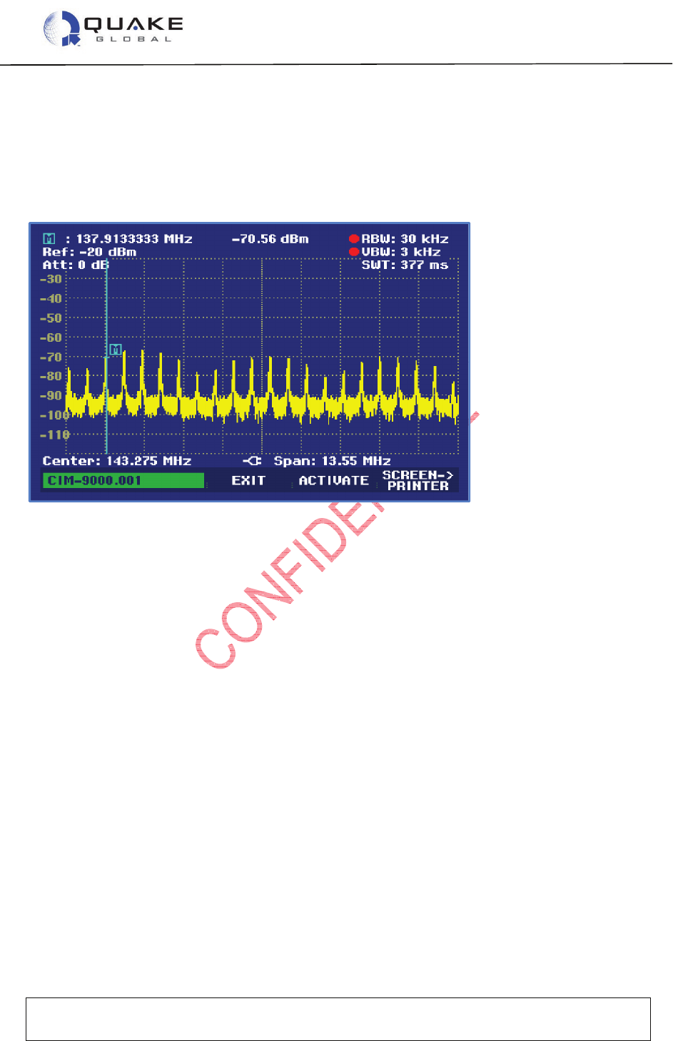
User Guide to Q4000/QPRO
Document Number 1135-4713 Rev G
THIS DOCUMENT CONTAINS CONFIDENTIAL AND PROPRIETARY INFORMATION OF QUAKE GLOBAL CORPORATION. IT MAY BE USED BY
RECIPIENT ONLY FOR THE PURPOSE FOR WHICH IT WAS TRANSMITTED AND WILL BE RETURNED UPON REQUEST OR WHEN NO LONGER NEEDED
BY RECIPIENT. DISCLOSURE TO UNAUTHORIZED THIRD PARTIES OR DUPLICATION WITHOUT THE EXPRESS WRITTEN PERMISSION OF QUAKE
GLOBAL IS PROHIBITED.
Page 31
CONFIDENTIAL
Information classified Confidential
-
Do not copy (See last page for obligations)
3.3 Noise problems
To locate noise problems, start with a visual inspection of RF connectors. Look for water leakage
or corrosion. A spectrum analyzer, VSWR meter or noise detector is helpful for locating
problems. Noise sources for broadband may be electric power lines, electric motors or
generators, switching power sources or microprocessors. Noise sources for narrowband may be
radio/TV towers, pager transmitters or cell phones.
Figure 3-6: Noise - radiated and conducted
Noise suppression parts include ferrite beads, EMI cores and RF filters. Techniques include
twisting power lines, separating power from signal, using right angles, covering the band of
interest and double wrapping wire and placing it near the noise source.

User Guide to Q4000/QPRO
Document Number 1135-4713 Rev G
THIS DOCUMENT CONTAINS CONFIDENTIAL AND PROPRIETARY INFORMATION OF QUAKE GLOBAL CORPORATION. IT MAY BE USED BY
RECIPIENT ONLY FOR THE PURPOSE FOR WHICH IT WAS TRANSMITTED AND WILL BE RETURNED UPON REQUEST OR WHEN NO LONGER NEEDED
BY RECIPIENT. DISCLOSURE TO UNAUTHORIZED THIRD PARTIES OR DUPLICATION WITHOUT THE EXPRESS WRITTEN PERMISSION OF QUAKE
GLOBAL IS PROHIBITED.
Page 32
CONFIDENTIAL
Information classified Confidential
-
Do not copy (See last page for obligations)
The modem cannot transmit until the serial ID is activated with ORBCOMM. Attempting
to use the modem before it is activated by ORBCOMM may cause the modem to be shut
out of the ORBCOMM network for 24 hours.
4 Activating and provisioning the modem
Each Q4000/QPRO must be provisioned and activated on the network(s) supported by the
modem. Modems purchased with QUAKE Global Development Kits are supplied with two
months of free airtime on the ORBCOMM or Iridium satellite networks. Otherwise, the customer
is responsible for activating and provisioning the modem(s). The following information is required
for provisioning and activation.
4.1 ORBCOMM
4.1.1 Activation
The Q4000/QPRO uses a serial ID for activation with the ORBCOMM network. This 12-digit
number is located on the Q4000’s external white label, and is also available by querying
configuration parameter 0x31 via the QUAKE Configuration Tool (QCT) interface (see below).
Contact ORBCOMM to activate the Serial ID. You will also need the Type Approval Number
(TAN), located on the white label (819QWI).
4.1.2 Provisioning
An ORBCOMM modem is provisioned by specifying the following selections to ORBCOMM
customer support:
Roaming and Gateway Earth Station - A modem must be provisioned on every ORBCOMM
Gateway that it uses. If the modem needs to send messages over multiple Gateways, it must be
provisioned on each of those Gateways.
Location Type – The location type determines how the ORBCOMM Gateway delivers messages
to the modem.
• “Fixed” - for fixed installations or modems limited to a metropolitan area.
• “Regional Mobile” - for modems that range over a wider but still limited area—like the
Southeastern United States or the Iberian Peninsula.
• “Mobile” - for modems that may be found almost anywhere across a continent.
Binary Data in Globalgrams - User applications must be specially provisioned to send binary
data in
Globalgrams.
Addressing – An SMTP email address is assigned to each modem based on its Serial ID.
Modems that are accessed via the IP gateway also have a valid SMTP email address.
PIN Code - If a Personal Identification Number (PIN) is used, it must be specified when the
modem is provisioned. The PIN code is also programmed into the modem and is verified during
most communications between the Gateway and the modem.
Note:

User Guide to Q4000/QPRO
Document Number 1135-4713 Rev G
THIS DOCUMENT CONTAINS CONFIDENTIAL AND PROPRIETARY INFORMATION OF QUAKE GLOBAL CORPORATION. IT MAY BE USED BY
RECIPIENT ONLY FOR THE PURPOSE FOR WHICH IT WAS TRANSMITTED AND WILL BE RETURNED UPON REQUEST OR WHEN NO LONGER NEEDED
BY RECIPIENT. DISCLOSURE TO UNAUTHORIZED THIRD PARTIES OR DUPLICATION WITHOUT THE EXPRESS WRITTEN PERMISSION OF QUAKE
GLOBAL IS PROHIBITED.
Page 33
CONFIDENTIAL
Information classified Confidential
-
Do not copy (See last page for obligations)
Issue QCP command TERR_getInfo() to obtain this info.
Delivery plan – Delivery plan details how ORBCOMM attempts to deliver messages to the
modem. There are 4 different Delivery Plans:
1. Automatic delivery attempts: the number of times immediately upon receipt and at
one-minute intervals that the ORBCOMM Gateway attempts to deliver a modem-
terminated message.
2. Time to hold: the maximum time the ORBCOMM Gateway holds the message before
returning it as undeliverable.
3. Deletion after final attempt: whether the message is deleted after the automatic
delivery attempts are exhausted, or held until the time to hold has been reached.
4. Use of piggybacking: whether a message delivery attempt should be triggered by
successful delivery of another message in either direction.
IP Gateway - The modem may be activated to use an XML gateway in which data are transferred
directly between servers using standard HTTP requests and XML responses instead of email.
Speed Dials - Each serial ID may be provisioned with up to eight email addresses known as
speed dials or originator/recipient (O/R) addresses.
SIM Card Number - If the modem supports GSM/GPRS, you must also specify the SIM card
number to ORBCOMM. This 19 digit number is located on the attached SIM card (use all
numbers minus the ‘F’ at the end).
4.2 GPRS (non-ORBCOMM modems)
4.2.1 Activation
GPRS SIM cards may be activated using any GSM/GPRS provider with an applicable data plan.
The data plan must use APN addressing for the modem and must support data transfer. For
example, ORBCOMM’s T-Mobile APN address is “orbcomm.t-mobile.com”. Different networks
have their own requirements for APN addressing, usernames and passwords. Please consult
your airtime reseller for more information on using the GPRS network.
4.3 Iridium
4.3.1 Activation
The modem has an IMEI number for activation with the Iridium network. This number is located
on the modem’s white label, and is also available via QUAKE Communications Protocol (QCP)
(see below), with the call “IRI_getIMEIQCP” and through the Application Programming Interface
(API) with the call “IRI_getIMEI”.
The IMEI number must be activated with Iridium or an airtime reseller before the modem can be
used. If a message is sent without the modem being activated, it is ignored by the Iridium
network. For this reason, it is possible to develop and send live messages without the modem
being “turned off” by the network.
Note: