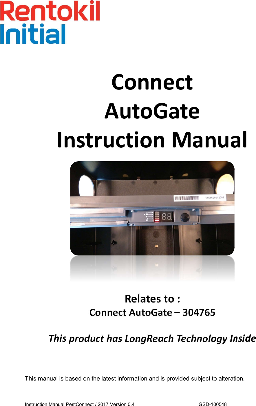
Rentokil Initial 1927 plc GSD-500349 LongReach Radio Module User Manual AutoGate Connect
Rentokil Initial 1927 plc LongReach Radio Module Users Manual AutoGate Connect
Contents
- 1. Users Manual - Control Panel
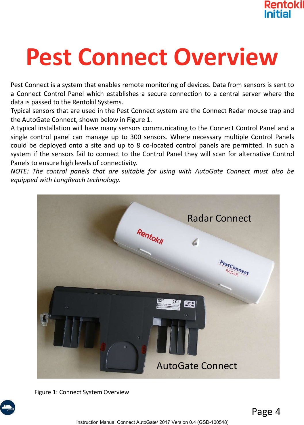
- 2. Users Manual - AutoGate Connect
- 3. Users Manual - Connect Radar
- 4. Users Manual - MMT
- 5. User Manual
- 6. User manual
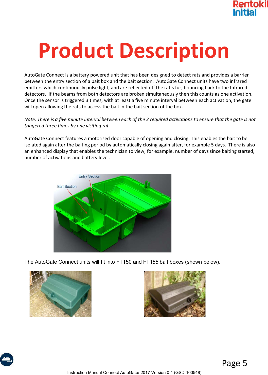
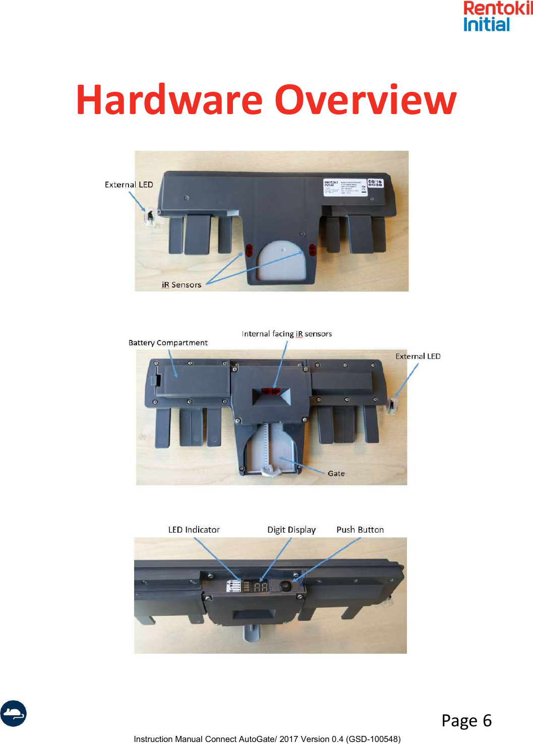
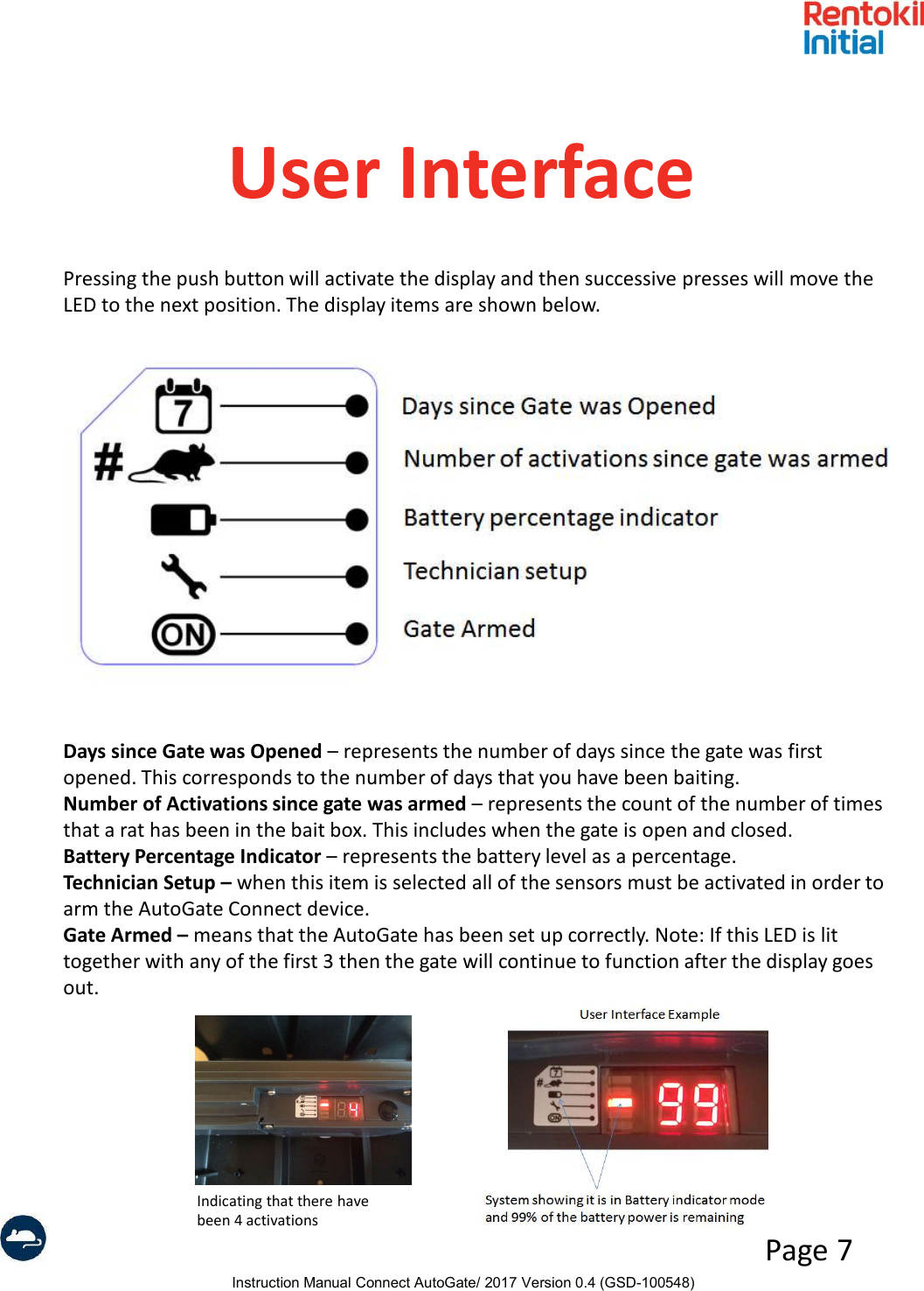
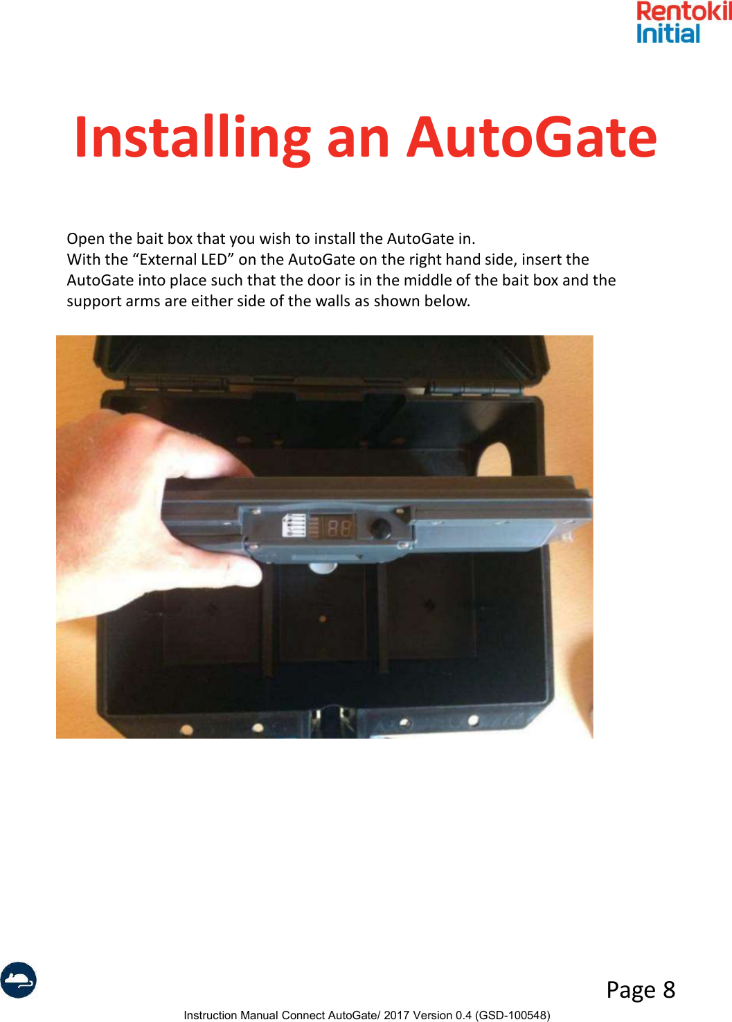
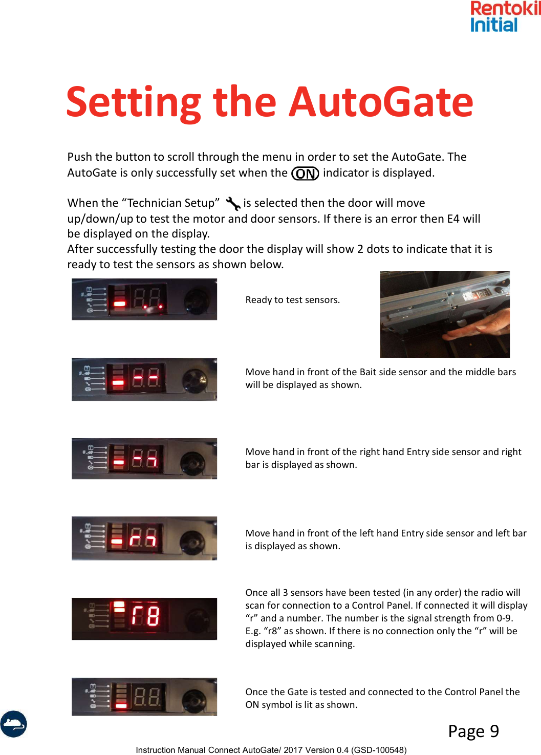
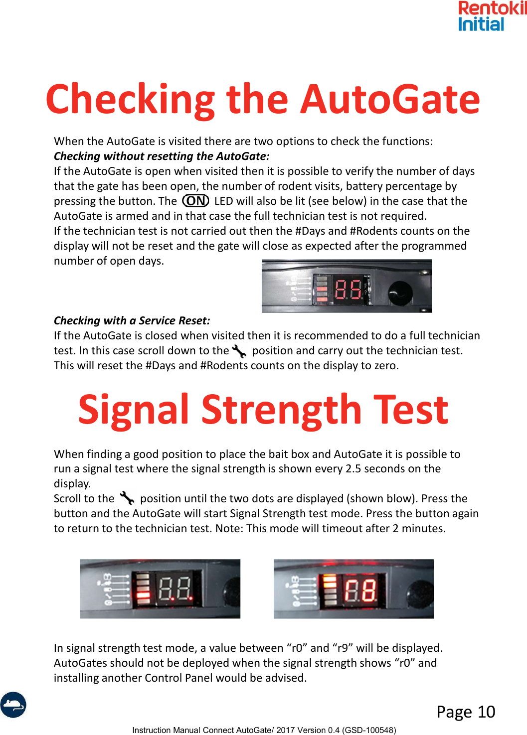
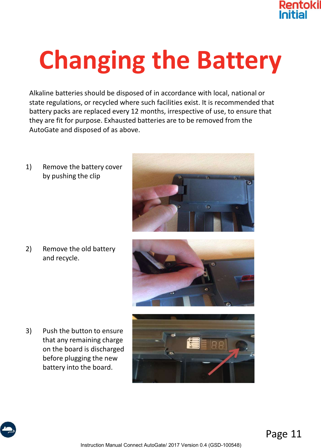
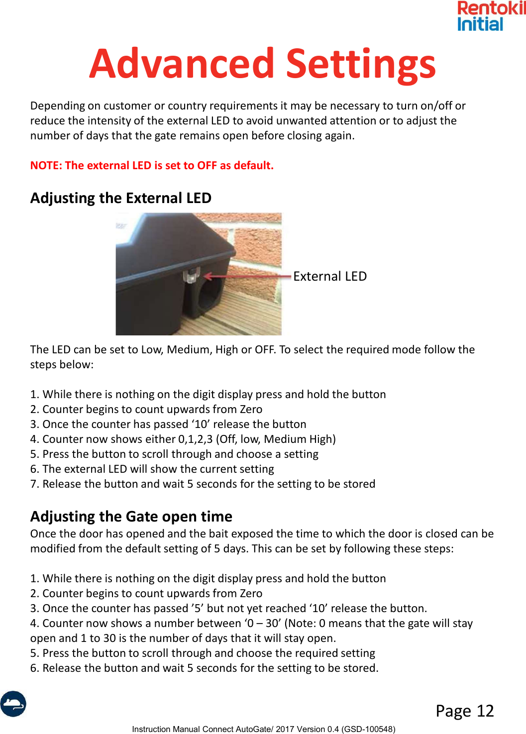
Users Manual - AutoGate Connect