Samsung Electronics Co HTZ320 DIGITAL HOME CINEMA SYSTEM User Manual 2
Samsung Electronics Co Ltd DIGITAL HOME CINEMA SYSTEM Users Manual 2
Contents
- 1. Users Manual 1
- 2. Users Manual 2
- 3. Users Manual 3
- 4. Users Manual 4
- 5. Users Manual 5
Users Manual 2
16
connections
CONNECTING THE SPEAKERS
Position of the DVD Player
Place it on a stand or cabinet shelf, or under the TV stand.
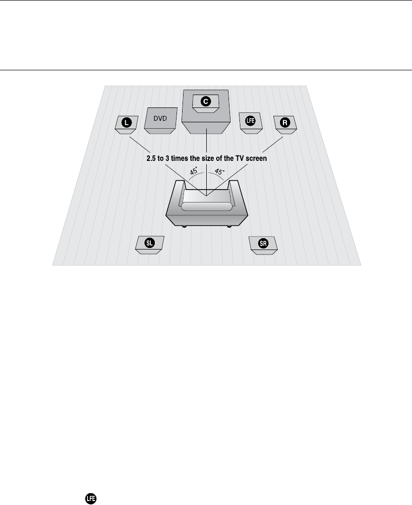
Selecting the Listening Position
The listening position should be located about 2.5 to 3 times the distance of the TV's screen size away from the TV.
Example : For 32" TVs 2~2.4m (6~8feet)
For 55" TVs 3.5~4m (11~13feet)
Front Speakers
ei
Place these speakers in front of your listening position, facing inwards (about 45°) toward you.
Place the speakers so that their tweeters will be at the same height as your ear.
Align the front face of the front speakers with the front face of the center speaker or place them slightly in front
of the center speakers.
Center Speaker
f
It is best to install it at the same height as the front speakers. You can also install it directly over or under the TV.
Rear Speakers
hj
Place these speakers behind your listening position. If there isn't enough room, place these speakers so they face each
other. Place them about 60 to 90cm (2 to 3feet) above your ear, facing slightly downward.
*
Unlike the front and center speakers, the rear speakers are used to handle mainly sound effects and sound will not
come from them all the time.
Subwoofer
The position of the subwoofer is not so critical. Place it anywhere you like.
This section involves various methods of connecting the Digital Home Cinema to other external components.
Before moving or installing the product, be sure to turn off the power and disconnect the power cord.
17
ENG ● CONNECTIONS● CONNECTIONS
Front/Rear & Center Speakers Cradle Stand and Wall Mount Installation
Front/Rear Speaker & Center Speaker
HT-Z320
Front Cradle Stand Type (Braket not included)
Rear Cradle Stand Type (Braket not included)
Center Cradle Stand Type (Braket not included)
HT-TZ322
Front Tallboy Stand Type
Rear Cradle Stand Type (Braket not included)
Center Cradle Stand Type (Braket not included)
HT-TZ325
Front Tallboy Stand Type
Rear Tallboy Stand Type
Center Cradle Stand Type (Braket not included)
HT-Z420
Front Cradle Stand Type or Wall Maunt Stand Type
Rear Cradle Stand Type or Wall Maunt Stand Type
Center Cradle Stand Type or Wall Maunt Stand Type
HT-TZ422
Front Tallboy Stand Type
Rear Cradle Stand Type or Wall Maunt Stand Type
Center Cradle Stand Type or Wall Maunt Stand Type
HT-TZ425
Front Tallboy Stand Type
Rear Tallboy Stand Type
Center Cradle Stand Type or Wall Maunt Stand Type
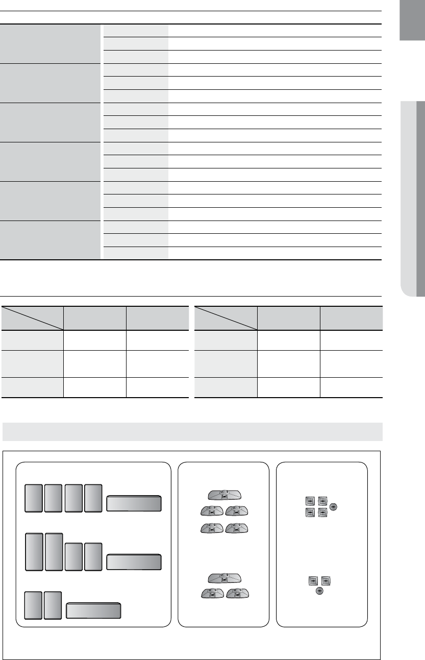
Speaker Components
CRADLE STAND/
WALL MOUNT
SPEAKER
HT-Z320
HT-TZ322
HT-Z420
HT-TZ322/TZ325
HOLE COVER
HT-Z320
HT-TZ322
HT-Z320 HT-Z420
SPEAKER 5EA 5EA
CRADLE STAND/
WALL MOUNT
—
5EA
HOLE COVER
—
5EA
Model
ITEM HT-TZ322 HT-TZ422
SPEAKER 3EA 3EA
CRADLE STAND/
WALL MOUNT
—
3EA
HOLE COVER
—
3EA
Model
ITEM
HT-Z320
18
connections
Front / Rear & Center Speakers Cradle Stand and Wall Mount Installation
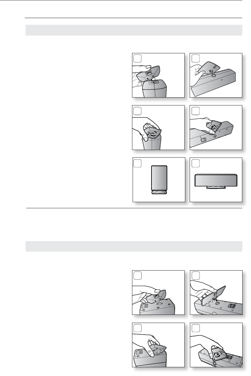
Installing the Wall Mount
<Front/Rear> <Center>
22
11
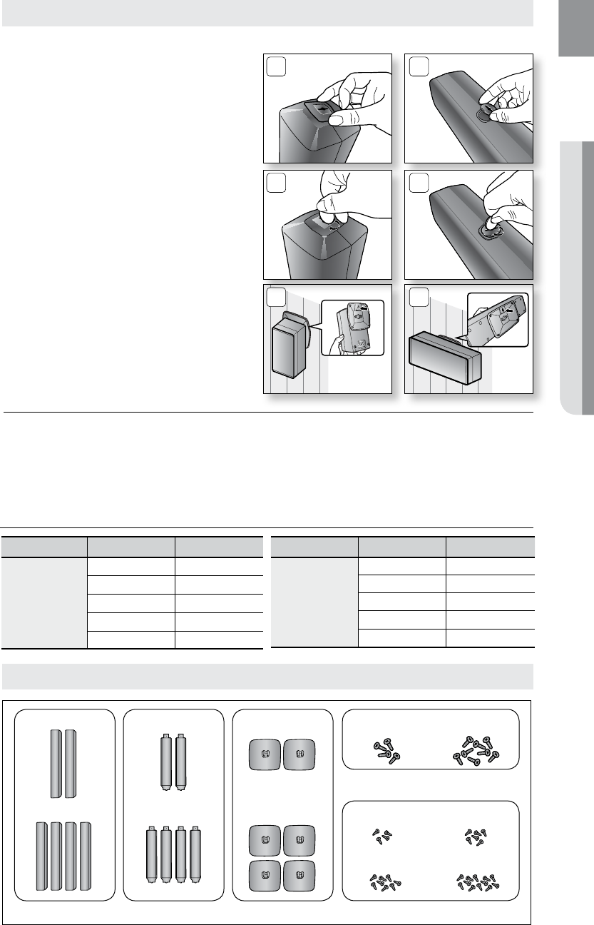
1. Insert the wall mount so that it fi ts into the
rear hole of the speaker as in the figure.
2. Turn the wall mount counter clockwise to
fix it. (This is the reverse direction to the
cradle stand.)
1. Insert the stand so that it fits into the hole
as described in the figure.
2. Turn the stand clockwise to lock it.
(Turning it counter-clockwise will
loosen from the hole.)
3. This is the completion of the stand
installation.
<Front/Rear> <Center>
M
The speaker system may vary, depending on the model. Please check your speaker system `
to see if i t includes the correct package of "Front/rear & Center Speakers"
corresponding to your model.
Installing the Cradle Stand
33
22
11
19
ENG ● CONNECTIONS● CONNECTIONS
Model Item Name Quantity
HT-TZ322/TZ422
SPEAKER 2EA
STAND 2EA
STAND BASE 2EA
SCREW (Large) 4EA
SCREW (Small) 4EA/6EA
Model Item Name Quantity
HT-TZ325/TZ425
SPEAKER 4EA
STAND 4EA
STAND BASE 4EA
SCREW (Large) 8EA
SCREW (Small) 8EA/12EA
Speaker Components
3. Put the hole cover on the hole of the
speaker.
4. Use a coin turn the hole cover clock wise to
fix it. (Turning it counter-clock wise will loosen
from the hole.)
5. Use the wall mount hole (bracket) to install
the speaker on the wall.
M
The speaker system may vary, depending on the model. Please check your speaker system to `
see if it includes the correct package of "Front/rear & Center Speakers"
corresponding to your model.
To avoid the speakers accident falling and consequently damaging yourself and the `
equipment, make sure the speaker is hung safely.
55
33
44
Front/Rear Tallboy Stand
<Front/Rear> <Center>
Installing the Wall Mount (Con't)
SPEAKER
HT-TZ322/TZ422
HT-TZ425/TZ425
HT-TZ322/TZ422
HT-TZ325/TZ425
STAND
HT-TZ322/TZ422
HT-TZ325/TZ425
STAND BASE SCREW (Small)
SCREW (Large)
HT-TZ322/TZ422 HT-TZ325/TZ425
HT-TZ322 HT-TZ422
HT-TZ325 HT-TZ425
20
connections
Front/Rear Tallboy Stand
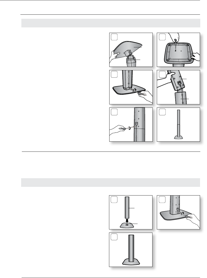
How to Install the Speaker on the Stand Base
Connect the1. SPEAKER with the
STAND BASE.
Insert the large 2. SCREW into the hole on the
rear of the speaker using a screwdriver as
shown in the illustration.
This is the3. SPEAKER successfully
assembled with the Stand Base.
1 2
3
SPEAKER
STAND
BASE
M
The speaker system may vary, depending on the model. Please check your speaker system to `
see if it includes the correct package of "Front/rear & Center Speakers"
corresponding to your model.
Turn the 1. STAND upside-down and connect
it to the STAND BASE.
Insert two small 2. SCREWS into the two holes
marked with arrows using a screwdriver as
shown in the illustration.
(HT-TZ325 : 2EA, HT-TZ425 : 3EA)
Insert a large 3. SCREW into the hole on the
rear of the Speaker STAND.
Connect the assembled stand to the 4.
SPEAKER.
Insert another large 5. SCREW into the hole on
the rear of the speaker using a screwdriver
as shown in the illustration.
This is the successfully assembled speaker. 6.
Make sure that the speaker is installed on a
flat and stable area. Otherwise it may be
easily knocked over.
1 2
3 4
5 6
How to Install the Speaker on the Stand
STAND
BASE
STAND
SPEAKER
STAND
M
The speaker system may vary, depending on the model. Please check your speaker system to `
see if it includes the correct package of "Front/rear & Center Speakers"
corresponding to your model.
21
ENG ● CONNECTIONS● CONNECTIONS
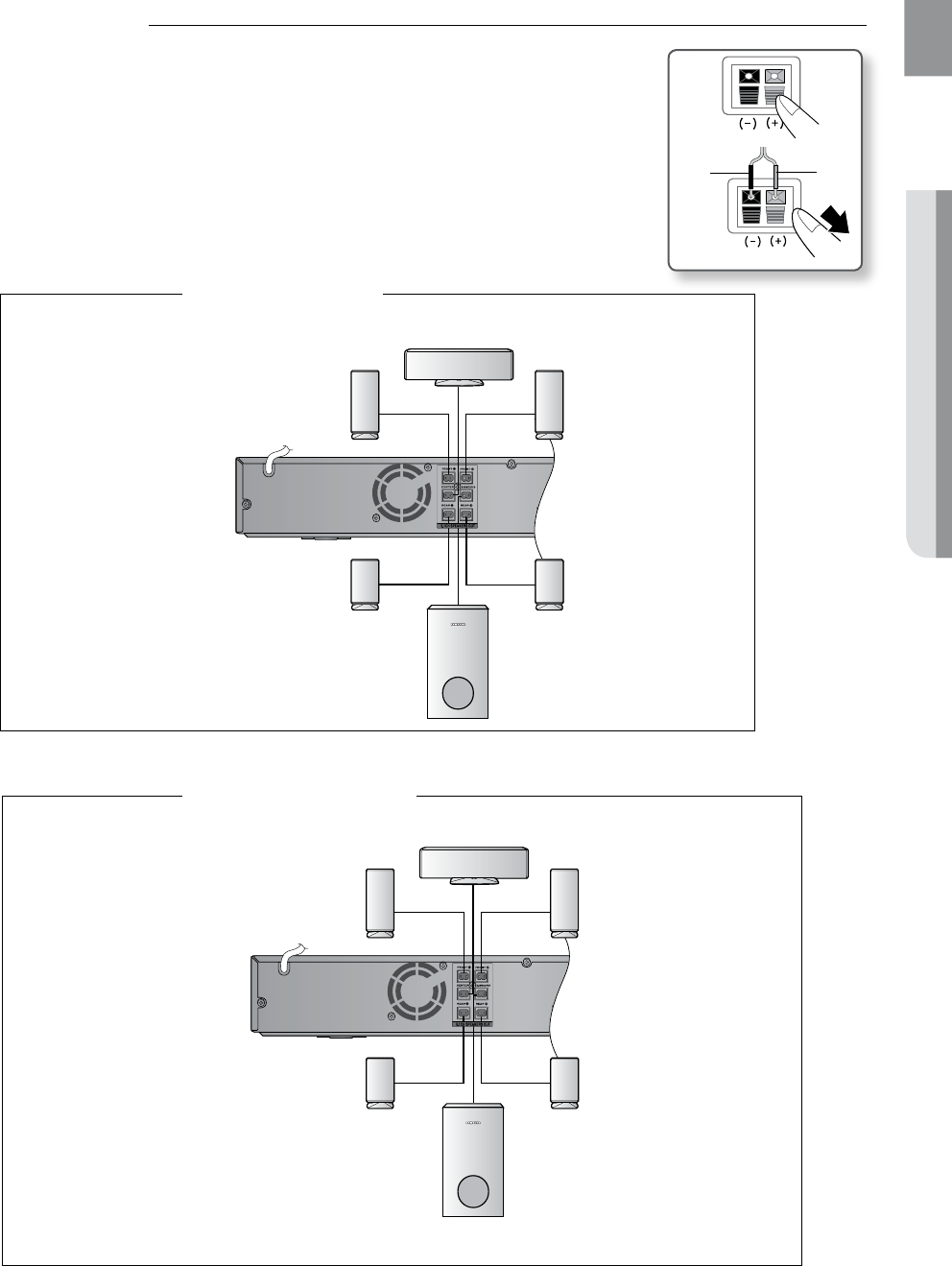
Connecting the Front, Rear, Center and Subwoofer Speakers
Press down the terminal tab on the back of the speaker. 1.
Insert the black wire into the black terminal (–) and the red wire 2.
into the red (+) terminal, and then release the tab.
Connect the connecting plugs to the back of the Home Cinema.3.
Make sure the colors of the speaker terminals match the colors •
of the connecting plugs.
Black Red
ipod
AUX IN 2
In case of HT-Z320
Front Speaker (R)
Center Speaker
Rear Speaker (R)
Front Speaker (L)
Rear Speaker (L)
Subwoofer
ipod
AUX IN 2
In case of HT-TZ322
Front Speaker (R)
Rear Speaker (R)
Front Speaker (L)
Rear Speaker (L)
Subwoofer
Center Speaker
22
connections
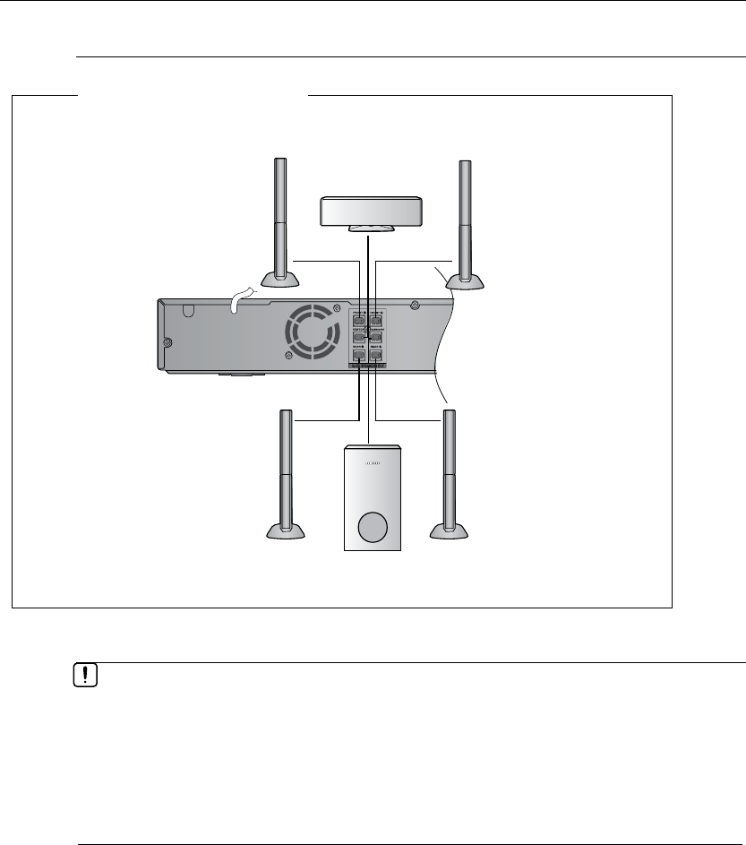
ipod
AUX IN 2
In case of HT-TZ325
Front Speaker (R)
Rear Speaker (R)
Front Speaker (L)
Rear Speaker (L)
Subwoofer
Connecting the Front, Rear, Center and Subwoofer Speakers
M
If you place a speaker near your TV set, screen color may be distorted because of the `
magnetic field generated by the speaker. If this occurs, place the speaker away from your
TV set.
Do not let children play with or near the speakers. They could get hurt if a speaker falls.
`
When connecting the speaker wires to the speakers, make sure that the polarity (+/ –) is `
correct.
Keep the subwoofer speaker out of reach of children so as to prevent children from
`
inserting their hands or alien substances into the duct (hole) of the subwoofer speaker.
Do not hang the subwoofer on
`a wall through the duct (hole).
Center Speaker
23
ENG ● CONNECTIONS● CONNECTIONS
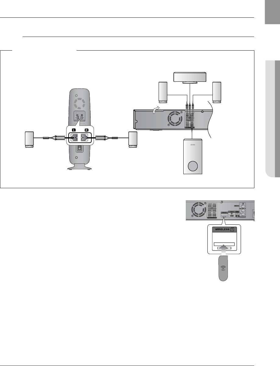
CONNECTING THE WIRELESS RECEIVING AMPLIFIER
(HT-Z420/TZ422/TZ425 ONLY)
Wireless Receiving Module (SWA-4100)
Connect the front, center and Subwoofer speakers to the 1.
DVD Player, referring to page 21~22.
With the DVD Player turned off, insert the TX card into the 2.
TX Card Connection (WIRELESS) on the back of the main unit.
Hold the TX card so that the slanted side faces to the left •
and insert the card into the port.
The TX card enables communication between the main •
unit and the wireless receiver.
Connect the left and right rear speakers to the wireless 3.
receiving module.
Plug the power cord of the wireless receiving module 4.
in the wall outlet
AUX IN 2
Slanted side face left
TX card
WIRELESS RECEIVER MODULE
ipod
RESET
Rear Speaker (L) Rear Speaker (R)
Subwoofer
Front Speaker (R) Front Speaker (L)
Center Speaker
In case of HT-Z420
M
HT-Z320/TZ322/TZ325 doesn't support wireless receivng function. `

24
connections
Do not insert any other card except the TX card dedicated to the product. `
If a different TX card is used, the product may be damaged or the card may not be
removed easily.
Do not insert the TX card upside down or in the reverse direction.
`
Insert the TX card when the DVD Player is turned off. Inserting the card when it is turned `
on may cause a problem.
If the TX Card is inserted and wireless receiving module setting is complete, sound is not
`
output from the Rear Speaker connectors on the main unit.
The wireless receiving antenna is built into the wireless receiver module. Keep the unit
`
away from water and moisture.
For optimal listening performance, make sure that the area around the wireless receiver
`
module location is clear of any obstructions.
If no sound is heard from the wireless rear speakers, switch the mode to DVD 5.1 `
channel or Dolby ProLogic II .
In 2-CH mode, no sound will be heard from the wireless rear speakers. `
M
Place the wireless receiver module at the rear of the listening position. If the wireless `
receiver module is too close to the main unit, some sound interruption may be heard due
to interference.
If you use a device such as a microwave oven, wireless LAN Card, Bluetooth equipment,
`
or any other device that uses the same frequency (5.8GHz) near the system, some sound
interruption may be heard due to interference.
The transmission distance from the main unit to the wireless receiving module is about 33
`
feet (10m), but may vary depending on your operating environment. If a steel-concrete wall
or metallic wall is between the main unit and the wireless receiver module, the system may
not operate at all, because the radio wave cannot penetrate metal.
This product(HT-Z420/TZ422/TZ425) is also compatible with the wireless receiver module
`
SWA-4000.
25
ENG ● CONNECTIONS● CONNECTIONS
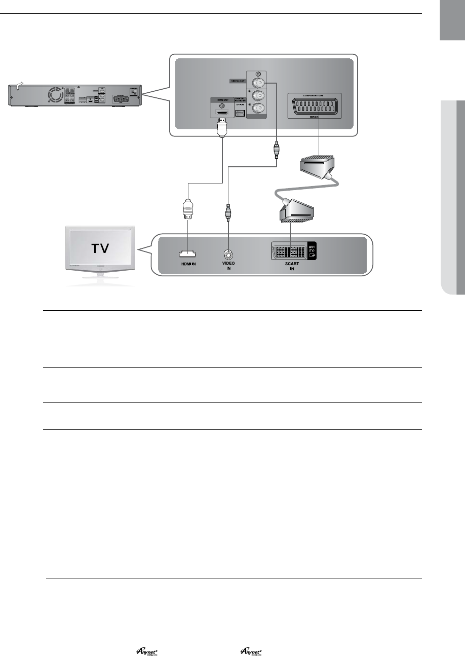
CONNECTING THE VIDEO OUT TO YOUR TV
Choose one of the three methods for connecting to a TV.
AUX IN 2
AUX IN 2
METHOD1 METHOD2
(supplied)
METHOD3
METHOD 1 : HDMI
Connect the HDMI cable (not supplied) from the HDMI OUT jack on the back of the DVD Player to the
HDMI IN jack on your TV.
METHOD 2 : Composite Video
Connect the supplied Video cable from the VIDEO OUT jack on the back of the DVD Player to the
VIDEO IN jack on your TV.
METHOD 3 : Scart
If your television is equipped with a SCART input, connect a SCART (not supplied) from the AV OUT jack
on the back panel of the main unit to the SCART IN jack on your television.
VIDEO SELECT Function
Press and hold the Number 0 (VIDEO SEL.) button on the remote control for over 5 seconds.
<COMPOSITE> or <RGB> will appear in the display. At this time, press the • Number 0 (VIDEO SEL.)
button shortly to select between <COMPOSITE> and <RGB>.
If Scart (RGB Input) is equipped for your TV, press the • Number 0 (VIDEO SEL.) button to select RGB
mode.
You can get a better picture quality by using Scart setting.
If Scart (RGB Input) is not equipped for your TV, press the• Number 0 (VIDEO SEL.) button to select
COMPOSITE mode.
M
Resolutions available for the HDMI output are 480p, 576p, 720p,1080i/1080p. `
This product operates in Interlace scan mode (576i, 480i) for component output. `
If you use an HDMI cable to connect a Samsung TV to the DVD Player, you can operate the Home `
Cinema using the TV's remote control. This is only available with SAMSUNG TVs that support
Anynet+(HDMI-CEC).
Please check the
`
logo (If your TV has an
logo, then it supports the Anynet+ function.)