Sepura SC2024 TETRA Terminal with Bluetooth User Manual SC202x User Guide
Sepura plc TETRA Terminal with Bluetooth SC202x User Guide
Sepura >
Contents
- 1. SC20_Series_Quick_Start_Guide
- 2. SC20_Series_UserGuide
- 3. Product_safety_guide
SC20_Series_UserGuide
User Guide
SC20 series hand-portable radio

Original Instructions: ENGLISH
Document Number: MOD-15-1895
Issue 1.0
Copyright
© Sepura plc. 2002–2016
All rights reserved. This document is intended for the use of Sepura plc’s customers and/or other parties only for the
purposes of the agreement or arrangement under which this document is submitted, and no part of it may be reproduced or
transmitted in any form or means without the prior written permission of Sepura plc.
Disclaimer
Sepura’s policy is to continually improve its products. The features and facilities described in this document were correct at
publication, but are subject to change without notice.
Software license agreement
NOTICE: CAREFULLY READ THE LEGAL AGREEMENT CORRESPONDING TO THE LICENSE YOU PURCHASED,
WHICH SETS FORTH THE GENERAL TERMS AND CONDITIONS FOR THE USE OF THE LICENSED SOFTWARE.
Contact Details
Sepura plc
9000 Cambridge Research Park
Beach Drive
Waterbeach
Cambridge
CB25 9TL
United Kingdom
sepura.com
ii SC20 series – 04/2016

CONTENTS
General information 1
Your radio at a glance 3
Battery 5
Charging the battery 7
Charging a 'flat' battery 8
Fitting the battery 8
Removing the battery 8
Using Sepura approved batteries 9
Controls & indicators 11
Navi-knob 11
Navigation Keys 11
Soft keys 13
Context keys 14
Status icons 15
LED indicators 19
Emergency button 19
Getting Started 20
Fitting a microSD card 20
Fitting a Smart card 21
Power on 23
Power off 23
Locking and unlocking the keypad 24
Home screen 26
Shortcut Bar 27
Notifications 27
Menu 28
SmartMenus 30
Help 31
Emergency operation 33
User Guide iii

Making an Alarm call 34
Receiving an Alarm call 35
Clearing an Alarm call 35
Power on Alarm call 35
Sound 37
Adjusting the volume 37
Loudspeaker on/off 37
Whisper mode 37
Audible tone alerts 38
Vibration alerts (Haptics) 39
Personalising your radio 40
Invert the display 40
Adjusting the backlight 40
Day/Night mode 41
Adjusting text and icon size 42
Setting the display language 43
Menu style 44
Time and Date 45
Talkgroups and folders 46
Typical folder arrangement 48
Select a talkgroup 49
Working with folders 50
Special folders 51
User Defined Scan Lists 52
Quick Groups 54
Contacts 55
Searching and filtering contacts 56
View contact details 57
Creating contacts 57
Editing contacts 58
iv SC20 series – 04/2016

Delete all contacts 59
Calls 60
Call types 60
Call History 61
Group calls 62
Individual calls 64
Broadcast calls 66
Missed events 67
Quick Calls 67
Smart Calls 68
Modifying your call setup 69
Text entry 71
Cursor movement 71
Character sets 72
Messages 74
Message Inbox 74
Opening messages 76
View message details 76
Reply to a message 77
Saved messages 77
Picture messages 82
Paging alerts 82
Networks 84
Authentication 84
Change Network 85
Transmit Inhibit 85
Fallback Mode 86
Operating Modes 87
DMO Mode 88
Repeater Mode 91
User Guide v

Callout alerts 95
Responding to Callouts 96
Callout display 101
Group calls to Callout group 102
Information Phase 103
Features 105
Privacy Screen 105
View images 105
Connector Protector 106
User profiles 107
Man Down 109
Lone Worker 112
WAP 113
Using WAP 113
Browser menu 114
Navigation menu 115
Settings 115
History menu 118
Using bookmarks 118
Call handling 120
GPS 122
GPS position 122
GPS direction 123
GPS reporting options 124
Bluetooth® 125
Bluetooth® on/off 125
Audio devices 126
Data devices 128
Modify connected devices 131
Security 132
vi SC20 series – 04/2016


viii SC20 series – 04/2016

General information
This user guide describes the default operation and features of the SC20 series
radio mobile radio. Your service provider or organisation may have
customised your radiomobile radioto optimise its performance to suit your
individual needs. There may be differences between this guide and the way
your product operates. Contact your service provider or organisation for
information about the customisation of your SC20 series radio mobile radio.
Safety Information
Before using this product read the safety and regulatory information
contained in the Product Safety Guide (SPR-DOC-00170) supplied with your
radio. It is your responsibility to ensure that this product is operated safely at
all times, and that local laws governing the use of Radio Frequency (RF)
devices are observed.
Sepura products are designed for use by mobile workforces, often working
alone, and are intended for use in occupational and controlled conditions. It
is recommended that you obtain training on how to operate this product.
Your personal safety could be at risk if you do not understand how to operate
this product correctly.
Sepura products have been tested to meet strict guidelines for personal safety
and operational conditions. Do not operate this product in environments that
exceed those listed on the product technical data sheet.
Waste Electrical and Electronic Equipment disposal information
This symbol on the product or its packaging indicates that this product must
not be disposed of as household or commercial waste. Some countries have
set up collection and recycling systems for waste electrical and electronic
products. By ensuring that this product is disposed of correctly, you will help
prevent potentially negative consequences for the environment and human
health, and help conserve natural resources. Please dispose of your waste
product according to your national and local regulations. Contact your
service provider or Sepura for information about disposing of this product in
your region of the world
User Guide 1
How to use this document
Icons and other visual cues are used throughout this document to help the
reader with important information. These icons and visual cues are described
below:
Warning:
Indicates that this information is important and if
disregarded could result in an injury to yourself or
to others.
Caution:
Indicates that this information is important and if
disregarded could result in serious damage to the
product or other devices or a minor injury.
Note:
Contains additional information that could be
exceptions to the general text. They may also
contain references to additional information in this
guide or other reading material.
Tip:
Contains additional information that could help you
perform a task quicker by offering an alternative
method to that in the general text.
Bold typeface Used to highlight parts of the radio, such as keys
and buttons, key presses and menu options.
Menu >Phone >
Contacts
Indicates navigation through the menu structure to
the desired option based on the default language
strings. Note: your radio may be customised to use
different language strings.
2SC20 series – 04/2016

Your radio at a glance
Item Description
1Antenna.
2Programmable Emergency Button. Press and hold (2 seconds) to initiate an
Alarm call.
3Rugged Accessory Connector (sRAC). Provides connection for accessories.
4Centre context key. Press to activate the feature or option that appears directly
above the key.
5Right context key. Press to activate the feature or option that appears directly
above the key.
6
Cancel/Home key. Press and hold (2 seconds) to power on your radio. From
the Home screen, press and hold (4 seconds) to power off. Press and hold (2
seconds) to return to the Home screen from any other screen.
User Guide 3

Item Description
7
Alphanumeric keypad with backlight. Loudspeaker and microphone behind.
The loudspeaker is used during Group calls when an audio acccessory is not
connected and the radio is held in the hand. The microphone is used during
phone calls. Use the keypad to enter alphanumeric characters for text editing
and dialling. Keys 0–9, # and * are programmable soft keys.
8Navigation keys. Press to scroll through lists and move the cursor when
writing text.
9Select/Send key. Press to initiate a phone call.
10 Left context key. Press to activate the feature or option that appears directly
above the key.
11 Colour display with backlight.
12
Earpiece and microphone. Earpiece is active during phone calls when the
radio is held like a smart phone against the ear. Speak into the microphone
during Group calls when the radio is not attached to an audio accessory and
held in the hand.
13 Tri-colour LED (indicator). Indicates various operational states of the radio.
14 Blue LED (indicator). Indicates a missed event such as a call, Callout or
message. Also indicates Bluetooth® status.
15 Navi-knob. A continuously rotating knob used to adjust the speaker volume.
16 Side Button (A/B). Press to activate a programmed feature.
17 PTT (Press-to-talk) button. Press and hold to talk during a group call. Release
to listen to other radio users.
18 Side Button (C). Press to activate a programmed feature.
19 Digital Accessory Connector (sDAC). Used to charge the battery, program
the radio and attach accessories.
20 Battery
21 Battery label area for attaching an asset label (optional).
22 Attachment point for accessory. Used to connect a belt clip or other accessory
designed for securing the radio during use.
23 External Antenna Connector used with a car kit to attach an external antenna
to the radio.
24 Radio ID Label for attaching an asset label (optional).
25 RFID tag for monitoring and auditing purposes.
4SC20 series – 04/2016
Battery
For your safety, inspect the battery regularly for any signs of damage,
such as cracks or surface damage caused by an impact or the battery
being dropped. Fit a new battery if there are any signs of damage.
Warning: Risk to personal safety. Sepura TETRA radios have been
tested and certified using Sepura approved batteries. The use of non-
approved batteries may damage the product, will result in non-
compliance with regulatory requirements, compromise the product
safety ratings including SARS, reduce the length of operating time and
will invalidate the product warranty.
Checking the battery charge
Always check the amount of battery charge before lengthy periods of
operation. A fully charged battery should provide continuous operation for a
full shift, depending on a number of operational factors such as how the
radio is operated, the operating environment (temperature and network
signal strength) and the condition of the battery. When the radio is powered
on, the amount of charge remaining may be displayed as a percentage (%) on
the screen.
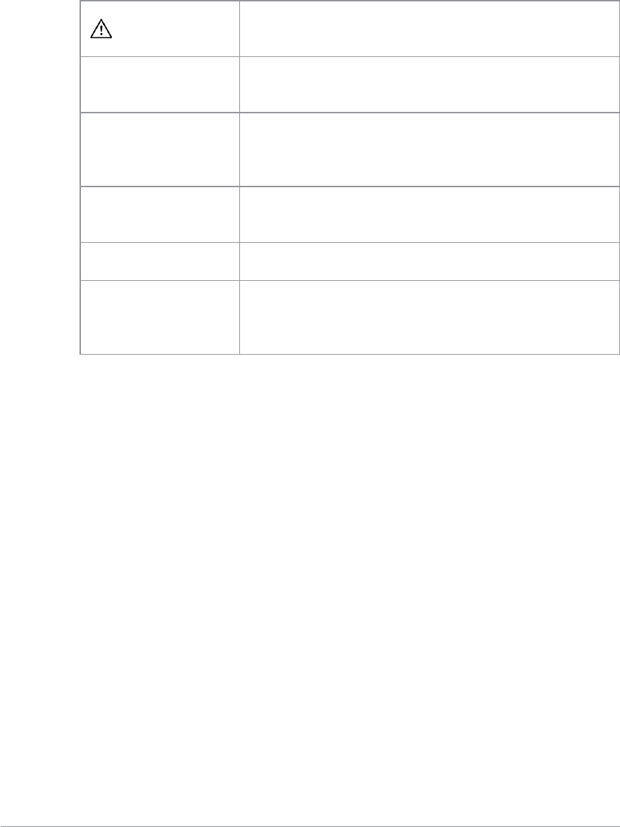
Battery charge indicators
Abattery meter appears on the status line at the top of the radio display. The
meter consists of 4 bars comprising 8 segments that fill and empty
corresponding to the estimated amount of charge remaining.
Icon Description
Battery is fully charged.
Battery is 50% charge capacity.
Battery has >12% charge remaining.
Battery charge less than 12% charge remaining.
User Guide 5

Optimising battery life
A fully charged battery should last a full shift (approximately 12 hours) but
this depends on a number of operational factors, such as how the radio is
operated, the operating environment (temperature and network signal
strength) and the condition of the battery.
Try the following to help you optimise battery life on a daily basis:
Ensure that batteries are fully charged at the start of a shift.
Decrease the amount of time the backlight stays lit between key presses
(see Adjusting the backlight on page 40).
Keep your speaker audio volume to a minimum (see Adjusting the volume
on page 37).
Reduce the length of time the radio is transmitting and keep DMOor
telephone type calls to a minimum because they cause higher current
consumption.
Shorten the GPS reporting intervals if enabled (see GPS reporting options on
page 124).
6SC20 series – 04/2016

Charging the battery
Your radio is powered by a rechargeable battery. The battery may be
recharged many times but it will eventually need replacing to ensure
continuous maximum performance from your radio.
First time battery charging
New batteries (Standard battery part no. 300-01174 and High Capacity battery
part no. 300-01175) are supplied in 'storage mode' which means they have a
minimum amount of charge for storage purposes. Before using a new battery
for the first time it must be fully charged to reactivate it. If the battery is used
before it is reactivated (fully charged) the radio may not power on, or may
indicate a low battery status icon or low level of charge.
Battery chargers
Only use Sepura approved battery chargers. Use of non-approved chargers
may not fully charge the battery or damage it. Always read the user
documentation supplied with the charger for additional safety instructions
and how to use it.
Charging methods
The radio may be powered on or off during charging.
Attach the Charger cable to the sDAC connector at the base of the radio or
place the radio with battery attached into a charging dock. If the battery is
charged attached to the radio, and the radio is powered on, an indication of
the remaining time to fully charge the battery is displayed (in hh:mm format).
During charging, the tri-coloured LED on the radio indicates the charging
progress and the charging icon appears on the status line, providing there is
sufficient charge in the battery to support this function.
Status LED Description
Flashing
Orange
Battery temperature is either too hot or cold to
commence charging.
Solid Orange Charging in progress.
Solid Green Charging complete.
Solid Red Battery has failed to charge and may be not be chargable.
Contact your service provider or Sepura.
User Guide 7
The battery may be charged separately from the radio using a battery-only
charger.
Charging a 'flat' battery
If the battery is completely 'flat' (without charge) during storage or after a
long period of non-activity, it may fail to recharge or stop charging after 20
minutes. If this happens, disconnect and then reconnect the charger (or
power off the charger, then power on) to reset the battery.
Avoid charging a flat battery attached to a radio. During charging, the radio
will attempt to power on when the battery charge reaches a certain capacity,
which will drain the battery of its charge.
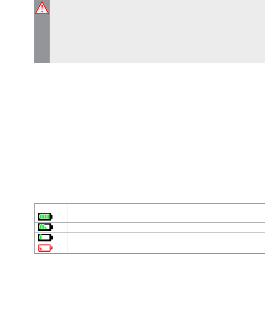
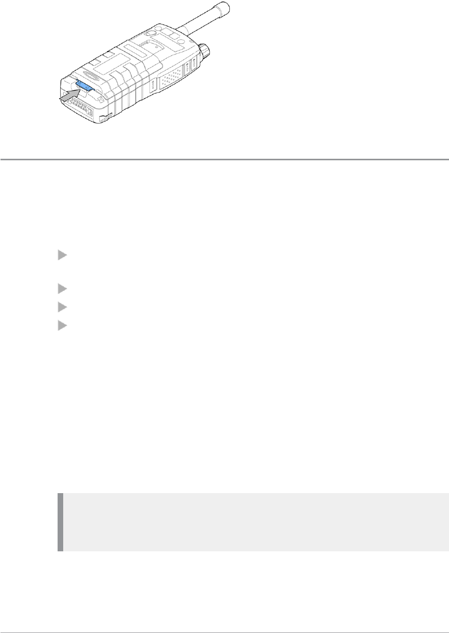
Fitting the battery
Ensure that the Smart/microSD card compartment cover is securely latched
before fitting the battery.
If a belt clip is fitted to the radio, lift the belt clip before attempting to fit the
battery. Do not attempt to insert the battery into the battery compartment
sideways under the belt clip. This may result in damage to the radio and the
belt clip.
To attach the battery, insert the battery into the battery compartment as
shown. Press the battery downwards until it clicks into position.
Removing the battery
Always power off before removing the battery.
8SC20 series – 04/2016
Push the safety latch on the bottom of the battery. Lift the battery upwards
and remove.
Using Sepura approved batteries
Your radio checks the authenticity of the battery when it is powered on and
has a number of battery management features that only work when a genuine
Sepura battery is fitted:
the remaining battery charge appears as a percentage when your radio is
powered on [customisable];
battery meter icons, showing the remaining battery charge;
a low battery warning appears when charge is low; and
you can check battery information, such as its authenticity, remaining
charge and serial number [customisable] (see Getting information about your
battery on the next page).
If your radio detects a non-approved battery, the message "Unidentified battery
-powering down" appears. The message is cleared by pressing any key.
If your radio detects a non-approved battery, the message "Unidentified
battery" appears.
If your radio detects a non-approved battery, the message "Unidentified battery
-powering down" and your radio powers off.
Caution: Non-approved batteries may not have inbuilt safety protection
features, and could potentially damage your radio (invalidating your
warranty) and affect your radio's safety and IP compliance ratings.
User Guide 9

Getting information about your battery
You can see information about the battery attached to your radio, such as the
remaining battery charge, whether the battery is authenticated (a genuine
Sepura battery) and the battery serial number [customisable].
Select Menu >Options >Battery Information.
The display shows:
Charge—the current remaining charge given as a percentage
Authenticated/Unauthenticated—a Sepura/non-Sepura battery is fitted
<serial number>—the serial number of the battery
Note: If a non-Sepura battery is fitted, the Charge is reported as 0%, the
battery is marked as Unauthenticated and the serial number is not shown.
10 SC20 series – 04/2016
Controls & indicators
Your radio has a number of controls and indicators.
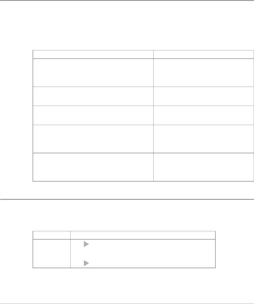
Navi-knob
The Navi-knob is a continuous rotating knob that in its normal mode is used
to adjust the volume. The Navi-knob can also be used to perform various
other functions.
To do this… Do this…
Adjust loud speaker volume (or
enable/disable Whisper Mode
[customisable])
Rotate Navi-knob
Move cursor and select characters (in
text entry mode)
Rotate Navi-knob in Text Entry
Mode or Editing Mode
Scroll through available talkgroups From the Home screen, press
Groups + rotate the Navi-knob
Scroll through available Status
Messages
From the Home screen, press
Groups 2 times + rotate the
Navi-knob
Scroll through available User Profiles
From the Home screen, press
Groups 3 times + rotate the
Navi-knob
Navigation Keys
Your radio has four navigation keys (left/right/up/down).
Key Action
Up/Down
Use to move the scroll bar up and down
to see more information
Scroll a list of options
User Guide 11

Down Open the top level menu from the Home
screen.
Up
Repeated presses moves upwards through the
options and menu levels until the top level
menu is reached.
Left/Right
Moves between options on the top level
menu.
Moves through the text characters for
selection when writing.
Tip: When the display is inverted (flipped upside down) the left and
right navigation keys work in opposite directions.
12 SC20 series – 04/2016
Soft keys
Some keys on your radio may be customised to provide one-touch access to
regularly used features. These programmable keys are referred to as soft keys.
To activate the soft key function:
assigned to a programmable soft key, press and release
assigned to other keys (such as the keypad, Cancel/Home and Select/Send
keys), press and hold for one second
The following keys can be customised as soft keys:
the Select/Send key
the Cancel/Home key
the Emergency Button (if not assigned to Emergency operation)
the programmable side buttons
all radio keypad keys (1–9,*,0,#,)
Note: During full-duplex PSTN/PBX calls, take care when trying to
activate soft keys (designated as 0–9,* and # keys) because they also
generate DTMF tones.
There are many functions that can assigned to a Soft key. Some functions are
activated immediately, such as the keypad lock/unlock or loudspeaker on/off.
There are some special functions that use a ‘navigate to screen’ function. This
means that on activation, a screen displays and you need to take some
additional action, such as activating a SmartMenu where you have to select
an option.
User Guide 13

Context keys
Your radiomobile radio has a left, centre and right context keys which you use
to select options displayed adjacent to them.
Context labels appear at the bottom of the screen, directly above each context
key. These labels show the action of the key when it is pressed; either
activating a feature or performing a function such as clearing a call (Clear) or
selecting an option (Select).
The labels and actions of the context keys in the Home screen are:
Context
key Label Action
Left Menu Press to enter the main menu.
Centre
Groups Press to change the talkgroup. See Select a
talkgroup on page 49
Status Press 2 times to send a status message. See
Send a Status message on page 1
Profiles Press 3 times to select a user profile. See User
profiles on page 107
Right Shortcut
Press to open the Shortcut Bar to quickly
access regularly used features or clear a
notification. See Notifications on page 27 and
Shortcut Bar on page 27
14 SC20 series – 04/2016
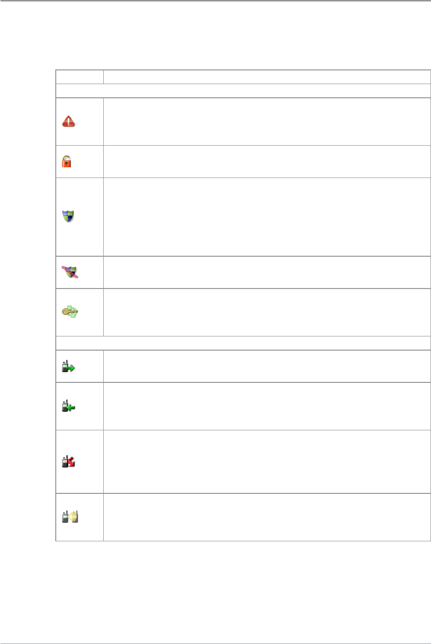
Status icons
Icons appear on the status line (at the top of the screen) when the radio is
engaged in certain activities or when certain functions are active.
Icon Description
Security and Emergency
Emergency
Appears when emergency operation mode is active on your
radio and an Alarm call is in progress.
Air Interface Encryption disabled
Calls and Callouts will not be encrypted.
E2E Encryption enabled
The Secure Communications icon indicates that the selected
talkgroup is customised for End-to-End Encryption. In other
words, calls you make by pressing the PTT button are End-to-
End Encrypted.
E2E Encryption disabled
Indicates that the call is not encrypted.
Key agreement
Briefly displays to indicate that a cryptographic key agreement is
in progress during power on and network connection.
Trunked Mode Operation (TMO)
Outgoing TMOcall in progress
You are in a call that you initiated.
Incoming TMO call in progress
You are in a call that was initiated by another person or your
dispatcher on the TMO network.
Missed incoming TMO call
The blue LEDflashes to notify you that you have missed an
incoming TMO call. A notification alerting you to the missed call
appears in the Shortcut Bar.
Scanning enabled
You radio is scanning (listening) to all available talkgroups within
your scan list for activity.
User Guide 15
Icon Description
Broadcast Call
A high-priority group call (point-to-multi-point) initiated by your
Dispatcher to all network radio users. You cannot reply to the
caller.
Direct Mode Operation (DMO)
Incoming DMO call
You are in a DMO call that was initiated by another radio user.
Outgoing DMO call in progress
You are in a call to another radio user.
Missed incoming DMO Call
The blue LEDflashes to notify you that you have missed an
incoming DMO call. A notification alerting you to the missed call
appears in the Shortcut Bar.
DMOGateway detected
Appears when the radio has detected a DMO gateway. The icon
disappears when the radio moves out of range of the gateway.
DMO Gateway off
DMO Repeater detected
Appears when a DMO repeater is detected and the radio can
communicate with any other radios in the selected DMO
talkgroup which are also in range of the repeater.
Repeater ignored
Repeater mode off
General icons
Signal Strength
Shows the current signal strength. More bars indicate a stronger
signal.
Good radio coverage
Indicates good radio coverage.
No service
Indicates poor signal or no radio coverage.
Battery Strength
Indicates the level of charge in your battery. More bars indicates
more charge.
16 SC20 series – 04/2016
Icon Description
Low battery warning
Appears when there is less than 12% charge remaining in the
battery.
Charging
Appears when the battery is attached to the radio during
charging and the radio is powered on.
Keypad locked
Transmit Inhibit
Indicates that you have activated transmit inhibit and the radio is
unable to transmit (overridden when Emergency mode is
activated).
Privacy mode active during a call
Appears for the duration of a call when Privacy mode has been
activated to prevent any other calls interrupting an important
individual call.
Covert operation mode enabled
The radio turns off any visual and sound alerts, and displays this
icon when covert operation mode is enabled.
Group Focus
Appears when Group Focus is enabled, preventing any calls
from other talkgroups (other than the selected talkgroup)
connecting to the radio.
User Profile
Appears when a user profile is activated. Your radio may be
programmed for a number of user profiles. The number next to
the icon indicates the chosen user profile.
Connector Protection enabled
Indicates that you have enabled connector protection. You can
use your radio is salt water environments without a cover fitted
to the Facilities connector at the bottom of the radio.
Connector Protection disabled
Indicates that connector protection is disabled. Do not use your
radio in salt water environments without a cover fitted to the
Facilities connector at the bottom of the radio.
User Guide 17
Icon Description
Communication Type Mismatch
This icon appears when there is a mismatch in communications
and is activated when:
the radio is out of range of a gateway when another radio
within range of the gateway is in a group call, and you
cannot participate in the call. and that you cannot take
part in the call.
a radio out of range of the gateway is attempting to
respond to a group call, and the speech if not being routed
using the gateway to TMO users.
a radio within range of a DMORepeater cannot make a call
and attempts to set up a call in DMO instead, the icon
appears on all radios within the talkgroup to indicate that
there are members of the talkgroup who cannot take part
in the call.
Bluetooth® device connected
Appears when you have activated Bluetooth® and have
successfully paired with a device.
Bluetooth® on, no device connected
Shows that you have activated Bluetooth® but do not have a
device connected.
Lone Worker protection enabled
Indicates that you have enabled the Lone Worker feature on
your radio.
Man Down motions and tilt sensors active
You have enabled the Man Down feature and the motion and tilt
sensors are active.
Man Down Tilt sensor active
You have enable the Man Down feature, but only the tilt sensor
is activated.
Man Down motion sensor active
You have enable the Man Down feature, but only the motion
sensor is activated.
GPS tracking enabled
Indicates that the GNSS (Global Navigation Satellite System)
function has been enabled.
GPS tracking not available
18 SC20 series – 04/2016
LED indicators
Blue LED
The blue LED indicates either a missed event, such as a missed call or unread
message, or your Bluetooth®status (if enabled). A notification alerting you to
the missed call, Callout or unread message appears in the Shortcut Bar. See
Notifications on page 27.
LED Indication Description
Flashing on for 1 second,
off for one second, on for
another second, then off for
seven seconds
Missed event
One flash every 10s Bluetooth®function is enabled
Continuous rapid flashing radio is in Bluetooth®discoverable (visible)
mode
Tri-colour LED
The tri-colour LED indicates the operational state of the radio.
LED Colour Description
Solid green Radio is powering on or in a call and receiving
Solid red Radio is in a call and transmitting
Intermittent
flashing red
Attempting to connect to the network or incoming
telephone SDS/Status message or battery low
warning
Flashing orange Incoming telephone call or SDS/Status message
Intermittent four
flashes orange Transmit Inhibit mode or Fallback mode are active
Emergency button
The red/orange button on your radio is typically programmed to activate an
Alarm Call. See Emergency operation on page 33.
Press and hold (2 seconds) the Emergency button to initiate an Alarm Call.
If the radio is powered off, press and hold (3 seconds) to power on and
initiate an Alarm Call. It may take several seconds for the radio to complete its
power on process before initiating the Alarm call.
User Guide 19
Getting Started
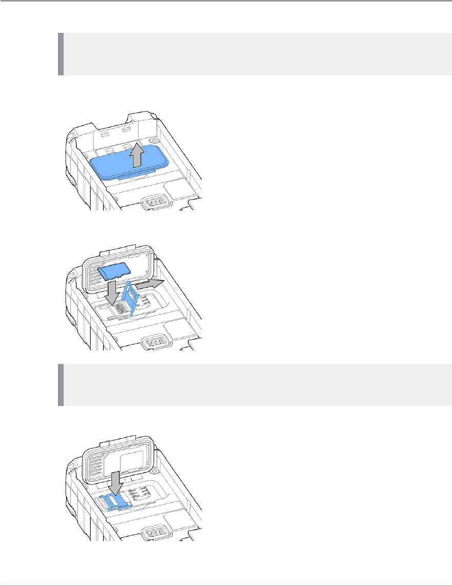
Fitting a microSD card
Note: Your radio supports microSDHC 32 GB cards that must be
formatted for the FAT16 file system.
1. Lift the cover using a small screw driver or tweezers.
2. Carefully lift the metal retainer and insert the card as shown.
Caution: Use care when opening/closing the metal card retainer. If it
becomes detached, it can be clipped back into place.
3. Carefully close the metal retainer.
20 SC20 series – 04/2016
4. Close the cover. Using your thumbs, press downward firmly on either side
of the cover as shown to secure each tab. You must ensure that the
compartment cover is secured. Not securing the cover will affect your
radio's IP rating.
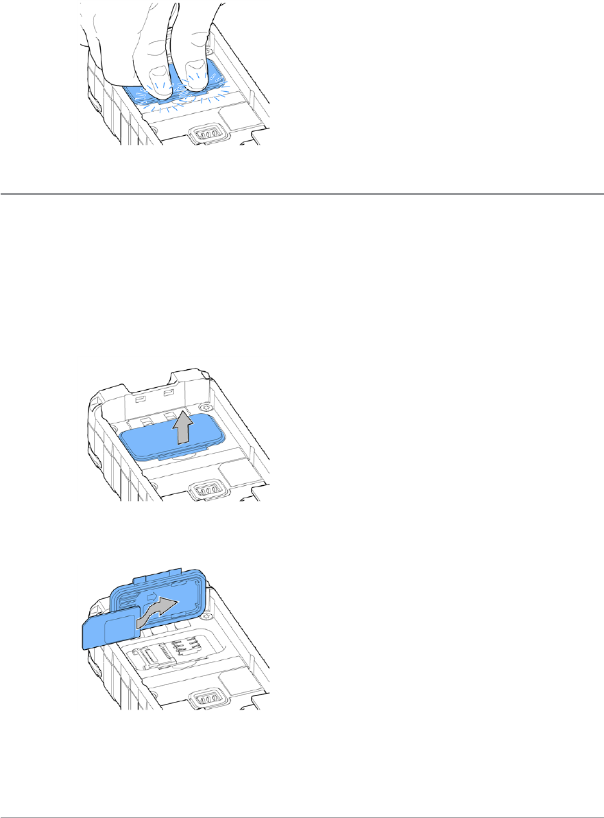
Fitting a Smart card
If required by your network operator, you may need to fit a Smart card to
your radio.
1. Lift the compartment cover using a small screw driver or tweezers. The
cover is secured by two tabs located at the top of the cover, either side of
the recess.
2. Insert the card into the slot on the underside of the cover as shown,
ensuring that the card is secured between the two tabs.
User Guide 21
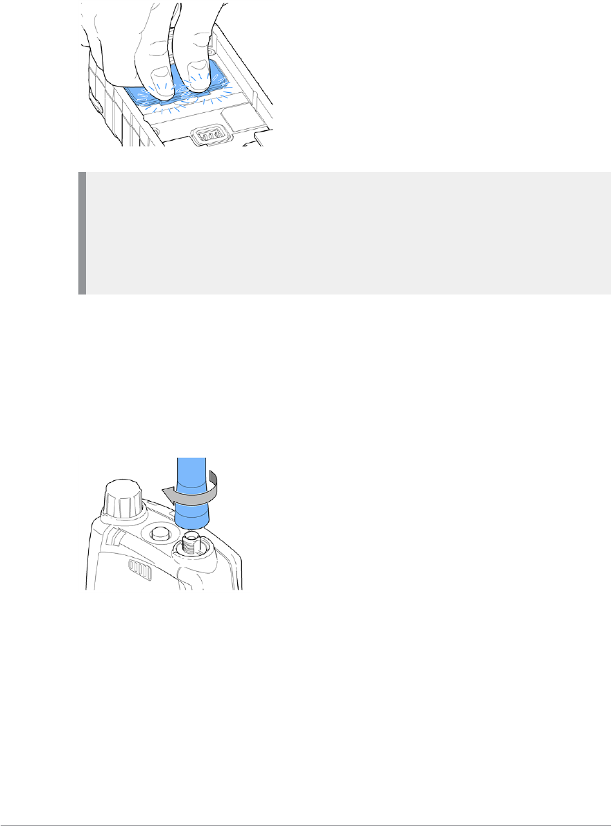
3. Close the cover. Using your thumbs, press downward firmly on either side
of the cover as shown to secure each tab. You must ensure that the
compartment cover is secured. Not securing the cover will affect your
radio's IP rating.
Antenna
Caution: Your radio must be fitted with an antenna at all times (unless
your radio is used with an external antenna such as an RSM) during
operational periods. Transmitting without an antenna attached my
damage the product. Your radio is designed for use with Sepura approved
antennas.
Always ensure that the seal between the antenna and the radio is maintained.
Never touch the antenna when the radio is transmitting. Ensure your radio
is powered off before fitting or removing the antenna.
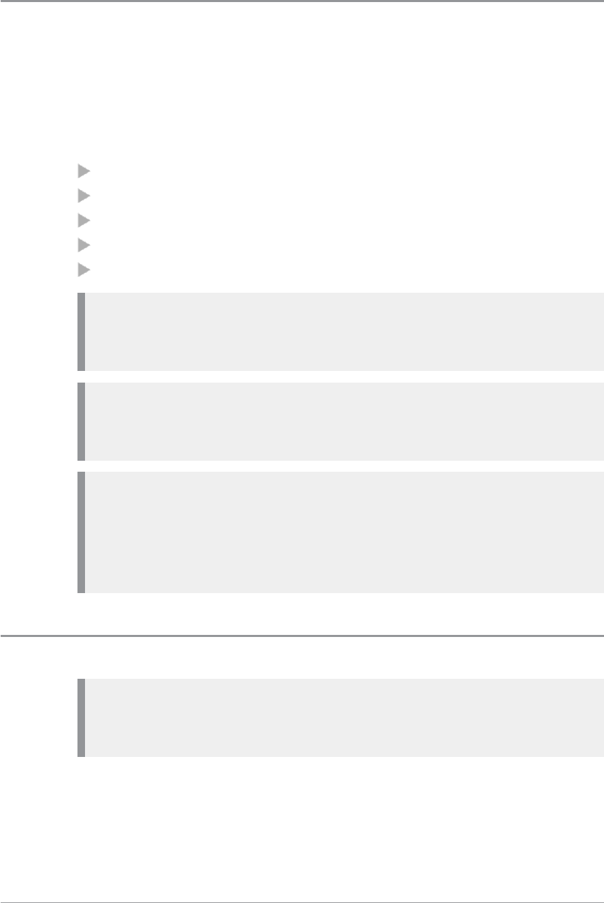
Fitting the antenna
1. Insert the base of the antenna into your radio's antenna connector.
2. Rotate the antenna clockwise until it is finger tight. Then apply another 1/4
turn clockwise.
Removing the antenna
Rotate the antenna counter-clockwise until it can be removed from the radio.
22 SC20 series – 04/2016
Power on
To power on, press and hold (2 seconds) the Cancel/Home key.
Your radio attaches to the last selected talkgroup when it was powered off (if
it is 'in service').
Depending on your radio's customisation any of the following may display:
the percentage of charge remaining, if a Sepura battery is fitted
a Sepura logo
a splash screen
a welcome screen
a PIN entry screen
Note: A message may be displayed relating to the authenticity of your
battery or attached accessory. A message may appear if your software
licence has or is about to expire.
Note: If your radio supports Radio User Assignment (RUA), which
authenticates your radio on the network, you may be prompted to log on
to your network. See Authentication on page 84.
Note: Transmitting in 3W RF is only available when using a Sepura 3W
battery. During power on the radio checks the authenticity of the battery
and whether it has the capacity for the radio to transmit 3W RF. A
message displays and the power may be limited if the radio cannot
transmit in 3W RF when licensed to do so.
Power off
Note: Do not power off the radio by removing the battery. The radio
must be powered off correctly to ensure that it performs a controlled
'powered down'.
To power off, from the Home screen press and hold (4 seconds) the
Cancel/Home key.
User Guide 23

Scroll to the Shutdown option, then press the Select key to power off your
radio. Before powering down, alerts and messages may be sent.
Note: If your radio is configured to provide an option to delete Callouts,
navigate to Shutdown or Delete Callouts then press the Select key.
Locking and unlocking the keypad
To prevent accidental activity during operation, you can lock the keypad.
This will also prevent access to the radio's functions if the radio is stolen.
When the keypad is locked, the Key icon appears in the status line.
The keypad can be locked manually or set to lock automatically after a period
of inactivity.
Note: If customised, your radio's keypad can be locked when an accessory
is attached.
Receiving calls with locked keypad
If you receive a telephone call when the keypad is locked your radio can be
customised so that the Select/Send key can still be pressed to answer it. If the
call is accepted the whole keypad is unlocked. Your radio can also be
customised so that you can press the Cancel/Home key to reject the call and
in this case the keypad remains locked.
Navi-knob with locked keypad
Your radio may be customised so that the Navi-knob is locked when the
keypad is locked. In this case you cannot alter the volume by rotating the
Navi-knob.
Your radio can also be customised so that the Navi-knob remains unlocked
and in this case it can be used for volume control only while the keypad is
locked.
To lock/unlock the keypad:
Press the *(star) key (or a designated soft key), then press the OK context
key to lock/unlock the keypad.
24 SC20 series – 04/2016

Tip: To quickly lock and unlock the keypad, press and hold (2 seconds)
the *(star) key.
If you press any other key while the keypad is locked no action is taken. The
Navi-knob remains unlocked when the keypad lock is enabled. A message is
displayed to remind you that the keypad is locked.
Alternatively, you can:
1. Select Menu > Options > Settings > Keypad Lock.
2. Press Lock to lock the keypad.
Setting the radio to automatically lock the keypad
You can set the radio to automatically lock the keypad after a period of
inactivity.
1. Select Menu > Options > Settings > Timed Keypad Lock.
2. Press Toggle to enable/disable auto keypad lock.
User Guide 25
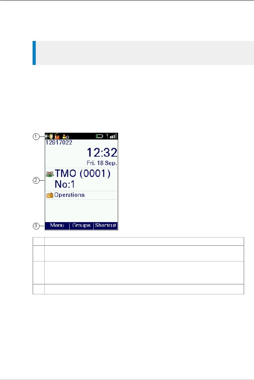
Home screen
The top level screen, known as the Home screen, appears when the radio
powers on and when it is idle.
Tip: To quickly get back to the Home Screen, press and hold (2 seconds)
the Cancel/Home key.
The status line, at the top of the screen, displays various icons to indicate the
state of operation or when certain functions like keypad lock have been
activated.
The context key labels at the bottom of the screen indicate what the context
key directly below the label is configured to do. These labels change
according to where you are in the menu hierarchy.
# Description
1Status line showing the radio coverage signal strength, battery
charge indicators, and operational status icons.
2
Information area containing information that only appears on the
Home screen. This is customised by your service provider or
organisation. It may show your selected talkgroup, date and time.
3Context key options (available in the Home screen).
26 SC20 series – 04/2016
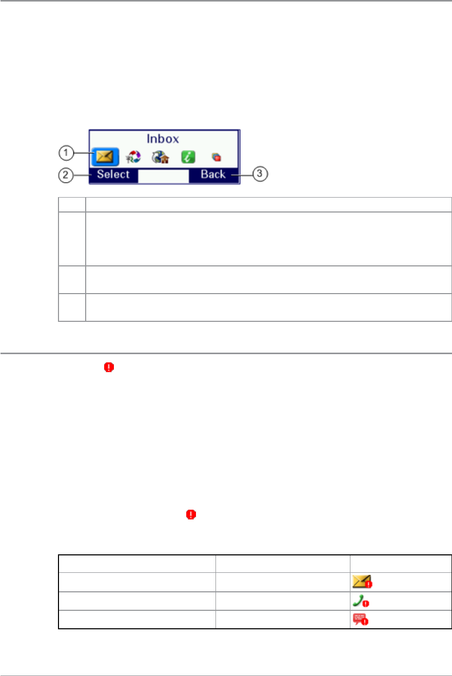
Shortcut Bar
You can easily access commonly used radio features such as your Inbox, and
turn features on and off using the Shortcut Bar. The Shortcut Bar can contain
up to 5 radio features and some of these can be paired with notifications to
alert you to a missed call or a new message in your Inbox.
To open the Shortcut Bar, in the Home screen press the Shortcut context key.
# Description
1
Use the navigation keys to scroll through the notifications and
features. Notifications always appear to the left of features. Press the
Right navigation key to continue scrolling right to view more
shortcuts (if available).
2To open a notification or feature, highlight it and press the Select
context key.
3Press the Back context key to close the Shortcut Bar without opening
a feature.
Notifications
Like a smart phone, your radio can display notifications to indicate a missed
call or new message. They also appear when certain functions are enabled
such as mute, transmit inhibit, and Lone Worker. Your radio can display up
to 5 notifications, and up to 5 shortcuts commonly used radio features.
Some features can be paired with notifications, such as your Inbox so when a
message is received a notification appears in the Shortcut Bar to alert you to
the unread message. When paired with a feature, the feature icon appears
with a notification badge .
The following notifications can be paired with a feature:
Notification Paired Feature Icon
Unread message Inbox
Missed call Call History
Missed Callout Callout
User Guide 27
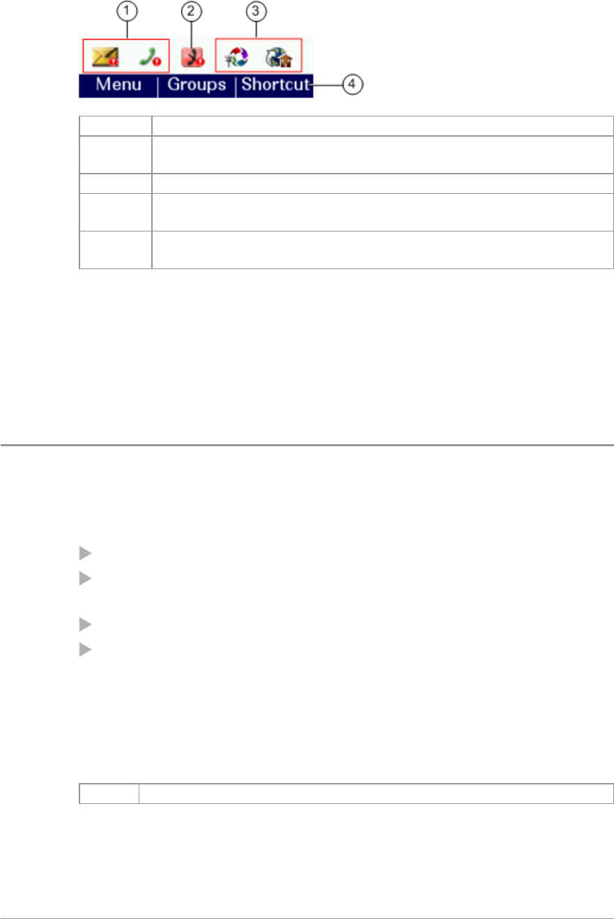
# Description
1Notifications paired with features appear to the left of all other
feature icons.
2 Example notification of a change of state (Transmit Inhibit).
3Shortcuts to commonly used features always appear to the right
of notifications. Scroll right to see more features (if any).
4In the Home screen, press the Shortcut context key to access the
notification.
To close a notification:
From the Home screen, press the Shortcut context key, highlight the
notification then press the Select context key. Use the feature in the usual
way, for example, read an unread message or respond to a missed call. The
notification automatically closes and disappears from the Shortcut Bar.
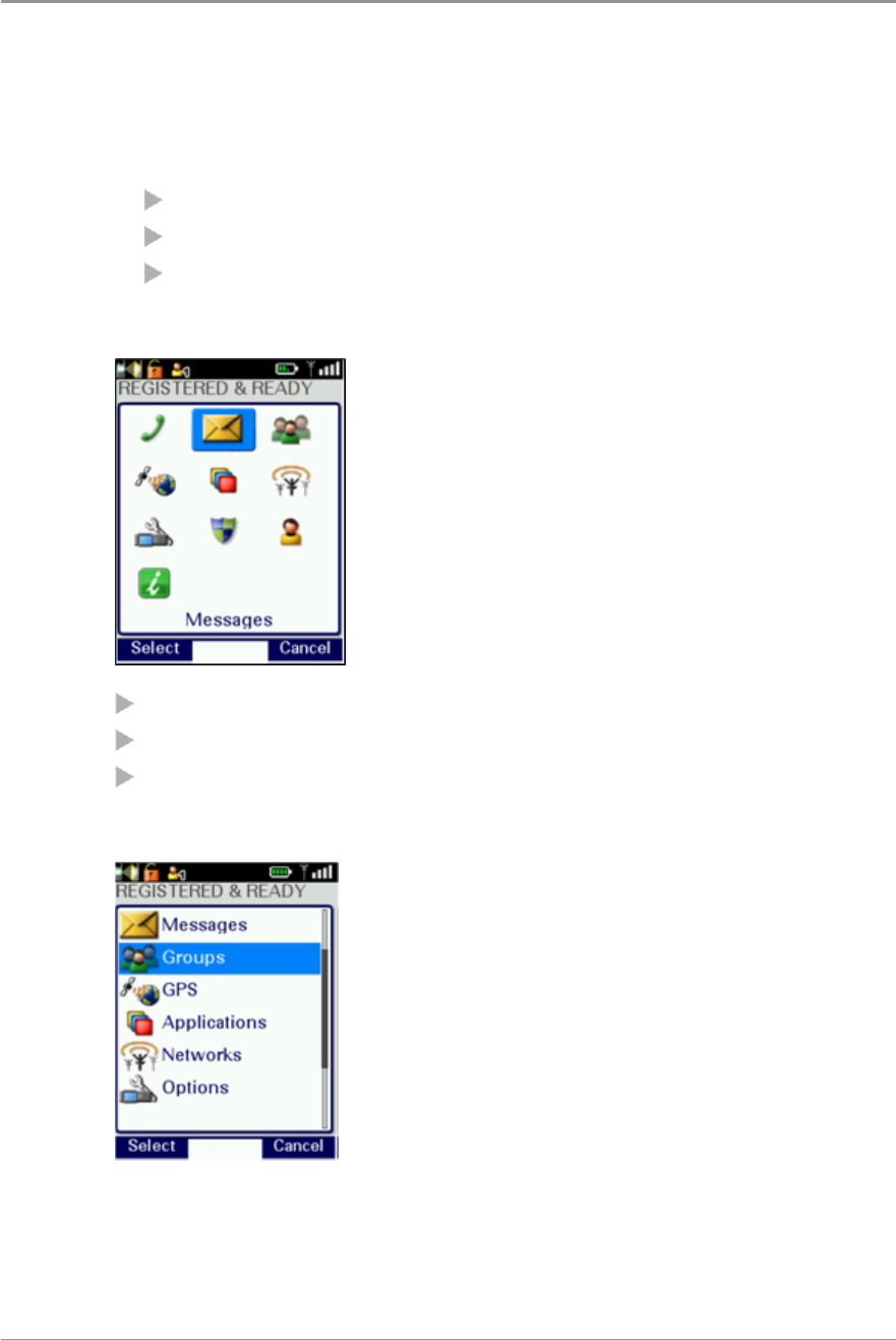
Menu
Your radio is customised by your service provider or organisation with a
number of features that are accessed from the main menu.
To open the main menu, in the Home screen press Menu.
To open a sub-menu or menu option, scroll to the option (highlight it) and
press Select.
To return to a higher level menu, press Back.
To return to the Home screen at any time within the menu hierarchy,
press and hold (2 seconds) the Cancel/Home key.
Menu options
The following icons are used to identify the sub-menus that provide access to
further options.
Icon Menu option
28 SC20 series – 04/2016
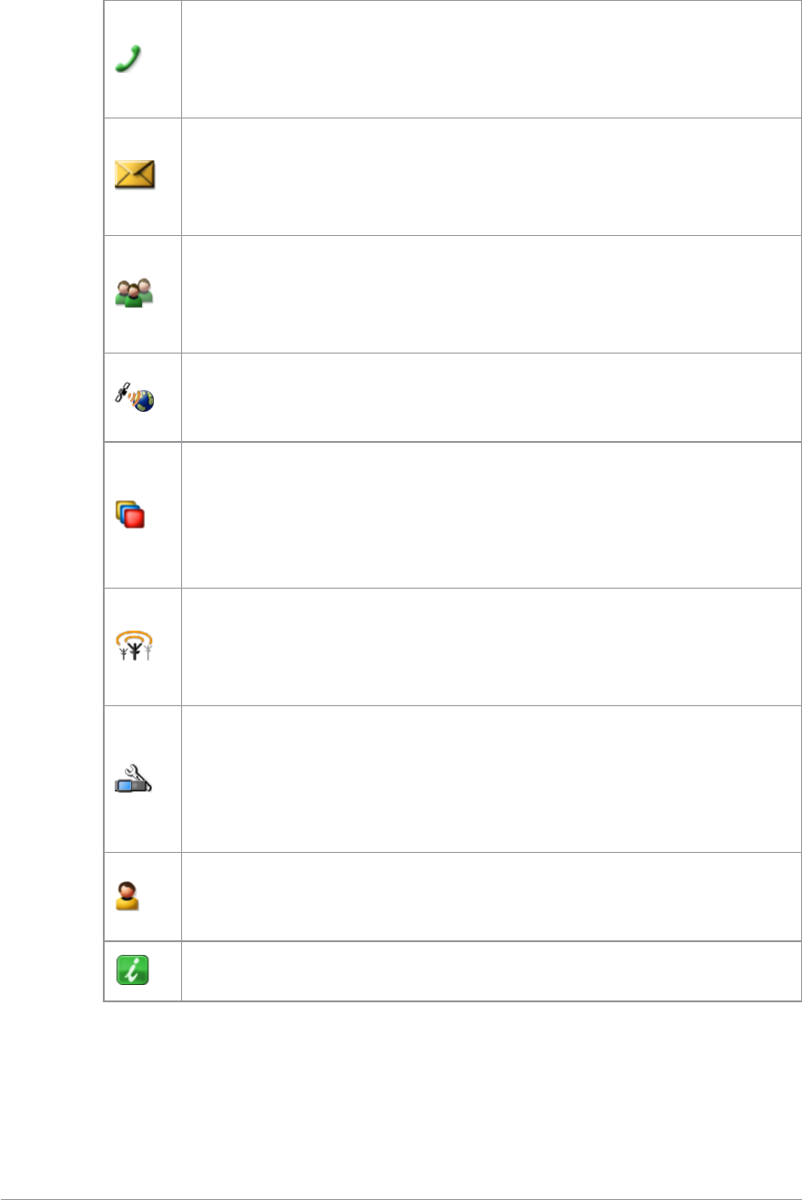
Phone
Add, edit and delete your personal contacts within your personal
folder. Search (or filter) your contacts to locate the contact you
want and initiate a call. Review you call history.
Messages
Read, create, save and send text (SDS) messages. View picture
messages (if customised). Select and send a status message. Clear
your mailbox of unwanted messages.
Groups
Search your talkgroup folders and select a talkgroup. Enable
scanning of your selected talkgroups. Set up your speech call
settings.
GPS
Manage your GPS location and position settings. View your
current location, direction and speed.
Applications
Your radio may be customised with a number of applications such
as Man-down and Lone Worker. Your service provider or
organisation may have installed specific applications (Short Data
Applications) to help you in your role. Access WAP sites.
Networks
Manage your network connections and DMO options. Change
your operating mode (TMO/DMO/Repeater). Enable/disable
Transmit Inhibit mode when working in RF sensitive areas.
Options
Manage your Bluetooth® devices and settings. Personalise your
radio settings such as backlight, text size and language. Enable
Connector Protector when working in salt laden environments to
protect your radio.
User Profiles
Select customised profiles designed specifically for the way you
work.
Help
View help, such as a list of customised soft keys on your radio.
User Guide 29
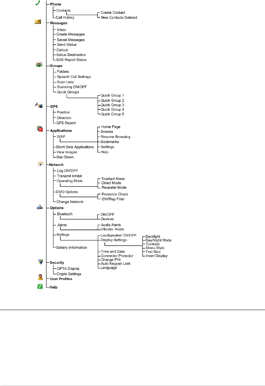
Menu Structure
SmartMenus
SmartMenus are designed to provide quick access to regularly used radio
features, usually with a common theme. Your service provider or
30 SC20 series – 04/2016
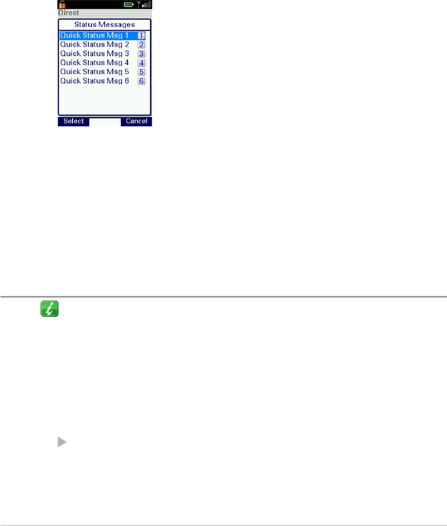
organisation may customise your radio with a number of SmartMenus, for
example you may have a SmartMenu containing all your Quick Status
messages, another for user profiles and another for selecting operational
modes such as toggling on/off covert mode, Transmit Inhibit, loudspeaker
mute and so on.
SmartMenus are assigned to a soft key, either a Side key or one of the keys on
the keypad. To open a SmartMenu, press the Side key or press and hold (1
second) the assigned key on the keypad.
Use the navigation keys to scroll the list of options on the SmartMenu.
Options are labelled with a number, shown to the right of the option. To
select the option, press the key that corresponds to the number of the option,
for example to select option 3, press the 3 key. Note that using this method
only options numbered 1 to 12 can be selected using the keys on the keypad
(press 0 for option 10, the Star (*) key for option 11 and the Hash (#) key for
option 12). For options numbered 13 onwards, scroll to the option (highlight
it), and press Select.
Help
The Help menu displays a free text area which is usually customised to
indicate radio soft key assignments. It may also be used to record any
required help text.
To access help
Use one of the following:
Press the Up navigation key (or Shortcut) to open the Shortcut Bar, then
select Help.
User Guide 31

Press a dedicated soft key (Sepura default is normally key ‘0’ zero).
Press Menu > Help.
32 SC20 series – 04/2016

Emergency operation
Emergency operation is available in TMO and DMO if the radio is in service.
If your radio is customised for Gateway and Repeater modes, it will make an
Alarm call in TMO. If it cannot make the call in TMO the radio will
automatically switch to DMO to make the call.
The red button on the top of your radio is programmed to initiate an Alarm
call at any time when your radio is in operation. This button is known as the
Emergency Button.
Your radio may be customised to perform one or more of the following:
Initiate an Alarm call set up to one or more pre-defined users (typically to
your dispatcher and other members of your talkgroup) and/or;
Send an Emergency Status message to an individual, the dispatcher or a
talkgroup and/or;
Send a position report (GPS dependent).
If you are working in RF sensitive areas and have enabled Transmit Inhibit,
prohibiting radio transmission, initiating an Alarm call will override the
Transmit Inhibit feature and the Alarm call will be transmitted.
Your service provider or organisation can provide information on how your
radio is customised for Alarm calls and how to operate your radio in
emergency situations. If you are working in a sensitive environment your
radio may be customised for Silent Alarm calls where audible and display
alerts are disabled, or your radio may be customised for Live Microphone that
allows you to call for assistance hands-free without pressing the PTT button.
Silent Alarm Call
If you are working in sensitive environments where the audible and display
alerts associated with an Alarm call are inappropriate, your radio can be
customised to make a Silent Alarm call (without acoustic or screen alerts).
Silent Alarm calls cannot be activated when operating in Lone Worker or
Man Down modes.
User Guide 33

When a Silent Alarm call is made, the radio displays the Home screen with
the talkgroup associated with call. During the call you may navigate away
from the Home screen.
Live Microphone feature
Your radio may be customised with the Live Microphone feature. This feature
allows you to broadcast a call for assistance hands-free for a specified period
of time and without having to press the PTT button. The radio automatically
cycles between transmit and receive communication during a programmed
period of time (seconds). Live Microphone is cancelled when the time expires
or by pressing the PTT button.
Making an Alarm call
You can still make an Alarm call if the keypad is locked.
To make an Alarm call
1. Press and hold (2 seconds) the Emergency button; a confirmation beep
sounds.
2. Release the button and speak into the microphone.
During an Alarm call:
the microphone is ‘live’ for a programmed period (seconds) allowing you
to speak hands-free without pressing the PTT button (customisable)
the LED illuminates solid red
your radio sounds audible tones
a large emergency symbol appears on the screen
your identity and talkgroup appears on the display of those receiving the
Alarm call
34 SC20 series – 04/2016
Receiving an Alarm call
An Alarm call overrides any existing calls on the talkgroup.
You know you are receiving an Alarm call when:
your radio sounds an audible tone
the LED flashes red
the emergency symbol appears on the screen
your radio status changes to Emergency
Clearing an Alarm call
You can only clear an Alarm call that you have initiated.
To cancel the Alarm call, press the Call Clear key, the Clear context key or
the Cancel/Home key. Alternatively, press and hold the Emergency button (2
seconds).
Warning: Depending on which network is being used, if the TETRA
Alarm call is a group call, then although both of the TETRA Alarm call
exit functions will clear the TETRA Alarm call on the call originator’s
radio, it will not remove the alarm from the system. It should also be
noted that those radios alerted to the emergency may, depending
upon the infrastructure configuration, remain in the TETRA Alarm call
condition until the dispatcher clears the call from the system.
When the Alarm call is cancelled, your radio returns to the talkgroup that
was selected before the call was initiated.
Power on Alarm call
If your radio is powered off, press and hold (3 seconds) the Emergency
button to power on and initiate an Alarm call. Any customised Welcome
screen is not displayed during power on. If your radio is customised for PIN
entry, you will need to enter your PIN before the alarm call is initiated. It may
take several seconds for the radio to complete its power on process before
initiating the Alarm call.
User Guide 35

Sound
Your radio is equipped with a loudspeaker for use during PTTcalls and a low
level speaker for use during telephone calls. You can adjust the volume of the
speaker and increase the sensitivity of the microphone (see Whisper mode
below) so that you can speak more quietly. Your radio also uses sound to alert
you to the various operational states.
Adjusting the volume
Rotate the Navi-knob to adjust the volume. A vertical volume meter displays
to indicates the current volume level. The radio sounds an audible tone at the
new volume level.
Loudspeaker on/off
Tip: A soft key may be customised to toggle the speaker on and off.
1. Select Menu >Options >Settings >Loudspeaker ON/OFF.
2. Press Toggle or press the Select/Send key.
Whisper mode
Whisper mode allows you to talk more quietly than normal but still be heard
and understood by the person you are calling. It can be useful to switch to
Whisper mode when providing confidential information.
Note: If you select a User Profile which already increases the sensitivity of
the microphone, depending on your radio's customisation Whisper mode
may not increase the sensitivity further.
To enable Whisper mode
Depending on customisation, to enable Whisper mode, you can:
User Guide 37
press a programmed soft key
rotate the Navi-knob to decrease the volume to below its lowest level
The radio sounds a low-high level alert when Whisper mode is enabled.
To disable Whisper mode:
Depending on customisation, to disable Whisper mode, you can:
press a programmed soft key
increase the volume until the volume level meter displays at least the
minimum level
increase the volume to its loudest level then attempt to increase the volume
further
The radio sounds a low-high level alert when Whisper mode is disabled.
Audible tone alerts
Certain events on your radio initiate audible tone alerts. These alerts are
attenuated when you select a user profile which uses covert mode (see User
profiles on page 107).
1. To toggle audible alerts
2. Select Menu >Options >Alerts > Audio Alerts.
3. Press Toggle (or the Select/Send key) to toggle alerts on/off.
Note: If your radio is turned off with Audio Alerts disabled they remain
disabled when the radio is next switched on.
38 SC20 series – 04/2016
Vibration alerts (Haptics)
Your radio can provide vibration alerts and haptic feedback to help you
recognise certain events, such as when a key is pressed, for example in a dark
environment, or when you are wearing gloves.
To toggle vibration alerts
1. Select Menu > Options > Alerts > Vibrator Alerts.
2. Select one or more of the following options:
Vibrator (Voice)—vibrate on incoming individual half-duplex or full-
duplex calls
Vibrator (Data)—vibrate on incoming SDS or Status messages
Vibrator (Alarm Key)—vibrate when Emergency Button is pressed
Vibrator (Key Press)—vibrate when any key (except Emergency Button
and PTT) is pressed
3. Press Toggle or the Send/Select key to enable/disable it as required.
4. To return to the Display Settings menu press Back or the Cancel/Home
key.
Tip: To stop the radio vibrating when a voice call is received, press a
Context key or the Select/Send or Cancel/Home key.
User Guide 39
Personalising your radio
You can personalise your display settings (such as text size, backlight,
inverting the screen and change languages) and create a personal phone book
containing your own contacts.
Invert the display
When you are wearing the radio on your shoulder, attached to a belt or to a
body vest, you may want to flip the display upside down to make it easier to
read. The Invert Display option rotates all screen elements (apart from the
Context key labels) by 180 degrees.
Tip: This feature is commonly assigned to a soft key or SmartMenu.
To invert the display:
1. Select Menu > Options > Settings > Display Settings > Invert Display.
2. Press the Toggle context key. When a tick appears in the check box, the
display is flipped, and when the check box is empty the display is set to
normal.
Note: When the display is inverted, the navigation keys work in opposite
to their normal function. Press the Up key to scroll down and the Down
key to scroll up. The Right key to scroll left and the Left key to scroll right.
Adjusting the backlight
When a call or message is received, and when you press any key, the
backlight lights up the display and keypad. The length of time the backlight
illuminates is set during customisation.
40 SC20 series – 04/2016
To adjust the backlight:
You can toggle the backlight on/off from the Shortcut Bar, by using a soft key
or from a SmartMenu (if customised).
Alternatively:
1. Select Menu >Options >Settings >Display Settings >Backlight.
2. Press the Toggle context key.
To adjust brightness:
1. Select Menu >Options >Settings >Display Settings >Day/Night Mode.
2. Select Backlight Level.
3. Rotate the Navi-knob to adjust the intensity of the backlight and the
keypad illumination on a scale of 1–7 (max.).
Day/Night mode
When a call or message is received, and when you press any key, the
backlight lights up the display and keypad. A bright display can be a potential
distraction, particularly when driving at night or in poor lighting conditions.
Day/Night mode lets you adjust the intensity of the backlight and keypad
illumination to suit your working conditions. Night mode reduces the glare
from the display, making it ideally suited for when the radio is cradled in a
vehicle at night time.
When the preferences for day and night mode have been set, switching
between the modes automatically adjusts the backlight and display settings.
To change Day/Night mode settings
1. Select Menu >Options >Settings >Display Settings >Day/Night Mode.
2. Scroll to each option (highlight it) to make your adjustments:
Day Mode—to toggle between Day Mode and Night Mode press the
Toggle context key.
Backlight Enabled—to toggle the backlight on/off press the Toggle
context key. When a tick appears in the box, the backlight is on, and
when the box is empty, the backlight is off.
Backlight Level—to adjust the intensity of the backlight and the key
pad illumination on a scale of 1 to 7 rotate the Navi-knob.
Tip: A soft key may be customised to switch between Day/Night mode.
User Guide 41

Adjusting text and icon size
Your radio uses the default size for the text and icons set during
customisation, however it also supports a number of different size modes that
control how text and icons are displayed. Having the ability to change the
text and icon size is useful when the handset is cradled in the car and you
want to enlarge the text and icons to make them easier to read from a
distance.
Caution: When selecting larger modes, some prompts or icons may not
appear on the radio display.
Your radio supports the following modes:
Normal Mode allows the maximum amount of information available to be
displayed in a compact character size.
Large Mode displays screen information in a large character size.
Very Large Mode displays the talkgroup number or talkgroup name, as
customised, in an extra large size on the Home screen with all other screens
in Large mode.
Custom displays the Home screen, menu and WAP browser in predefined
text sizes set during customisation. Only the Home screen supports Very
Large mode, with other screens set to either Normal or Large mode.
Note: Depending on the customisation of the Home screen, if the date is
shown on the Home screen it may be truncated in Very Large mode. If the
date format YYYY.MM.DD is used, then the day will not display.
To change text mode:
1. Select Menu >Options >Settings >Display Settings >Text Size.
2. Use the Up and Down Navigation keys to highlight the mode and then
press the Select context key.
The radio displays the Home screen, with the text and icons appearing in the
chosen mode.
42 SC20 series – 04/2016

Setting the display language
Your radio operates in the language chosen during customisation and can
support two display languages. The display uses the default language if the
radio is only customised for a single language, or the currently selected
language if two languages are programmed.
To change the language:
Tip: Your radio may be customised with a soft key or provide an option
on a SmartMenu to change the display language.
1. Select Menu >Options >Settings >Language.
2. Scroll to the language option, and then press the Select context key.
The Home screen appears and the display shows the selected language.
User Guide 43
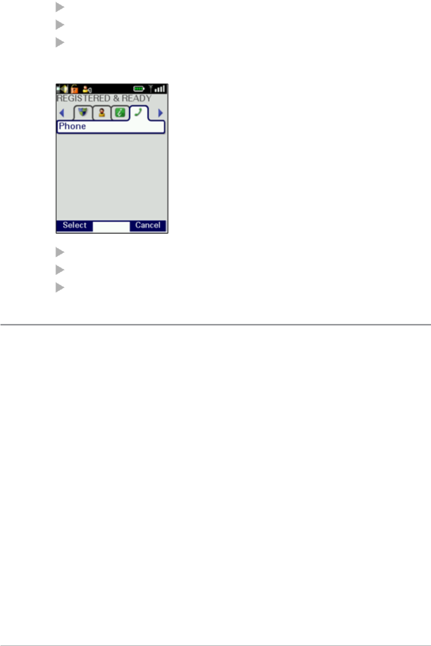
Menu style
You can display the menu in Grid,List or Compatibility style.
1. Select Menu > Options > Settings > Display Settings > Menu Style.
2. Select one option:
Grid—set Grid menu style
List—set List menu style
Card—set Card (Compatibility) menu style
Grid style
highlight items using the four navigation keys
to open an item press Select
to return to the top level screen press Cancel or Cancel/Home key.
List style
44 SC20 series – 04/2016
highlight items using the Down and Up navigation keys.
to open an item press Select
to return to the top level screen press Cancel or the Cancel/Home key.
Compatibility style (card)
highlight items using the Left and Right navigation keys
to open an item press Select
to return to the top level screen press Cancel or Cancel/Home key.
Time and Date
Your radio can be customised to display the current time and date on the
Home screen. The time is shown in 24 hour format. The day and month
appear in alphanumeric characters, for example Wednesday, 20 May. Your
radio may be customised to use shortened forms for the day (Wed.).
To view and edit the time and date
1. Select Menu >Options >Settings >Time and Date.
2. Press Edit or press the Select/Send key.
3. Enter the digits required (see Text entry on page 71).
4. Press OK or the Select/Send key to save your changes; press Cancel or the
Cancel/Home key to abandon your changes.
User Guide 45
Talkgroups and folders
Your radio can only participate in calls with talkgroups it is attached to via
the network. You can only initiate calls to other radio users in the selected
talkgroup. (However, when ongoing calls are detected on any talkgroup your
radio is scanning you can join in by pressing the PTT.) When your radio is
powered on it re-selects either the default talkgroup or to your last selected
talkgroup.
Talkgroups are pre-programmed onto your radio. Each talkgroup typically
contains users who have a similar role or who are within a distinct location or
who provide a service that you would use.
Talkgroups are organised into folders to help you quickly select one that is
applicable to your environment or situation. A top level folder can have a
number of sub-folders, similar to a folder structure on a computer. A folder
can contain both folders and talkgroups. The folders available depend on the
customisation of your radio; various ‘special’ folders are also programmed
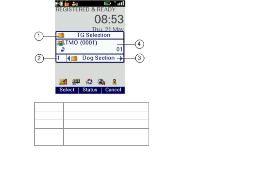
into your radio (see Special folders on page 51).
# Description
1 Header (customisable)
2 Folder level
3 Folder name
4 Talkgroup Information
46 SC20 series – 04/2016

Tip: Select the ‘All’ folder to select a talkgroup from a single list of all
talkgroups.
Note: Talkgroups in the Smart Call Folder-1 or Smart Call Folder-2 folders
can only be accessed when the appropriate Smart Call mode has been
selected from the Speech Call Settings screen or by using a soft key. (See
Smart Calls on page 68.)
User Guide 47
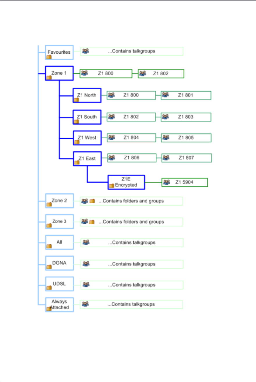
Typical folder arrangement
The following illustration shows how the folders can be used to organise
talkgroups:
48 SC20 series – 04/2016
Select a talkgroup
You can use one of the following methods to select a talkgroup:
From the Home screen, press the Groups context key.
From the Menu navigate to the Groups menu.
Use a soft key to return to your Home Group.
Centre context key (Groups)
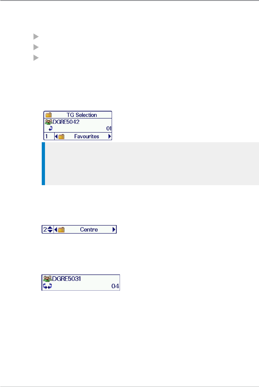
1. From the Home Screen, press the Groups context key. The current
selected folder and talkgroup appear in a selection box.
Tip: If you want to change to another talkgroup within the same
folder, simply enter the number of the talkgroup, or select the All
Folder which contains all the talkgroups and enter the number of the
talkgroup.
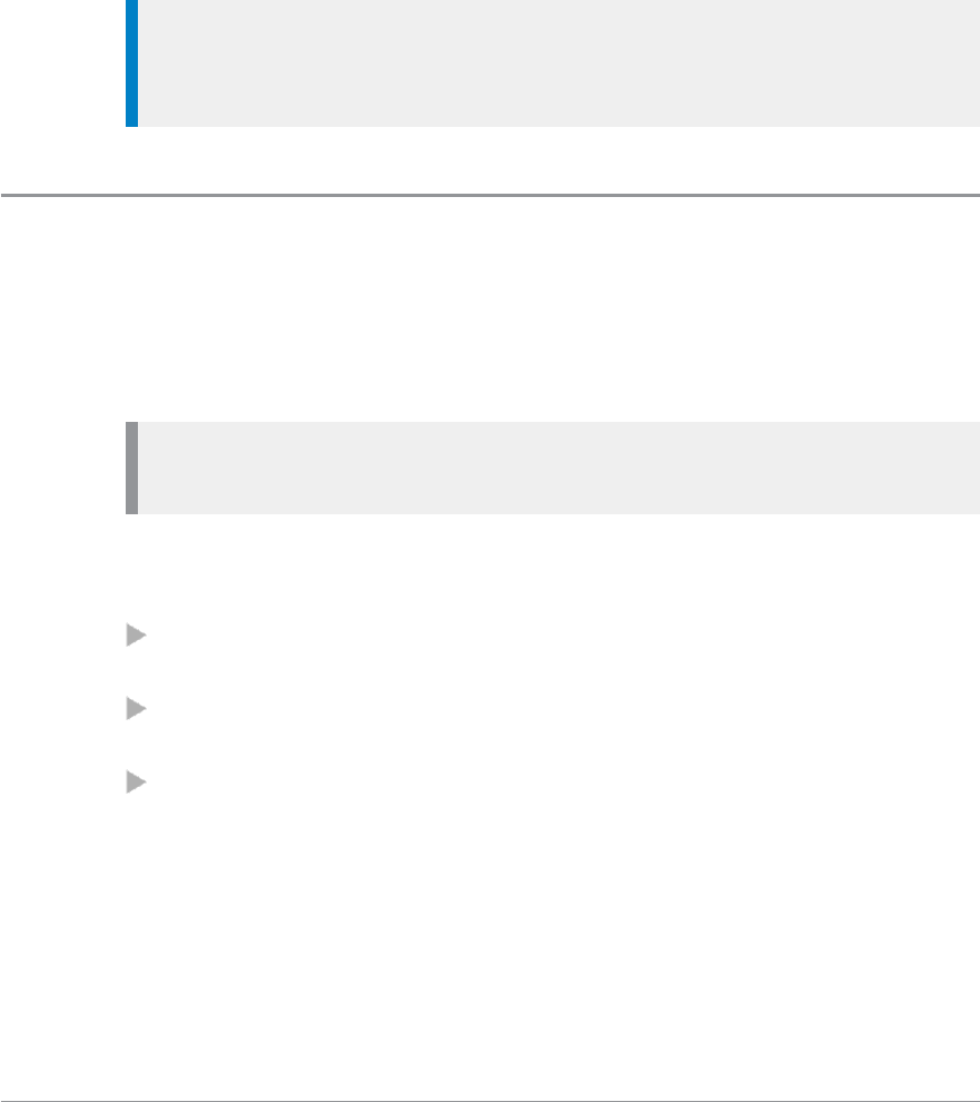
2. Use the Left and Right navigation keys to move between folders at the
same level. Use the Up and Down navigation keys to move between the
folder levels (sub-folders).
Rotate the Navi-knob to scroll through the talkgroups within the currently
selected folder. The directional arrows under the talkgroup name indicate
the rotational direction of the Navi-knob.
3. Press the Select context key to attach to the talkgroup.
User Guide 49

Working with folders
Various folder operations are available from the Folders menu:
Select Menu >Groups > Folders.
Opening a folder
1. Highlight a folder and press the Open context key.
Tip: To navigate back ‘up’ the folders list, press Back.
Searching for folders and talkgroups
You can search for talkgroups or folders by filtering on a text string. Items
which do not match the string are temporarily ‘filtered out’ of the list.
You can use either:
Search card—to filter the current talkgroup/folder folder.
Search all—to filter across all talkgroups and folders
1. To search inside a specific folder, open that folder.
2. Press Options then select Search card or Search all.
3. Enter characters you wish to filter against (see Text entry on page 71).
The list of matching names is dynamically filtered as characters are
entered. Only matching talkgroups or folders remain in the list.
4. To cancel the filter operation select the Stop search option.
Inserting a talkgroup into a folder
If a folder is editable you can use the Insert option to insert a talkgroup into
it.
Deleting a talkgroup from a folder
If a folder is editable you can use the Delete option to remove a talkgroup
from it. The talkgroup can still be selected from the All folder if customised,
or by entering the talkgroup number directly in the Talkgroup Selection box.
50 SC20 series – 04/2016
Create a ‘favourite’ talkgroup
To quickly access frequently used talkgroups, you can add them to the
Favourites folder.
1. Select Menu > Groups > Folders > Favourites.
2. Press Options, then select Open.
3. Navigate to the New Group option then press Options.
4. Press Insert.
5. Select the talkgroup you want to add (from any folder).
6. Press Select to insert the talkgroup into the Favourites folder.
Tip: If the New Group option is not available, you do not have 'edit'
permissions on the Favourites folder. The Favourites folder must be set to
'Edit' at customisation.
Special folders
In addition to the ‘standard’ folders created to contain your talkgroups, your
radio continuously scans talkgroups in ‘special’ folders for any activity
(except Favourites). When ongoing calls are detected you can join in by
pressing the PTT.
Note: Special folders can only contain talkgroups: they cannot contain
other folders.
The following special folders may be programmed into your radio during
customisation:
Background—talkgroups which the radio scans continuously for activity.
You cannot select a background talkgroup.
Always attached—talkgroups which the radio scans continuously for
activity. You can select a background talkgroup.
DGNA—contains up to 50 dynamically assigned groups. The contents are
automatically maintained by the radio and are not customisable. You can
select a DGNA talkgroup.
User Guide 51

UDSL—user-defined scan list(s), see User Defined Scan Lists below. A list of
talkgroups which you can modify yourself. If you select a UDSL instead of a
specific talkgroup your radio scans all the talkgroups in that UDSL. Until a
UDSL is selected its talkgroups are not scanned for activity. For more
information see User Defined Scan Lists below.
Favourites—frequently used talkgroups that can be added to the folder
during customisation or added by the user.
All—contains every talkgroup programmed into your radio. This includes
all talkgroups in the ‘standard’ folders created to contain your talkgroups
and those in all special folders (but not those in DGNA).
User Defined Scan Lists
A User Defined Scan List (UDSL) is a list of talkgroups which are either fixed,
or user-definable. Until a UDSL is selected the talkgroups it contains are not
scanned and your radio cannot receive calls from them. Your radio can have
a maximum of 20 UDSLs, and up to 10 talkgroups can reside within each
UDSL.
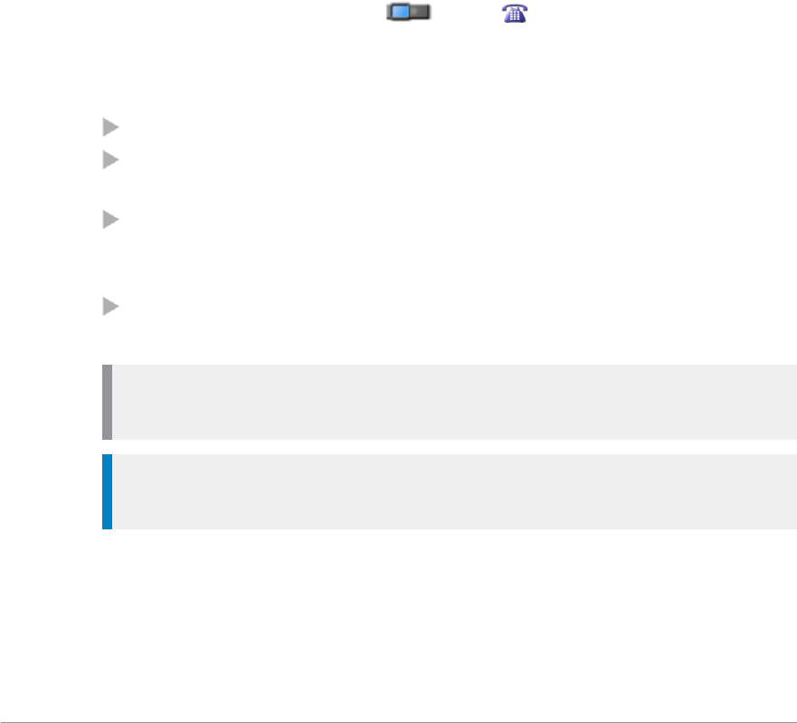
If you select a UDSL (in the same way as you select a talkgroup, see Select a
talkgroup on page 49):
the talkgroups it contains are scanned, allowing your radio to receive calls
from any of the talkgroups in the UDSL
the UDSL icon is displayed in the right hand corner of the radio
display
one talkgroup in the UDSL becomes the ‘selected talkgroup; when you
initiate calls they are made to this talkgroup (providing that there is no
activity on any other talkgroups being scanned).
Each talkgroup in a UDSL can have up to three different levels of user-
definable group scan priorities which are used by your radio when deciding
which call to follow when a call on one talkgroup is active and a call on
another talkgroup is received. The scan priority of each talkgroup in a UDSL
is shown at the right hand side of the screen as (High), (Normal) or
(Low). You can designate a selected talkgroup in each UDSL. You can add
and remove talkgroups from a UDSL.
52 SC20 series – 04/2016

View and edit scan list
1. Select Menu >Groups > Scan Lists.
2. Use the Up and Down navigation keys to select one of the UDSLs and
press Open.
3. Press Edit.
Change default (selected) talkgroup
1. Use the Up and Down navigation keys to select one of the talkgroups in
the UDSL.
2. Select Edit > Options > Select.
3. Select Edit > Options > Save.
Add a talkgroup
1. Press Options > Add.
2. The talkgroup selection box is activated. Select a talkgroup as described in
Select a talkgroup (described on page 49) then press Select.
3. Select Edit > Options > Save.
Remove a talkgroup
Select the talkgroup you wish to remove then:
1. Select Edit > Options > Delete.
2. Select Edit > Options > Save.
Changing group scanning priority
1. Select Edit > Options > Change Priority.
2. Select scan priority (High), (Normal) or (Low) then press Select.
3. Select Edit > Options > Save.
Scanning ON/OFF
You can enable or disable scanning of talkgroups in the selected UDSL. (Note:
the selected talkgroup is always scanned.)
1. Select Menu >Groups > Scanning ON/OFF.
2. Press Toggle (or the Select/Send key) to enable/disable scanning:
Scanning enabled—UDSL talkgroups are scanned. The Scanning icon
is displayed.
Scanning disabled—UDSL talkgroups are not scanned.
User Guide 53

Quick Groups
You can quickly change to a different talkgroup by pressing a customised
Quick Group soft key specified for that talkgroup.
To select the Quick Group talkgroup
Press the customised Quick Group soft key. Alternatively, view the
Quickgroup using the menu then press Select.
To view your Quick Groups
You can view the talkgroups and folders associated with your assigned Quick
Groups.
1. Select Menu > Groups > Quick Groups.
2. Use the Up and Down navigation keys to highlight a Quick Group then
press Select.
To change the talkgroup associated with a Quick Group
Your radio can be customised to allow you to change the talkgroup associated
with a Quick Group.
Note: These changes may be overwritten when your radio is
reprogrammed.
To associate to your current talkgroup
Select and view a Quick Group (described in To view your Quick Groups
above) then:
Select Options > Change > Current.
Your current talkgroup is now associated with the selected Quick Group.
54 SC20 series – 04/2016
Contacts
Details of regularly used contacts are stored in a phone book. The phone book
has a series of folders labelled Menu,Search,All and Personal. Your radio may
have additional folders containing contacts programmed into your radio
during customisation.
The Personal folder contains contacts you create (personal contacts). This
folder only appears when you create your first personal contact. The All
folder contains both personal contacts and contacts programmed into your
radio.
Each contact can have up to six associated numbers. A maximum of 6000
numbers can be held in the phone book. The icon next to each contact
indicates the dial mode, a radio or to a telephone, of the first
number associated with it.
Contacts are arranged in a series of up to 64 folders including the following:
All — contains all contacts in the Phone book
Menu — contains options to create and delete contacts in your Personal
folder
Search — allows you to search the entire Phone book for contacts and
numbers. Initially lists the names of all the folders in the phone book and
the number of contacts in each folder.
Personal — contains contacts you create. This is the only folder you can
edit.
Note: The Personal folder is hidden until you create your first personal
contact.
Tip: If customised you can also press the Shortcut context key in the
Home screen to open the Shortcut Bar, then select the Phone book.
To open the Phone book, from the Home screen, press the Menu context key,
then select Phone > Contacts.
User Guide 55
Searching and filtering contacts
You can search the entire phone book for contact names and numbers, or
filter the contacts within a folder by entering a search string into the Search
Bar at the top of any folder (except Menu):
When the search is complete:
the Search folder lists folders containing at least one entry containing the
search string, and the number of entries in those folders. You can open
any of the listed folders.
all other folders are filtered to show their matching entries above a dotted
line. All non-matching entries are listed below the dotted line.
Note: Spaces in a search string ‘split’ it into separate strings. Search
attempts to match each string in sequence.
To search for contacts and numbers within the phone book:
1. Select Menu > Phone > Contacts. Navigate to the Search folder.
2. Press the Up navigation key to open the Search Bar.
3. Enter a search string (see Text entry on page 71) and press the Search
context key.
4. When the search is complete, any folder containing a possible match to
your search (and the number of possible matches within that folder)
appear in the Search folder. To open a folder, select it and then press the
Open context key.
5. To clear the search string, press the Delete context key to delete each
character in the search string, then press the Cancel context key, then the
OK context key.
To filter contacts within a folder:
1. Open the folder.
2. Press the Up navigation key to open the Search Bar.
3. Enter a search string (see Text entry on page 71), then press the Filter
context key.
4. Any contact in the folder that is a possible match to your search criteria
appears at the top of the contact list. To view the contact's details, select
the contact and press the Open context key.
56 SC20 series – 04/2016
5. To clear the search string, press the Delete context key to delete each
character in the search string, then press the Cancel context key, then the
OK context key.
View contact details
1. Select Menu > Phone > Contacts.
2. Navigate to the contact you want to view details of then press the Open
key.
The contact numbers associated with the selected name are displayed. The
icon next to each number indicates its dial mode (for example, to a radio
or to a telephone).
To return to the original folder, press Cancel or the Cancel/Home key.
Creating contacts
Contacts you create are added to your Personal folder.
To create a contact:
1. Select Menu > Phone > Contacts.
2. Navigate to the Menu card and select Create Contact.
3. Enter the contact name (see Text entry on page 71) then press the Save
context key.
4. Select a dial mode for this contact, either TETRA Network (default) or
telephone/mobile network.
To change the dial mode, press the Up navigation key to select the dial
mode line then use the Left or Right navigation keys to switch dial modes.
Press the Down navigation key to continue entering the number.
Note: If the message Wrong number type appears, change the dial mode
or check that the length of the number is between 5 and 8 numbers.
5. Enter the number (see Text entry on page 71) then press the Save context
key.
User Guide 57

6. To add more phone numbers for the contact select Add Next Number and
repeat the previous step.
Tip: To add further contact numbers to a saved contact, open the
contact and select Add New Number at the end of its numbers list.
7. To return to the Personal folder press the Cancel context key or press the
Cancel/Home key.
Editing contacts
You can edit (and delete) contacts in the Personal folder of the Phone book.
To edit personal contacts:
1. Select Menu > Phone > Contacts and then select the Personal folder.
2. Navigate to the contact you want to edit, then press Open.
To edit the name:
1. Select the name and then press Edit.
2. Make changes as required, then press Save.
To edit a number:
1. Select the number and then press Options. Select Edit and press Select.
2. Make changes: to add additional digits press the number keys; to delete
digits press the Left navigation key.
3. After making changes press Save.
To delete a contact:
1. Select the contact and press Open.
2. Press Options.
3. Select Edit >Delete contact, then press Select.
58 SC20 series – 04/2016

Delete all contacts
You can delete all contacts in your Personal folder.
Tip: You can also delete individual contacts or numbers associated with
them, see Editing contacts on the previous page.
To delete all contacts
1. Select Menu > Phone > Contacts.
2. Navigate to the Menu card then select Delete User Contacts.
User Guide 59

Calls
The various types of voice and data calls that are supported by your radio,
and the acoustic and visual alerts that accompany a call, depend on your
radio's customisation.
Call types
Sepura radios support the following voice- and data call types:
Voice call types
Voice call type Description
Group
A call between you and a group of other radio users in
your attached talkgroup. A group call is always a half-
duplex call. Users can join and leave the call at any time.
Group calls are initiated by pressing the PTT button. See
Talkgroups and folders on page 46.
Individual
A call to another user or dispatcher in the TETRA
network, or to an external telephone subscriber via the
Gateway. full-duplex and half-duplex calls are
supported.
Individual calls to outside the TETRA network can be
made between a terminal or a dispatcher and a telephone
subscriber in a network to which the TETRA network
has a gateway interface. These calls are always full-
duplex.A full-duplex call is one in which both parties can
speak at the same time. The Select/Send and
Cancel\Home keys are used to initiate and end calls.
In a half-duplex call only one person can speak at a time
and needs to press the PTT button.
PBX
A call to a user on a private branch exchange (PBX). This
call needs to be set up by your service provider and
allows you to call a person by dialling their extension
number (preceded by a programmed digit used to dial
the exchange).
PSTN A call to a user on a the public switched telephone
network (PSTN).
60 SC20 series – 04/2016
Voice call type Description
Broadcast
A special type of group call, which is received by all
terminals in the system (system-wide broadcast call) or
by a specific group. The originator of a Broadcast call is
usually a dispatcher. The receiving members cannot talk.
Quick Call
A special individual call configured on a soft key to
request help or information from a pre-configured
individual or talkgroup destination in a non-emergency
situation. Quick calls can also send status and position
reports. They can have a call priority that is different
from the calls normally set up using the PTT or the
Select/Send key.
Smart Call
A special individual call made in Smart Call mode which
allows you to make group or broadcast calls to specific
talkgroups without the need to notify the network about
the talkgroup change. Smart Call mode is initiated from a
configured soft key.
Smart call priority can have a call priority value from 0
(undefined) to 15 (pre-emptive priority 4, emergency) in
TMO and to a value from 0 (undefined) to 3 (Emergency
pre-emptive priority call) in DMO.
Alarm Call
The Alarm Call has the highest call priority in TETRA.
Usually initiated by pressing the Emergency Button.
Alerts all other radio users on the talkgroup of the
emergency situation.
Data call types
Data call type Description
Individual full-duplex
Circuit Mode Data
Circuit Mode data calls have a very short transit delay
and so are suitable real-time services
Status Message
A Status message may have 65536 possible status values.
Of these, value 0 is defined to mean ‘Emergency,’ values
1–32767 are reserved, and values 32768–65535 are available
for network or user-specific definition.
SDS Message A user-defined message that can be sent by individuals
and received by individuals and talkgroups.
Packet Data
TETRA Packet Data extends TETRA to act as an IP
subnet. This enables application programmers to build
their applications in a well-standardised environment.
Call History
The Call History records up to 20 recent individual calls. It can be customised
to display Incoming Calls or Outgoing Calls or both sets of call types in a list.
User Guide 61
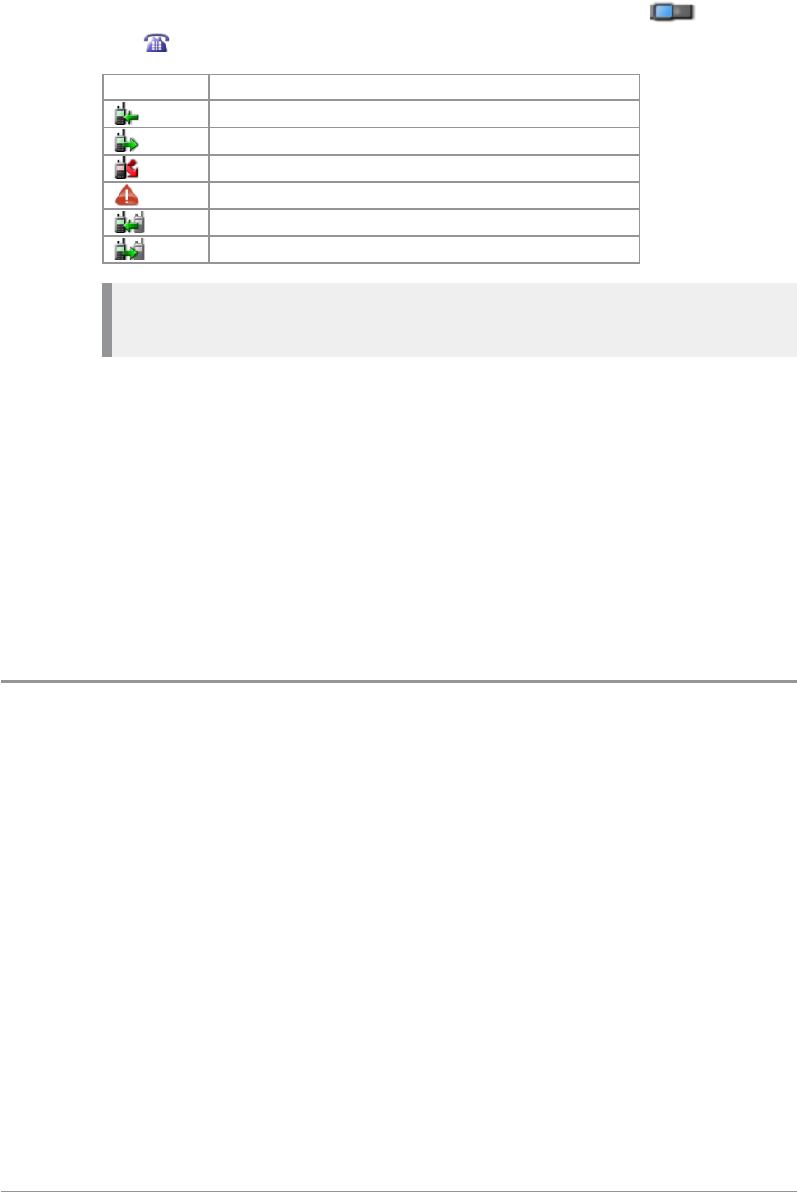
The following icons are used to distinguish different types of TETRA
and PBX/PSTN call events:
Icon Description
Received TMO call
Sent TMO call
Missed call. Call was not answered or cleared.
TETRA Alarm Call
Received TETRA DMO Call
Sent TETRA DMO Call
Caution: If you do not switch off your radio correctly (using the
Mode/Power key) the call history is deleted.
To display the call history
Select Menu > Phone > Call History.
To display the call information
Select a call in the call history list then press Open.
To make a call from call history
See Individual calls on page 64.
Group calls
Group (point-to-multipoint) calls are calls where you talk to other users within
a nominated group of radio users (a talkgroup). In a Group call only one
person can talk at any one time (known as half-duplex mode).
During Group calls the microphone at the top of your radio is active and all
received audio is routed to the loudspeaker.
Making a group call
1. Press and hold the PTT button and speak into the top microphone.
The LEDchanges to solid red to indicate that your radio is transmitting,
and an audible tone is heard and your radio status text changes to 'Talk'.
62 SC20 series – 04/2016

2. When you have finished talking, release the PTT button and listen to
audio received, through the loudspeaker.
The LED changes to solid green whilst the group call is active and your
radio status text changes to ‘Group Call’.
3. You can also clear the group call by pressing:
Clear Call soft key (if customised)
Cancel/Home key
Receiving a group call
When a Group call is received, the LEDflashes red and your radio status
changes to ‘Group Call’. The name of the talk group, talk group folder and
the caller’s ID are displayed. When the LED changes to solid green (after a
few seconds) you can respond to the call.
User Guide 63

Individual calls
Individual calls (point-to-point) are private calls between you and one other
person. You can make individual calls in two modes:
individual calls (half-duplex mode)—where only one person can talk at a
time using the PTT button.
individual ‘phone’ calls (full-duplex mode)—where both parties can talk
simultaneously. Use the Select/Send and Cancel/Home keys to initiate and
end the call.
During phone calls the bottom microphone (behind the keypad) and the
earpiece are active, allowing you to hold your radio against your head like
a telephone handset or a GSM telephone.
When an individual call is received, your radio sounds an audible alert and
displays the identity of the caller (if the contact is stored in your phone book)
or the ISSI of the caller.
Privacy mode
You can press a customised Privacy Mode soft key before dialling or during a
call to prevent interruptions from other calls during important or sensitive
call. When you have Privacy Mode enabled, calls made to your radio are
marked as missed calls (see Call History on page 61).
Making individual calls (half-duplex mode)
Calling a contact:
1. Select Menu > Phone > Contacts to open the contacts menu.
2. Navigate to a contacts folder (such as the All folder) and select your
contact. Press the Open context key, then choose the phone number.
3. Press the PTT button to initiate the call (or press Options, select Dial then
press Select.
When the call is connected (the tri-colour LED illuminates green and a
confirmation tone sounds).
4. To speak, press the PTT button; release the PTT button to listen.
5. To end the call, press the Clear context key or the Cancel/Home key.
64 SC20 series – 04/2016

Note: If your radio has been customised with a single dial mode for
TETRA, PBX and PSTN numbers, the dial mode icon cannot be changed.
Calling by dialling:
1. From the Home Screen, dial the number of the person you are calling.
2. Press the PTT button to initiate the call (or press the Call context key).
3. To speak press the PTT button; release the PTT button to listen to the
other radio users.
4. To end the call, press the Clear context or the Cancel/Home key.
Receiving individual calls (half-duplex)
1. Press the PTT button to answer the call or the Clear context key to reject
the call.
Making individual phone calls (full-duplex mode)
Calling a contact:
1. Select Menu > Phone > Contacts to open the contacts menu.
2. Navigate to a contacts folder (such as the All folder) and select your
contact. Press the Open context key, then choose the phone number.
3. To initiate the ‘phone’ call press the Dial context key.
4. To end the call, press the Clear context key or the Cancel/Home key.
Note: If your radio has been customised with a single dial mode for
TETRA, PBX and PSTN numbers, the dial mode icon cannot be changed.
Calling by dialling:
1. From Home Screen, dial the number of the person you are calling.
2. Press Send or press the Select/Send key to iniate the call.
3. To end the call, press Clear.
Note: If your radio has been customised with a single dial mode for
TETRA, PBX and PSTN numbers, the dial mode icon cannot be changed.
User Guide 65
Hands-free mode
If you are using a full-duplex audio accessory, simply press the Select/Send
key and continue fully hands free.
Receiving a phone call
When an incoming phone call is received, your radio sounds an audible alert
and displays the identity of the caller (if the contact or number is stored in
your phone book).
1. Press the Accept context key or the Select/Send key to answer the call.
Press the Reject context key or the Cancel/Home key to reject the call.
2. To end the call, press the Clear context key or the Cancel/Home key.
Note: Your radio can be customised to answer calls automatically after a
set time period, exactly as if the Accept context key or the Select/Send key
had been pressed. If the time period is set to zero the call may be
answered before any alerts are audible.
Answering phone calls in half-duplex mode
You can answer an incoming full-duplex (phone) call as a half-duplex call.
This is useful, for example, where a full-duplex call could pick up too much
background noise for clear communications.
1. Press the PTT button to answer the call in half-duplex mode.
2. Continue as for Group calls and individual half-duplex calls:
To speak press and hold the PTT button and speak into the
microphone.
To listen release the PTT button and listen to audio received through
the speaker.
3. To end the call, press the Clear context key or the Cancel/Home key.
Broadcast calls
Sometimes it may be necessary for your Dispatcher to make a high-priority
broadcast (also known as a Site Wide Call) to all network users. These calls
take priority over any lower priority on-going calls, and you cannot respond
to them: pressing the PTT key has no effect during a broadcast call.
66 SC20 series – 04/2016
During a broadcast call the display changes to ‘Broadcast Call’ and the
Broadcast Call icon is displayed.
Missed events
The Missed Events screen shows the number of Messages, Calls and Callouts
that have been missed. Items in Bold are unread.
Warning: If your radio has the user profile Group Focus selected, any
calls to it are not recorded as Missed Calls. See User profiles on page
107.
To open the list
Press the Missed Events key (usually the top-right-front soft key under the
blue LED or the appropriate soft key if a different one has been customised)
from any screen.
To close the list
Press the Cancel context key.
To view the message, call or Callout information
Select the required option from the list using the Up and Down navigation
keys.
To clear all messages or events
1. Display the Missed Events box.
2. Press and hold the Missed Event soft key. A pop-up box is displayed.
3. Use the Up and Down navigation keys to highlight the required option the
press the Select context key.
Quick Calls
A Quick Call allows you to request help or information in a non-emergency
situation.
User Guide 67
To initiate a Quick Call
1. Press a pre-configured soft key.
2. Press the PTT to transmit.
Depending on the configuration this causes all or some of the following to
happen:
if your radio is in Smart Call Mode it reverts to Group or Individual Mode
(see Smart Calls below).
your radio sets up a voice call to a programmed recipient which can be
individual or talkgroup
your radio sends up to two Status messages
your radio sends a position report
Note: Quick Calls cannot be made from a radio in Gateway Mode. Switch
your radio to TMO or DMO before making a Quick Call. See Direct Mode
Gateway on page 1
Note: Quick Calls cannot be made from a radio which is making or
receiving an emergency call or if your radio is in Transmit Inhibit mode.
See Emergency operation on page 33 and Transmit Inhibit on page 85.
Smart Calls
ASmart Call is a high priority group or broadcast call to a specific talkgroup.
This can be useful , for example, where you need to make an announcement
to everyone in the vicinity of an incident, not just those in your selected
talkgroup.
The radio supports two separate Smart Call Modes (A and B) associated special
folders Smart Call 1 and Smart Call 2 respectively. Each Smart Call Folder can
be pre-configured with up to 75 talkgroups.
You initiate a Smart Call by switching to Smart Call mode, then you press the
PTT to transmit to a chosen talkgroup in the Smart Call Folder.
Note: Broadcast calls cannot be made from a radio which is in DMO.
Attempting to make a Smart Call in DMO initiates a group call to the
attached talkgroup.
68 SC20 series – 04/2016
Make a Smart Call
1. Open the Smart Call menu either of the following:
Press a preconfigured soft key.
Use the Speech Call Settings menu (see Speech call settings below.
2. Select mode Smart Call A or Smart Call B.
Your radio goes into Smart Call Mode. The tri-colour LED flashes amber
and the active Smart Call folder is displayed.
3. Select the required talkgroup in the current Smart Group Folder by
turning the Navi-knob.
4. Use the PTT (or press the Select context key or the Select/Send key) to
transmit to the chosen talkgroup.
To leave Smart Call Mode
1. Open the Smart Call menu either of the following:
Press a preconfigured soft key.
Use the Speech Call Settings menu (see Speech call settings below.
2. Select Group or Individual:
Group—returns you to your previous talkgroup
Individual—allow you to make an individual call by dialling
Speech call settings
Note: The Speech Call Settings option is not available if your radio is in
Transmit Inhibit on page 85.
1. Select Menu >Groups > Speech Call Settings.
2. Select one of the options.
Modifying your call setup
Under certain circumstances, the type of a call which is being initiated by
your radio may be modified by the network or by the recipient of the call. For
example, you might make a group call, but the actual call being established
might be converted to an individual call to a dispatcher.
This feature is typically used by network administrators to provide centralised
control over certain services (e.g. customising all the radios so that Alarm
User Guide 69

Calls are all the same type and destination, allowing the network to decide
what type of call is made and the destination whenever an Alarm Call is
initiated).
When your call is modified you are alerted with specific visual and acoustic
alert indications, to make you aware that a new type of call is being
connected. The call continues as per any normal call of the new type, and the
icons and information elements displayed inform you about the type of the
ongoing call.
Once the call is established, the characteristics of the new call are the same as
those of any call of that type. For example, if the new call is half-duplex, you
need to press PTT before starting to speak, releasing the PTT allows other
parties to take the speech item, and the top microphone and half-duplex
loudspeakers are used.
Tip: When a radio is worn attached to your body, a half-duplex to full-
duplex call modification can be difficult to handle (since the latter is a
telephone-type call). To overcome this, your radio can treat the full-
duplex calls (resulting from a half-duplex call modification) as if they are
half-duplex calls, i.e. using PTT before speaking and releasing it to hear
the other party. (Making individual phone calls (full-duplex mode) on page
65.)
70 SC20 series – 04/2016

Text entry
Writing and editing text on your radio is similar to most smart phones. Text
edit mode is automatically activated when you select certain functions, such
as creating a message or adding a contact to your phone book.
To enter characters:
Press a key repeatedly to highlight a character in its Character Selection Box
at the bottom of the screen, then press the Select context key (or wait for the
character to be auto-inserted).
To delete a character:
To delete the character to the left of the cursor press the Delete context key.
To enter special characters:
To insert punctuation (full stop, comma, or semi-colon) press zero (0) repeatedly
until the symbol is highlighted in the Character Selection Box, then press the
Select context key (or wait for the character to be auto-inserted).
To insert a space press 1(on the keypad).
To insert symbols press the hash(#) key repeatedly until the symbol is
highlighted in the Character Selection Box, then press the Select context key
(or wait for the character to be auto-inserted).
To change the character set:
Press the Star (*) key during text entry.
Cursor movement
When you enter text the cursor advances automatically. You can also move
the cursor character by character or to the start or end of a sentence using the
navigation keys.
User Guide 71
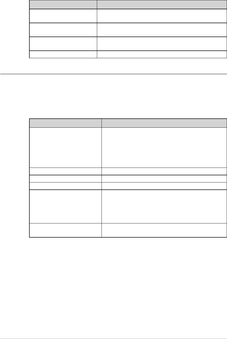
Cursor Movement Description
Move one character at a
time Press the Right or Left navigation key.
Move to the start of a
sentence Press the Up navigation key.
Move to the end of a
sentence Press the Down navigation key.
Add a space Press the 1 key.
Character sets
You can use character sets to change the style of the text, and to enter
numbers and special characters. The character set can be changed as often as
required when entering text. The following character sets are supported:
Character set Description
Auto-capitalisation (Abc)
The first letter is entered in upper-case, with
all following characters in lower-case. New
sentences start with a capital letter and end
with a full stop (.), question mark (?) or
exclamation mark (!) followed by one or more
spaces.
Upper case (ABC) All characters are entered in upper-case.
Lower case (abc) All characters are entered in lower-case.
Numeric (123) All characters are numbers.
Special characters(!.@)
You can select special characters such as full
stops (.), semi-colon (;) and commas (,) by
pressing the 0key. Further special characters
#@!”£$%&’()*+- are available on the #
key.
Chinese characters Simplified and Zhiyan. Chinese character sets
below
The selected character set is indicated on the status line at the top of the
display, next to the Battery Charge icon.
Chinese character sets
Simplified Chinese
You can build up Simplified Chinese characters by pressing the appropriate
keys on the keypad to input strokes. As strokes are entered they display in
72 SC20 series – 04/2016

the top left of the character selection box and the set of possible matching
characters is displayed above the Context keys.
You can also use pinyin to enter a phonetic version of a Simplified Chinese
character (e.g. ‘Lu’) which is displayed in the top left of the character
selection box—in the same place as the strokes described above—and the set
of possible matching characters is displayed above the Context keys.
When the right and/or left arrow icons are displayed in the character
selection box, use the Left and Right navigation keys to select from the
characters displayed. To see further characters press the Down navigation
key, and press the Up navigation key to return to characters already viewed.
The characters are displayed in sets of seven.
To enter the highlighted character—press Insert or press the Select/Send
key.
Zhiyan Chinese
Zhiyan Chinese characters are composed and entered in a similar way to
Simplified Chinese characters, however when the keys are pressed to input
the strokes that build up the character you must then press the Select/Send
key to display the set of possible matching characters.
User Guide 73
Messages
Your radio supports status messages, text (SDS) messages and
picture messages. All message types are available from the Messages menu.
Message Inbox
Incoming messages are displayed in the Inbox with the most recently received
messages at the top. Unread messages appear in Bold. The Inbox can store up
to 50 messages. When the Inbox is full, unsaved older messages are
automatically deleted when new messages are received. If you want to keep a
message, you must save it.
If your radio is configured to show messages in tabs, the most recent message
appears on the last numbered tab, for example if there are 5 messages in your
Inbox a new message will appear on tab number 6. If you want to read older
messages use the navigation keys to scroll through the message tabs. Unread
message appear on black labelled tabs.
Note: To keep the Inbox to a manageable size it is recommended that
messages are deleted or saved after reading them. See Saved messages on
page 77.
When a new message arrives
the New Message icon appears to show there is a new message in the
Inbox.
the radio vibrates
the tri-colour LED flashes amber
the blue LED flashes periodically (‘missed event’)
the display flashes periodically (‘missed event’)
if specified in the message, the text of the message (SDS message) or image
(Picture message) is displayed on the screen as soon as it is received
To open the Inbox:
Choose one of the following methods:
74 SC20 series – 04/2016
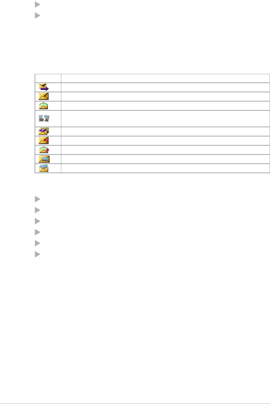
Press a customised soft key
Open the Shortcut Bar (in the Home screen press the Shortcut context key
or the Up navigation key) then navigate to the Inbox shortcut and press
the Select context key.
Message icons
Various icons are used to identify the type of message received:
Icon Description
Status message
SDS message (unread)
SDS message
Broken message: there was a problem receiving the message. Its
contents are lost or damaged.
Saved Messages is nearly full to capacity [customisable]
SDS message with Paging Alert (unread)
SDS message with Paging Alert
Picture message (unread)
Picture message
Inbox operations
Open the message
View the message details (See View message details on the next page.)
Reply to the message (not picture messages)
Forward the message to a contact (not picture messages)
Save the message(See Saved messages on page 77.)
Delete the message
User Guide 75
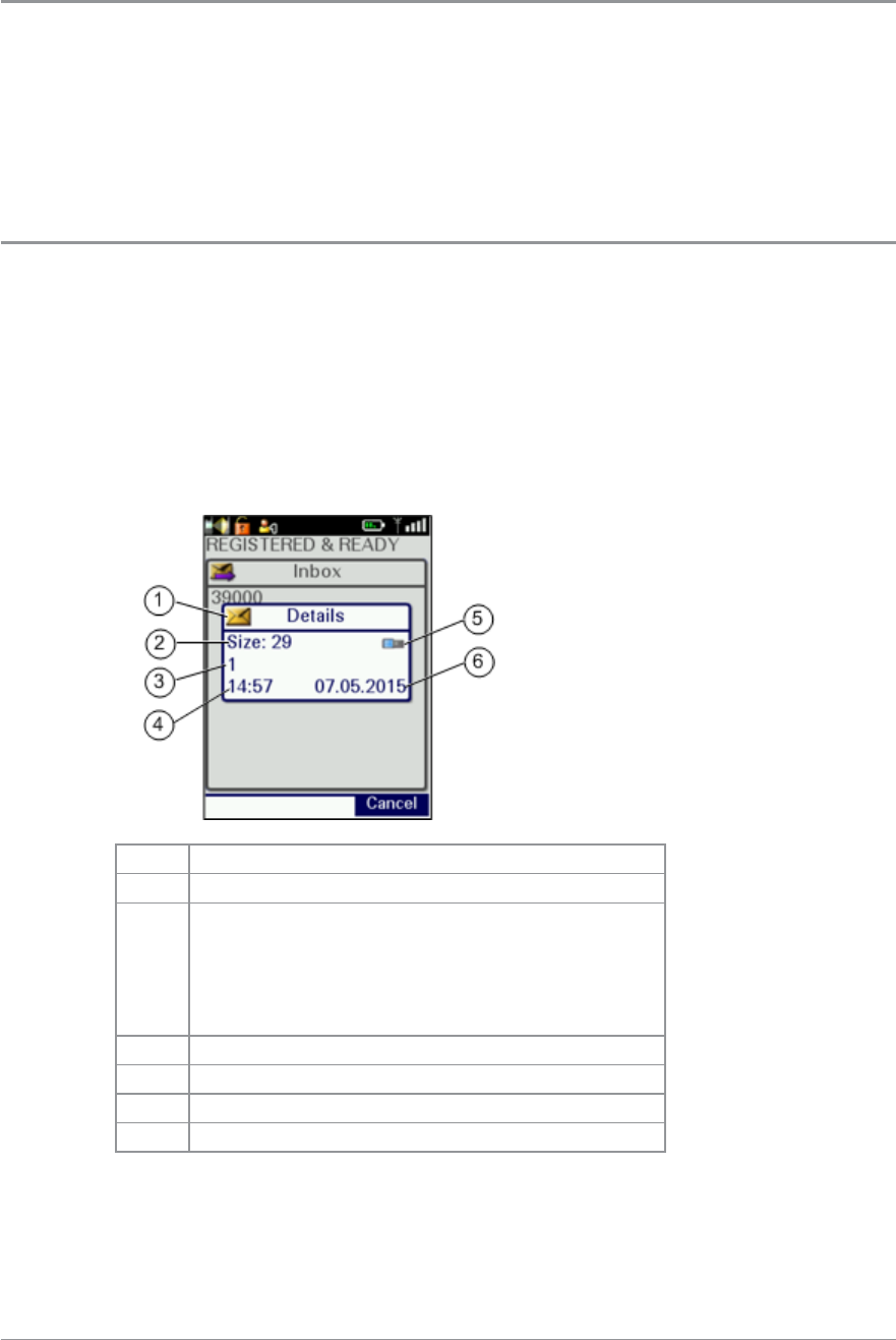
Opening messages
To open a message:
1. Open your Inbox (see To open the Inbox: on page 74).
2. Scroll to the message and then press the Open context key.
View message details
You can view the details of received messages.
To view message details:
1. Open your Inbox (see To open the Inbox: on page 74).
2. Select a message then use Options > Details.
3. To exit the Details screen press Cancel.
4.
Item Description
1 Message location (Inbox)
2
Size. Note: this is a relative measure of the
message size (not number of characters). You
can use Size to decide which message(s) to
delete if Saved Messages becomes full (see
Message Inbox on page 74)
3 Sender
4 Time received
5 Dial mode
6 Date received
76 SC20 series – 04/2016
Reply to a message
To reply to a message:
1. From an open message, select Reply.
2. From Inbox, select a message then select Options > Reply.
3. Create your response (see Text entry on page 71.)
4. When you have finished, press Send.
5. Select a recipient:
a. Send to Default—send to message sender
b. Send to Group—send to your current talkgroup
c. Phonebook—send to a contact in your phonebook
d. Dial—send to a number you dial
6. Press Send.
Open a URL in a message
Open the message then select Options > Open URL.
A text message may contain a URL which you can open in the WAP Browser.
Note: If your radio has been customised to do so, URLs in text messages
can open automatically in the WAP Browser when they are received.
Saved messages
You can save up to 50 messages in your Saved messages folder. When the
remaining space is insufficient to save a particular message, an error is
displayed which indicates the amount of space required to store the current
message. Delete one or more messages to clear some space for new ones to be
saved.
Caution: Saved Messages can be lost if the radio is not correctly switched
off when powering down (see Power off on page 23).
To save a message:
1. Open the message (or select it in the Inbox).
2. Select Options > Save.
User Guide 77
A message indicating that the message has been stored is displayed.
To view saved messages:
Select Menu > Messages > Saved Messages. Use the navigation keys to scroll
through the list of messages.
To delete saved messages:
1. View Saved Messages (see To view saved messages: above).
2. Select Options > Delete.
3. Select a delete option:
To delete the selected saved message select Delete Message
To delete all saved messages select Delete All
Create a text message
1. Select Menu > Messages > Create Message. An empty message box
appears.
2. Enter your message text (see Text entry on page 71).
3. EITHER:
send the message immediately
save the updated message
Tip: To return to the top level menu screen, either wait for the inactivity
timer to expire, or press and hold the Cancel/Home key, or press and hold
the ‘clear’ soft key.
To send the message immediately
See Sending messages on the facing page
Tip: You can set an option to confirm that the message has been
delivered, see SDS Report Request on page 81.
To save the message
Select Options > Save.
To edit a saved text message
1. View Saved Messages and select the saved message.
2. Select Options > Edit.
78 SC20 series – 04/2016
3. Edit the message as required. (See Text entry on page 71.)
4. EITHER:
send the message immediately
save the updated message
To send the message immediately
See Sending messages below
To save the updated message
Select Options > Save.
Sending messages
You can send text (SDS) and status messages to:
the currently selected talkgroup
the default destination customised in your radio (for example, the message
sender)
a Phonebook entry
a destination you key in
Note: For setting default destination see Set default destination on page 81.
1. Choose one of the following methods:
Create a text message (described on the previous page)
Select a saved text message (see Saved messages on page 77
Select a status message from the Send Status List (see Status messages on
page 1)
2. Select Send or Options > Send.
3. Select a destination (see below):
Send to default destination
Select Send to Default then select Send. The message is sent and the radio
returns to the message screen.
Send to current talkgroup
1. Select Send to Group. The current talkgroup is shown.
2. Select Send.
User Guide 79

Send to a Phonebook entry
1. Select Phonebook. Your Phonebook opens.
2. Select your contact and press Open.
3. Select the phone number. (Contacts can have multiple phone numbers).
4. Press Send to send the message.
Note: While you are selecting the address for a message you cannot make
outgoing calls to Phonebook.
Send to a dialled destination
1. Select Dial.
2. Key in an individual address (ISSI, Individual Short Subscriber Identity) in
the dial box.
3. Press Send to send the message.
Send a status message
To send a status message, choose one of the following methods:
Shortcut Bar
Press Shortcut to open the Shortcut Bar, then select Quick Status (if
customised).
From the Home screen
1. In the Home screen, double-press the Groups key.
2. Press the Left and Right navigation keys to scroll through the status
messages.
3. To send the message, press Send, then select Send to default (or choose
another destination such as your talkgroup, contact in your phone book or
dial the number).
Soft key (Quick Status message)
Press a soft key. Messages sent from soft keys are called Quick Status messages.
Note: During a Group Call with the call dialogue screen displayed, you
cannot send Quick Status messages using the Select/Send key or the
Cancel/Home key. Instead, first press the Down Navigation key to clear
the call dialogue screen, or exit the call.
80 SC20 series – 04/2016
Menu
1. Select Menu > Messages > Send Status.
2. Use the Up and Down navigation keys to highlight the status and then
select Options >Send.
3. Select a destination.
Edit status messages before sending
You can edit the text label of a status message prior to sending it. When the
message is edited, it is sent as a text message, rather than as a status message
code.
With the status message selected, press Options and then select Edit . Enter
your text before sending the message.
Tip: The Edit option is only available when you open a status message
from the menu.
SDS Report Request
You can request a Delivery Report and/or a Read Report when you send an
SDS (text) message. These cause a pop-up box to open when sent messages
are successfully delivered and read respectively.
1. Select Menu > Messages > SDS Report Status.
2. Navigate to a report type and press Toggle to toggle the report on (ticked)
and off.
Set default destination
You can enter and update the default destination address that your radio
offers when you send a status or SDS message. This can be either a talkgroup
or an individual.
1. Select Menu >Messages > Status Destination.
2. Select Options (or press the Select/Send key) then select Edit.
3. Select Dial or Phonebook:
select Phonebook to open the Phonebook and choose a contact
(Contacts on page 55)
select Dial to enter the required number directly from the radio keypad.
4. Press Save or the Select/Send key to save the number (or press Cancel or
the Cancel/Home key to cancel it and return to the previous number).
User Guide 81
Picture messages
Picture messages
Your radio can receive picture messages which may have accompanying text.
You may also be alerted by an alarm (if specified in the message) and
vibration and LED alerts (if customised). (You cannot reply to or forward a
picture messages.)
Tip: You can press any key to stop the audible alarm.
Open picture message
1. Select a picture message then click Open.
2. To view the image full screen, use Options > View Image.
The image and any text associated with it are displayed.
Note: If the image data has been corrupted the Broken Picture icon is
displayed.
Paging alerts
The Paging Alerts feature allows the radio to act as a pager when it is in
normal operating mode or when you select a user profile which results in the
radio appearing to be switched off. (See User profiles on page 107.) The
Paging Alerts feature is triggered by receipt of a Status message which is
automatically displayed.
If there is also an associated SDS message to explain the reason for the Paging
Alert this is automatically displayed on the radio. If a call is in progress the
Paging Alert interrupts it. The SDS message is marked with an icon to
indicate that it is associated with a Paging Alert.
When the Paging Alert is triggered you hear a discordant two tone alarm and
the tri-colour LED flashes amber to indicate that a Status message has been
received. To stop the two tone alert press any key.
82 SC20 series – 04/2016

Tip: Your radio can be customised so that a Paging Alert automatically
makes it fully operational on receipt of the Status message which triggered
the Paging Alert.
User Guide 83
Networks
Authentication
Remote User Assignment (aliasing)
If your radio supports Remote User Assignment (RUA) using TETRA
Interoperability Profile (TIP) defined procedures and transactions, your
presence on the network requires authentication.
RUA allows you to be authenticated onto the network by entering a user
identity and optionally a PIN (maximum 7 digit). Once accepted by the
system, you can be addressed by your user identity, if aliasing is supported by
the system.
At the start of a shift, you can take a pool radio and, after you log in, other
radio users on the network can identify you by you user name. TETRA
services including individual voice and data (Status and SDS) communication
can be set up using your user name (provided your user name and your
corresponding user ISSI are in the Phonebook).
Caution: If you power on your radio using the Emergency button you
must log on to the network before an Alarm call can be initiated.
Note: Network log on/off may be initiated by your dispatcher.
To log on/off:
Your radio may be customised to request PIN entry log on to the network
when powered on. Alternatively select Menu > Networks > Log ON/OFF.
A screen appears:
Log On—enter you user ID and password then press Confirm.
Log Off—press Confirm.
Details—indicates the current log on state of the radio. and displays the
user's network identity.
84 SC20 series – 04/2016
Change Network
You radio may be customised to use other networks when you move into
their coverage area.
To change network
1. Select Menu > Networks > Change Network.
2. Navigate to the required network then press Select or the Select/Send key.
Tip: To select the local network automatically, select the Automatic check
box. (Pressing the Cancel/Home key does not deselect a network.)
Transmit Inhibit
Sometimes you may be working in areas that are sensitive to Radio Frequency
(RF) signals such as healthcare facilities. To continue operating your radio in
these areas, you can set your radio to Transmit Inhibit mode to prevent any
RF transmission.
When Transmit Inhibit is activated or deactivated, a status message is sent
confirming the operational state of your radio. You cannot activate Transmit
Inhibit when you are in a call.
Caution: Alarm Calls initiated in Transmit Inhibit mode are still
transmitted.
Note: You cannot select Transmit Inhibit if user profile Do Not Disturb is
selected. See User profiles on page 107.
Note: Your radio automatically leaves Transmit Inhibit mode when you
power it off; when powered on again Transmit Inhibit is not activated.
To activate or deactivate Transmit Inhibit mode
1. Select Menu > Networks > Transmit Inhibit.
2. Select Toggle to toggle Transmit Inhibit on/off.
When Transmit Inhibit mode is activated:
User Guide 85
The Transmit Inhibit icon appears in the Shortcut Bar as a notification or
the status line on the Home screen
The Tri-colour LED flashes orange four times approximately every 2
seconds.
Tip: There may be a soft key programmed to toggle Transmit Inhibit
on/off. For a list of programmed soft keys refer to the radio's Help (Menu
> Help).
Fallback Mode
If a base station loses communication with the rest of the network, then any
radios using the base station continue to operate, but with a reduced service.
This is known as Fallback Mode. The base station broadcasts the loss of
communication to all radios which are using it.
In Fallback Mode your radio can only communicate with other radios that are
registered on the same site: no inter-site communication is available.
When your radio enters Fallback Mode:
the radio status bar indicates Fallback Mode and the yellow warning
triangle is displayed momentarily
the Fallback Mode text box pops up in the centre of the screen for a few
seconds showing a customisable text message
the RSSI antenna icon flashes continuously
the tri-colour LED flashes amber intermittently (indicating limited service
mode)
the radio generates a warning tone
When your radio leaves Fallback Mode:
the radio status bar returns to normal (Ready… or similar)
the RSSI antenna icon stops flashing
the tri-colour LED stops flashing
a text box pops up indicating normal operation.
the radio generates a warning tone.
86 SC20 series – 04/2016

Operating Modes
Your radio supports the following operating modes:
In Trunked Mode Operation (TMO Mode) your radio operates on the
network infrastructure supplied by your service provider.
In Direct Mode Operation (DMO Mode) your radio can transmit directly
to another radio (antenna to antenna). In DMO Mode radio coverage
depends on the position of the caller and the receiving radio. When you
switch to DMO your radio leaves the network and tunes to the selected
DMO talkgroup. See also DMO Mode on the next page.
In Repeater Mode your radio enables two or more radios operating in
DMO Mode to communicate over an extended range, automatically
relaying voice and messages by operating as a repeater. See also Repeater
Mode on page 91.
To change operating mode from the Home screen:
Press the Menu context key, then select Networks > Operating Mode. Scroll
to the mode (highlight it) and press Select.
Alternatively, a soft key may be programmed as a shortcut to this function or
a shortcut may be added to the Shortcut Bar. Open the Shortcut Bar (in the
Home screen press the Shortcut context key), scroll to the Operating Modes
shortcut and then press the Select context key. You can then select the
operating mode.
User Guide 87
DMO Mode
In Direct Mode Operation (DMO), radios communicate directly with other
TETRA radios without using a network. The radios must all switch to DMO
and select the same talkgroup, and that talkgroup must use the same channel
(frequency). Communications to other users on the network are impossible
unless they also switch to DMO and select the same talkgroup.
Note: This means that in DMO, communications to the dispatcher is
impossible unless they also switch to DMO and select the same talkgroup,
or if they communicate through a DMO gateway (see DMO gateway
operation on page 1).
Group calls
DMO supports group calls (see Group calls on page 62) which are made and
received in the same way as radios operating in TMO. In DMO TETRA Alarm
Calls are either sent to the currently selected DMO talkgroup or (if
customised) may switch to TMO to make the call. If TMO is unavailable
Alarm Calls are made using DMO. See Emergency operation on page 33.
Individual calls
Your radio can be customised to allow you to make individual calls to other
radios working in DMO which are attached to the same talkgroup. In this
case individual calls are initiated by pressing the PTT key. See Making
individual calls (half-duplex mode) on page 64. (Individual calls to radios which
have selected different DMO talkgroups are prevented unless the DMO
talkgroups have the same carrier frequency.)
Your radio can also be customised to allow you to select a channel only
talkgroup. If you select a channel only talkgroup your radio cannot make or
receive group calls: it can only make or receive individual calls.
Tip: You can enable Presence Checking so that your radio checks
whether the receiving radio is available to receive when you attempt an
Individual call. See DMO options on page 90.
88 SC20 series – 04/2016
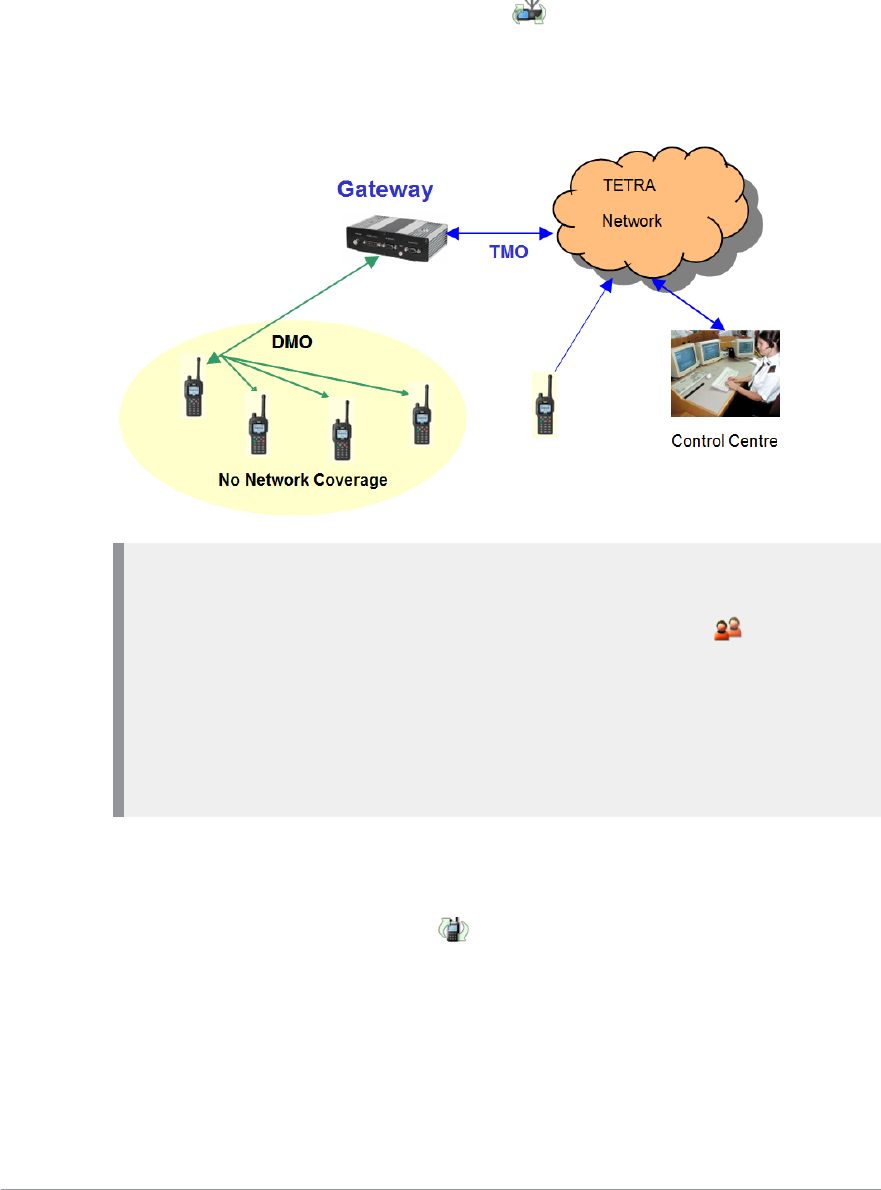
Using a DMO gateway
A DMO gateway (or gateway) is a device which allows users working in
Direct Mode to communicate with users in Trunked Mode effectively
extending the working range of a radio. When your radio is in DMO Mode
and it is in range of a DMO gateway the gateway icon appears and, if
customised, an audible alert is generated. You can now make and receive
group calls to TMO radios (and to the dispatcher) via the gateway. See DMO
gateway operation on page 1.
Note: If your radio is outside the range of a gateway, you may still be able
to hear the speech of another user who is in range of a gateway and who
is involved in a group call via the gateway. In this case the
Communication Mismatch icon is displayed to indicate that you cannot
take part fully in the call. If you attempt to respond to the overheard
speech, any radios within gateway range which can hear you also display
a Communication Mismatch icon to tell them that the speech is not being
routed via the gateway to TMO users.
Using a DMO repeater
You can extend DMO Mode range by using a DMO repeater (repeater). If
your radio detects a repeater the DMO Repeater icon is displayed and
your radio can communicate with any other radios in the selected DMO
talkgroup which are also within the range of the repeater. See Repeater Mode
on page 91.
User Guide 89
Note: If a radio is within range of a repeater but for some reason a call
cannot be set up through it your radio attempts to set up the call in DMO
Mode and the Communication Mismatch icon is displayed to all
members of the talkgroup to indicate that there may be members of the
talkgroup who cannot take part in the call.
DMO options
You can select the following DMO options:
Presence Check
Specify whether Presence Checking is performed before DMO Individual
calls are made. When Presence Checking is On your radio checks whether the
intended receiving radio is available and in radio contact before it attempts to
set up the call.
GW/Rep Filter
Specify whether your radio uses or ignores any gateway and/or repeater it
detects.
In the Gateway/Repeater Filter screen select one of the following options:
No GW/Rep—do not use any gateways and repeaters detected by your
radio
Use Repeater—Use repeaters detected
Use Gateway—Use gateways detected
Use GW/Rep—Use a gateway or a repeater detected by your radio.
Note: When option Use GW/Rep is selected, your radio selects the first
gateway or repeater that it detects. If it selects a gateway, a gateway
icon is displayed on the status line. If the gateway stops sending a
presence signal it will no longer be detected by your radio which may
then detect a repeater. In this case the gateway icon is replaced by the
repeater icon on the status line.
Therefore when you are making a call look at the display to understand
how it will be made. Take care if a repeater and a gateway are using the
same frequency and your radio is configured to use both devices (that is,
option Use GW/Rep is selected).
90 SC20 series – 04/2016
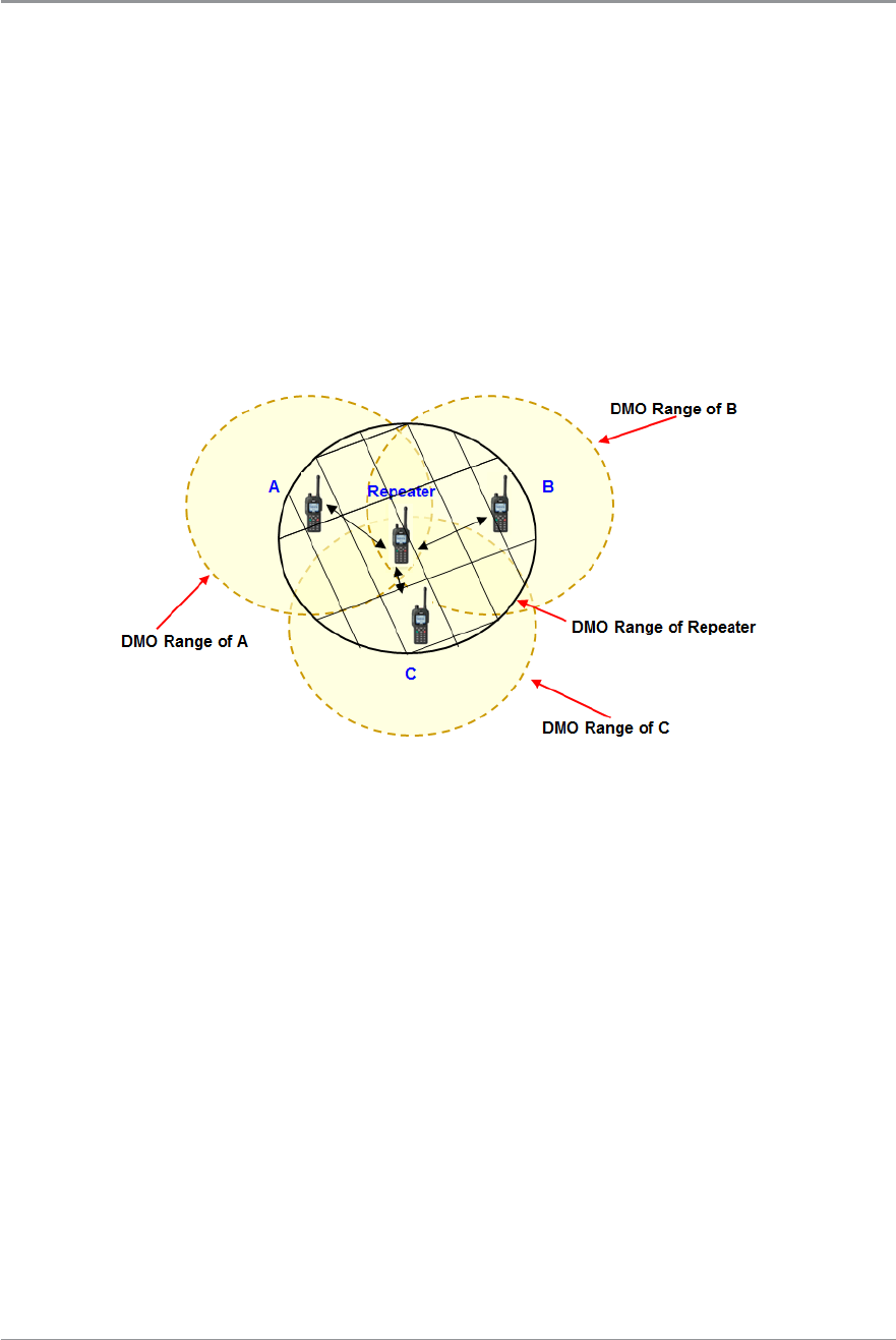
Repeater Mode
A radio acting as a repeater provides a service to other radio users. It extends
the range and enhances the reliability of Direct Mode communication
compared with basic direct communication between radios.
You can use a repeater to enable communication between radios which are
out of range of each other. The following diagram shows radios A, B and C
and a repeater which are on the same DMO talkgroup. A, B and C are in
range of the repeater. Because of its location, the repeater can pass
communications between A, B and C even though they are out of range of
each other.
You can also use a repeater to enable communication between two radios
which cannot communicate directly, perhaps because their users are do not
have line of sight with each other.
The following diagram shows radios A and B and a repeater which are on the
same DMO talkgroup. A and B are in range of the repeater. Because of its
location, the repeater can pass communications between A and B even
though they cannot communicate directly.
User Guide 91
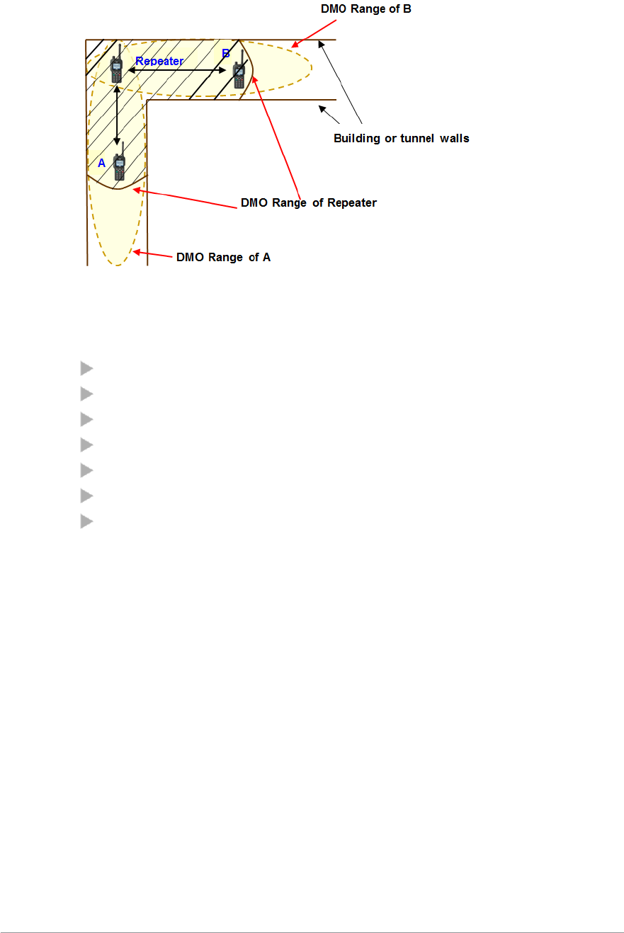
What repeaters cannot do
In Repeater Mode the radio cannot:
make individual calls
take part in another group call
send status or SDS messages
use the Quick Status feature
edit text
use the phonebook
view the library of pre-defined Status messages
Participating in repeated calls
A radio in Repeater Mode may (depending on its customisation) operate
either as a Standard Repeater or as a Repeater with Call Participation.
Standard Repeater
If your radio is configured to operate as a Standard Repeater you cannot take
part in calls which are being relayed through it.
Repeater with call participation
If your radio is configured to operate in Repeater Mode with Call
Participation you can take part in the calls which are being relayed through it
if the call participants are on the same DMO talkgroup as you. To stop
participating in a call, press the Clear context key; you radio continues to act
as a Repeater.
92 SC20 series – 04/2016

Note: You cannot switch to Repeater Mode if the radio is in Transmit
Inhibit on page 85 or if the radio has initiated an alarm call (see Emergency
operation on page 33) which has not been cleared.
Caution: If you select Transmit Inhibit Mode while your radio is
operating in Repeater Mode, the radio leaves Repeater Mode and it stops
functioning as a Repeater.
Note: If you are going to leave a repeater unattended for long periods of
time, or as a permanent installation in a remote location, we recommend
that you configure it as required (select and attach the required Direct
Mode talkgroup) and then power the radio off. This will save the
configuration; each time the radio is powered on again, it will re-start with
the saved configuration. This will ensure that the radio is always running
with the correct repeater configuration even if it turns on unexpectedly
after circumstances such as power failures.
Switching to Repeater Mode
To switch to Repeater Mode see Operating Modes on page 87.
Note: Before you can use the radio as a repeater you must select a Direct
Mode talkgroup.
Changing talkgroups in Repeater Mode
You can change talkgroups while your radio is operating in Repeater Mode in
the usual way (see Talkgroups and folders on page 46.)
Caution: If you change to a different DMO talkgroup it may (depending
on the customisation) terminate any calls active through the repeater.
Using the Emergency Button in Repeater Mode
Caution: If you use the Emergency Button when your radio is operating
in Repeater Mode, any calls that are currently active through the repeater
will cease. When the Alarm Call is subsequently cleared, the radio may not
necessarily remain in Repeater Mode.
User Guide 93

Repeater states
A radio acting as a repeater can enter several states of operation, depending
upon the status of calls through the repeater and whether it has detected
other users of the direct mode channel. These states are reported as the
following top level screen messages:
Message Description
Ready: Repeater The repeater is ready and has no calls in progress
Busy DMO
Channel
The repeater has detected that the DMO channel is
being used. In this case repeater operation is
suspended.
In Call: Repeater A call is in progress through the repeater.
Talk Repeater Participating in a call and transmitting
94 SC20 series – 04/2016

Callout alerts
Your radio can receive Callout Alerts sent over the network to inform you of
incidents. When a Callout Alert arrives the radio sounds an audible alarm and
a Callout message is displayed on the screen. To silence this alarm press any
key. A voice call may also be initiated. Your radio may also be customised to
alert you of Callouts in other ways (such as vibrator alert and/or a flashing
LED alerts).
When it receives a Callout Alert your radio goes into Protected Callout Mode
on page 99 (in which many features are disabled) for a set time period or until
you respond to or acknowledge the Callout message. This mode is designed
to stop you getting distracted and to focus your attention on an incident.
To view Callout messages
Press Menu then select Phone > Callout.
Alternatively, press the Up navigation key (or Shortcut) to open the Shortcut
Bar, then select Callout.
If Callout messages have been received they are listed with Callout icons on
page 101.
To see the options for a Callout
Highlight a Callout and press Options OR
press the Select/Send key to activate the first option in the Options menu.
(The Select/Send Key Shortcut icon between the Context keys indicates
that this shortcut is available.)
Open – view the Callout message plus more information associated with the
message dialogue
Accept – indicate you are accepting the Callout
Reject – indicate you are rejecting the Callout
User Response – compose a free-form text message to send to the Callout
originator[customisable]
Delete – delete one or more Callouts
User Guide 95

Details – view the details of the Callout message
Status – send or update your current Availability status. The Callout screen
indicates that an Availability Status message has been sent. [customisable]
Responding to Callouts
When you respond to a Callout your radio may automatically send a message
(if programmed in the radio) or you can select a message from a list or select
User Response (if customised) to compose and send a free-form text message.
Callouts requiring a response
Some Callouts require a response. The following responses are possible:
Accept
Press Accept to indicate that you intend to act on the Callout (or select
Accept from the pop-up menu displayed from the Left or Right navigation
key. If only one acceptance message is programmed in your radio an
informative message is displayed to show that it has been sent to the
originator of the Callout. If multiple messages have been programmed, select
one of them and press Select to send it. Alternatively (if customised) you can
compose and send a free-form text message.
Depending how the Callout has been configured it may either exit once the
acceptance message has been sent or it enter an Information Phase during
which information may be sent to and received from the originator of the
Callout. This could include a pre-set message, a free-form text message or a
Callout group call. Information Phase on page 103.
Reject
Press Reject to indicate you do not intend to act on the Callout (or select
Reject from the pop-up menu displayed from the Left or Right navigation
key. Your radio exits from the Callout and Protected Callout Mode and the
top level screen is displayed.
Standby
Select Standby to acknowledge receipt of the Callout and to indicate that you
are “standing by” for further information before accepting or rejecting.
96 SC20 series – 04/2016

During standby the Callout goes into its Information Phase during which
information may be sent to and received from the originator of the Callout.
During standby you can also accept or reject the Callout and—if use of the
PTT is permitted—make group calls to the Callout group (See Group calls to
Callout group on page 102.)
During Standby you can view the following Callout message details :
the ‘Response required’ icon
the Callout group
time and date when the message was received
the severity of the Callout Alert
the Callout ID
icons to show:
whether the Callout is to a group or an individual
whether the Callout is incoming or outgoing
whether or not the Callout is End-to-End Encrypted
User Response
Allows you to compose and send a free-form text message to the originator of
the Callout.[customisable]
Callouts not requiring a response
Some Callouts do not require a response. You can respond to or ignore then
as follows:
Exit
Press the Exit context key to exit the Callout and exit (see Protected Callout
Mode on page 99), and return to the top level screen. No response message is
sent.
Respond
Press the Respond context key to display the Information screen offering the
various pre-set messages to send from the radio to the originator of the
Callout and vice versa. To send one of the pre-set messages select it and press
the Select context key.
User Guide 97

User Response
You can compose and send a free-form text message to the originator of the
Callout. When your message is ready to send press the Confirm context key.
You can continue to respond and send messages as described here until the
Callout ends and the top level screen is displayed.[customisable]
Details
You can view the following Callout message details:
the ‘Response required’ icon
the Callout group
time and date when the message was received
the severity of the Callout Alert
the Callout ID
icons to show:
whether the Callout is to a group or an individual
whether the Callout is incoming or outgoing
whether or not the Callout is End-to-End Encrypted
Callout Test alert
If you receive a Callout Test Message either respond or cancel the alert:
to cancel the Callout Test alert press the Cancel context key. The Callout
exits and the radio displays the top level screen. You can still view the
details from Messages > Callouts.
to indicate that you are ready to respond to Callout alerts press Respond
(or the Left or Right navigation key). The following response options are
displayed:
Respond
Press the Respond context key to display the Response screen. Press the
Right or Left navigation key to view additional options. To send a Test OK
message to the Callout originator select it and press the Select context key.
The Callout Test exits and the top level screen is displayed.
User Response
(If customised) allows you to compose and send a free-form text message to
the originator of the Callout. When the message has been sent the Callout
98 SC20 series – 04/2016

Test exits and the top level screen is displayed.
Details
The Details screen is displayed showing:
the Callout Test icon
an indication that the Callout Test has been sent to an individual
the originator of the Callout Test message
time and date when the message was received
the severity of the Alert
the Message ID
icons to show :
whether the Callout is to a group or an individual
whether the Callout is incoming or outgoing
whether or not the Callout is encrypted
Press the Back context key to display the previous screen.
When a Callout ends
When a Callout times out or is cleared by the Callout originator the Callout
ends, your radio displays the top level screen and the functionality which had
been suspended is restored.
Protected Callout Mode
When it receives a Callout alert your radio goes into Protected Callout Mode
(and many features are disabled) for a set time period or until you respond to
or acknowledge the Callout message. This mode is designed to stop you
getting distracted and to focus your attention on an incident.
During Protected Callout Mode you can only do the following:
Read the current alerting message
Acknowledge the Callout alert
Make an Alarm Call
Switch Transmit Inhibit on/off
Make a Quick Call (if customised as a higher priority than Callout)
Switch on Man Down
User Guide 99

React to the Lone Worker prompts. The Lone Worker alarm operates if
you do not react.
Switch the radio off using the Mode key
No calls—apart from group calls allowed by some Callouts—received while
your radio is in Protected Callout Mode are connected but their details are
saved. To view them after the Callout has ended select the Missed Event
menu.
If you receive a new Callout while your radio is already in Protected Callout
Mode, the new Callout takes priority and is displayed immediately. The
existing Callout is treated as a missed Callout: to view its details after the
Callout has ended select Messages >Callout. The blue LED flashes and the
Missed Call and/or Missed Callout icons display after the new Callout has
ended.
Missed Callouts
To view information about the missed Callout select Menu > Messages >
Callout.
Your radio ignores Callouts received when any of the following functions are
active:
Ongoing Alarm Call (a highest priority call)
Alarm Call
Quick Call (when customised as a higher priority than Callout)
Smart Call 1 (when customised as a higher priority than Callout)
Smart Call 2 (when customised as a higher priority than Callout)
Group Focus
Privacy Mode
Man Down
Lone Worker
When the higher priority function ends, the radio notifies you of the missed
Callout by sounding an audible alert, flashing a blue LED (missed event) and
displaying a Missed Callout icon.
100 SC20 series – 04/2016
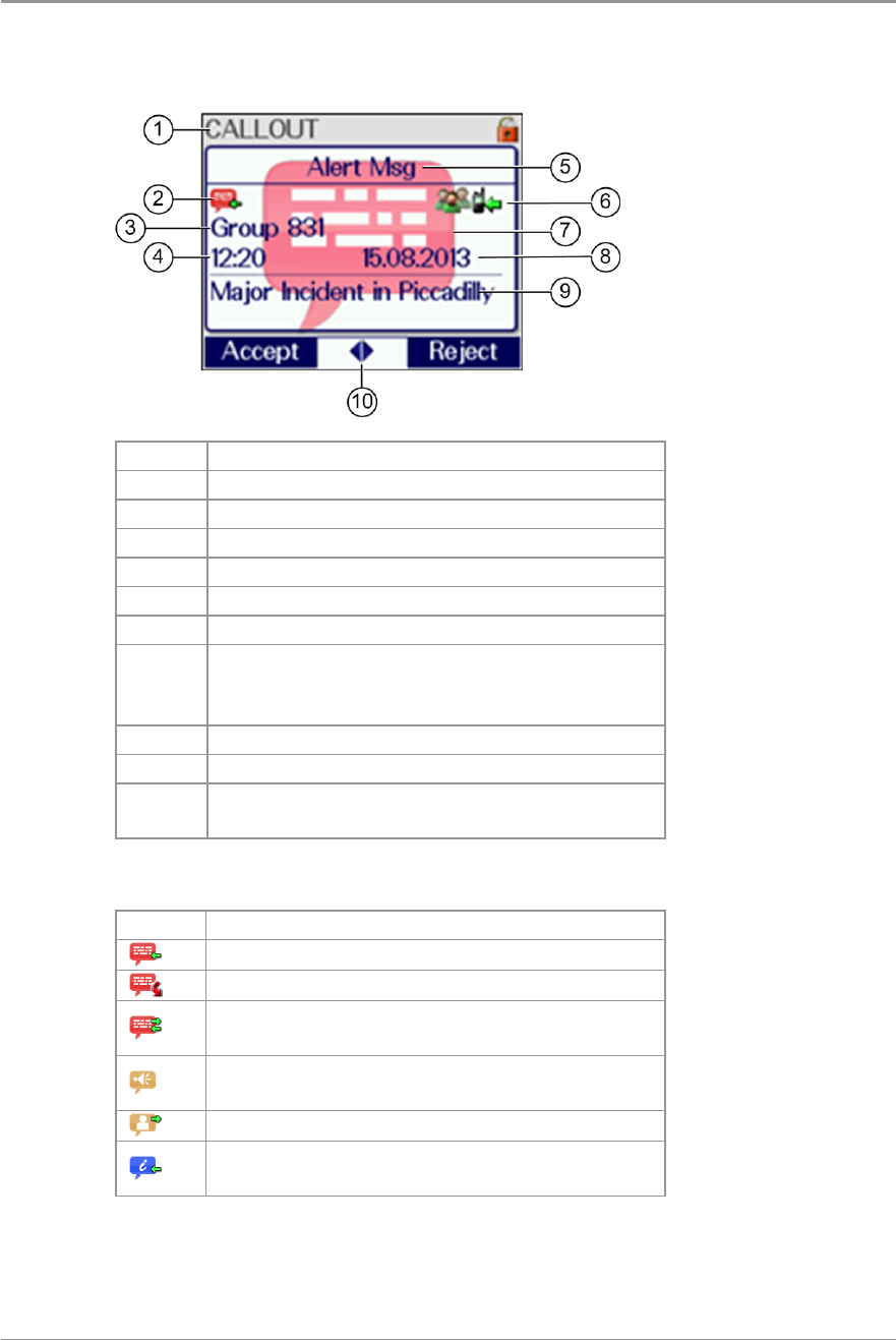
Callout display
A typical Callout screen looks as follows:
Item Description
1 Message location (Inbox)
2 Callout type, see Callout icons below.
3 Callout group or Callout originator
4 Time received
5 Callout message header text (customisable)
6 Information icons
7
Backdrop image (customisable, radios with
colour display only). Indicates severity of
the Callout.
8 Date received
9 Explanatory text about the Callout
10 Left/Right Navigational keys available for
more options
Callout icons
Icon Description
Callout Alert message, response required.
Missed Callout
Callout Alert message, user response has
been sent.
Callout Alert message, response not
required.
Callout Availability message.
An information message has been received
by the radio.
User Guide 101
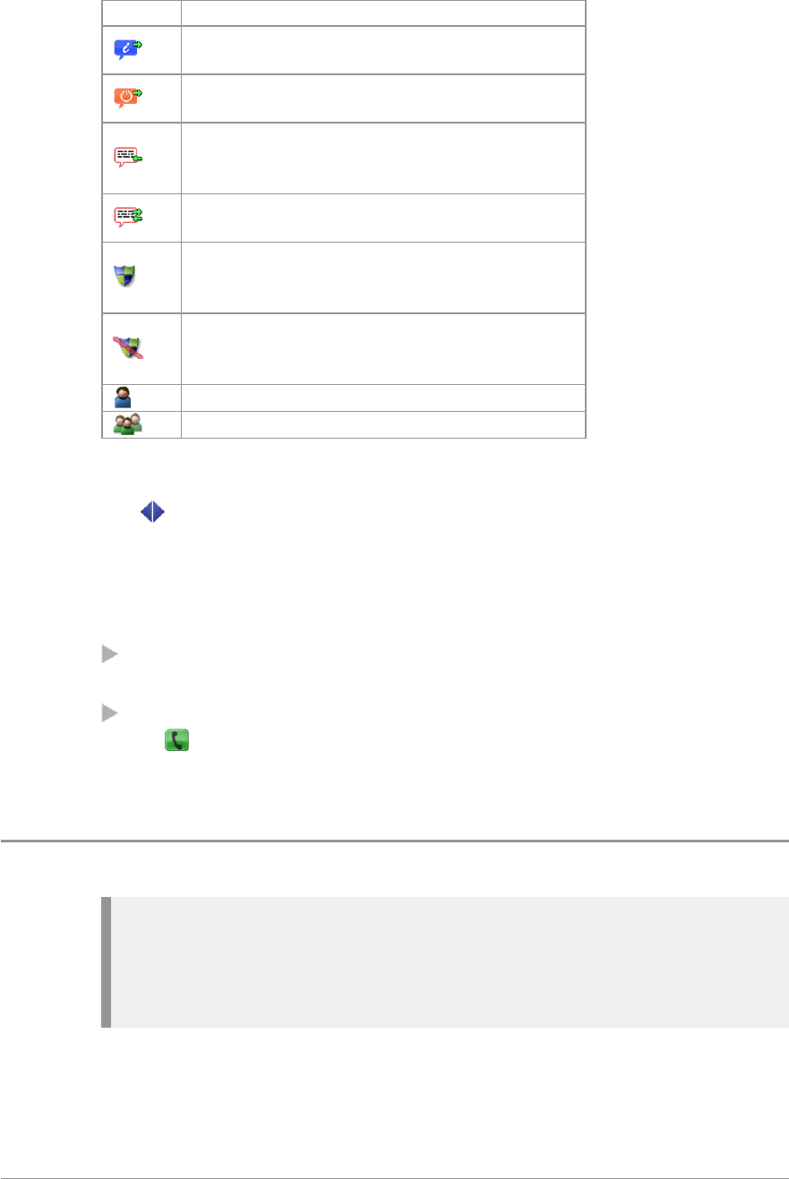
Icon Description
An information message has been sent
from the radio.
Standby Message has been sent from the
radio.
Callout Test message, user response is
required. The identity of the sender is
displayed instead of the Callout group.
Callout Test message, user response has
been sent.
The receiving radio and the Callout
originator both have End-to-End
Encryption active.
Either the Callout originator or the
receiving radio has End-to-End Encryption
switched off.
The Callout is addressed to an individual.
The Callout is addressed to a group.
Left and Right navigation keys
The left and right arrow icons are displayed between the Context keys
during Protected Callout Mode when there are more options than are shown
on the Context keys.
EITHER:
Press the Left or Right navigational keys to display a menu of the
additional options available OR
press the Select/Send key to action the first item in the menu of options.
The Select/Send Key Shortcut icon is displayed between the context
keys to indicate that this shortcut is available.
Group calls to Callout group
Note: While your radio is in Protected Callout Mode the only calls you
can make are TETRA Alarm Calls, Quick Calls (if customised as a higher
priority than Callout), and, if allowed, group calls to the Callout group.
You can only make group calls if PTT use is permitted during the Callout.
For some Callouts your radio can make and/or receive group calls to a
specially configured Callout group when it is in Protected Callout Mode. This
102 SC20 series – 04/2016

group may be the group the radio is attached to when the Callout is received,
or a different group which the radio is configured to connect to on receipt of
the Callout or when an acceptance message is sent.
While the PTT is pressed and the radio is transmitting the text “Talk” is
displayed in place of “CALLOUT” on the Radio Status Line at the top left of
the screen and no backdrop is displayed. When the radio is receiving a group
call the ISSI (or shortened ISSI) or identity of the transmitting party is
displayed in place of “CALLOUT” on the Radio Status Line at the top left of
the screen.
When the Callout has exited, depending on the customisation, the radio
either reattaches to the group it was attached to before receiving the Callout,
or remains attached to the new group.
Information Phase
Some Callouts do not exit after the initial acknowledgement is sent, but enter
an Information Phase when information may be sent to and received
from the originator of the Callout. Information can include a pre-set message,
a free-form text message or a Callout group call. Your radio can also be
customised to display a backdrop graphic to indicate it is in Information
Phase.
When information is sent (for example “Will Respond”) it is displayed and
the information sent icon displays.
Press the Exit context key to exit from the Callout or the Respond context key
to use an option on the Information screen or press a Left or Right
navigational key to display a menu of further options.
For some Callouts, group calls can be made by the radio to the Callout group
during the Information Phase if use of the PTT is permitted during the
Callout. See Group calls to Callout group on the previous page.
The options available during the Information Phase are Information, Accept,
Reject, User Response and Details.
Information
Send a pre-set information message. If only one Information message is
programmed in the radio you are notified by an informative message
User Guide 103

confirming that the pre-programmed Information message has been sent to
the originator of the Callout.
Alternatively you can select from a list of preconfigured messages. Select
View Response to check the complete message text before sending it.
Accept
Sends an acceptance message to the originator of the Callout.
Reject
Send a rejection message. You are notified by an informative message
confirming that the rejection message has been sent to the originator of the
Callout, and your radio exits from the Callout and Protected Callout Mode
and the top level screen is displayed.
User Response
Send a free-form text message (see Text entry on page 71Text entry on page 71
Details
See the following Callout details:
the ‘Response required’ icon
the Callout group
time and date when the message was received
the severity of the Callout Alert
the Callout ID
icons to show:
whether the Callout is to a group or an individual
whether the Callout is incoming or outgoing
whether or not the Callout is End-to-End Encrypted
104 SC20 series – 04/2016
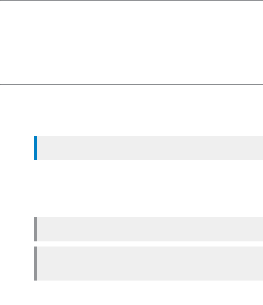
Features
Your radio can be customised for various advanced features and can have
various soft keys assigned to frequently used features.
Privacy Screen
Your radio can be customised to display a picture when the screen is inactive
for a specified period of time. This helps protect the privacy of any displayed
information. This Privacy Screen feature is particularly useful if you are
wearing your radio at shoulder level. The normal display reappears as soon as
any activity occurs which turns on the back light.
View images
Your radio needs to be fitted with a microSD card if you need to refer to
images on your radio, such as maps, product diagrams or photographs, or if
you will be referencing WAP sites.
Tip: Image details are best viewed in Normal Text Mode. See Adjusting
text and icon size on page 42.
After fitting, images and WAP sites are uploaded to the card using Radio
Manager. During customisation the data is encrypted to prevent undesirable
viewing of the data by unapproved persons should the radio or card be lost.
Only JPEG images can be used with your radio and images must not excess 2
mega pixels.
Note: Your radio supports microSDHC 32 GB cards that must be
formatted for the FAT16 file system.
Note: The error No SD Card indicates that your radio is not fitted with a
microSD card. The error No Entries indicates that there are no files on
the microSD card, orthat the card is correctly formatted.
User Guide 105
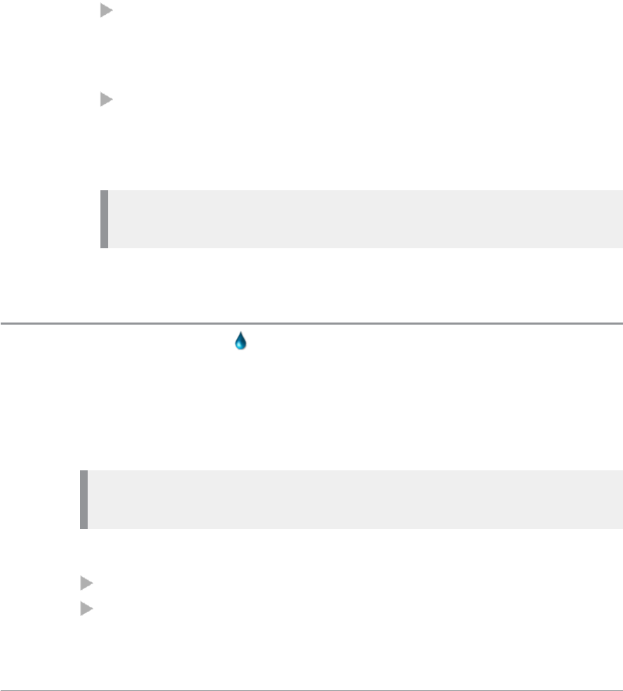
To view images:
1. Press Menu > Applications > View Images.
2. Use the navigation keys to select an image.
3. Press View.
4. To view information related to the image you are viewing, press Details.
Use the Up and Down navigation keys to show any details which cannot
be displayed on one screen.
Comments can provide useful information related to the image.
For example:
if the image was of a missing or wanted person, details could include
information about who to contact if that person is spotted, perhaps
advice on how to approach them and whether back up needs to be
called.
if the image was of a chemical symbol on the side of a tanker
transporting hazardous material, the comments could give advice on
what precautions need to be taken when dealing with the incident.
The date and time and other details are also shown.
Note: No details are available if the image has been loaded on to the
microSD card as a Bitmap.
5. To exit the image, press the Cancel context key.
Connector Protector
When working in salt water environments or in an area with high salt-laden
humidity such as sea mist or fog, enabling the Connector Protector feature
will protect the Digital Accessory connector (sDAC) from potential corrosive
damage when an accessory is not attached.
Note: A cover must be fitted to the Rugged Accessory Connector (RAC)
(on the side of the radio) if an accessory is not attached.
This feature can be enabled by:
a Soft key
selection of an option on a SmartMenu
106 SC20 series – 04/2016
selection of a user profile
automatically at power on after a configured time delay
selecting Connector Protection from the Options menu
To enable Connector Protector:
1. Press Menu then select Options > Settings > Connector Protection.
2. To toggle protection on/off press the Toggle context key. When the CP
Enable check box is ticked, Connector Protector is enabled, and when the
check box is empty it is disabled.
If Connector Protector is enabled ( ) when the radio is powered off, it will
remain enabled when the radio is next powered on unless the radio is in a
charger or car kit or if a data accessory (e.g. programming lead) is attached
when the radio is powered on, in which case Connection Protector is disabled
( ) until the radio is removed from the charger, car kit or data accessory. In
these circumstances it is not necessary to re-enable Connector Protector.
Tip: If the ‘water drop’ icon ( ) is displayed on a radio, the radio cannot
be programmed.
User profiles
User profiles are pre-set combinations of alerts and settings on your radio.
They allow you to switch settings easily to match your circumstances or
environment. An icon showing the number of the profile selected,
appears on the status line or the Shortcut Bar. Up to ten pre-defined user
profiles may be configured for your radio. Example user profiles could be
Normal,Lone Worker and Covert.
To change the user profile:
1. From the Home screen, press the Groups context key 3 times ( User
Profiles).
2. Use the navigation keys or the Navi-knobto scroll through the user
profiles.
3. Press the Select context key to activate the selected user profile.
User Guide 107
Menu selection
1. Select Menu >User Profiles.
2. Navigate to a profile and press Select.
Example user profiles
Typical profiles could include:
Covert Mode operation
Covert Mode turns off all visual alerts. It deactivates the backlight and adjusts
the microphone sensitivity to allow Whisper mode. It also reduces the level of
the loudspeaker if an earpiece is not being used. If your radio has a vibrator
alert enabled then this is deactivated. See Whisper mode on page 37.
Lone Worker operation
This user profile activates the Lone Worker function to allow users working
alone to indicate that they are safe. See Lone Worker on page 112.
Group Focus
This user profile allows you to prevent any individual calls or group calls
from any talkgroup other than the selected talkgroup from being connected
to your radio.
Note: Any calls made to a radio which has Group Focus selected are not
recorded as Missed Calls.
Do Not Disturb
This user profile allows you to focus on an important task. It assumes you do
not want to be distracted by a call or alert on your radio. The profile sets your
radio so that no incoming calls are allowed except calls from the current
talkgroup (Group Focus above). Covert Mode operation is active. Audible
alerts are disabled. In this profile is selected you cannot select Transmit
Inhibit (see Transmit Inhibit on page 85
Connector Protector
This user profile activates the Connector Protector feature when working in
salt water environments. See Connector Protector on page 106.
108 SC20 series – 04/2016
Man Down
Man Down is a licensed customisable feature which uses motion sensors to
detect motion in three dimensions. When your radio is powered on it stores
it's current angle of inclination (orientation). If it moves more than a
customised angle from the original inclination or is stationary for more than a
customised length of time, the radio sounds an alarm and displays a ‘Man
Down Alarm’ message. In other words the radio can detect conditions
indicating that you have become incapacitated. If you do not respond to the
alert within a customised time period, your radio initiates a Man Down
Emergency and takes action depending on its customisation.
Warning: Although Man Down is intended to increase the chances of
incapacitated users being detected, you should not regard it as a
substitute for compliance with appropriate risk assessment and other
safety procedures and practices. Do not entrust your safety to the Man
Down Alarm.
Warning: Test the Man Down Alert and Alarm regularly to ensure
they are functioning correctly.
Warning: Once started the Man Down Alarm sounds either until you
switch it off (see Cancelling false alarms on the next page) or until the
battery runs down. Ensure that the battery is charged regularly and
check that it has as much charge as possible before activating Man
Down.
Note: Man Down is disabled if the radio is placed in a car kit or charger.
Note: The Man Down feature may be customised so that you do not have
access to the following:
—the soft key On/Off toggle or a user profile to switch the feature on and
off;
—the Man Down screen to select the sensor or combination of sensors
used as described below.
User Guide 109
To toggle Man Down on/off:
1. Activate Man Down using one of the following methods:
Press a customised soft key to toggle Man Down on. The sensors
activated are those set in Man Down options on the facing page.
Select a user profile which uses Man Down (see User profiles on page
107). The sensors activated are those customised in the profile.
From the Home screen, press the Shortcut context key, then select the
Man Down icon.
A message (‘Man Down Starting’) is displayed and an alert sounds (a
succession of beeps).
2. Attach your radio in a comfortable wearing position on your body. When a
two second continuous tone finishes the radio’s ‘normal’ wearing position
has been recorded. An icon indicates that Man Down is switched on and
which sensors are active.
To deactivate Man Down, either select a user profile which does not use Man
Down, or press the customised soft key to toggle Man Down off.
Cancelling false alarms
If the active sensors detect a possible ‘Man Down’ situation the Man Down
Alert is sounded and a Man Down Alert message is displayed on the screen.
If you are safe (that is, this is a false alarm) you need to switch off the
alert, otherwise a genuine Man Down Emergency situation is considered to
have occurred and—depending on the customisation of your radio—various
automatic actions are initiated. For example, an Emergency Status message
may be sent to a pre-defined destination.
To switch off the Man Down Alert (false alarm situation):
press a designated key (which is different from the soft key used to switch
Man Down on and off) or
move the radio vigorously for a short period of time (if customised).
For example shake the radio up and down or sideways, or tap it, or (if the
radio is clipped to your belt) move your hips rapidly from side to side.
Note: After the Man Down Alert is switched off your radio may be
customised to start recording and storing the current position and/or
angle to use as the new ‘steady’ position.
110 SC20 series – 04/2016

Man Down options
1. Press Menu then select Applications > Man Down.
2. Select the Man Down sensors to use: Motion & Tilt sensors, Motion
Sensor only, or Tilt Only sensor.
If you enable Man Down from a User Profile, the Man Down Settings screen
updates to reflect the sensors defined as active in the Profile.
User Guide 111

Lone Worker
If you are working alone you can use the Lone Worker feature to let your
dispatcher know that you are safe.
When Lone Worker is enabled your radio periodically sounds an alert which
you must acknowledge—usually by pressing a pre-programmed key—
otherwise the radio sends an emergency status message to your dispatcher.
To enable Lone Worker, scroll to a user profile which has Lone Worker
enabled, then press the Select context key. See User profiles on page 107.
To disable Lone Worker mode, repeat the process and but choose a different
user profile.
112 SC20 series – 04/2016

WAP
Your radio may be configured to browse WAP websites. The browser options
are customised using Radio Manager, and some WAP pages may be stored
locally on the radio's microSD card.
Starting the WAP browser
To open activate the WAP browser:
EITHER
press the Up navigation key (or Shortcut) to open the Shortcut Bar, then
select WAP Homepage.
select the WAP option from the Applications menu OR
press a programmed soft key [customisable] OR
open a WAPURL contained within a received SDSmessage (or your radio
may be customised to open the WAP URLautomatically). Open a URL in a
message on page 77.
Using WAP
Exiting the browser
Exit at any time by pressing Back or the Cancel/Home key (if customised).
Navigation
Press the Left navigation key to display the previous screen/page and the
Right navigation key to display the next screen/page.
Entering text
If customised, your radio supports the entering of text to specify a URL and
entering of data into a form, and so on. See Text entry on page 71.
Saving check box or radio button selections
Sometimes you may need to select an option which has a check box or radio
button. When setting an option that uses a check box or radio button, toggle
User Guide 113

the left context key to select the appropriate option (radio button or check
box). To save the selection either scroll to the bottom of the screen and
highlight the Save button or press the Left context key (either a tick icon or
labelled Save depending on customisation).
Browser menu
Home Page
Select to activate the WAP browser and display the browser's homepage
contents. If customised, you can change the Home Page (Settings > Settings
> Homepage).
Browse
Select to enter a URL to start browsing the internet for the site matching your
URL.
Tip: You do not have to enter the URL specific input words (http://), they
are already entered in the URL box.
Resume Browsing
Select after browsing has been suspended or when you have exited from the
browser. The browser displays the last page viewed.
Bookmarks
Select to view all the available bookmarks, some of which may be collated into
bookmark folders. If customised, you can create, edit and delete bookmarks
and bookmark folders, and organise the bookmarks into different folders. If
there are no saved bookmarks, the browser displays the bookmarks page and
a warning message. See Using bookmarks on page 118.
Settings
Select to view and edit your browser options. You can set the URL of the
home page, enable/disable downloading of image files, change the scrolling
method and the network connection timeout. There are also options to
change security settings. See Settings on the facing page.
114 SC20 series – 04/2016

Help
Select when the browser is active to view any customisable help stored on
your radio.
Navigation menu
Press Homepage > Menu from the WAP browser screen to access the
Navigate options:
Home
Returns to the Home page on the WAP browser.
Open Page
Displays the 'Go to URL' screen (if customised).
Mark Page
Only visible if the radio is customised to allow the creation and/or editing of
bookmarks. Creates a bookmark for future reference so that the web page
may be downloaded quickly.
Forward/Back
Use these options to move to the next or previous page in the History (if more
than one page is stored in History).
Reload
Reloads the current page.
Settings
Selecting Settings from the Browser menu provides access to the Advanced
settings.
User Guide 115

Advanced Settings
Homepage
Select this option to set the Home page. You can enter a new Home page URL
and set it as the current and default home page.
Downloads
You can disable or enable the downloading of images, background sounds
and objects when downloading information from a website. Disable this
option to download the text content of an item quickly (a box containing a
cross is displayed where the image would have been). If the downloading of
images is enabled the boxes may be shown with a temporary display of a
paper clip while the image is downloaded. Scroll to the Save option and press
Pick to save the setting.
Scroll Mode
You can change the Scroll Mode to be Block or Smooth so that when scrolling
through text, the display will either jump from one block of text to the next,
or scroll smoothly. The scroll speed may also be set to Fast, Medium or Slow.
Key Press Timeout
This option allows you to set the Key Press Timeout to one of Fast, Medium,
Slow or Off.
Connection Timeout
This options allows you to set the timer that specifies how long the browser
will wait before cancelling idle network requests.
Resend Data Prompt
This option allows you to set (on/off) whether the browser confirms whether
to resend data to the radio. This could be used for forms which are not stored
locally in the browser cache and must be re-requested from the server.
Security settings
Secure Prompt
Select this option to set (on/off) whether the radio displays a warning
message when it is changing from a secure connection to a non-secure
116 SC20 series – 04/2016

connection and vice versa.
Current Certificate
If this option is selected, information about the digital certificate associated
with the server which delivered the current document is displayed.
CA certificates
A certificate is a digital ID that is issued by a trusted third party known as a
certificate authority (CA). The radio uses CA certificates to authenticate web
sites which send information to the radio. To view information on a CA,
select it and press View. You can choose which CAs are used by the radio by
selecting on or off.
Send Referrer
If this option is used to set whether the browser sends the HTTP Referrer
header as part of the HTTP requests.
Authentication
This option is used to set (on/off) whether the browser caches HTTP
authentication credentials.
Certificate Info
If this option is selected, information about the root digital certificates
installed in the browser is displayed.
Clear
Select this option to clear any or all of History, Cache or Cookies.
Restart Browser
Select this option to restart your browser.
About
Select this option to view information about the browser.
User Guide 117

History menu
The History page displays a list of up to nine of the most recently viewed
Browser pages. The currently viewed page is highlighted. To revisit a page
listed in the History, select it and then press the Left context key.
If more than nine pages have been viewed, the list of all pages in the History
is stored and may be accessed by selecting the ‘More…’ option. Press the Left
context key, or the star (*) or hash (#) key, to open the ‘More’ page(s).
Exit history
Select this option to exit History and resume browsing at the page which was
selected when the History Menu was chosen.
Show URL
Select this option to display the currently selected URL.
Delete
Select this option to delete the history.
Using bookmarks
A bookmark consists an internet address, the book mark title, and access
point (and a user name and password if required by the web page).
Bookmarks can be organised into folders to make it easier for you to find your
favourite bookmarks or those of similar topics.
Any saved bookmarks and bookmark folders are listed and can be opened by
either pressing the keypad key corresponding to the number of the bookmark
or folder, or by selecting it and pressing Go.
New bookmarks and folders
If you have no saved bookmarks or folders, the screen displays the message
'No saved bookmarks'. You can create up to 100 bookmarks and up to 10 folders
(a single folder can contain 100 bookmarks).
Press Bookmarks > Menu to create your bookmarks.
118 SC20 series – 04/2016

New Bookmark
Select this option to create a new bookmark. Press the Edit key and enter the
title of the bookmark, URL and select the folder. Select Save when done.
Tip: If you want to create a new folder for this bookmark, select the
Bookmark option and press Select. Select the New Folder option and
enter the details of the new folder.
New Folder
Select this option to create a new folder. Enter the name of the folder and
press Save. The folder appears on the Bookmark menu and as an selectable
option when creating a new bookmark.
Bookmark and folder options
You can perform the following functions on a selected bookmark or folder:
Details - shows the details of the selected bookmark or folder.
Delete - allows you to delete the current bookmark or folder.
New Bookmark - creates a new bookmark.
New Folder - creates a new bookmark folder within the list of bookmarks
and folders.
Move - Move the bookmark or folder within the list of folders and
bookmarks. Select the bookmark or folder, then enter the number
corresponding to the position in the numbered list where you want the
bookmark or folder.
Delete All - deletes all bookmarks and/or folders that are displayed in the
same list as the selected folder.
Hotkeys - allows you to create Hotkeys, but if any soft keys have been
customised on the radio which are not related to the WAP browser the
Hotkeys function will not function.
Additionally, the following options are available for bookmarks:
Move to folder -allows you to move the bookmark into a folder, and name
the folder.
Set as Homepage - allows you to set the page as your Home page in the
browser. This page is displayed when you select the 'Go to Homepage' card.
User Guide 119

Call handling
Outgoing
While the browser is active it is possible to make a group call to the attached
talkgroup by pressing the PTT. If a talkgroup has not been attached, the user
may select a talkgroup (see section on Group Calls). During an outgoing call
the browser remains active but you will only be able to view the current page
and pages which have already been viewed.
When a call is in progress and the browser page is displayed, pressing and
holding the Right navigation key allows you to view the call information box.
If the call information box is displayed while the call continues, the browser
page may again be displayed by pressing and holding the Left navigation key,
or simply pressing either of the Left and Right navigation keys.
It is not possible to make an individual voice call while the browser is active.
In order to do this, close the browser by pressing and holding the
Cancel/Home key, if customised. When the call is set up and is ongoing it is
possible to return to the browser either by selecting a card which allows this
(Resume Browsing) and pressing the Down navigation key or by using a soft
key (if customised). When the browser has been re-activated and the call is
ongoing it is possible to switch between displaying the call information box
and the browser using the Left and Right navigation keys as described above.
Note: During an outgoing individual call the browser remains active but
the user is only able to view the current page and pages that have already
been viewed.
If the user makes a Alarm Call while the browser is active, the browser will
automatically be closed and the radio will display the top level screen in Call
Mode.
Incoming
When an individual call is received while the browser is active, the call
information box is visible on top of the browser and you can answer the call.
If an Alarm Call is received the browser closes and the radio displays the
Home screen, allowing you to respond to the call. You can still make a group
120 SC20 series – 04/2016

call attached to a talkgroup but not a telephone type call whilst the browser is
open.
SDS messages
If an incoming SDS message is received while the browser is active and the
message is marked for immediate display then the browser will close and the
SDS message is displayed. If the received SDS message is not marked for
immediate display the browser will remain active and a warning triangle
appears and the LED will flash. It is not possible to send an SDS message
while the browser is active.
Mode change (TMO , DMO AND GMO)
If the radio is switched to Direct Mode Operation (DMO) while the browser is
active, the browser remains active and you may view any stored pages. A
warning message is displayed because the browser is off line.
Keypad lock
If a keypad lock soft key has been customised so that the keypad lock may be
selected by pressing and holding the soft key, the browser will close and the
radio will display the top level screen.
Transmit Inhibit
If the radio is operating in Transmit Inhibit mode, you can still view any
pages in the browser that have been stored locally but it is not possible to
browse pages online. If an attempt is made to browse pages online, the
browser active icon flashes and a warning message appears.
User Guide 121
GPS
If you radio is fitted with a GPS module it can obtain its position from GPS
satellites. The GPS functionality allows for both time- or distance-based
reporting.
The behaviour of the GPS function is highly customisable, both by
customisation and over the air from a control room application. Your radio
may also be customised to send position data automatically alongside TETRA
Alarm Calls or Status messages. The destination to which the GPS reports are
sent may be changed over the air. If your radio accepts a change of GPS
destination command it sounds a customisable tone and receives an SDS
message to inform you.
Tip: If customised, you can enable/disable the GPS function, see GPS
reporting options on page 124.
Tip: for the best GPS performance your radio needs an uninterrupted
view of the sky.
GPS position
To locate your GPS position
1. Select Menu >GPS >Position>Locate.
While the position is being calculated the GPS icon flashes.
Position information
When the position has been determined the following information is
displayed:
122 SC20 series – 04/2016

Latitude and Longitude values.
Fix indicates how accurate the reading is:
2D indicates that less than four satellites were used to determine the
position
3D indicates that at least four satellites were used.
The first number in brackets reports how many GPS satellites were
used. (‘0’ indicates that no satellites were used; ‘-‘displayed as the
second number means that GLONASS is not supported.)
Age shows how long ago the position was first displayed; to refresh the
reading press Locate again.
GPS direction
To read the direction your radio is moving
1. Select Menu >GPS >Direction.
The Direction screen gives information about the current direction and speed
of travel. If the radio is stationary no information is displayed. However if the
radio becomes stationary after a period of movement the direction
information is displayed for five seconds to give you time to view it.
Direction is reported in degrees from North
Speed is reported in either km/h or miles/h depending on the
customisation.
User Guide 123

GPS reporting options
To control GPS reporting
1. Press Menu >GPS >GPS Report.
2. Select one of the following options:
Never Send – GPS reporting is disabled regardless of any instructions
sent over the air. The warning icon is displayed on the top line of
the screen as a reminder that GPS reporting has been explicitly disabled.
Always Send – GPS reporting is enabled regardless of any instructions
sent over the air.
No Override – your radio will respond to instructions sent over the air.
GPS reports are sent if requested and is switched off if requested.
124 SC20 series – 04/2016
Bluetooth®
If your radio is Bluetooth enabled it can connect wirelessly to audio devices
such as a headset, or to one of many commercially available data devices over
a distance of up to 10 metres.
In order to use Bluetooth wireless technology your radio must first be ‘paired’
with a device. Pairing is the process which links two Bluetooth devices so that
they may communicate. Your radio may be paired with up to ten different
devices at any one time. A device only needs to be paired with the Sepura
radio the first time it (the device) is used. The pairing is remembered until the
device is deleted from the list of paired devices.
Caution: When you re-customise or update the software on your radio
the device pairings are preserved. Therefore, if the radio is being re-
customised and allocated to a different user with a different set of
Bluetooth devices, any unnecessary existing pairings must be manually
deleted before the radio is reassigned to the new user.
Caution: If you pair your radio in a public place, beware of
eavesdropping by unwelcome Bluetooth users.
Note: The Bluetooth Hands Free Profile is not supported.
Tip: If Bluetooth is not working, your radio may not be fitted with a
Bluetooth module and/or Bluetooth may not be a licensed feature on your
radio.
Bluetooth®on/off
To toggle Bluetooth on/off
Use one of the following:
User Guide 125
Press a customised soft key.
Select the Bluetooth option from the Shortcut bar.
Press Menu then select Options > Bluetooth > ON/OFF.
When Bluetooth is switched on but no devices are connected the Bluetooth
icon is displayed. The radio’s Bluetooth name, which is visible on data devices
when they attempt to ‘pair’ with your radio, is shown on the screen.
Audio devices
You can search for and pair an audio device with your radio or view which
devices have already been paired from the Devices screen. Once paired it is
possible to connect to or disconnect from a Bluetooth® device while a call is
in progress either using the Bluetooth® menu screens or a soft key
(disconnection only) if customised. It is also possible to connect to a headset
by pressing the button on the headset.
Tip: Before attempting to pair, check that the audio device is switched
on, is set to the discoverable (visible) state and is close to your radio before
attempting a new search. If several devices are available it is advisable to
switch off any which are not required and set only the required device
into the discoverable (visible) state.
Connect with audio devices:
1. Press Menu then select Options > Bluetooth > Devices.
2. Select Search.(Search is prevented if the Bluetooth® is switched off or if
the maximum number of devices (ten) have already been paired.)
126 SC20 series – 04/2016
3. If you are prompted to enter an Access Code, enter it as described in PIN
entry on page 132. If you enter an incorrect Access Code an error
message and a large cross are displayed and it will not be possible to
pair any devices with the radio. Correct Access Codes are valid until the
radio is switched off.
During searching a ‘Searching’ message is displayed and any data devices
found are listed. The search stops when all available data devices have
been found up to the maximum of ten, and a ‘Search Complete’ message is
displayed. If no devices are found a warning message ‘No Devices Found’
is displayed. To stop the search early and keep any devices found, press
Stop. (Press Cancel to abandon searching and delete any devices found.)
Tip: If a device is not found, check that the data device is switched on,
is set to the discoverable (visible) state and is close enough to your
Sepura radio before attempting a new search.
Any audio devices found are listed on the screen as they are found. Audio
devices which may be worn on the body show the headset icon and
non-wearable audio devices such as a car kit or similar device show the
car icon. The most recently found device is listed at the top and is
highlighted in blue.
4. Select the required device in the list and then press Pair. The message
‘Pairing’ appears.
Your radio will pair automatically with a headset if it has a passcode of
0000. If passcode entry 0000 does not work you are prompted for a
passcode.
5. When a device has been paired the search results are lost and the radio
displays the list of existing paired devices. To pair another audio device
you must perform a new search.
User Guide 127
6. On your radio press Connect to connect with the device. (You can also
Modify the device list, see Modify connected devices on page 131.
Once connected the Bluetooth® Connected icon is shown beside the
name of the device and the audio is routed to the device. You can typically
use the Talk button on the paired headset to connect or disconnect the
headset, answer an incoming duplex call and switch the headset on or off.
On headsets that support the AT+CTKST command you can use the PTT
on the headset to answer and participate in half-duplex calls.
Note: With some Bluetooth® headsets, after you connect the headset
to an STP radio you need to press the headset button to route the audio
to the headset. This may also be necessary if you move out of the
Bluetooth® range while wearing a Bluetooth® headset and then you
move back within range. Note that with these headsets the radio
display may indicate that the headset is connected whether or not the
audio is routed to the headset.
Tip: If you are choosing a Bluetooth® headset it is worth considering
that some Bluetooth® headsets have a single combined button for
Power On and Accept which only requires one press to turn on the
headset and route the audio.
Tip: To disconnect the radio and the data device at any time press
Disconn. It may also be possible to disconnect a device by using a soft key
(if one has been customised).
Tip: When a device has been disconnected it may be reconnected by
selecting Connect.
Data devices
You can pair your radio with dataa devices such as a laptop or PDA. When
you pair to a dat device, the data device 'discovers' your radio.
128 SC20 series – 04/2016

To pair with an incoming data device:
1. Press Menu then select Options > Bluetooth > Devices.
2. Select Discoverable.
If your radio has been customised not to allow any incoming pairing
operations ‘Cannot Add Device’ is displayed on the Devices screen.
3. If you are prompted to enter an Access Code, enter it as described in PIN
entry on page 132. If you enter an incorrect Access Code an error
message and a large cross are displayed and it will not be possible to
pair any devices with the radio.
4. Press Select to make your radio discoverable by any Bluetooth® device in
the vicinity. A ‘Radio Visible’ warning displays to inform you that your
radio can be discovered and a random passcode is generated and
displayed. If customised the blue LED will flash on and off every second as
an additional warning.
5. On the data device, search for Bluetooth® device in the vicinity and pair it
with your radio using the generated passcode. Refer to the User Guide of
the device for details of how to do this. Input and accept the generated
passcode; this passcode is not required after pairing.
6. On your radio press Accept to accept the request and to connect with the
device.
A message is displayed to confirm the pairing and the device is listed in
the list of paired devices. (You can also Modify the device list, see Modify
connected devices on page 131.
Tip: If customised to do so, your radio will automatically connect to a
‘trusted’ device—the data device that was most recently connected to the
radio—whenever requested to do so unless you explicitly disconnected it
by pressing Disconn. In this case to reconnect the radio and the data
device press Connect.
To connect with an outgoing data device:
You can search for—and then pair—your radio with data devices you
discover.
1. Press Menu then select Options > Bluetooth > Devices.
2. Select Search.Search is prevented if the Bluetooth® is switched off or if
the maximum number of devices (ten) have already been paired.
User Guide 129
3. If you are prompted to enter an Access Code, enter it as described in PIN
entry on page 132. If you enter an incorrect Access Code an error
message and a large cross are displayed and it will not be possible to
pair any devices with the radio. Correct Access Codes are valid until the
radio is switched off.
During searching a ‘Searching’ message is displayed and any data devices
found are listed. The search stops when all available data devices have
been found up to the maximum of ten, and a ‘Search Complete’ message is
displayed. If no devices are found a warning message ‘No Devices Found’
is displayed. To stop the search early and keep any devices found, press
Stop. Press Cancel to abandon searching and delete any devices found.
Tip: If a device is not found, check that the data device is switched on,
is set to the discoverable (visible) state and is close enough to your
Sepura radio before attempting a new search.
Any PCs (laptop, desktop, or server) found show a PC icon and hand-
held PDAs show a PDA icon. Different classes of Bluetooth Device show
no icon. is shown alongside the name of a device which has a from a PC or
PDA.
4. Select the required device in the list and then press Pair. The message
‘Pairing’ appears.
5. When a device has been paired the search results are lost and the radio
displays the list of existing paired devices. To pair another data device you
must perform a new search.
Note: If a radio is paired with a PC running Windows and the pairing
is subsequently deleted and the radio given a new Bluetooth® name
before pairing again, it is possible that the PC will remember the
original Bluetooth® name and will not recognise the new Bluetooth®
name.
6. On your radio press Connect to connect with the device. You can also
Modify the device list, see Modify connected devices on the facing page.
Tip: To disconnect the radio and the data device at any time press
Disconn. It may also be possible to disconnect a device by using a soft key
(if one has been customised).
130 SC20 series – 04/2016

Tip: When a device has been disconnected it may be reconnected by
selecting Connect.
Modify connected devices
Any Bluetooth® devices that have been paired with the radio are listed on the
Devices screen. You can edit the name of these devices or delete them.
1. Press Menu then select Options > Bluetooth > Devices.
2. Select the device name and press Modify.
To edit a device name:
Select Edit to rename different devices of the same type to make it easier to
distinguish between them.
To delete a device:
Select Delete Device to delete the device from the list of paired devices.
User Guide 131
Security
Sometimes when you are working, you may need to secure your radio from
unauthorised use. The easiest way to secure your radio is to lock the keypad
when your radio is not in use. Your radio may be customised with other
security features such as PIN entry and a remote user network log on (to
authenticate network users).
Some radio users may need to enter secure areas and rooms within a building
or at a location, and your presence within these areas can be monitored using
the RFID tag in the radio and an RFID reader at the location.
PIN entry
You will need to enter the radio's 4 digit PIN at power on. Your radio may be
customised to allow you to change your PIN (see Change PIN on the facing
page).
Caution: if you incorrectly enter the PIN 3 times, the radio will lock. You
will then need the 8 digit Master Reset PIN (or PUK) to unlock the radio,
see Unlocking the radio after incorrect PIN entry on the facing page.
To unlock your radio:
1. Enter your PIN.
2. Press OK.
Tip: If you make a mistake you can use the Left navigation key to delete
the last digit entered.
132 SC20 series – 04/2016
Change PIN
You can change your radio's PIN required at power on.
1. Select Menu > Options > Settings > Change PIN.
2. Enter your current PIN, then press OK.
3. At the prompt ' Change PIN?' press OK.
4. Enter your new PIN twice to confirm.
A large tick displays to confirm that the PIN is changed.
Unlocking the radio after incorrect PIN entry
If you enter the PIN incorrectly 3 times, the radio will become locked. To
unlock your radio you will need the radio's Master Reset PIN (or PUK) that
consists of 8 digits.
Note: The default PIN is 00000000 but this can be changed by your
Communications or Security Manager.
To unlock the radio:
1. Enter your 8 digit Master Reset PIN.
2. Press Confirm or the Select/Send key.
Note: If you enter the Master Rest PIN incorrectly, you need to wait at
least 5 seconds before attempting to enter the PIN again.
If the Master Reset PIN is successful, the radio reverts back to the last known
PIN.
If you radio is customised to allow the PIN to be changed, select Options >
Settings > PIN Change.
End-to-End Encryption
If your radio shows the Secure Comms icon when it is idle, the selected
talkgroup is customised for End-to-End Encryption. In other words, calls you
make by pressing PTT are End-to-End Encrypted.
User Guide 133
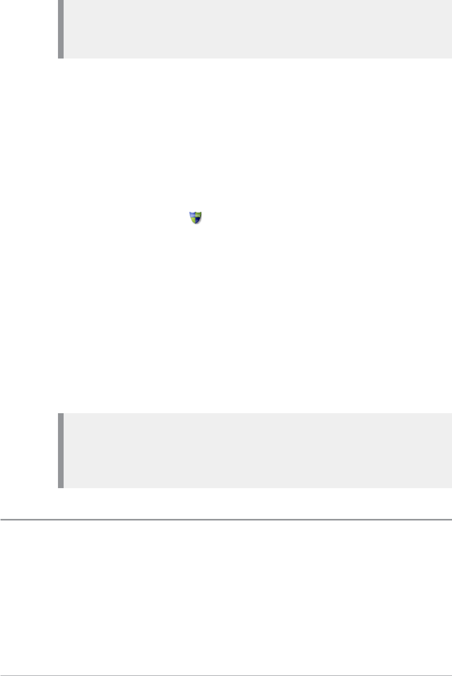
Note: It is not possible to accidentally make a non End-to-End encrypted
call. Every talkgroup or individual subscriber that can be exempt from
End-to-End Encryption must be explicitly customised into the radio.
End-to-End Encryption is designed to provide maximum security for voice
and SDS communications, whether operating in Direct Mode or Trunked
Mode, irrespective of the security level provided by the network.
A radio that supports End-to-End Encryption may nevertheless be required
to make calls that are not End-to-End Encrypted. For example, calls to certain
talkgroups and individual subscribers may be customised to be exempt from
End-to-End Encryption. All telephone calls are also not End-to-End
Encrypted.
When dialling, a separate Secure Comms icon is displayed in the dial box if
the call or SDS will be End-to-End encrypted. During voice calls only (not
SDS calls) your radio my allow you to toggle End-to-End Encryption on/off
with a soft key.
When you are in a voice call, the Secure Comms icon indicates whether End-
to-End Encryption is operational. When the radio participates in a call that is
not End-to-End Encrypted, a periodic non intrusive audible alert is generated
(if customised).
When you receive an SDS (text) message or picture messages, if you see the
Secure Comms icon in the message details that the message was End-to-End
Encrypted.
Note: If the message ‘Security Check Fail’ is displayed while making or
receiving calls, it indicates that the radio has not been customised
properly. In such cases, please contact technical support in your
organisation.
Zeroising
Radios that support End-to-End Encryption are loaded with sensitive
cryptographic keys. To avoid a potential security compromise, you may be
able to delete (zeroise) these cryptographic keys if permitted by your
operational procedures.
134 SC20 series – 04/2016

Please refer to your Security Officer for details on how to zeroise your radio
as well as related operational procedures.
User Guide 135
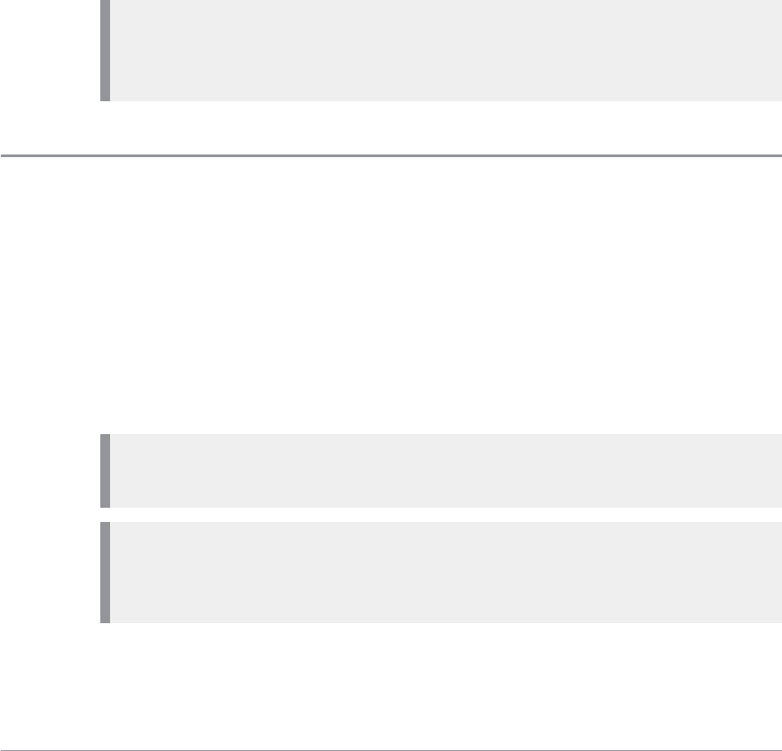
Asset management
Handsets, consoles, radios and accessories are assets that need to be
effectively managed throughout their life cycle. In some organisations it is a
requirement to track assets and this can be done by labelling them.
Another method of tracking an asset is to use the RFID tag to track radios and
associated resources (persons and vehicles).
Asset management refers to the periodic maintenance of your radios.
Maintenance includes software upgrades and reprogramming of the radio to
ensure that it continues to meet your requirements.
Note: During programming the radio uploads information, such as the
State of Health of the battery which can also assist with auditing and end-
of-life strategies.
Labelling
The simplest form of asset management is to attach labels to your radios and
batteries. Self adhesive labels (those with an adhesive backing) are
recommended as they are easy to apply and commercially available, such as
3M™ Thermal Transfer Polyester label material 7815.
Your radio and Sepura battery provide an area for attaching an asset label.
Placing the label here will prevent it interfering with the way the product is
used.
Caution: Do not use solvent based adhesives. Always check the adhesive
used with the self-adhesives label.
Caution: Do not engrave any part of the radio. Engraving the radio's
casing may affect the compliance ratings and may invalidate the product
warranty.
136 SC20 series – 04/2016

Caution: Do not use paint, correction fluid or other forms of liquid or
aerosol to write or mark the radio or an accessory. Chemicals may affect
the radio's casing and invalidate the compliance ratings and product
warranty.
Place a label on the back of the radio in the label ID area above the carrying
aid attachment point as shown.
Alternatively, a label can be placed on the Card Compartment door recess,
but it must not interfere with the fitting of the battery or the opening/closing
of the card compartment.
Place a label on the battery in the Label IDarea.
RFID tag
Radio Frequency Identification (RFID) tags can be useful for asset tracking,
allowing you to automate audit tracking of pool radios, tracking radios in/out
of service centres and stock tracking. It is also useful for pairing pool radios
with resources (persons and vehicles) and facilitating the rights of access to
secure areas.
These tags allow devices to be tracked through a communications network -
when the tag with a unique ID is moved within the proximity of a RFID
read/write unit, it reads the stored data or writes data to the tag.
User Guide 137
Your radio has an integrated 'passive' RFID tag fitted, it is able to operate in
the presence of a RFID read/write unit, even when the radio is powered
down or has its battery removed. RFID tags operate at various frequencies—
the tag in your radio is preprogrammed to operate at a frequency of 125 kHz.
The range of operation is dependent on the RFID read/write unit.
Note: Read the Sepura document RFID in STP9000 Series Information Sheet
(Document no. MOD-12-1459) for more information and technical
specifications of the tag and read/write unit requirements.
How the RFID tag works in your radio
The RFID tag fitted into the back of the radio, its exact position is marked by
the embossed RFID logo. Hold the radio with the embossed RFIDtag within
range of the RFID read/write unit. The RFID tag operates in the presence of
the RFID read/write unit even when the radio is powered off or has the
battery removed.
Note: The distance between the RFID tag and read/write unit may differ
depending on the type of read/write unit being used. Always read the
instructions supplied with the RFIDReader on how to operate it.
Customising your radio
Your radio has a large number of parameters that can be customised using
the programming software tool, Radio Manager 2. These parameters are
grouped into a series of templates that can be easily modified to suit the end
user's preferences. A complete set of parameters for your radio is called a
customisation.
Radios can be customised either in bulk, by fitting them into a Sepura
programming pod which can accommodate 4 or 8 radios at a time, or
individually by directly connecting them to a computer running Radio
Manager 2 software using a Sepura Data/Programming Cable.
Note: Your radio cannot be programmed when Connector Protector on
page 106 is enabled.
138 SC20 series – 04/2016
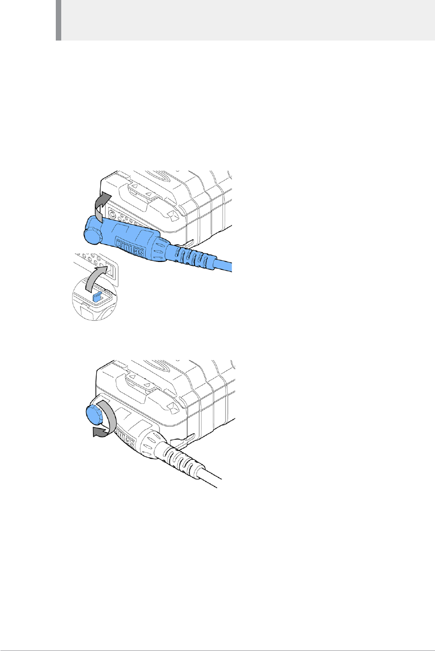
Note: Your radio must be powered on and have sufficient battery charge
for the duration of the customisation process.
To program a single radio
A data/programming cable, with either an RS232 (D-type) connector or a USB
connector, is available from Sepura for customising a single radio.
1. Connect the USBprogramming cable to the computer.
2. Connect the cable to the radio by inserting the hook on the connector into
the slot as shown.
3. Secure the cable in position. Do not over tighten.
4. When programming is complete disconnect the cable from the radio.
User Guide 139

Accessories
There are various accessories available for your radio from fastening clips for
attaching the radio to clothing, to headsets and microphones that provide
hands-free operation. Only use Sepura approved accessories with your radio.
Sepura products have been tested to meet strict guidelines for personal safety
and operational conditions. The use of non-approved accessories may damage
the product, will result in the non-compliance with regulatory requirements,
compromise the product safety ratings, and will invalidate the product
warranty.
Caution: Some accessories may not work in close proximity of a TETRA
radio. When using USB and BT accessories, it is recommended that they
are worn on the opposite side of the body to the radio. It is the
responsibility of the service provider to ensure that appropriate EMC
testing has been conducted on accessories.
When your radio powers on and when you attach an accessory during
operation, your radio performs an authenticity check on any attached
accessories including the battery. If the accessory is not authenticated, a
message appears and the accessory should be removed.
Your radio has two connectors for attaching accessories. The rugged
accessory connector (sRAC) on the side of the radio is used for attaching
accessories such as a remote speaker microphone (RSM), headsets and
earpieces. At the bottom of the radio is the digital audio connector (sDAC)
that is used for attaching car kits, data accessories and chargers. It is also used
for programming the radio.
Caution: When using an RSM with antenna, it should be held a
minimum distance of 25 mm from the mouth.
Always refit the cover to the sRAC when an accessory is not in use.
You do not need to power down the radio before fitting or removing an
accessory.
140 SC20 series – 04/2016
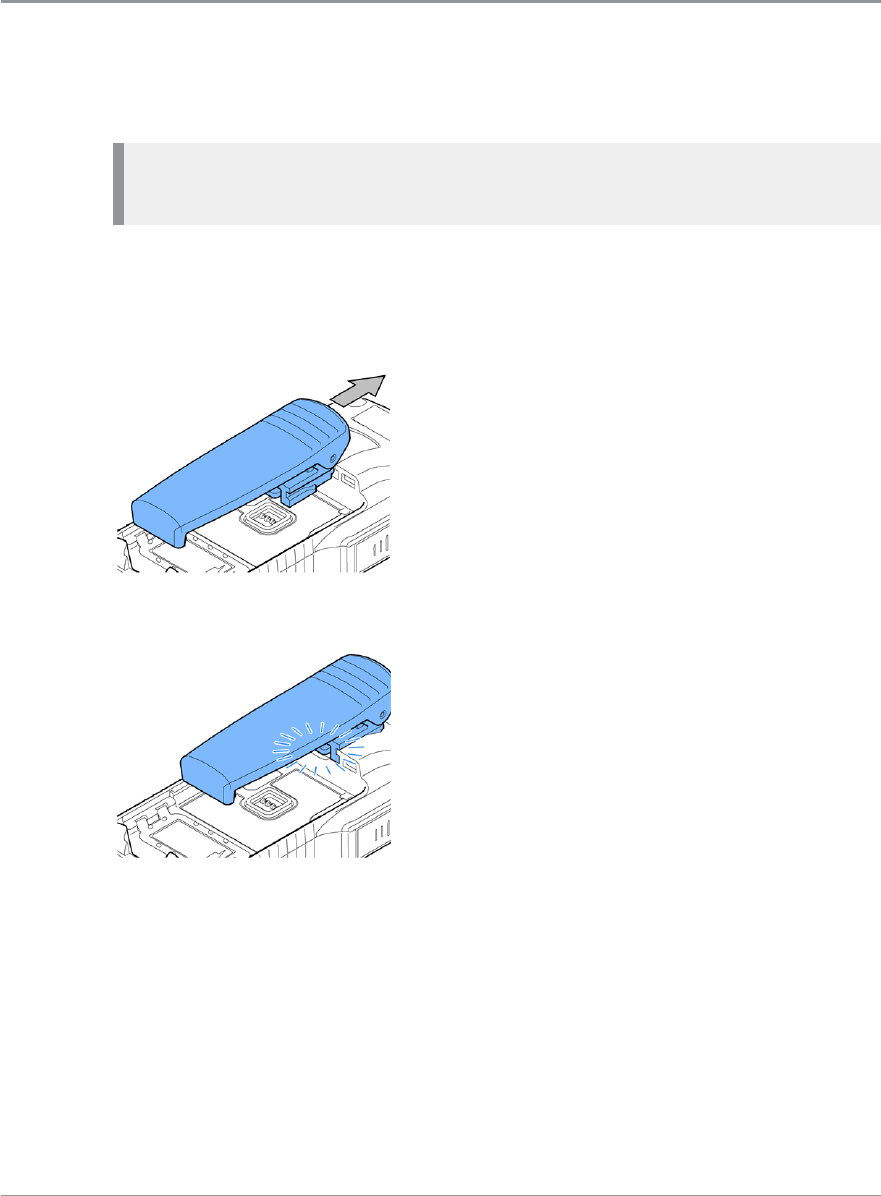
Always read the instructions supplied with the accessory for operating
instructions and safety information.
Belt clip
The belt clip is used to attach your radio to clothing or to a belt. The clip is
fitted to the carrying aid attachment recess on the back of your radio.
Caution: Damage to product. Always remove the battery before fitting or
removing the clip.
Fit the belt clip
1. Remove the battery.
2. Slide the stud into the carrying aid attachment recess.
3. Slide until it clicks into place.
Remove the belt clip
1. Remove the battery.
2. Lift the clip.
User Guide 141
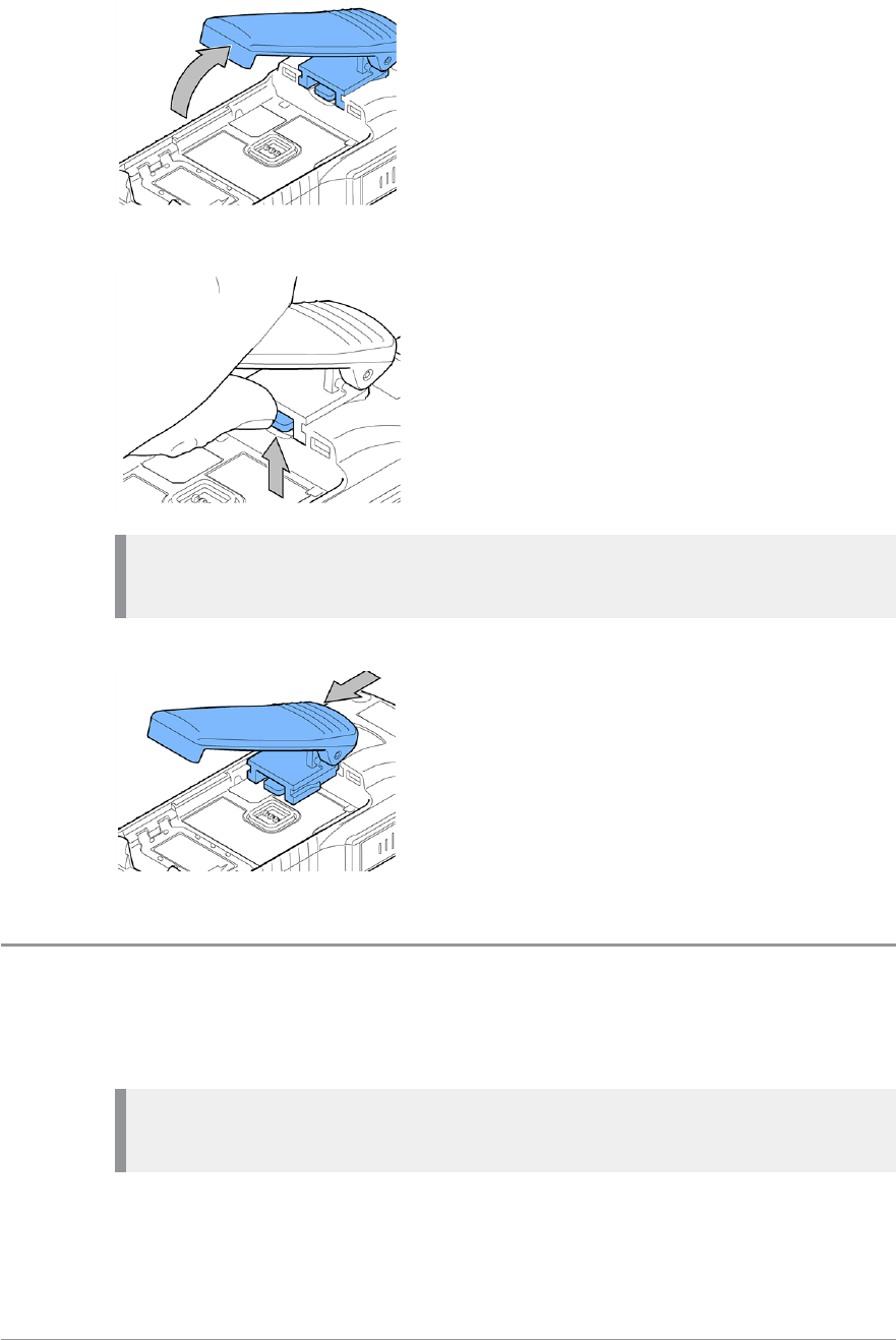
3. Use your thumb to compress the spring and release the clip.
Caution: Failure to compress the spring sufficiently to remove the clip,
will result in damage to your radio or the clip.
4. Slide the clip out of the carrying aid attachment recess.
Klick fast stud
The Klick fast stud is used to attach your radio to clothing. The stud is fitted
to the carrying aid attachment recess on the back of your radio.
Caution: Damage to product. Always remove the battery before fitting or
removing the stud.
142 SC20 series – 04/2016
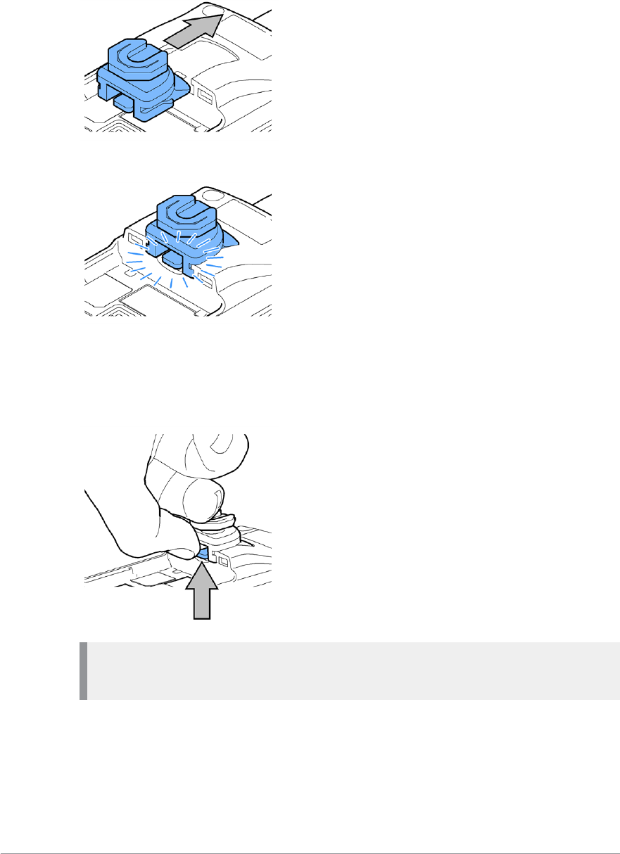
Fit the stud
1. Remove the battery.
2. Slide the stud into the carrying aid attachment recess.
3. Slide until it clicks into place.
Remove the stud
1. Remove the battery.
2. Lift the spring.
Caution: Failure to compress the spring sufficiently to remove the stud,
will result in damage to your radio or the stud.
3. Slide the stud out of the carrying aid attachment recess.
User Guide 143
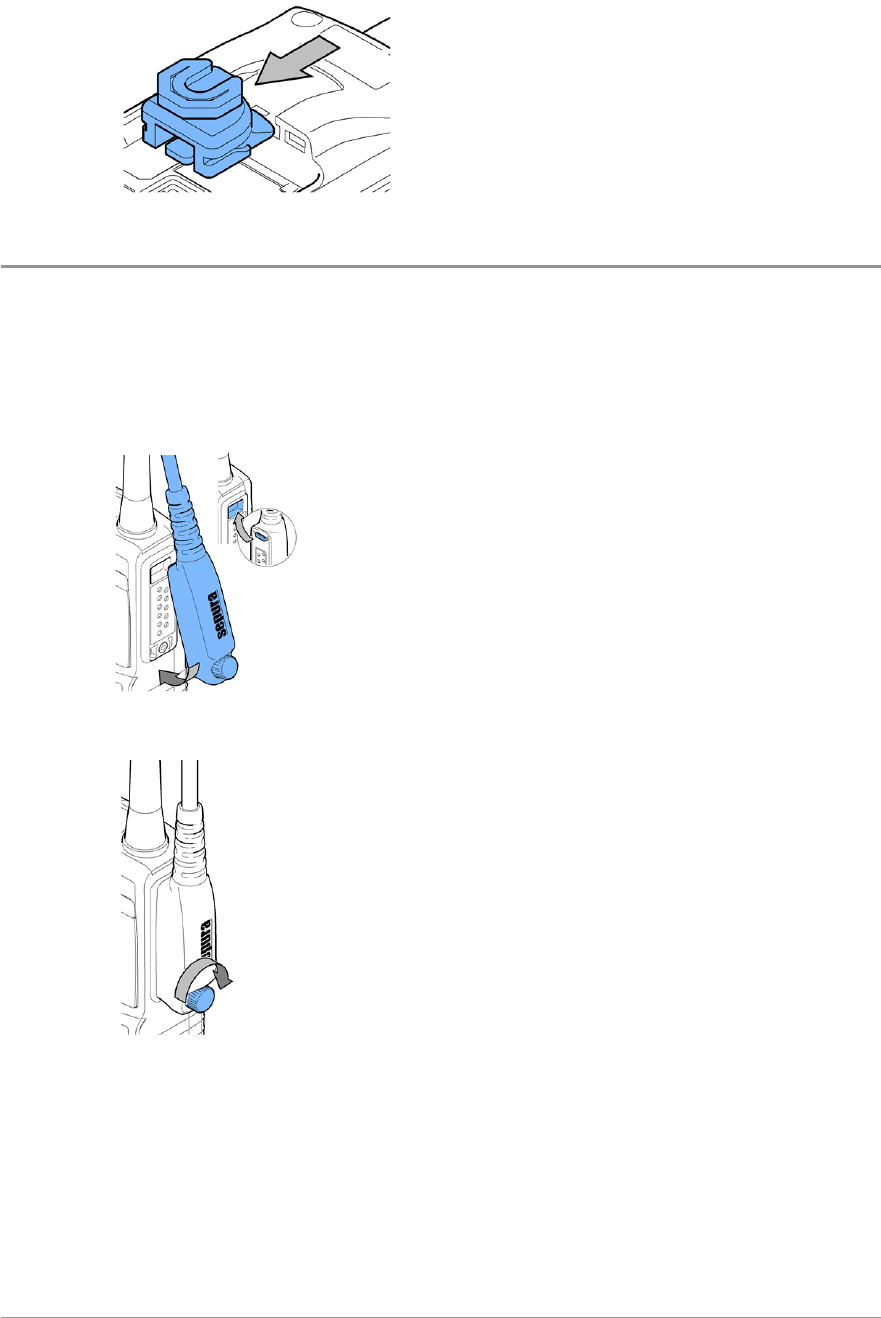
Fit an accessory
Fit an accessory to the sRAC
1. Remove the cover from the sRAC connector.
2. Insert the hook on the accessory connector into the slot as shown.
3. Secure the accessory by rotating the screw clockwise.
Fit an accessory to the sDAC
1. Connect the cable to the radio by inserting the hook on the connector into
the slot as shown
144 SC20 series – 04/2016
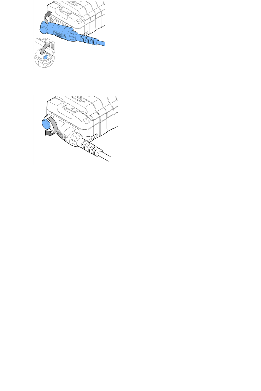
2. Secure the accessory in position by rotating the screw clockwise. Do not
over tighten.
User Guide 145

GLOSSARY
The following conventions are used in
this glossary:
(S) Sepura product term
(T) TETRA term
sf Short form (abbreviation or
acronym).
Alarm Call
A call enabling a user to request assistance in case of an
emergency scenario threatening life and physical
condition. Alarm Calls have the highest priority on the
network. This call can trigger a sequence of customisable
events which may include ‘live microphone’ (allowing the
user to broadcast the situation to other radio users within
the talkgroup and the Dispatcher), an outgoing speech
call, position reports and status messages. (Alarm Calls
are sometimes loosely referred to as Emergency Calls.)
(T)
Connector Protection
A Sepura feature that allows a radio to be used in a salt
water environment or an area with high salt laden
humidity (for example sea mist/fog) without potential risk
of corrosion to the connector. (S)
context key
User-programmable key on a Sepura radio that can be
customised to provide a shortcut to a menu option, such
as the Contacts list or Talkgroups. Radios may typically
have left, centre and right context keys. (S)
Direct Mode Operation (DMO)
The facility for TETRA radios to communicate directly
with each other without using the TETRA infrastructure.
Also referred to as half duplex operation (one user talks
at a time). (T)
DMO gateway / Direct Mode Operation
gateway
A device that allows users working in Direct Mode
Operation to communicate with users in Trunked Mode.
This is often used to extend the working range of a radio.
(T)
DMO repeater / Direct Mode Operation
repeater
A radio acting as a repeater provides a service to other
radio users. It extends the range and enhances the
reliability of Direct Mode communication compared with
basic direct communication between the radios. (T)
End-to-End Encryption (E2EE)
Encryption of the total communication link (from one end
to the other) without intermediate decryption, required for
maximum security.
full duplex
A channel providing simultaneous transmission in both
directions, allowing both parties to speak and listen at the
same time. This is achieved by using two timeslots on a
single TETRA carrier frequency to establish
communication back and forth. The most common use of
this system is in telephone systems around the world.
Push-To-Talk switches are not needed during this
method of communication.
gateway
A device which interfaces the TETRA network with other
private or public telecommunications networks, such as
PSTN and ISDN. See also DMO gateway and GMO. (T)
group call
A call made by one radio user to other users within a
nominated talkgroup. Groups are set up on the radio (also
known as talkgroups) that contain other radio users either
performing a similar role or who are within a distinct
location. This type of call is initiated when the user
presses the PTTbutton on the radio. Only one person can
talk at any time during these calls. (T)
Group Short Subscriber Identity (GSSI)
Short form TETRA group identification number. sf. (T)
half duplex
A system that only allows the transmission of a radio
signal in either direction, but not simultaneously.
Meaning, only one person can speak and one (or more)
people can listen at any given time. The majority of two-
way radios only provide half duplex communication.
146 SC20 series – 04/2016

User Guide 147
haptic, haptics
Haptic technology, haptics, or kinesthetic communication,
is tactile feedback technology which recreates the sense of
touch by applying forces, vibrations, or motions to the
user.
ISSI
Individual Short Subscriber Identity. sf. (T)
keypad lock
a) A function on a device, such as a mobile phone or
computer, that prevents a user accidentally activating
functions using the keypad or to prevent access to the
functions for security reasons.
Lone Worker
A operating function of a radio, associated with a user
profile, that allows a user working alone to indicate that
they are safe. When the user selects the Lone Worker
profile, the radio will periodically emit an audible alert.
Each time the user hears the alert he or she must press a
key on the keypad to prevent an alert being triggered. If
no key is pressed within a given time, the radio will send
an Emergency Status message will to a customised
location, for example to the Dispatcher. It can be
configured to send an emergency call or GPS co-
ordinates if an emergency situation is detected. See also
User Profiles.
Mode key
A key on a Sepura radio or mobile that activates various
functions when pressed or when pressed together with
the Navi-knob or Navi-keys. (S)
navigation keys
Four arrow keys (Left, Right, Up And Down ) on a
Sepura radio that allows users to choose menu options
and navigate through the menus. The keys are located
above the keypad. (S)
Navi-knob
A continuous rotating knob on a Sepura TETRA radio that
allows the user to change talkgroups, select status
messages, as well as controlling the speaker volume. (S)
keypad
A set of buttons arranged in a block or pad that have
either digits, symbols or alphabetical characters on, or a
combination of all of these. Do not use key mat,
keyboard, or alphanumeric keypad.
PABX
Public Automatic Branch eXchange. sf.
picture message
A small JPEG image file with an accompanying text
message sent to recipients over the TETRA Air Interface.
(S)
point-to-point call
A half duplex call made to a contact on the network using
the PTT button. Unlike a group call, a point-to-point call is
a private call to an individual.
PSTN
Public Switched Telephone Network. sf. (T)
PTTbutton
The button, usually on the side of the radio, pressed to
initiate a group call. The button is released to listen to any
response from other radio users.
Quick Call
A special individual call configured on a soft key to
request help or information from a pre-configured
individual or talkgroup destination in a non-emergency
situation. (S)
repeater
A device that is installed at a fixed location and whose
sole purpose is to receive a signal and then retransmit the
same signal at a higher strength. Repeaters are used by
institutions such as police departments and hospitals to
transmit signals over a longer distance than the two-way
radio was previously capable of. Installing a repeater
commonly used to eliminate a dead spot in a building or
town.
screen saver
An animation or image which replaces an unchanging
computer display after a period of inactivity.
SDS
Short data services (SDS) are TETRA transport services
for the transmission of data. Messages can be sent and
received by TETRA radios, dispatchers, and external
applications. The parties are identified by 24-bit integer
Short Subscriber Identities (see "S"). sf.

short data services (SDS)
Text messages that can be sent or received on a TETRA
radio.
soft key
A programmable key on a Sepura radio that can be
customised as a shortcut to a function, for example a
context key on the radio that can be customised as a
shortcut to the Contacts list. On some radios, the
Select/Send key and the Cancel/Home key, along with all
12 keys of the radio keypad (1 – 9, *, 0, #,), left- and right-
context keys, and the Emergency Key are programmable
soft keys. (S)
Smart Call
On Sepura radios, a Smart Call is a call to an address
other than the selected talkgroup. (S)
status message
Words or concise phrases selected from a pre-determined
list that is resident in the terminal, which are transmitted
as a simple code reference, and then de-coded by the
receiving device and displayed as the word message, e.g.
"At the scene".
talkgroup
A pre-defined group of users on one frequency band. (T)
telephone call
Use this term when referring to the user making a
telephone type call, where the user holds the radio similar
to that when holding a telephone handset or mobile
phone. Do not use the term full duplex call in user
documents. See also private telephone call, and group
call.
Transmit Inhibit mode
An operational mode for use in RF sensitive areas, that
allows the radio to continue operating without
transmitting. When Transmit Inhibit is activated and
deactivated, a status message is sent confirming the
operational state of the terminal.
Trunked Mode Operation (TMO)
Radios operating over the TETRA network.
tri-colour LED
An LED with three colours that is used on a Sepura radio
and mobile transceiver to alert the user to a change of
state such as the radio operating in transmit inhibit mode.
Sometimes called the Status Indicator. (S)
UDSL
User Defined Scan List. sf.
User Defined Scan List (UDSL)
Pre-programmed (optionally user editable) list of scanned
groups.
user profile
User profiles are pre-set combinations of alerts and
settings on a Sepura radio designed to match the user's
circumstances or environment. If the User Profiles feature
has been customised it allows you to switch easily
between user profiles. When a user profile is selected, an
icon is displayed on the status line at the top right of the
display to indicate which user profile is active. (S)
WAP
Wireless Application Protocol. sf.
whisper mode
A customisable feature on a Sepura radio which adjusts
the sensitivity of the microphone to allow the user to
whisper verbal communications during covert operations.
(S)
148 SC20 series – 04/2016

Sepura plc
9000 Cambridge Research Park
Beach Drive
Waterbeach
Cambridge
CB25 9TL
United Kingdom sepura.com