Shinko Electric Co 199909010001 Communication Modem Controller User Manual ROHV Operation Manual
Shinko Electric Co Ltd Communication Modem Controller ROHV Operation Manual
UserManual.wiki
>
Shinko Electric Co
>
199909010001 User Manual
>
ROHV Operation Manual
Contents
1.
OHVC Operation Manual
2.
ROHV Operation Manual
3.
OHT Teaching Manual
4.
System Operation Manual
5.
Power Supply Operation Manual
6.
Power Supply Operation Manual Fig1
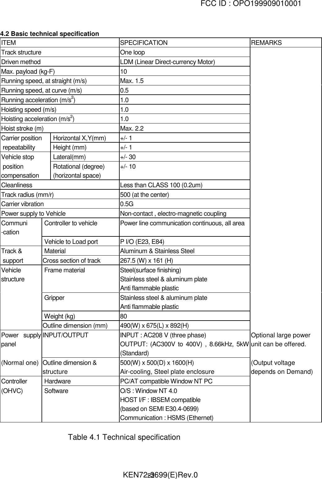
ROHV Operation Manual
Navigation menu
Upload a User Manual
Namespaces
Wiki Guide
HTML
PDF
Info
Views
User Manual
Discussion / Help
Navigation
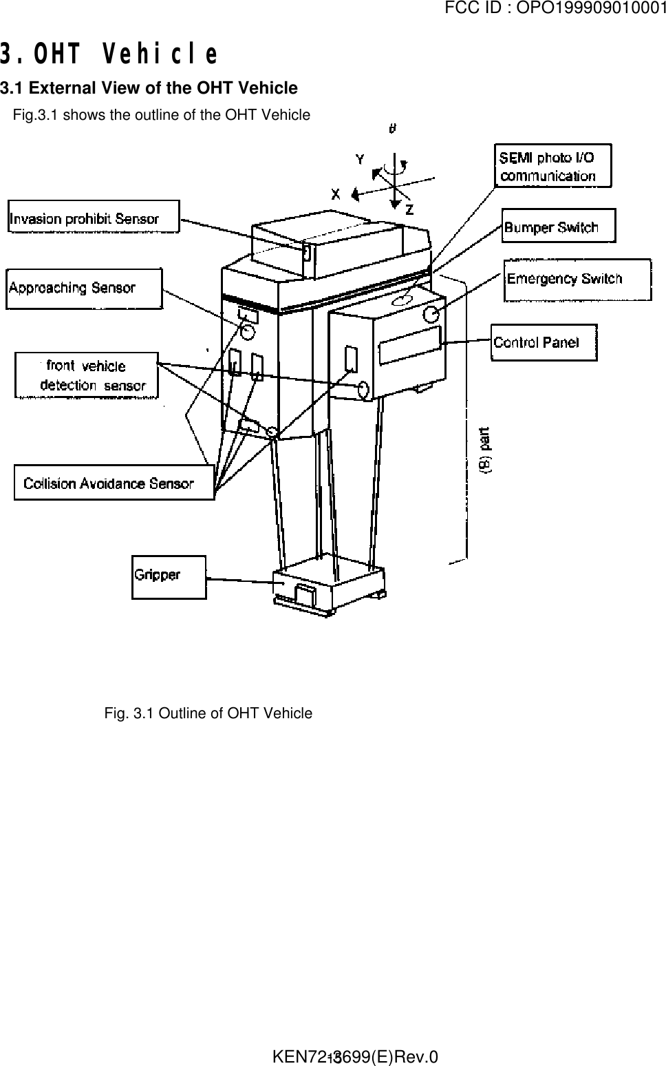
![FCC ID : OPO199909010001 KEN72-3699(E)Rev.05 Safety precautions(1) General Prior to using this product, make sure the “Safety Precautions”, Maintenance InstructionManual and other attached documents shall be well read and understood for appropriateapplication. Engage specialists in electrical works. Don’t improve the product by yourselves. Be sufficiently proficient with the equipment, the relevant safety knowledge and theprecautions prior to using this product.In the content of this “Safety Precautions”, items which need to be cautions of out shallbe classified into “Danger” and “Warning”.(2) Definitions of Danger and Warning[Note 1] Medium degree of injuries or light injuries refers to injuries, e.g., burns and electric shock, which do not require hospitalization of or prolonged hospital visit by the victims. As material losses refers to expanded losses pertaining tothe damage of property and equipment.Note that, depending on the situation, the events described under “Warning” may also resultin severe outcome. In either case, make sure that the advice is followed.After reading, make sure this information shall be kept at places where it can always be readby users.](https://usermanual.wiki/Shinko-Electric-Co/199909010001.ROHV-Operation-Manual/User-Guide-59591-Page-5.png)