TENDA TECHNOLOGY DH301 Wireless N300 ADSL2+ High Power Modem Router User Manual
SHENZHEN TENDA TECHNOLOGY CO., LTD. Wireless N300 ADSL2+ High Power Modem Router
Contents
- 1. Users Manual Part I
- 2. User Manual Part II
User Manual Part II
Wireless N300 ADSL2+ High Power Modem Router
117
4.2.13 Storage Service
This section helps you to use USB Storage devices in your modem router, including the following parts:
• User Account: You can control the LAN users’ accessing to the USB storage device information, namely, some of
them can access the USB device info but others cannot.
• Storage Device Info: When you plug the USB storage device into the USB interface of your modem router, the router
can recognize that’s the USB storage device and then read the storage device’s information.
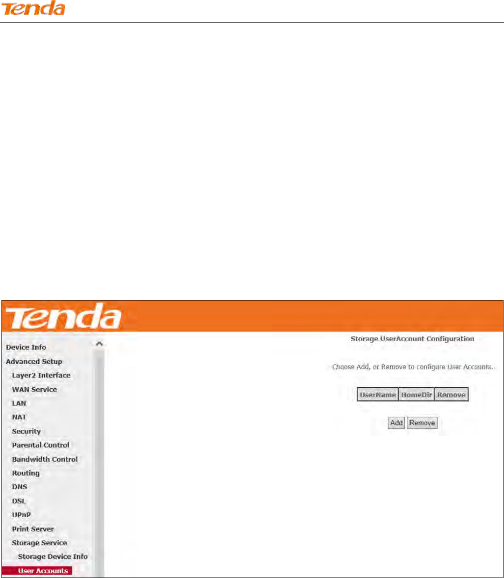
1) User Account
Before you share your USB storage on the internet, you need to add a storage user account. And only the users on the
user account list can visit the USB storage device plugged in the modem router. Thus, before you access the USB storage
device, you need to set the user account information.
To add a new account:
Click Add to enter the user account configuration page.
Wireless N300 ADSL2+ High Power Modem Router
118
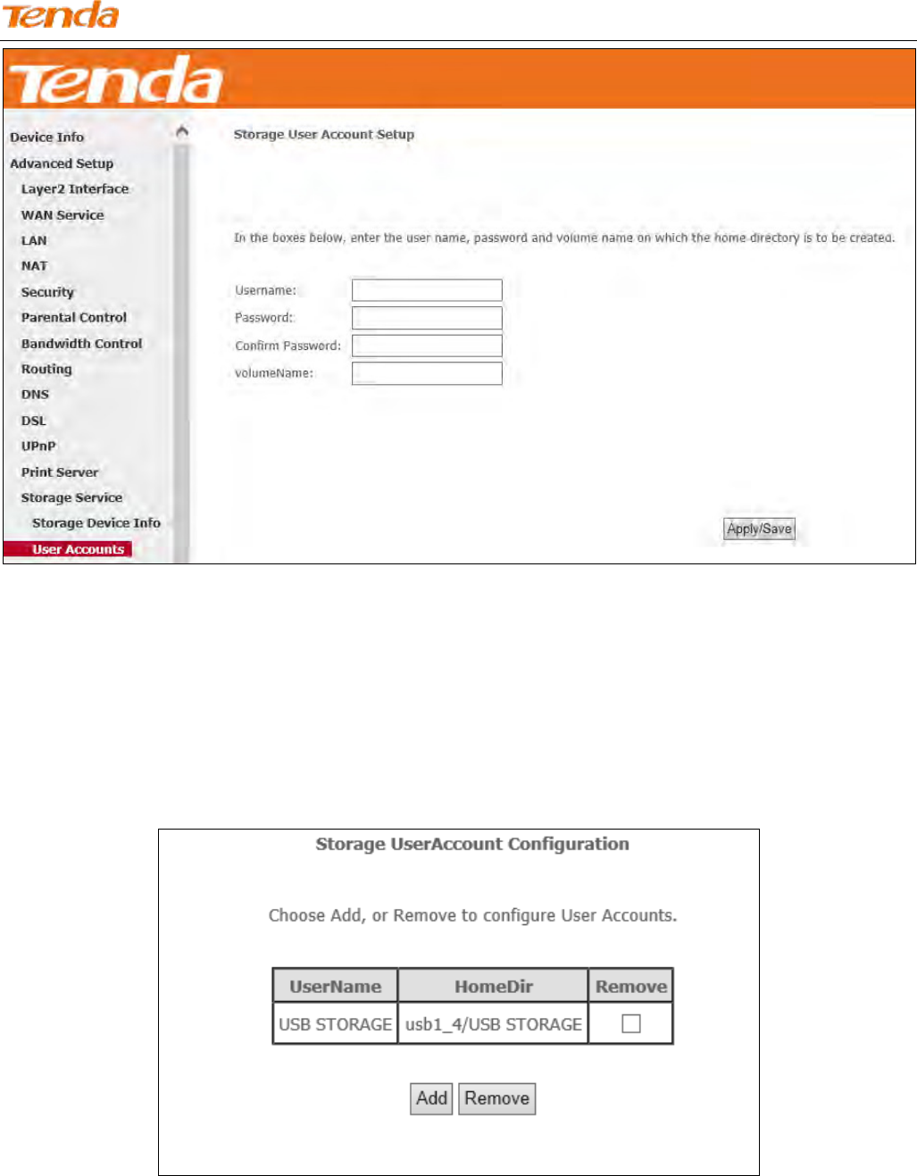
Name your USB storage account.
Specify a password to secure your USB storage account.
Enter your password again for a confirmation.
Enter the volume name of the USB storage, which is displayed in the Storage Device Info page.
Click Apply/Save to save your configurations.
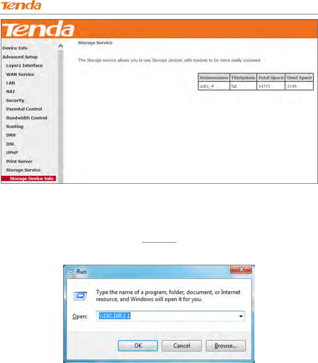
1) Storage Device Info
Your modem router can automatically recognize the USB storage device and the Storage Device Info screen will show
the information such as the volumename, file system, total space, and used space.
Wireless N300 ADSL2+ High Power Modem Router
119
After your modem router recognizes the USB storage device, follow guidelines below for visiting the storage info via the
computer on the LAN. Here takes Windows 7 as an example to explain the guidelines which are similar in other
operation systems.
Press Win+R keys. On the Run window, input \\192.168.1.1 (\\+ LAN IP address of the router), and then click
OK.
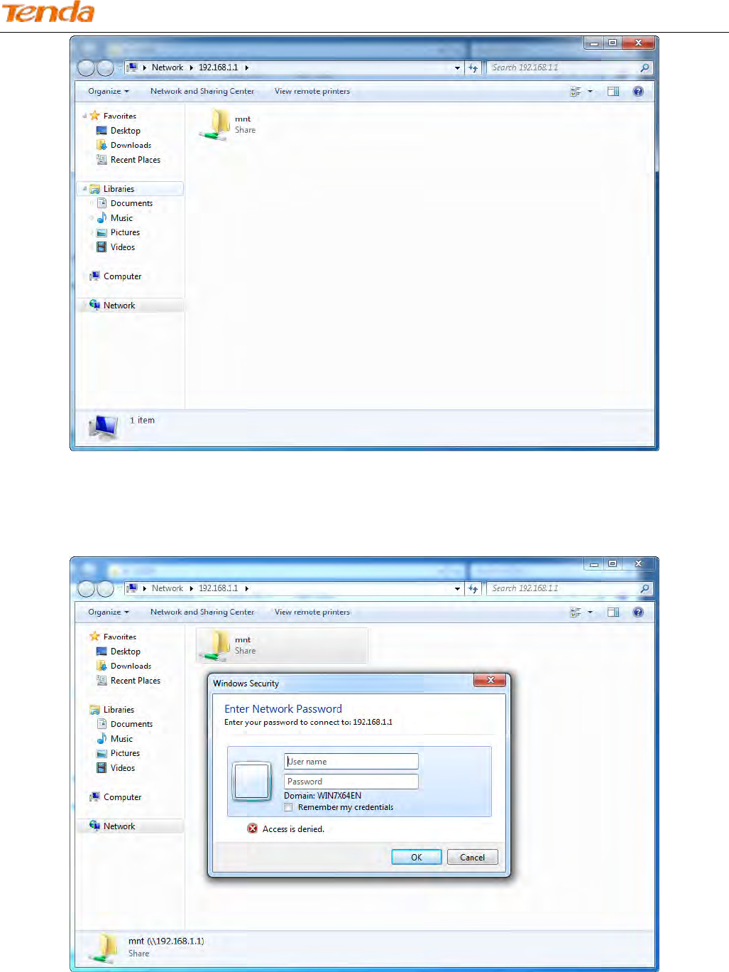
Double click the USB storage device icon (“mnt”).
Wireless N300 ADSL2+ High Power Modem Router
120
Account authentication: Enter your user account name and password which were configured in User Account part
in the corresponding box, and click OK.
4.2.14 Interface Grouping
Interface Grouping supports multiple ports to PVC and bridging groups. Each group will perform as an independent
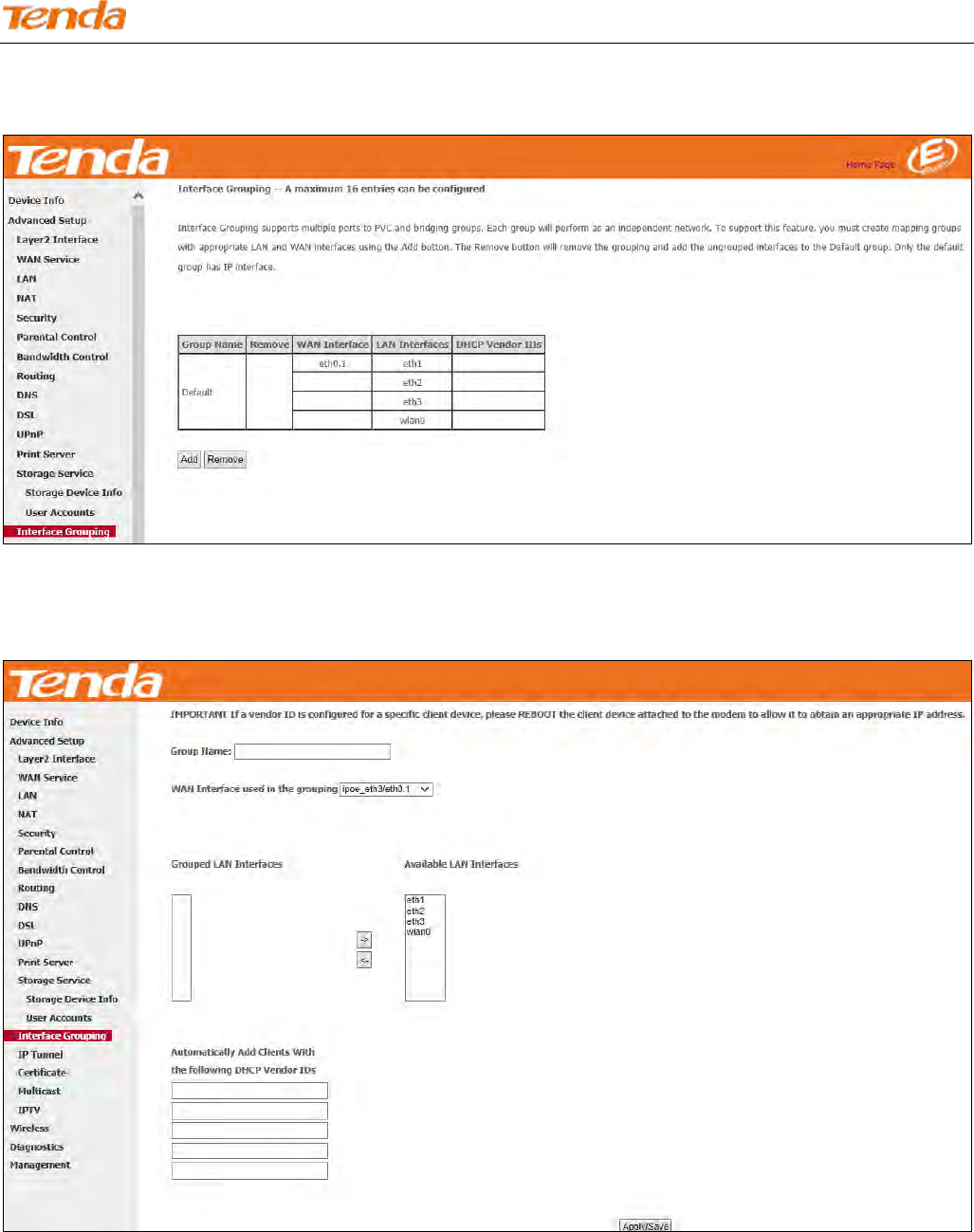
Wireless N300 ADSL2+ High Power Modem Router
121
network. Only the default group has IP interface.
Click Advanced Setup > Interface Grouping to enter the following figure.
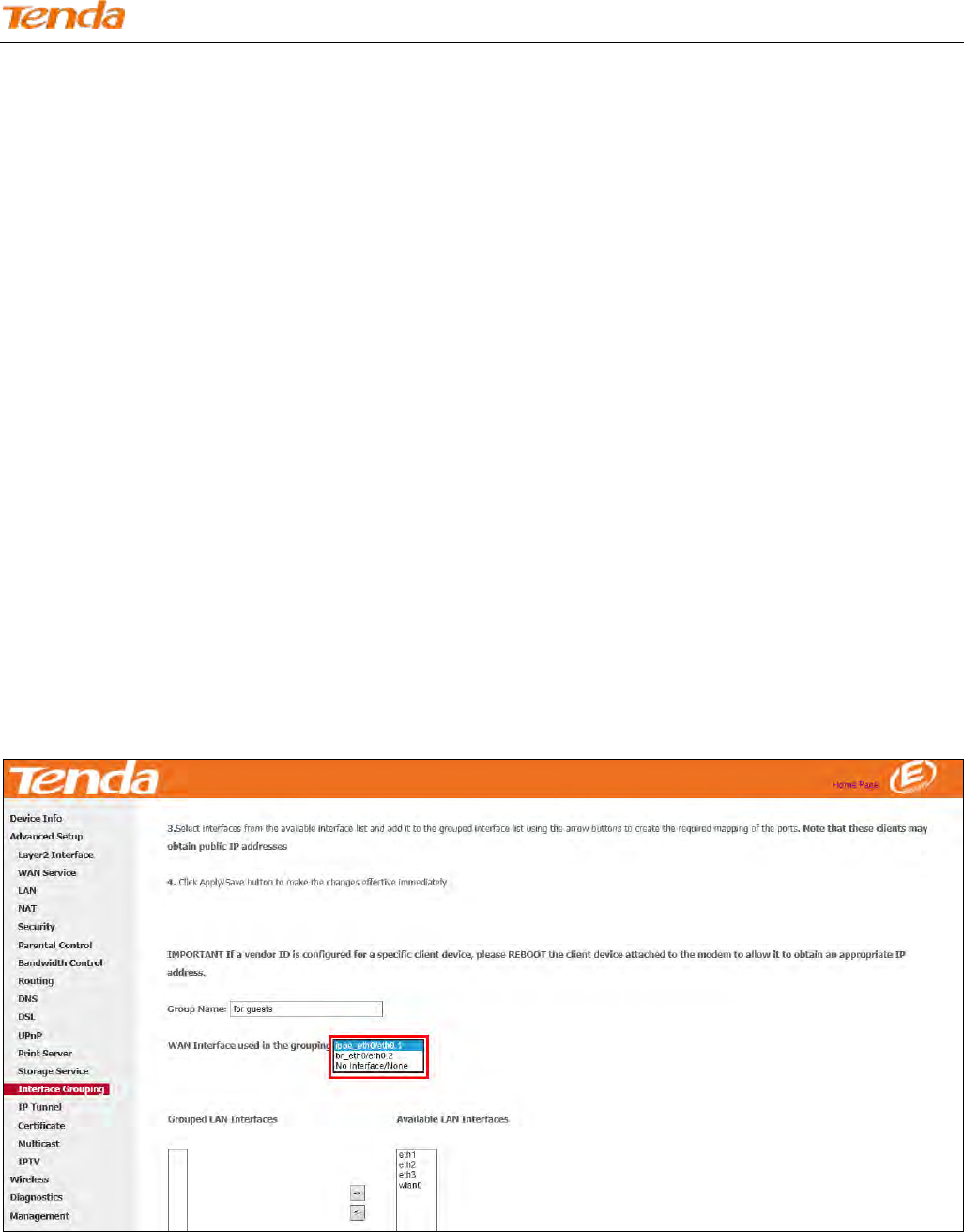
Click Add to enter the screen below.
Group Name: The name of a configured rule.
WAN Interface used in the grouping: WAN connection to which the interface grouping rules apply.
Available LAN Interfaces: LAN interfaces that can be used for interface grouping.
Grouped LAN Interfaces: LAN interfaces that use specified WAN interface.
Wireless N300 ADSL2+ High Power Modem Router
122
To create a new interface group:
Enter the Group name which should be unique.
Select the WAN interface that’s shared by the LAN interfaces in the interface group.
Select interfaces that will be connected to the specified WAN you will use. Note that these clients may obtain public
IP addresses.
Click Apply/Save button to make the changes effective immediately.
If you want to bypass NAT via the router’s interface and obtain the public IP address automatically, you need to add the
DHCP vendor ID in the Automatically Add Clients with the following DHCP Vendor IDs section. After the ID takes
effect, your router will automatically detect the DHCP request from computers on the LAN, and it will forward the
DHCP vendor ID and the corresponding DHCP request to the WAN interface used in the interface rules.
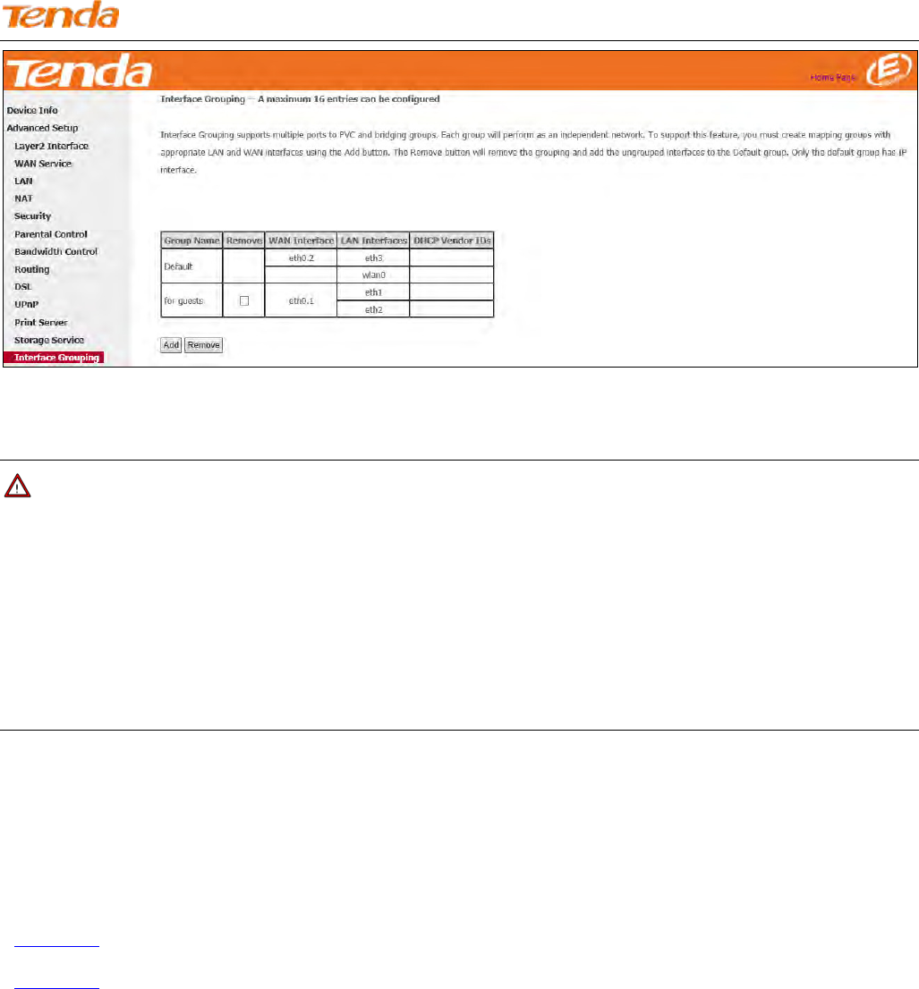
Application:
You have established two WAN service ports: IPoE and Bridge port. Ipoe_eth0/eth1 is used for home users access;
br_eth0/eht0.2 used for guests to access the Internet. You hope that eth1 and eth2 (Interface2 and 3 on the modem router)
can be used for guests to visit the Internet, and meanwhile data of the guest won’t be forwarded to other interfaces.
Configurations are as below in the figure.
Wireless N300 ADSL2+ High Power Modem Router
123
Attention: After successful interface grouping, clients connecting to interface 2 and 3 will obtain IP address different
from 192.168.1.X, but same segment with 192.168.2.1. So clients access the device via 192.168.2.1.
Note
1. After the settings above, you need to reboot the modem router to take the settings into effect.
2. After the settings above, the LAN IP address used by the Default group member is 192.168.1.1, the LAN IP of the
second group member is 192.168.2.1. LAN IPs of the following groups follows the same rule.
3. After you set the IPTV function, the modem router will automatically add one interface group named IPTV, which
should be saved. If it’s deleted, the IPTV function takes no effect.
4.2.15 IP Tunnel
This section explains the following information:
• IPv6inIPv4
• IPv4inIPv6
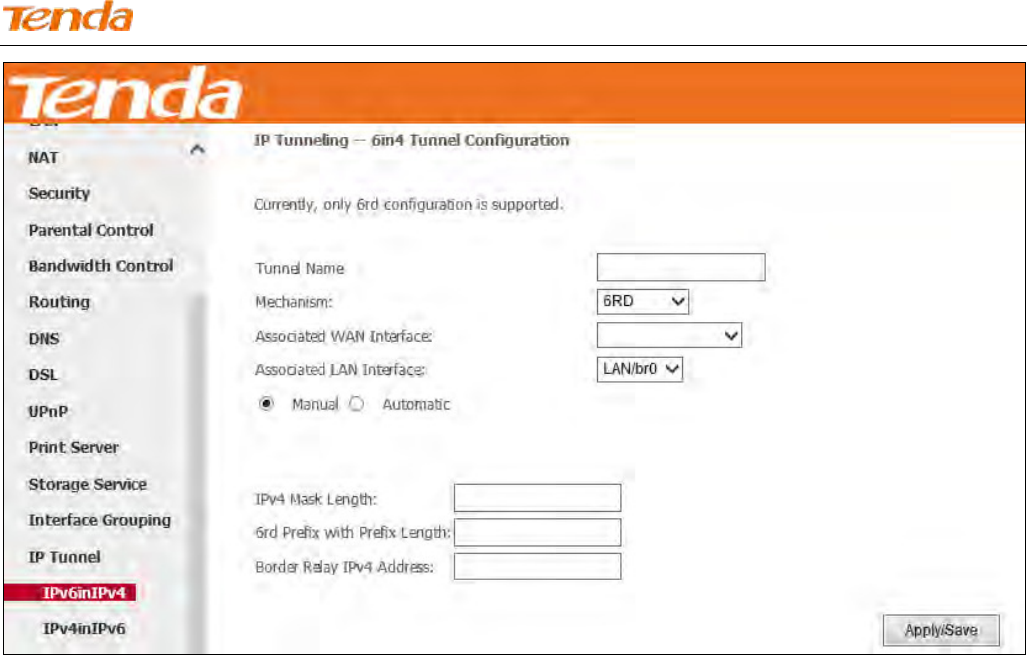
IPv6inIPv4
Click IPv6inIPv4 and Add to enter the following screen:
Wireless N300 ADSL2+ High Power Modem Router
124
Tunnel Name: Specify the name of the tunnel.
Mechanism: Currently, only 6RD configuration is supported.
Associated WAN Interface: Specify the WAN interface of the tunnel.
Associated LAN Interface: Specify the LAN interface of the tunnel.
Manual: If you select Manual, configure the following settings also:
IPv4 Mask Length: Specify the IPv4 Mask Length.
6rd Prefix with Prefix Length: Specify the 6rd Prefix with Prefix Length.
Border Relay IPv4 Address: Specify the Border Relay IPv4 Address.
Automatic: If Automatic is selected, no configurations are required.
Apply/Save: Click to apply and save your settings.
IPv4inIPv6
Click IPv4inIPv6 and Add to enter the following screen:
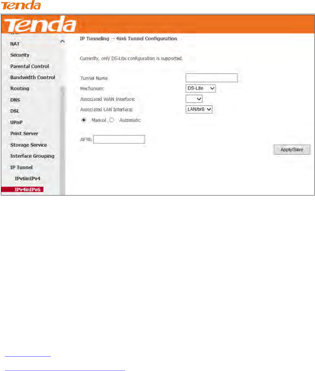
Wireless N300 ADSL2+ High Power Modem Router
125
Tunnel Name: Specify the name of the tunnel.
Mechanism: Currently, only DS-Lite configuration is supported.
Associated WAN Interface: Specify the WAN interface of the tunnel.
Associated LAN Interface: Specify the LAN interface of the tunnel.
Manual: If you select Manual, enter the AFTR information also.
Automatic: If Automatic is selected, no configurations are required.
Apply/Save: Click to apply and save your settings.
4.2.16 Certificate
This section explains the following information:
• Local Certificates
• Trusted CA (Certificate Authority) Certificates
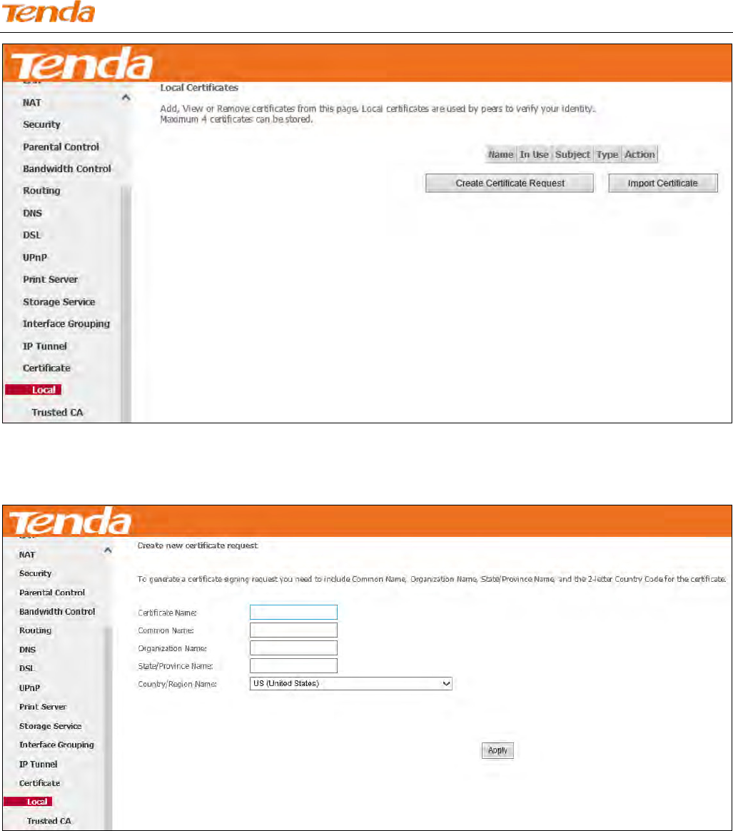
Local Certificates
Here you can add, view or remove certificates. Local certificates are used by peers to verify your identity. Maximum 4
certificates can be stored.
Wireless N300 ADSL2+ High Power Modem Router
126
To generate a certificate signing request:
1) Click the Create Certificate Request button to enter the page below.
2) Specify the Common Name, Organization Name and State/Province Name
3) Select your country or region.
4) Click Apply to apply your settings.
To Import certificate:
Click the Import Certificate button on the local certificates page to enter the page below.
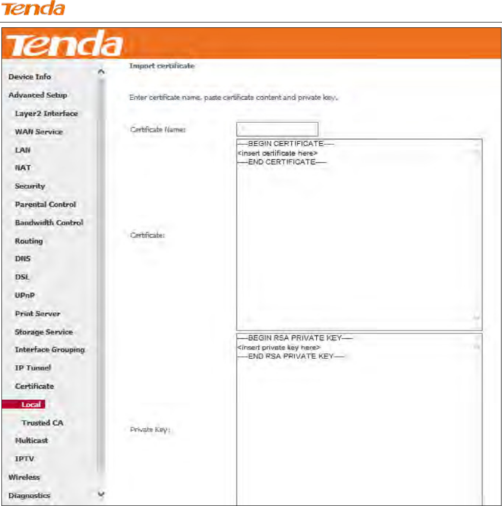
Wireless N300 ADSL2+ High Power Modem Router
127
1) Enter the certificate name.
2) Paste the certificate content and private key.
3) Click Apply to apply your settings.
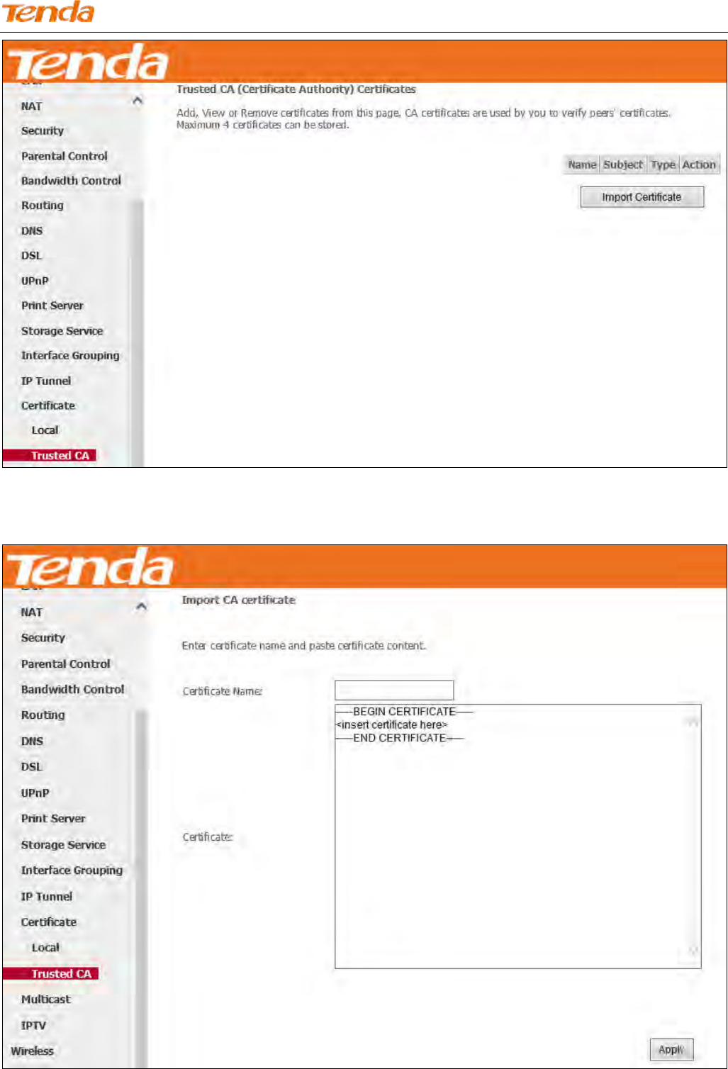
Trusted CA (Certificate Authority) Certificates
Here you can add, view or remove CA certificates. CA certificates are used by you to verify peers' certificates. Maximum
4 certificates can be stored.
Wireless N300 ADSL2+ High Power Modem Router
128
To Import certificate:
1) Click the Import Certificate button to enter the page below.
2) Enter the certificate name.
Wireless N300 ADSL2+ High Power Modem Router
129
3) Paste the certificate content.
4) Click Apply to apply your settings.
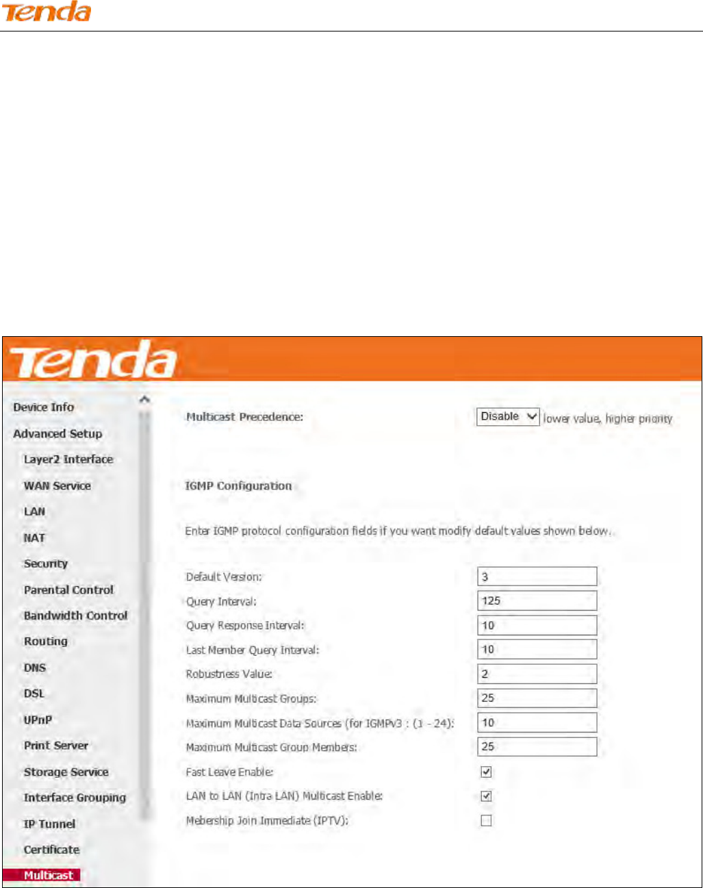
4.2.17 Multicast
Here you can configure the multicast feature.
To configure IGMP for IPv4
Check the LAN to LAN (Intra LAN) Multicast Enable box.
Check the Membership Join Immediate (IPTV) box. This is only required for IPTV.
Keep other options unchanged from factory defaults if you are not an advanced user. This is strongly recommended.
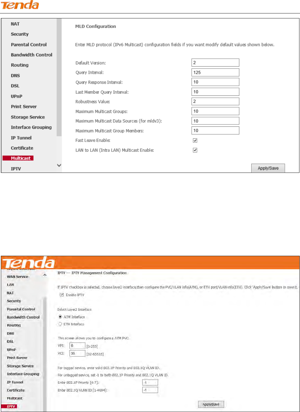
To configure IGMP for IPv6
Check the LAN to LAN (Intra LAN) Multicast Enable box.
Keep other options unchanged from factory defaults if you are not an advanced user. This is strongly recommended.
Wireless N300 ADSL2+ High Power Modem Router
130
4.2.18 IPTV
If you check the Enable IPTV checkbox, you must choose a layer2 interface, and then configure the PVC/VLAN info
(ATM), or ETH port/VLAN info (ETH). Click Apply/Save button to save it.
Enable IPTV: Check/uncheck to enable/disable the IPTV service.
IPTV configuration for Phone Cable Access user:
1) Enable IPTV.
2) Select Layer2 interface: ATM Interface.
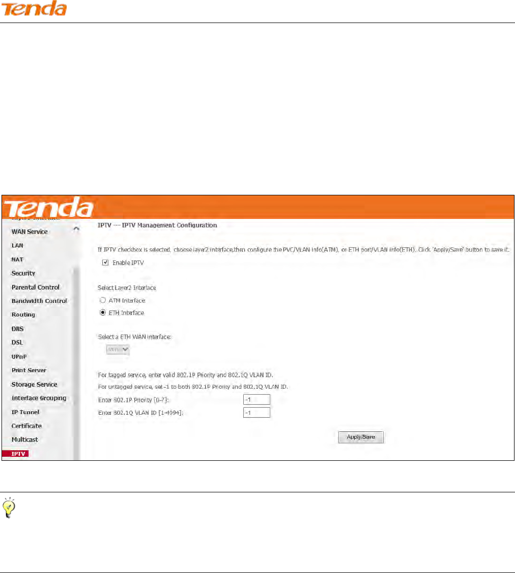
Wireless N300 ADSL2+ High Power Modem Router
131
3) Configure an avaliable VPI/VCI value which should be provided by your ISP.
4) Click Apply/Save.
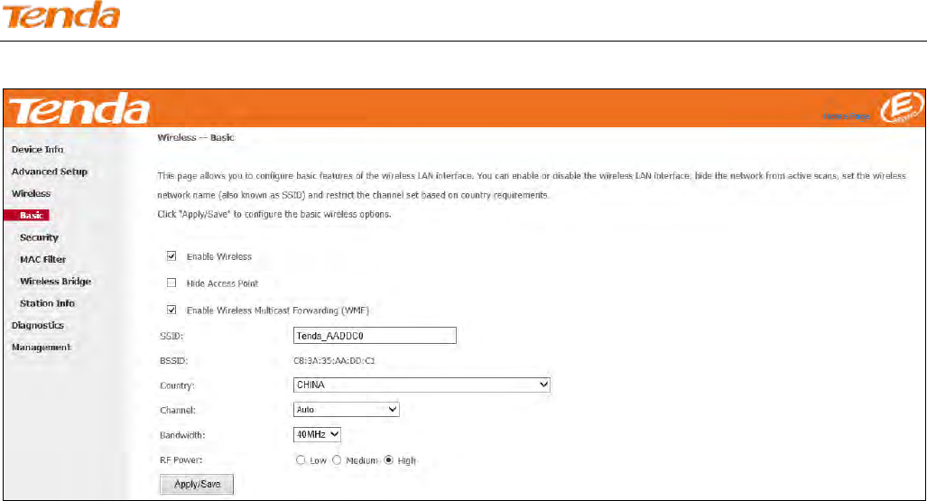
IPTV configuration for Ethernet Cable Access user:
1) Enable IPTV.
2) Select Layer2 Interface: ETH Interface.
3) Click Apply/Save.
After successful IPTV configuration, Port 4 on the back panel of the device can only be an IPTV port.
Tip
For tagged service, enter valid 802.1P Priority and 802.1Q VLAN ID.
For untagged service, set -1 to both 802.1P Priority and 802.1Q VLAN ID.
4.3 Wireless
There are five submenus under the Wireless menu: Basic, Security, MAC Filter, Wireless Bridge and Station Info.
Click any of them, and you will be able to configure the corresponding functions.
4.3.1 Basic
This page allows you to configure basic features of the wireless LAN interface. You can enable or disable the wireless
LAN interface, hide the network from active scans, set the wireless network name (also known as SSID) and restrict the
Wireless N300 ADSL2+ High Power Modem Router
132
channel set based on country requirements.
Enable Wireless: Check/uncheck to enable/disable the wireless network.
Hide Access Point: This option allows you to have your wireless network names (SSID) publicly broadcast or if you
choose to enable it, the SSID will be hidden.
SSID: Service Set Identifier. This is the name of your wireless network.
Country: Select your country.
Channel: Select a channel or select Auto to let system automatically select one for your wireless network to operate on
if you are unsure. The best selection is a channel that is the least used by neighboring networks.
Bandwidth: Select the bandwidth from the drop-down list. The default setting is 40MHz.
Apply/Save: Click it to apply your current configurations.
4.3.2 Security
This page allows you to configure security of your wireless network. You may setup configuration manually or through
WiFi Protected Setup (WPS).
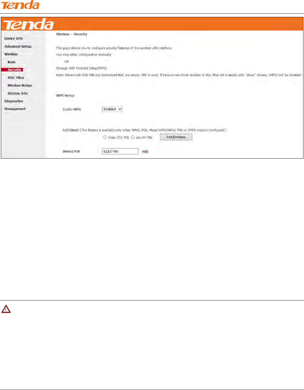
WPS Setup
Wireless N300 ADSL2+ High Power Modem Router
133
Wi-Fi Protected Setup makes it easy for home users who know little of wireless security to establish a home network, as
well as to add new devices to an existing network without entering long passphrases or complicate configurations.
Simply enter a PIN code on the device web interface or press hardware WPS button (on the back panel of the device) and
a secure wireless connection is established.
WPS (hardware button): Press the hardware WPS button on the device for 1 second and the WPS LED will keep
blinking for about 2 minutes. Within the 2 minutes, press the WPS button on your wireless computer or other device.
When the WPS LED displays a solid light, the device has joined your wireless network.
Device PIN: To use this option, you must know the PIN code from the wireless client and enter it in the corresponding
field on your device while using the same PIN code on client side for such connection.
Enable WPS: Check/uncheck to enable/disable the WPS function. It is disabled by default.
Note
1. To use the WPS security, the wireless client must be also WPS-capable.
2. When both STA PIN and Authorized MAC are empty, PBC is used. If Hide Access Point is enabled or Mac filter list is
empty with "allow" chosen, WPS2 will be disabled.
3. WPS only supports WPA2, which means only when you select “WPA2” encryption or “Open”, you can change WPS
status.
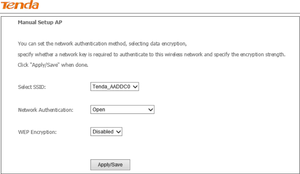
Manual Setup AP
Wireless N300 ADSL2+ High Power Modem Router
134
You can set the network authentication method, select data encryption, specify whether a network key is required to
authenticate to this wireless network and specify the encryption strength.
Click "Apply/Save" when done.
Network Authentication: Select Open, Shared, 802.1X, WPA-PSK, WPA2-PSK or Mixed WPA/WPA2-PSK from the
drop-down list to encrypt your wireless network. Depending on the type of network authentication you select, you will
be prompted to enter corresponding settings.
WEP Encryption: Select Enabled or Disabled.
Encryption Strength: Select 128-bit or 64-bit.
Current Network Key: Select a network key to be active.
Network Key 1/2/3/4: Enter 13 ASCII characters or 26 hexadecimal digits for 128-bit encryption keys; enter 5 ASCII
characters or 10 hexadecimal digits for 64-bit encryption keys.
WPA/WAPI passphrase: Enter a WPA/WAPI network key.
WPA Group Rekey Interval: Specify a key update interval.
WPA/WAPI Encryption: Select AES or TKIP+AES.
Apply/Save: Click it to apply the current configurations.
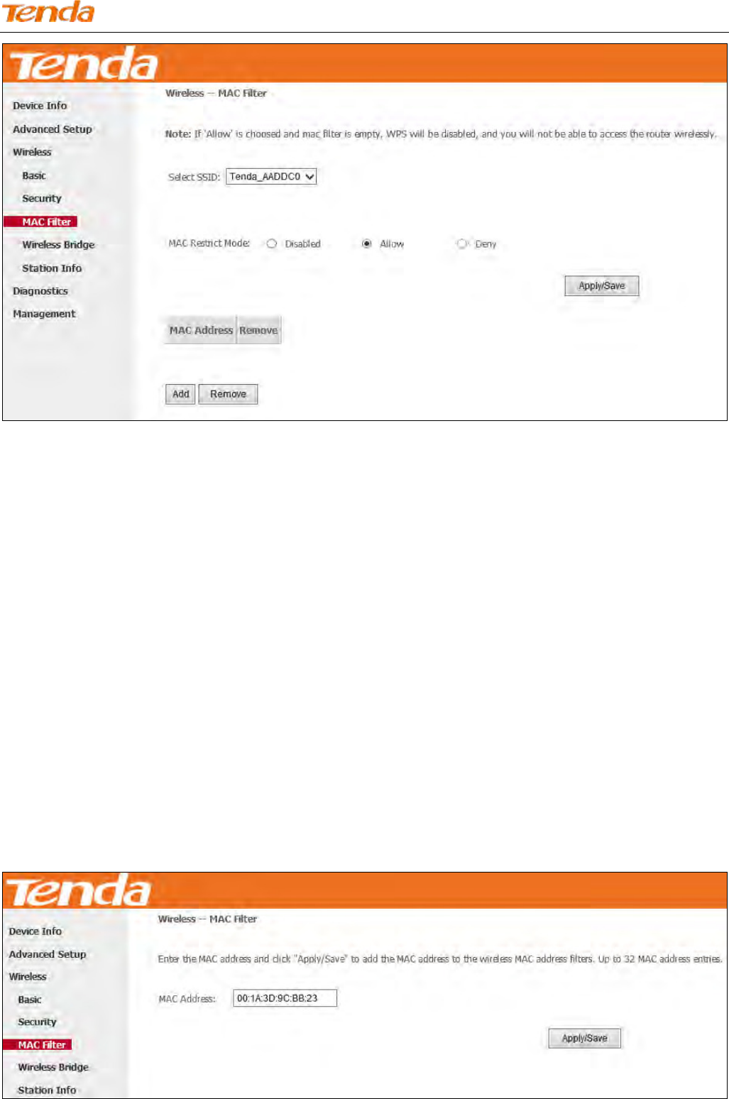
4.3.3 MAC Filter
The MAC-based Wireless Access Control feature can be used to allow or disallow clients to connect to your wireless
network.
Wireless N300 ADSL2+ High Power Modem Router
135
MAC Restrict Mode: Disabled, Allow and Deny
Allow: Only allow PCs at specified MAC addresses (in the list) to connect to your wireless network.
Deny: Block only PCs at specified MAC addresses from connecting to your wireless network.
Disabled: Disable MAC filter feature.
Add: Click to add a MAC address.
Remove: To delete an existing MAC address, first check the Remove box next to the MAC address in list and then click
this button.
Example: To allow only the PC at the MAC address of 00:1A:3D:9C:BB:23 to connect to your wireless network, do as
follows:
1. Select Allow.
2. Click the Apply/Save button.
3. Enter 00:1A:3D:9C:BB:23 in the MAC address box as shown in the figure below and click Apply/Save.
Wireless N300 ADSL2+ High Power Modem Router
136
Note
1) If you select “Allow” MAC restrict mode and directly click Apply/Save instead of adding any MAC address to be
filtered, WPS will be disabled (You can go to Wireless > Security to check WPS status).
2) If you want to change the MAC filter mode above from “Allow” to “Deny”, just select Deny and click Apply/Save.
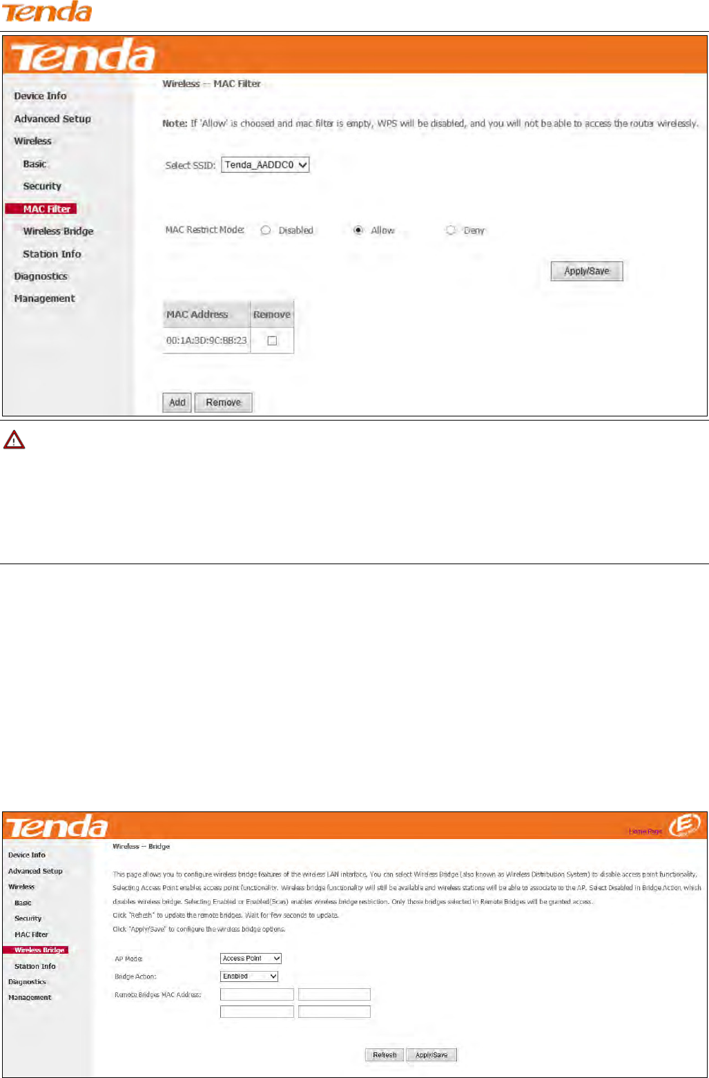
4.3.4 Wireless Bridge
This page allows you to configure wireless bridge (also known as Wireless Distribution System) features of the wireless
LAN interface.
Wireless distribution system (WDS) is a system enabling the wireless interconnection of access points in an IEEE 802.11
network. It allows a wireless network to be extended using multiple access points without the traditional requirement for
a wired backbone to link them.
Wireless N300 ADSL2+ High Power Modem Router
137
AP Mode: You can select Wireless Bridge (also known as Wireless Distribution System) to disable access point
functionality. Selecting Access Point enables access point functionality. Wireless bridge functionality will still be
available and wireless stations will be able to associate to the AP.
Bridge Action: There are three options available: Enabled, Enabled (Scan) and Disabled. Disabled in Bridge Action
means disabling wireless bridge restriction. Any wireless bridge will be granted access. Enabled or Enabled (Scan)
means enabling wireless bridge restriction. Only those bridges selected in Remote Bridges will be granted access. The
Enabled (Scan) affords auto scanning the remote bridges.
Remote Bridges MAC Address: Specify the MAC address of the remote bridge. If you select the Enabled (Scan)
option in Bridge Restrict, system automatically scans the remote bridges and you only need to select those bridges and
their MAC addresses will be added to automatically.
Refresh: Click it to update the remote bridges. Wait for seconds to update.
Apply/Save: Click it to apply and save the settings.
Note
The WDS feature can only be implemented between 2 WDS-capable wireless devices. Plus, SSID, channel, security
settings and security key must be exactly the same on both such devices.
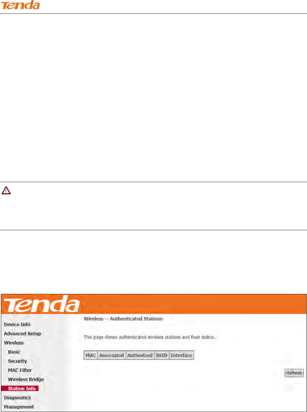
4.3.5 Station Info
This page shows authenticated wireless stations and their status.
Wireless N300 ADSL2+ High Power Modem Router
138
4.4 Diagnostics
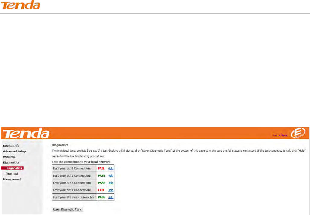
4.4.1 Diagnostics
The modem router is capable of testing the connection to your DSL service provider, the connection to your Internet
service provider and the connection to your local network. If a test displays a fail status, click "Rerun Diagnostic Tests"
at the bottom of this page several times to verify the connection status. If the test continues to fail, click "Help" and
follow the troubleshooting procedures.
Pass: Indicates that the Ethernet interface from your computer is connected to the LAN port of your Broadband Router.
Fail: Indicates that the Broadband Router does not detect the Ethernet interface on your computer.
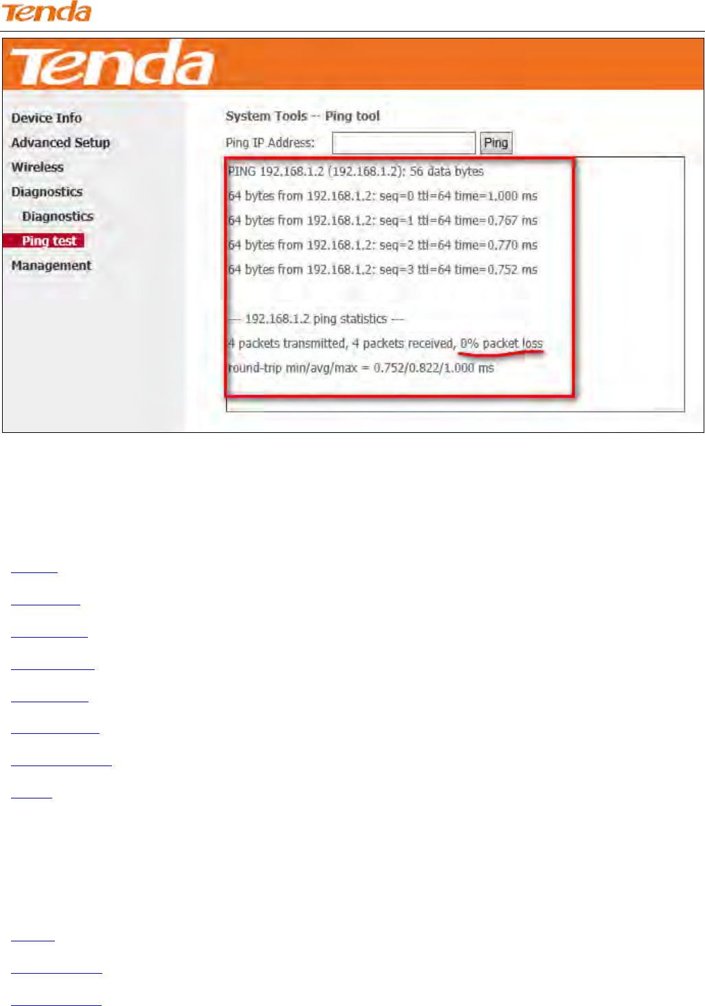
4.4.2 Ping test
Ping utility can help test whether the device has built a proper connection with your host.
Type in the IP address of your host in the Ping IP Address field, and click Ping. If you get a similar screen shown as
below, it indicates the connection between the Ping object (Here is 192.168.1.2) and the device has been established.
Wireless N300 ADSL2+ High Power Modem Router
139
4.5 Management
This section explains the following information:
• Settings
• System Log
• SNMP Agent
• TR-069 Client
• Internet Time
• Access Control
• Update Firmware
• Reboot
4.5.1 Settings
This section explains the following information:
• Backup
• Restore Backup
• Restore Default
Wireless N300 ADSL2+ High Power Modem Router
140
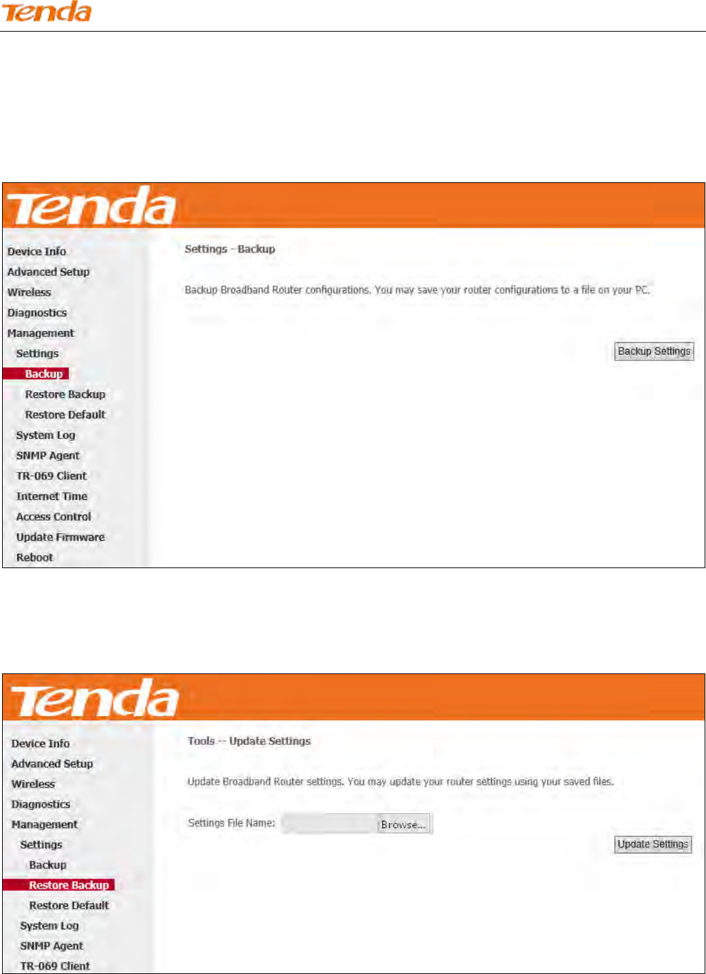
Backup
Here you can save a copy of your device’s configurations to your computer. Once you have configured the device, you
can save these settings to a configuration file on your local hard drive. The configuration file can later be imported to
your device in case the device is reset to factory default settings.
Restore Backup
Here you can restore the configuration from a backup file saved on your PC.
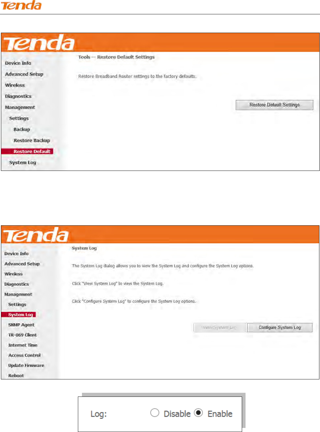
Restore Default
Under some circumstances (for example, unfortunately forgetting the login password or cannot locate network fault),
Wireless N300 ADSL2+ High Power Modem Router
141
you may need to remove the existing configuration and restore the factory default settings.
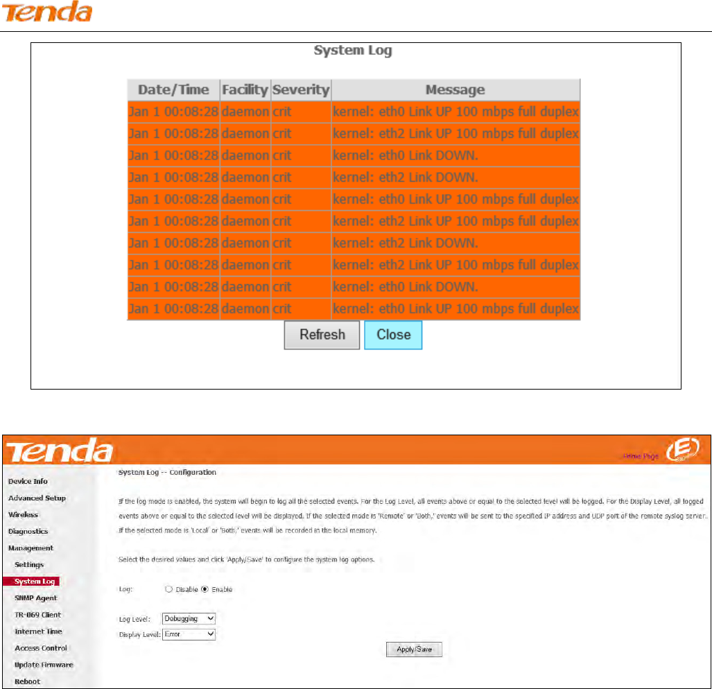
4.5.2 System Log
Here you can view and configure the system log.
To view the System Log, firstly ensure log is enabled, otherwise you cannot read any log.
Wireless N300 ADSL2+ High Power Modem Router
142
To configure the system log, click Configure System Log.
Log: If Enable is selected, the system will begin to log all the selected events.
Log Level: Set the log level. All events above or equal to the selected level will be logged.
Display Level: Set the log display level. All logged events above or equal to the selected level will be displayed.
Apply/Save: click to apply and save the system log settings.
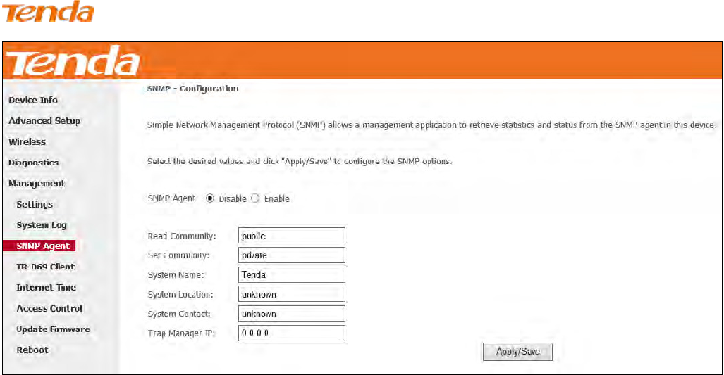
4.5.3 SNMP Agent
Simple Network Management Protocol (SNMP) allows a management application to retrieve statistics and status from
the SNMP agent in this device.
Wireless N300 ADSL2+ High Power Modem Router
143
SNMP Agent: Select “Enable” to activate the SNMP Agent feature or “Disable” to deactivate it.
Read Community: Specify a Read Community string. The default is public.
Set Community: Specify a Set Community string. The default is private.
System Name: Specify a descriptive system name.
System Location: Specify a system location.
System Contact: Specify a system contact.
Trap Manager IP: Specify the IP address of the Trap Manager.
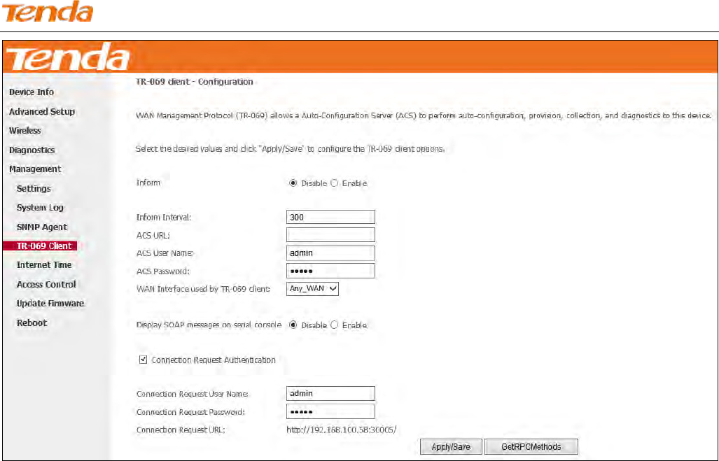
4.5.4 TR-069 Client
WAN Management Protocol (TR-069) allows an Auto-Configuration Server (ACS) to perform auto-configuration,
provision, collection, and diagnostics to this device.
Click the TR-069 Client tab to enter the TR-069 Client configuration screen as seen below:
Wireless N300 ADSL2+ High Power Modem Router
144
Inform: Select Enable/Disable to enable/disable the TR-069 Client function. By default, it is disabled.
Inform Interval: Specify the inform interval.
ACS URL: Enter the ACS (Auto-Configuration Server) URL address.
ACS User Name: Enter the ACS (Auto-Configuration Server) user name.
ACS Password: Enter the ACS (Auto-Configuration Server) password.
WAN Interface used by TR-069 client: Select the WAN interface used by the TR-069 client from the drop-down list.
Display SOAP messages on serial console: If Enable is selected, SOAP messages will be displayed on serial console; if
Disable is selected, SOAP messages will not be displayed on serial console.
Connection Request Authentication: Check/uncheck to enable/disable the connection request authentication.
Connection Request User Name: Enter the connection request user name.
Connection Request Password: Enter the connection request password.
Connection Request URL: Specify the connection request URL.
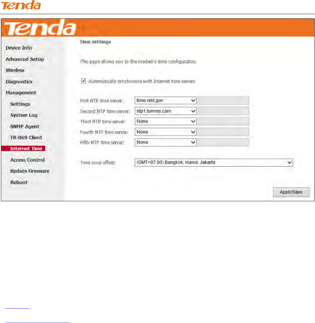
4.5.5 Internet Time
This page is used to set the router’s system time. If Automatically synchronize with Internet time servers is checked,
the system will automatically connect to NTP server to synchronize the time.
Wireless N300 ADSL2+ High Power Modem Router
145
First/Second/Third/Fourth/Fifth NTP time server: Select a NTP time server from the drop-down list. If the NTP time
server you are looking for is not included in the list, select “Other” and then enter it manually in the box.
Time zone offset: Select your time zone from the drop-down list.
4.5.6 Access Control
This section explains the following information:
• Password
• Access Control - Service
Password
Access to your broadband router is controlled through two user accounts: “admin” and “support”.
The user name "admin" has unrestricted access to change and view configuration of your Broadband Router.
The user name "support" is used to allow an ISP technician to access your Broadband Router for maintenance and to run
diagnostics.
Wireless N300 ADSL2+ High Power Modem Router
146
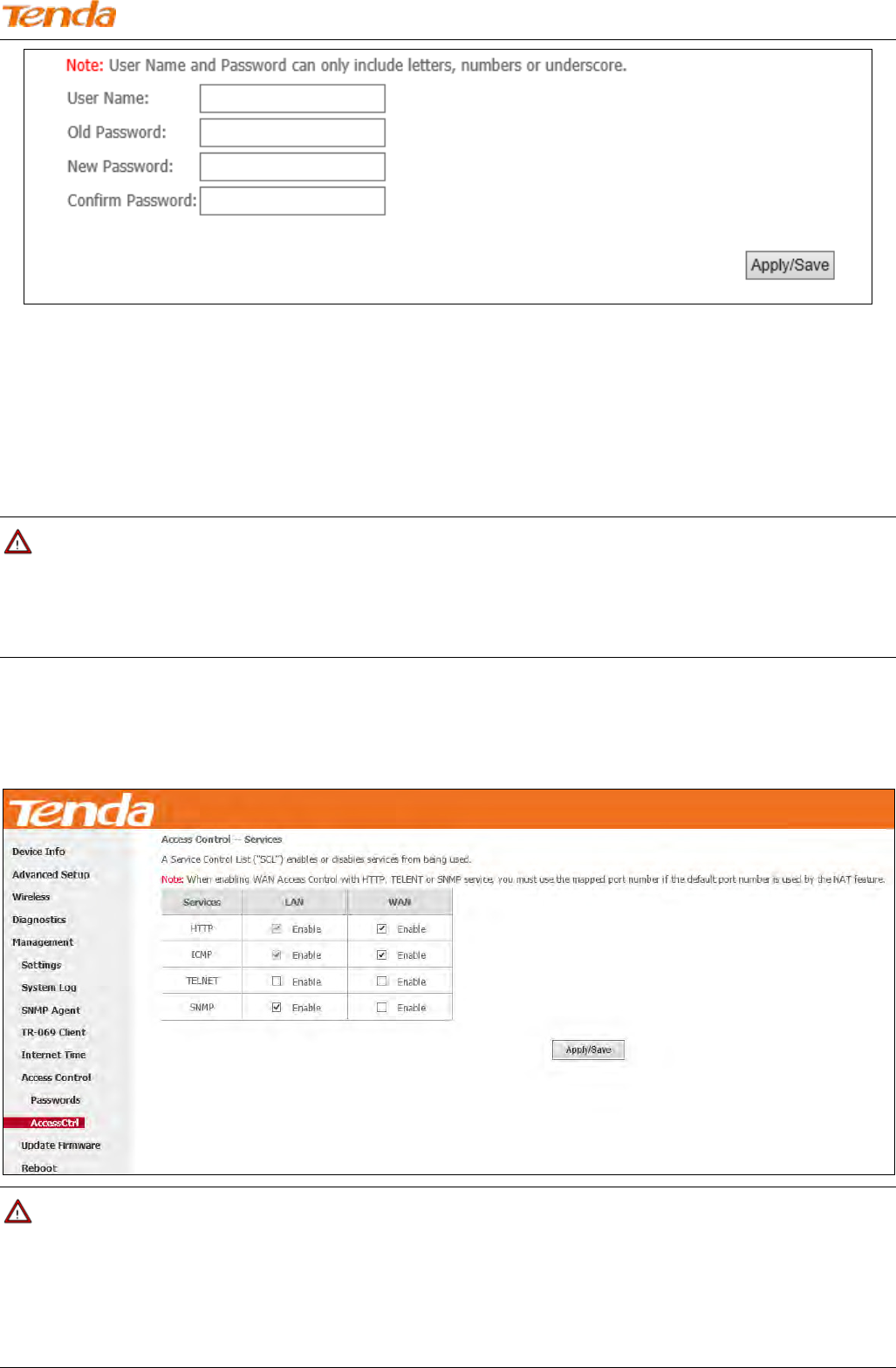
User Name: Enter the user name of up to 16 characters.
Old Password: Enter the old password of up to 16 characters.
New Password: Enter a new password of up to 16 characters.
Confirm Password: Re-enter to confirm the new password.
Apply/Save: Click to change or create passwords.
Note
1. Password cannot contain a space.
2. The password of “support” account cannot be changed. It only can be “support”.
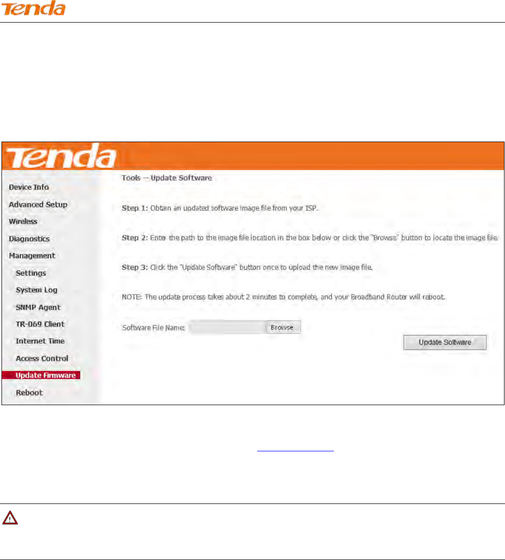
Access Control - Service
Here you can manage the device either from LAN or WAN side using HTTP, ICMP, TELNET, and SNMP.
Note
1. If you are not an advanced user, we suggest you keep the default settings.
2. To access the device from the LAN side, you must use the LAN IP address and log in as "admin"; to access the
device from the WAN side, you must use the WAN IP address and log in as "support".
Wireless N300 ADSL2+ High Power Modem Router
147
4.5.7 Update Firmware
New firmware is released periodically to improve the functionality of your device and add any new features. If you run
into a problem with a specific feature of the device, you could log in to our website (www.tendacn.com) to download the
latest firmware to update your device.
To update software, do as follows:
1) Download an upgrading firmware file from our website: www.tendacn.com and save it in your local hard drive.
2) Click the "Browse" button to locate and select the upgrading file.
3) Click the "Update Software" button to upload the upgrading file and update the software.
Note
The update process takes about 2 minutes to complete, and your Broadband Router will reboot.
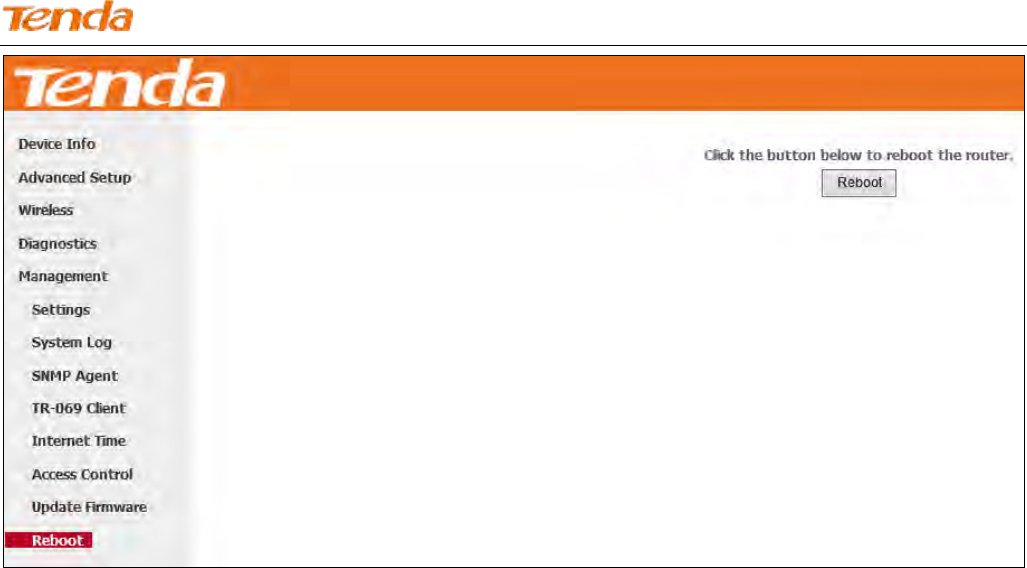
4.5.8 Reboot
Click the Reboot button to reboot the router.
Wireless N300 ADSL2+ High Power Modem Router
148
Wireless N300 ADSL2+ High Power Modem Router
149
Appendix 1 Configure Your PC
Screens to configure TCP/IP properties in other Operating Systems are similar to those below.
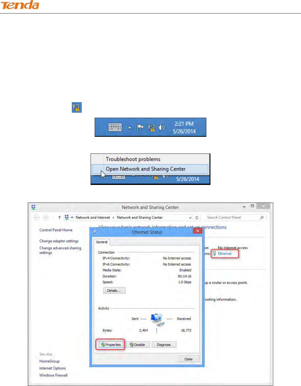
Windows 8
Step 1: Right click the icon on the bottom right corner of your desktop.
Step 2: Click Open Network and Sharing Center.
Step 3: Click Ethernet -> Properties.
Step 4: Find and double click Internet Protocol Version 4(TCP/IPv4).
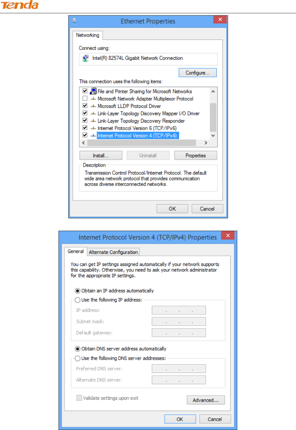
Wireless N300 ADSL2+ High Power Modem Router
150
Step 5: Select Obtain an IP address automatically and Obtain DNS server address automatically and click OK.
Step 6: Click OK on the Ethernet Properties window (see Step 4 for the screenshot).
Wireless N300 ADSL2+ High Power Modem Router
151
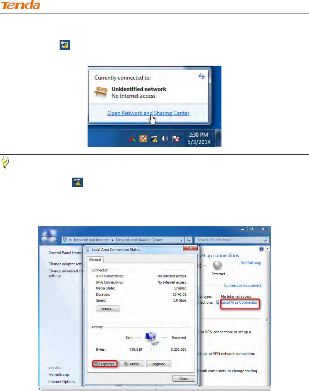
Windows 7
Step 1: Click the icon on the bottom right corner of your desktop.
Step 2: Click Open Network and Sharing Center.
Tip:
If you cannot find the icon on the bottom right corner of your desktop, follow steps below: Click Start -> Control
Panel -> Network and Internet -> Network and Sharing Center.
Step 3: Click Local Area Connection -> Properties.
Step 4: Find and double click Internet Protocol Version 4(TCP/IPv4).
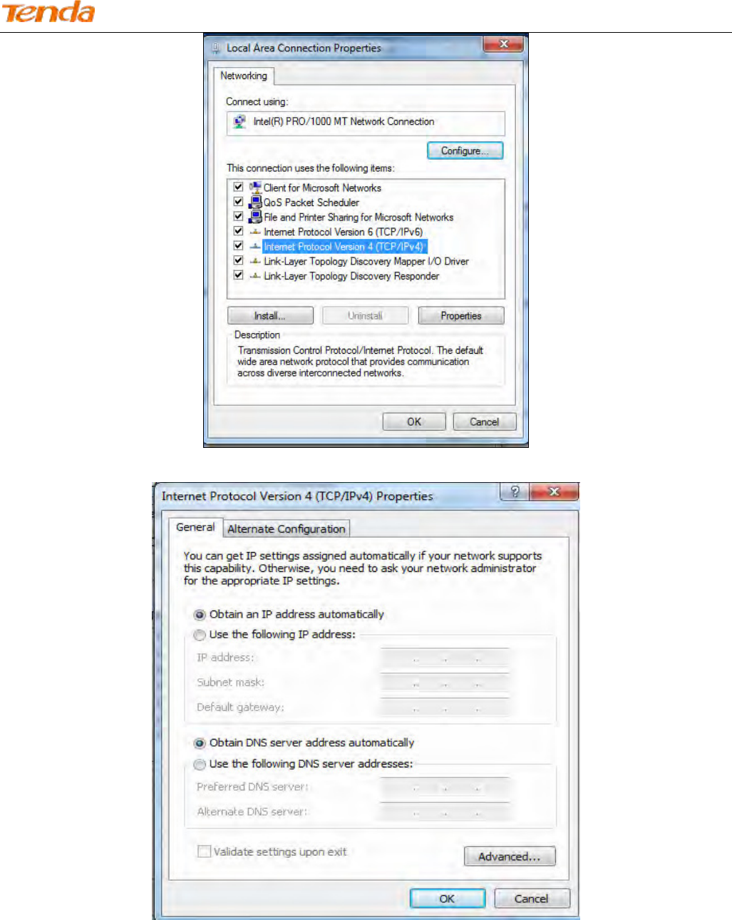
Wireless N300 ADSL2+ High Power Modem Router
152
Step 5: Select Obtain an IP address automatically and Obtain DNS server address automatically and click OK.
Step 6: Click OK on the Local Area Connection Properties window (see Step 4 for the screenshot).
Wireless N300 ADSL2+ High Power Modem Router
153
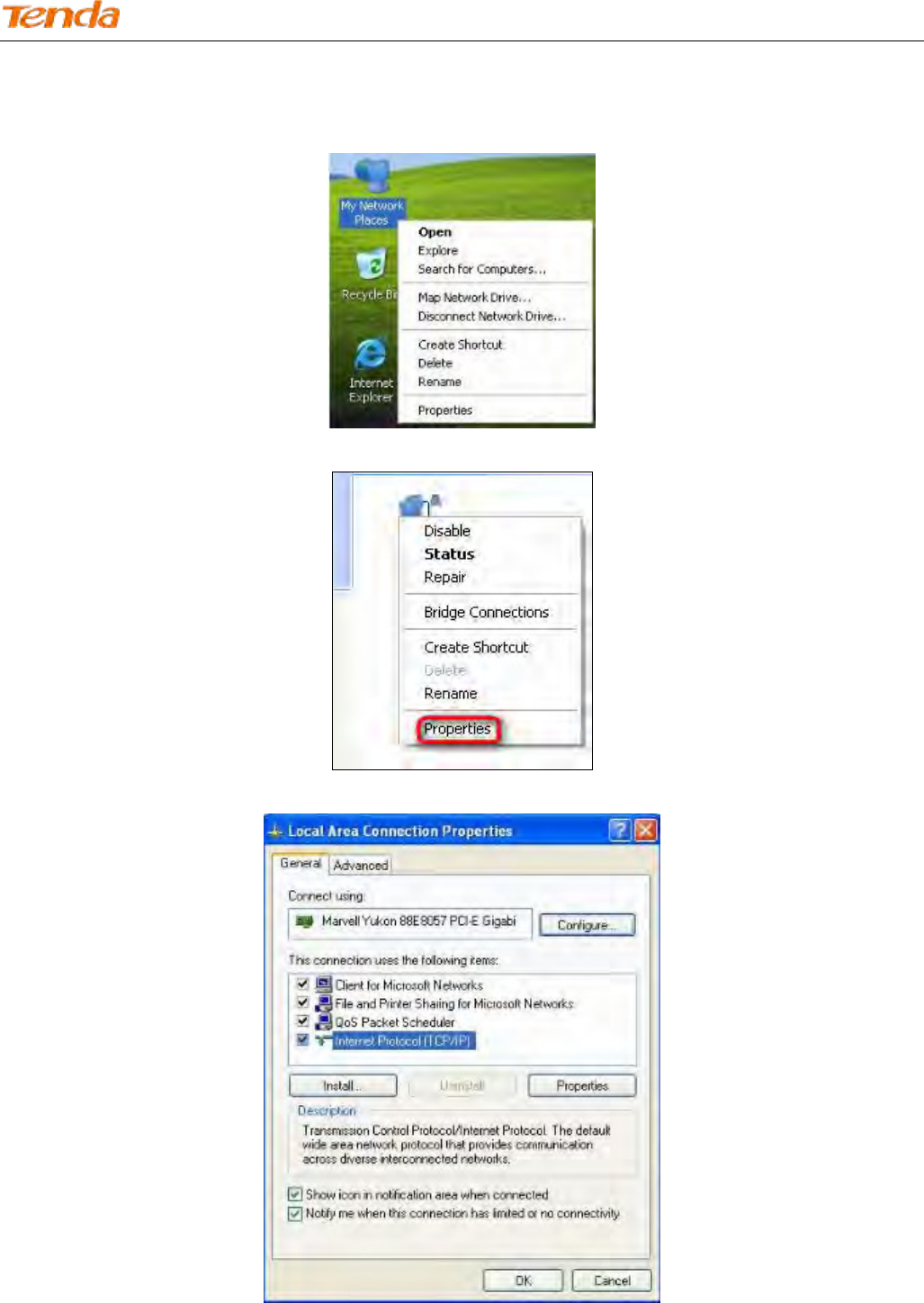
Windows XP
Step 1: Right click My Network Places on your desktop and select Properties.
Step 2: Right click Local Area Connection and select Properties.
Step 3: Scroll down to find and double click Internet Protocol (TCP/IP).
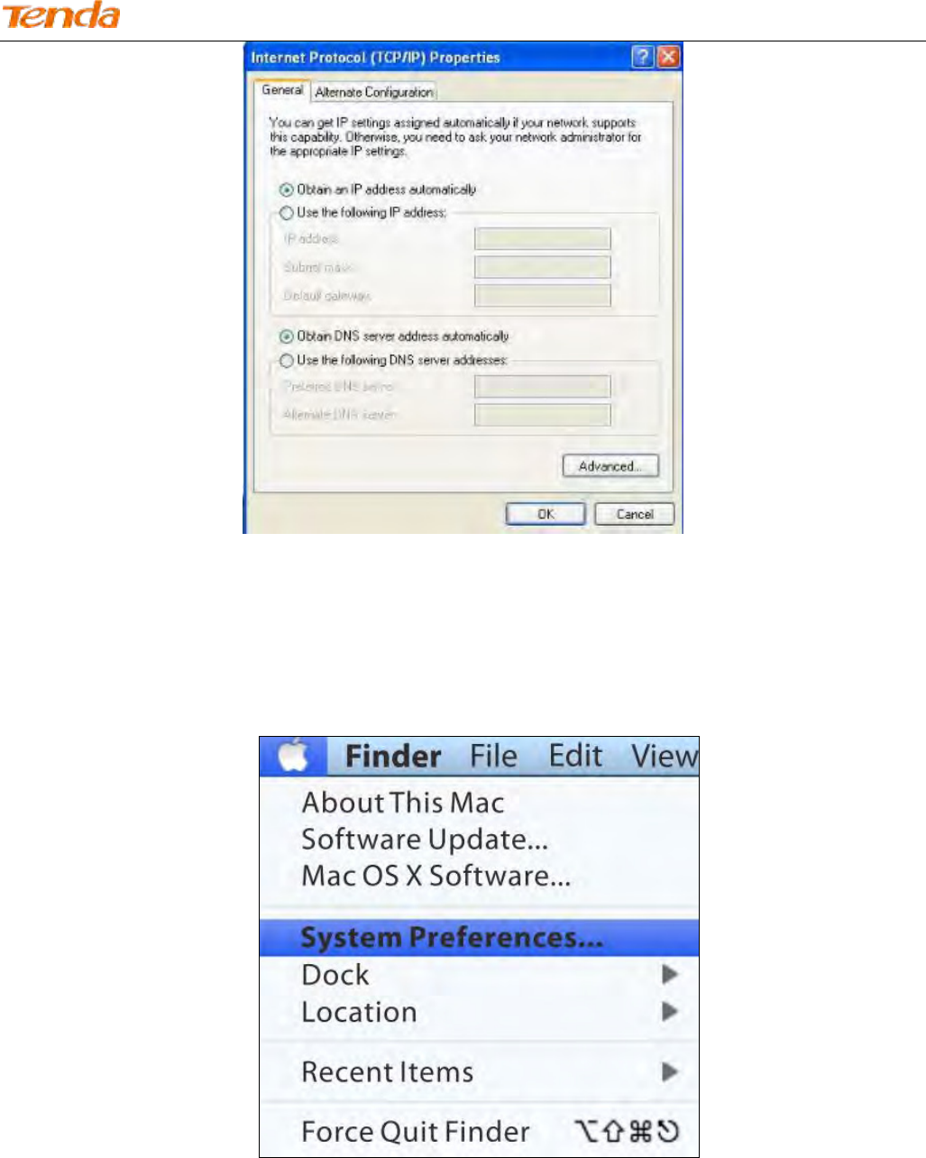
Step 4: Select Obtain an IP address automatically and Obtain DNS server address automatically and click OK.
Wireless N300 ADSL2+ High Power Modem Router
154
Step 5: Click OK on the Local Area Connection Properties window (see Step 3 for the screenshot).
MAC
Step 1: Click on the Apple icon from the top left corner and select System Preferences.
Step 2: click Network from Internet & Network.
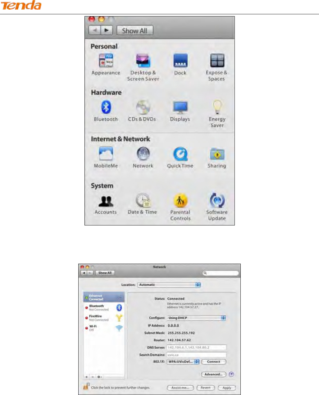
Wireless N300 ADSL2+ High Power Modem Router
155
Step 3: Click on Ethernet, choosing Using DHCP from configure, and click Apply to save.

Wireless N300 ADSL2+ High Power Modem Router
156
Appendix 2 Join Your Wireless Network
Tip:
1. The PC you use must have installed a wireless network adapter.
2. The device's SSID is "Tenda_XXXXXX" by default (where "XXXXXX" is the last six characters of its MAC address).
You can find the MAC address and/or SSID on the label attached to the device’s bottom).
Windows 8
Step 1: Click the icon on the bottom right corner of your desktop.
Step 2: Select your wireless network from the list, click Connect and then follow onscreen instructions.
Tip:
1. If you cannot find the icon , please move your mouse to the top right corner of your desktop, select Settings ->
Control Panel -> Network and Internet -> Network and Sharing Center -> Change adapter settings, right click
Wi-Fi and select Connect/Disconnect.
2. If you cannot find your wireless network from the list, ensure the Airplane Mode is not enabled on your PC.
Step 3: When your wireless network is connected successfully, the following screen will appear.
Wireless N300 ADSL2+ High Power Modem Router
157
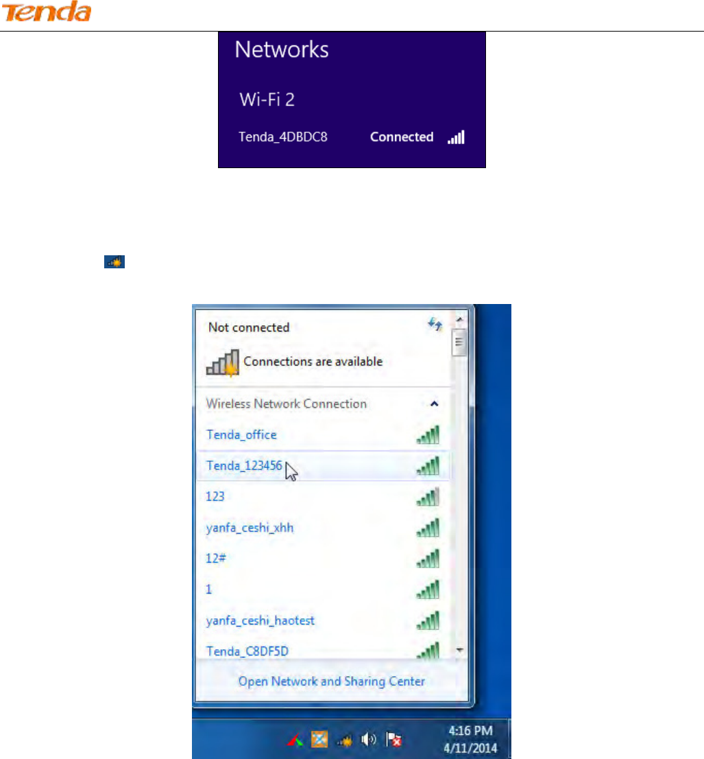
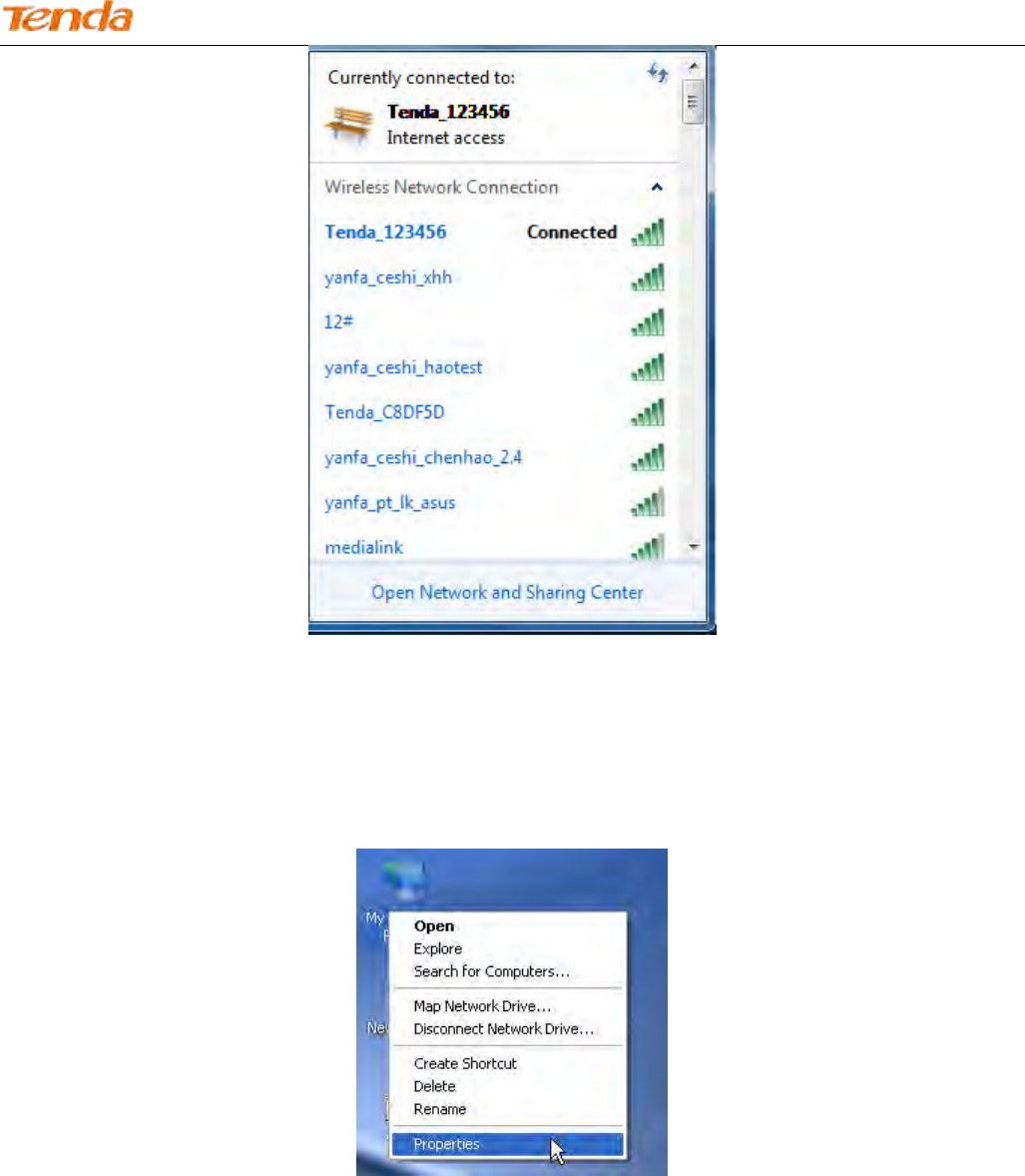
Windows 7
1. Click the icon on the bottom right corner of your desktop.
2. Double click your SSID (wireless network name) and then follow onscreen instructions.
3. When your SSID (wireless network name) displays Connected as shown below, you’ve connected to it for Internet
access successfully.
Wireless N300 ADSL2+ High Power Modem Router
158
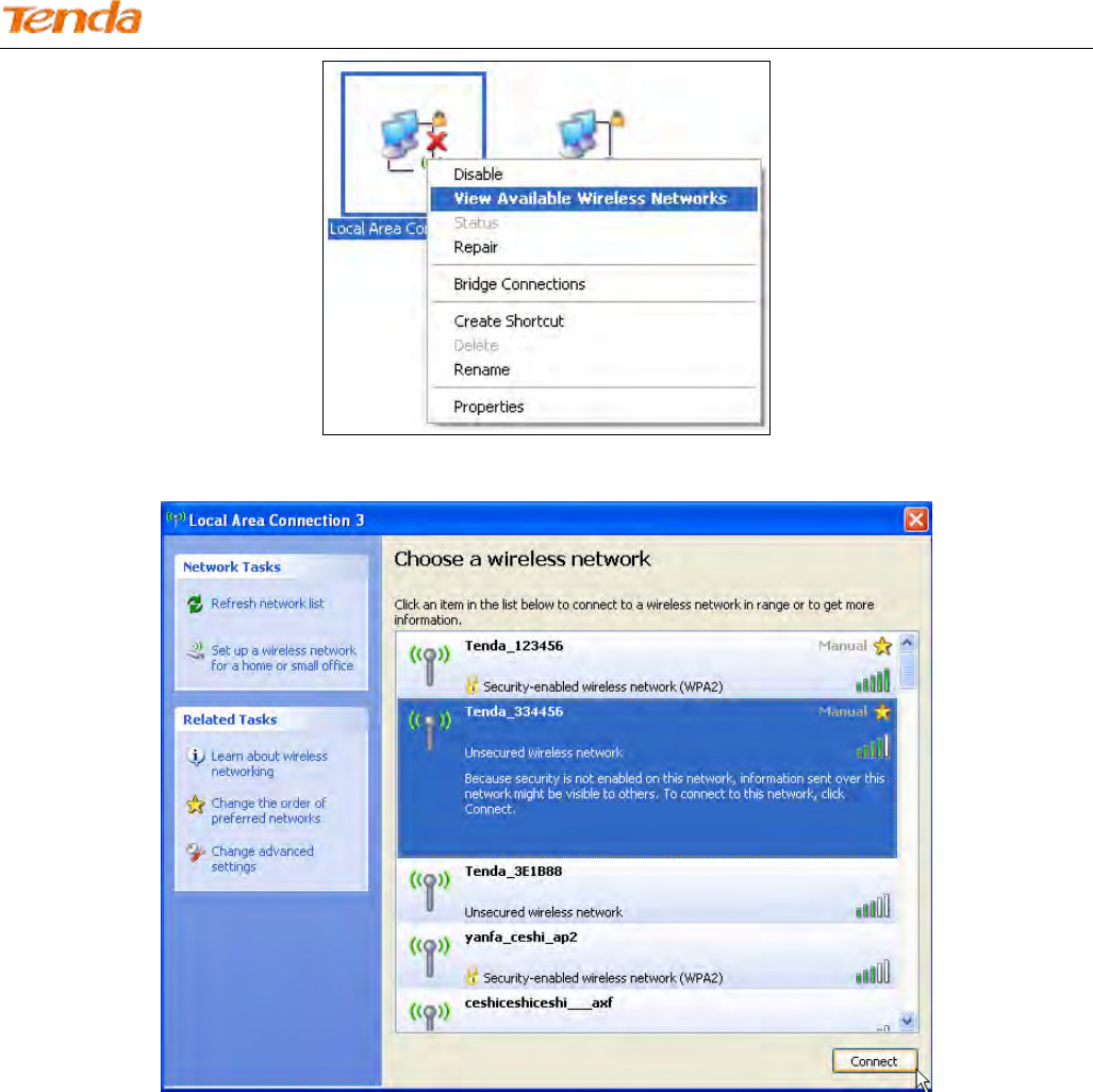
Windows XP
1. Right click My Network Places, and select Properties.
2. Right click Local Area Connection, and select View Available Wireless Networks from the pop-up submenu.
Wireless N300 ADSL2+ High Power Modem Router
159
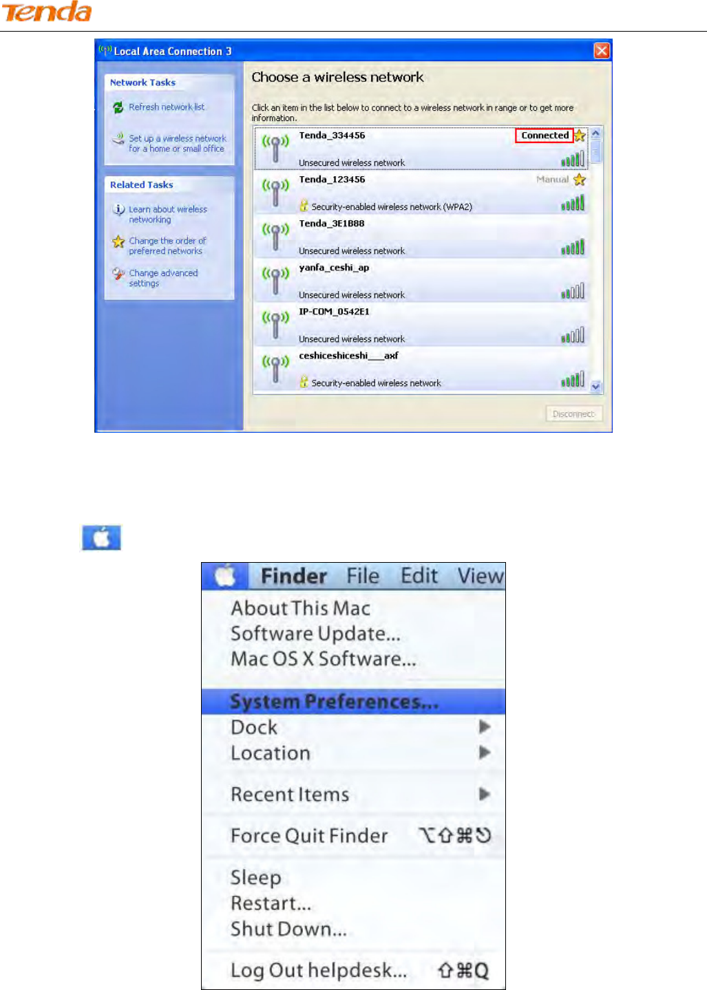
3. Select your wireless network from the list and then follow onscreen instructions.
4. When your SSID (wireless network name) displays Connected as shown below, you’ve connected to it for Internet
access successfully.
Wireless N300 ADSL2+ High Power Modem Router
160
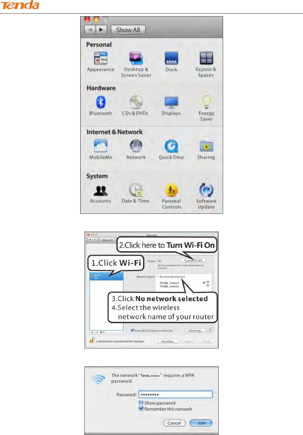
MAC
Step 1: Click > System Preferences.
Step 2: Select Network from Internet & Network.
Wireless N300 ADSL2+ High Power Modem Router
161
Step 3:
Step 4: Enter the wireless password, and click Join to connect the selected SSID.
Wireless N300 ADSL2+ High Power Modem Router
162
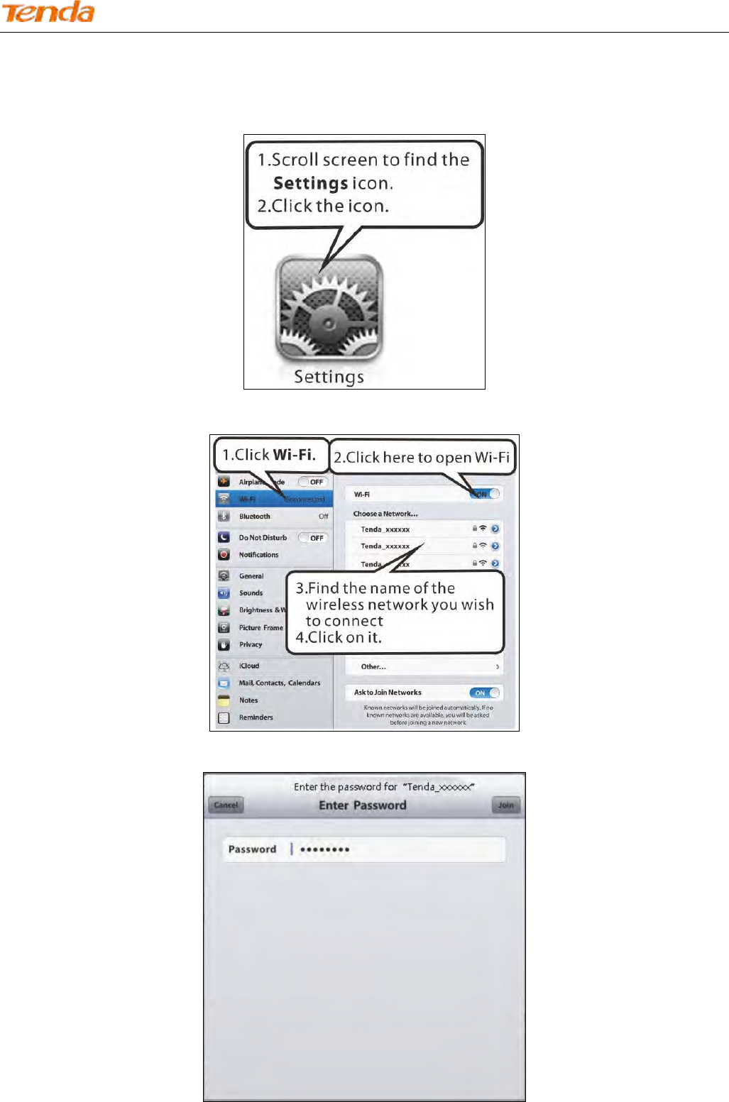
iPhone/iPad
Step 1:
Step 2:
Step 3: Enter the passwork and click Join to connect the selected SSID.
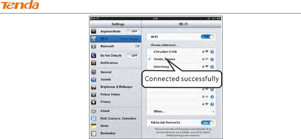
Wireless N300 ADSL2+ High Power Modem Router
163

Wireless N300 ADSL2+ High Power Modem Router
164
Appendix 3 FAQs
1. What information should I have to access the Internet via the ADSL uplink?
If you have DSL broadband service, you might need the following information to set up your modem router.
• Active Internet service provided by an ADSL account
• The ISP configuration information for your DSL account
- ISP login name and password
- Fixed or static IP address
Depending on how your ISP set up your Internet account, you could need to know the Virtual path identifier (VPI) and
virtual channel identifier (VCI) parameters for a manual setup.
2. I cannot access the device's management interface. What should I do?
1) Verify the physical connection (namely, the Ethernet cable) between your PC and the device. For details, see
Chapter 2 Hardware Install hereof.
2) Double check the TCP/IP settings on your PC. For details, see Appendix 1 Configure Your PC hereof.
3) Press the RST/WPS button on the device for about 10 seconds to reset the device and then re-access the
management interface with the default username and password.
4) Change the Ethernet cable that connects your PC and the device.
5) Try accessing device management interface from other PCs, smart phones or iPads.
6) Connect your PC alone to one of the LAN ports on the device.
3. I forget the wireless security key. What should I do? (How do I configure or change the security key?)
Try the default security key, which can be seen from the label attached to the device bottom.
If step 1 works, access the device web manager and customize a new security key.
If step 1 does not work, press the RST/WPS button on the device for about 10 seconds to restore factory default
settings. And then log in to the device web manager to set a new security key.
4. My notebook is unable to search wireless networks, what should I do?
1) Verify that wireless service is enabled on your notebook by checking the wireless hardware or software button on
your notebook. The hardware button is usually located on the side of your notebook. Note that some notebooks
may not have such hardware button. Software button can be implemented by pressing Fn+ . Fn is situated on
the bottom left corner of your keyboard, may be any key between F1-F12 depending on what type of
keyboard you are using.
2) Log in to the device, select Wireless > Basic and change the wireless network name (SSID). Then search again.

Wireless N300 ADSL2+ High Power Modem Router
165
Follow below steps to verify that wireless service is enabled on your notebook (for Windows XP OS only).
From the desktop, right click on the My Computer icon and select Manage. Select Services and Applications, double
click Services and view the status of Wireless Zero Configuration. If Status dose not display Started, right click the
Wireless Zero Configuration and select Start; if Startup Type displays Disabled, right click the Wireless Zero
Configuration, select Properties; from the Startup Type drop-down list box, select Automatic and then click Start in
Service Status.
5. Why cannot I connect to the searched wireless network?
1) Verify that you entered a correct security key.
2) Log in to the device, select Wireless > Basic and change the wireless network name (SSID). Then connect again.
3) Log in to the device, select Wireless > Security and change the security settings. Then connect again.
6. Where should I place the wireless device for optimum performance?
1) Place it in the center to extend wireless coverage as far as possible.
2) Never place the device near to metal objects or in direct sunshine.
3) Keep it far away from devices that use the 2.4 GHz radio wave frequency to transmit and receive data, such as
802.11g/n wireless network devices, electronic devices such as cell phones, radio transmitters, blue tooth, cordless
phones, fax machine, refrigerator and microwaves to avoid electronic interference.

Wireless N300 ADSL2+ High Power Modem Router
166
Appendix 4 VPI/VCI List
The following table lists common ISPs and their VPI and VCI numbers. If you cannot locate your ISP and their VPI and
VCI information here, ask your ISP to provide it.
Country
ISP
VPI
VCI
Encapsulation
Australia
Telstra
8
35
PPPoA LLC
Australia
GoldenIT
8
35
_PPPOA_VCMUX
Australia
Telstra Bigpond
8
35
PPPOE_LLC
Australia
OptusNET
8
35
PPPOE_VCMUX
Australia
AAPT
8
35
PPPOE_VCMUX
Australia
ADSL Direct
8
35
PPPOE_LLC
Australia
Ausie Broadband
8
35
PPPOE_LLC
Australia
Australia On Line
8
35
PPPOA_VCMUX
Australia
Connexus
8
35
PPPOE_LLC
Australia
Dodo
8
35
PPPOE_LLC
Australia
Gotalk
8
35
PPPOE_VCMUX
Australia
Internode
8
35
PPPOE_VCMUX
Australia
iPrimus
8
35
PPPOA_VCMUX
Australia
Netspace
8
35
PPPOE_VCMUX
Australia
Southern Cross Telco
8
35
PPPOE_LLC
Australia
TPG Internet
8
35
PPPOE_LLC
Argentina
Telecom
0
33
PPPoE LLC
Argentina
Telefonica
8
35
PPPoE LLC
Argentina
1
33
PPPoA VC-MUX
Belgium
ADSL Office
8
35
1483 Routed IP LLC
Belgium
Turboline
8
35
PPPoA LLC
Belgium
Turboline
8
35
1483 Bridged IP LLC
Belgium
ADSL Office
8
35
1483 Bridged IP LLC
Bolivia
0
34
1483 Routed IP LLC
Brazil
Brasil Telcom
0
35
PPPoE LLC
Brazil
Telefonica
8
35
PPPoE LLC

Wireless N300 ADSL2+ High Power Modem Router
167
Brazil
Telmar
0
33
PPPoE LLC
Brazil
South Region
1
32
PPPoE LLC
Canada
Primus Canada
0
35
PPPoE LLC
Canada
Rogers Canada (1)
0
35
PPPoE LLC
Canada
Rogers Canada (2)
8
35
1483 Bridged IP LLC
Canada
Rogers Canada (3)
0
35
1484 Bridged IP LLC
Canada
BellSouth(1) Canada
8
35
PPPoE LLC
Canada
BellSouth(2) Canada
0
35
PPPoE LLC
Canada
Sprint (1) Canada
0
35
PPPoA LLC
Canada
Sprint (2) Canada
8
35
PPPoE LLC
Canada
Verizon (1) Canada
0
35
PPPoE LLC
Canada
Verizon (2) Canada
0
35
1483 Bridged IP LLC
Colombia
EMCALI
0
33
PPPoA VC-MUX
Columbia
ETB
0
33
PPPoE LLC
Costa Rica
ICE
1
50
1483 Routed IP LLC
Czech Republic
8
48
1483 Bridged IP LLC
Denmark
Cybercity, Tiscali
0
35
PPPoA VC-MUX
Dominican Republic
0
33
1483 Bridged IP LLC
Dubai
0
50
1483 Bridged IP LLC
Egypt:
TE-data
0
35
1483 Bridged IP LLC
Egypt:
Linkdsl
0
35
1483 Bridged IP LLC
Egypt:
Vodafone
8
35
1483 Bridged IP LLC
Finland
Saunalahti
0
100
1483 Bridged IP LLC
Finland
Elisa
0
100
1483 Bridged IP LLC
Finland
DNA
0
100
1483 Bridged IP LLC
Finland
Sonera
0
35
1483 Bridged IP LLC
France
Free
8
36
LLC
France (1)
Orange
8
35
PPPoE LLC
France (2)
8
67
PPPoE LLC
France (3)
SFR
8
35
PPPoA VC-MUX
Germany
1
32
PPPoE LLC

Wireless N300 ADSL2+ High Power Modem Router
168
Hungary
Sci-Network
0
35
PPPoE LLC
Iceland
Islandssimi
0
35
PPPoA VC-MUX
Iceland
Siminn
8
48
PPPoA VC-MUX
India
Airtel
1
32
1483 Bridged IP LLC
India
BSNL
0
35
1483 Bridged IP LLC
India
MTNL
0
35
1483 Bridged IP LLC
India
RELIANCE
COMMUNICATION
0
35
PPPOE LLC
India
TATA INDICOM
0
32
PPPOE LLC
India
CONNECT
1
32
PPPOE LLC
Indonesia Speedy
Telkomnet
8
81
PPPoE LLC
Iran
[Shatel]
Aria-Rasaneh-Tadbir
0
35
PPPOE LLC
Iran
Asia-Tech
0
35
PPPOE LLC
Iran
Pars-Online (Tehran)
0
35
PPPOE LLC
Iran
Pars-Online (Provinces)
0
59
PPPOE LLC
Iran
[Saba-Net]
Neda-Gostar-Saba
0
35
PPPOE LLC
Iran
Pishgaman-Tose
0
35
PPPOE LLC
Iran
Fan-Ava
8
35
PPPOE LLC
Iran
Datak
0
35
PPPOE LLC
Iran
Laser (General)
0
35
PPPOE LLC
Iran
Laser (Privates)
0
32
PPPOE LLC
Iran
Asr-Enteghal-Dadeha
8
35
PPPOE LLC
Iran
Kara-Amin-Ertebat
0
33
PPPOE LLC
Iran
ITC
0
35
PPPOE LLC
Iran (1)
0
35
PPPoE LLC
Iran (2)
8
81
PPPoE LLC
Iran
Dadegostar Asre Novin
0
33
PPPOE LLC
Israel
8
35
PPPoA VC-MUX
Israel(1)
8
48
PPPoA VC-MUX

Wireless N300 ADSL2+ High Power Modem Router
169
Italy
8
35
1483 Bridged IP LLC
Italy
8
35
PPPoA VC-MUX
Jamaica (1)
8
35
PPPoA VC-MUX
Jamaica (2)
0
35
PPPoA VC-MUX
Jamaica (3)
8
35
1483 Bridged IP LLC SNAP
Jamaica (4)
0
35
1483 Bridged IP LLC SNAP
Kazakhstan
Kazakhtelecom
«Megaline»
0
40
LLC/SNAP Bridging
Kazakhstan
0
33
PPPoA VC-MUX
kuwait unitednetwork
0
33
1483 Bridged IP LLC
Malaysia
Streamyx
0
35
PPPOE LLC
Malaysia
0
35
PPPoE LLC
Mexico
Telmex (1)
8
81
PPPoE LLC
Mexico
Telmex (2)
8
35
PPPoE LLC
Mexico
Telmex (3)
0
81
PPPoE LLC
Mexico
Telmex (4)
0
35
PPPoE LLC
morocco
IAM
8
35
PPPOE
Netherlands
BBNED
0
35
PPPoA VC-MUX
Netherlands
MXSTREAM
8
48
1483 Bridged IP LLC
Netherlands
BBNED
0
35
1483 Bridged IP LLC
Netherlands
MX Stream
8
48
PPPoA VC-MUX
New Zealand
Xtra
0
35
PPPoA VC-MUX
New Zealand
Slingshot
0
100
PPPoA VC-MUX
Orange Nyumbani
(Kenya)
0
35
PPPoE LLC
Pakistan (PALESTINE)
8
35
1483 Bridged IP LLC
Pakistan for PTCL
0
103
1483 Bridged IP LLC
Pakistan (cyber net)
8
35
PPPoE LLC
Pakistan (linkDotnet)
0
35
PPPoA LLC
Pakistan(PTCL)
8
81
PPPoE LLc
Philippines(1)
0
35
1483 Bridged IP LLC
Philippines(2)
0
100
1483 Bridged IP LLC

Wireless N300 ADSL2+ High Power Modem Router
170
Portugal
0
35
PPPoE LLC
Puerto Rico
Coqui.net
0
35
PPPoA LLC
RomTelecom Romania:
0
35
1483 Bridged IP LLC
Russia
Rostel
0
35
PPPoE LLC
Russia
Port telecom
0
35
PPPoE LLC
Russia
VNTC
8
35
PPPoE LLC
Saudi Arabia (1)
0
33
PPPoE LLC
Saudi Arabia (2)
0
35
PPPoE LLC
Saudi Arabia (3)
0
33
1483 Bridged IP LLC
Saudi Arabia (4)
0
33
1483 Routed IP LLC
Saudi Arabia (5)
0
35
1483 Bridged IP LLC
Saudi Arabia (6)
0
35
1483 Routed IP LLC
Spain
Arrakis
0
35
1483 Bridged IP VC-MUX
Spain
Auna
8
35
1483 Bridged IP VC-MUX
Spain
Comunitel
0
33
1483 Bridged IP VC-MUX
Spain
Eresmas
8
35
1483 Bridged IP VC-MUX
Spain
Jazztel
8
35
IPOE VC-MUX
Spain
Jazztel ADSL2+/
Desagregado
8
35
1483 Bridged IP LLC-BRIDGING
Spain
OpenforYou
8
32
1483 Bridged IP VC-MUX
Spain
Tele2
8
35
1483 Bridged IP VC-MUX
Spain
Telefónica (España)
8
32
1483 Bridged IP LLC/SNAP
Spain
Albura, Tiscali
1
32
PPPoA VC-MUX
Spain
Colt Telecom, Ola Internet
0
35
PPPoA VC-MUX
Spain
EresMas, Retevision
8
35
PPPoA VC-MUX
Spain
Telefonica (1)
8
32
PPPoE LLC
Spain
Telefonica (2), Terra
8
32
1483 Routed IP LLC
Spain
Wanadoo (1)
8
35
PPPoA VC-MUX
Spain
Wanadoo (2)
8
32
PPPoE LLC
Spain
Terra
8
32
1483 Bridged IP LLC/SNAP
Spain
Terra
8
32
1483 Bridged IP LLC/SNAP

Wireless N300 ADSL2+ High Power Modem Router
171
Spain
Uni2
1
33
1483 Bridged IP VC-MUX
Spain
Orange
8
35
1483 Bridged IP VC-MUX
Spain
Orange 20 Megas
8
35
LLC-BRIDGING
Spain
Orange
8
32
1483 Bridged IP LLC/SNAP
Spain
Ya.com
8
32
1483 Bridged IP VC - MUX
Spain
Ya.com
8
32
1483 Bridged IP LLC/SNAP
Spain
Wanadoo (3)
8
32
1483 Routed IP LLC
SpainWanadoo
8
32
1483 Bridged IP LLC
Sri Lanka
Telecom-(SLT)
8
35
PPPOE LLC
Sweden
Telenordia
8
35
PPPoE
Sweden
Telia
8
35
1483 Routed IP LLC
Switzerland
8
35
1483 Bridged IP LLC
Switzerland
8
35
PPPoE LLC
Telefónica (Argentina)
8
35
1483 Bridged IP LLC-based
Telefónica (Perú)
8
48
1483 Bridged IP VC-MUX
Thailand
TRUE
0
100
PPPoE LLC
Thailand
TOT
1
32
PPPoE LLC
Thailand
3BB
0
33
PPPoE LLC
Thailand
Cat Telecom
0
35
PPPoE LLC
Thailand
BuddyBB
0
35
PPPoE LLC
Trinidad & Tobago
TSTT
0
35
PPPoA VC-MUX
Turkey (1)
8
35
PPPoE LLC
Turkey (2)
8
35
PPPoA VC-MUX
UAE (Al sahmil)
0
50
1483 Bridged IP LLC
United States
4DV.Net
0
32
PPPoA VC-MUX
United States
All Tel (1)
0
35
PPPoE LLC
United States
All Tel (2)
0
35
1483 Bridged IP LLC
United States
Ameritech
8
35
PPPoA LLC
United States
AT&T (1)
0
35
PPPoE LLC
United States
AT&T (2)
8
35
1483 Bridged IP LLC
United States
AT&T (3)
0
35
1483 Bridged IP LLC

Wireless N300 ADSL2+ High Power Modem Router
172
United States
August.net (1)
0
35
1483 Bridged IP LLC
United States
August.net (2)
8
35
1483 Bridged IP LLC
United States
BellSouth
8
35
PPPoE LLC
United States
Casstle.Net
0
96
1483 Bridged IP LLC
United States
CenturyTel (1)
8
35
PPPoE LLC
United States
CenturyTel (2)
8
35
1483 Bridged IP LLC
United States
Coqui.net
0
35
PPPoA LLC
United States
Covad
0
35
PPPoE LLC
United States
Earthlink (1)
0
35
PPPoE LLC
United States
Earthlink (2)
8
35
PPPoE LLC
United States
Earthlink (3)
8
35
PPPoE VC-MUX
United States
Earthlink (4)
0
32
PPPoA LLC
United States
Eastex
0
100
PPPoA LLC
United States
Embarq
8
35
1483 Bridged IP LLC
United States
Frontier
0
35
PPPoE LLC
United States
Grande ommunications
1
34
PPPoE LLC
United States
GWI
0
35
1483 Bridged IP LLC
United States
Hotwire
0
35
1483 Bridged IP LLC
United States
Internet Junction
0
35
1484 Bridged IP LLC
United States
PVT
0
35
1485 Bridged IP LLC
United States
QWest (1)
0
32
PPPoALLC
United States
QWest (2)
0
32
PPPoA VC-MUX
United States
QWest (3)
0
32
1483 Bridged IP LLC
United States
QWest (4)
0
32
PPPoE LLC
United States
SBC (1)
0
35
PPPoE LLC
United States
SBC (2)
0
35
1483 Bridged IP LLC
United States
SBC (3)
8
35
1483 Bridged IP LLC
United States
Sonic
0
35
1484 Bridged IP LLC
United States
SouthWestern Bell
0
35
1483 Bridged IP LLC
United States
Sprint (1)
0
35
PPPoALLC
United States
Sprint (2)
8
35
PPPoE LLC

Wireless N300 ADSL2+ High Power Modem Router
173
United States
Sprint Territory
0
35
PPPoE LLC
United States
SureWest
Communications(1)
0
34
1483 Bridged LLC Snap
United States
SureWest
Communications(2)
0
32
PPPoE LLC
United States
SureWest
Communications(3)
0
32
PPPoA LLC
United States
Toast.Net
0
35
PPPoE LLC
United States
Uniserv
0
33
1483 Bridged IP LLC
United States
US West
0
32
PPPoA VC-MUX
United States
Verizon (1)
0
35
PPPoE LLC
United States
Verizon (2)
0
35
1483 Bridged IP LLC
United States
Windstream
0
35
PPPoE LLC
United States
Verizon (2)
0
35
1483 Bridged IP LLC
United Kingdom (1)
0
38
PPPoA VC-MUX
United Kingdom (2)
0
38
PPPoE LLC
United Kingdom
AOL
0
38
PPPoE VC-MUX
United Kingdom
Karoo
1
50
PPPoA LLC
UK
0
38
1483 Bridged IP LLC
Uzbekistan
Sharq Stream
8
35
PPPoE LLC
Uzbekistan
Sarkor
0
33
PPPoE LLC
Uzbekistan
TShTT
0
35
PPPoE LLC
Venezuela
CANTV
0
33
1483 Routed IP LLC
Vietnam
0
35
PPPoE LLC
Vietnam
VDC
8
35
PPPoE LLC
Vietnam
Viettel
8
35
PPPoE LLC
Vietnam
FPT
0
33
PPPoE LLC

Wireless N300 ADSL2+ High Power Modem Router
174
Appendix 5 Regulatory Compliance
Information
CE Mark Warning
This is a Class B product. In a domestic environment, this product may cause radio interference, in which case the user
may be required to take adequate measures. This device complies with EU 1999/5/EC.
NOTE: (1) The manufacturer is not responsible for any radio or TV interference caused by unauthorized modifications to
this equipment. (2) To avoid unnecessary radiation interference, it is recommended to use a shielded RJ45 cable.
FCC Statement
This device complies with Part 15 of the FCC Rules. Operation is subject to the following two conditions: (1) This
device may not cause harmful interference, and (2) this device must accept any interference received, including
interference that may cause undesired operation.
This equipment has been tested and found to comply with the limits for a Class B digital device, pursuant to Part 15 of
the FCC Rules. These limits are designed to provide reasonable protection against harmful interference in a residential
installation. This equipment generates, uses and can radiate radio frequency energy and, if not installed and used in
accordance with the instructions, may cause harmful interference to radio communications. However, there is no
guarantee that interference will not occur in a particular installation. If this equipment does cause harmful interference to
radio or television reception, which can be determined by turning the equipment off and on, the user is encouraged to try
to correct the interference by one of the following measures:
— Reorient or relocate the receiving antenna.
— Increase the separation between the equipment and receiver.
— Connect the equipment into an outlet on a circuit different from that to which the receiver is connected.
— Consult the dealer or an experienced radio/TV technician for help.
FCC Caution: Any changes or modifications not expressly approved by the party responsible for compliance could void
the user's authority to operate this equipment.
This transmitter must not be co-located or operating in conjunction with any other antenna or transmitter.
The manufacturer is not responsible for any radio or TV interference caused by unauthorized modifications to this
equipment.

Wireless N300 ADSL2+ High Power Modem Router
175
Radiation Exposure Statement
This equipment complies with FCC radiation exposure limits set forth for an uncontrolled environment. This equipment
should be installed and operated with minimum distance 20cm between the radiator & your body.
NOTE: (1) The manufacturer is not responsible for any radio or TV interference caused by unauthorized modifications
to this equipment. (2) To avoid unnecessary radiation interference, it is recommended to use a shielded RJ45 cable.