Thomson Broadcast and Multimedia ULT-1K10K2 UHF Digital transmitter, for use with MediaFlo User Manual PREIMPAP

Thomson Broadcast & Multimedia, Inc. UHF Digital transmitter, for use with MediaFlo PREIMPAP

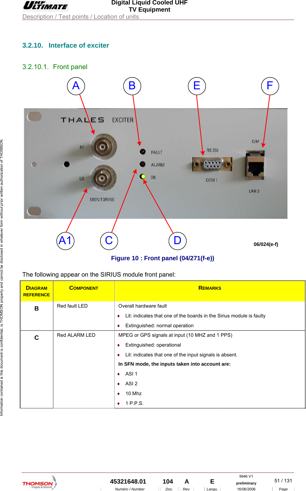
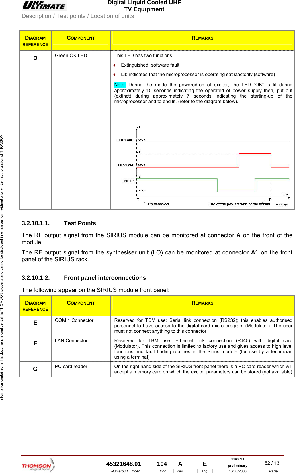
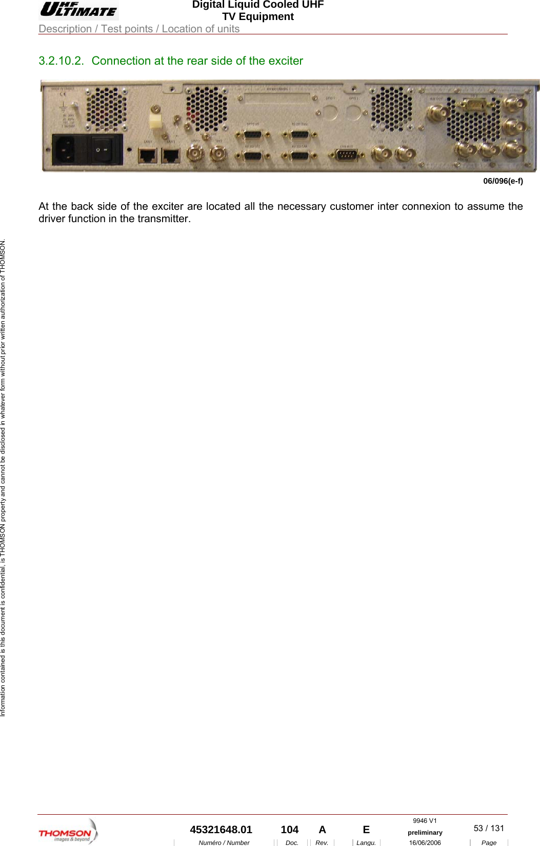
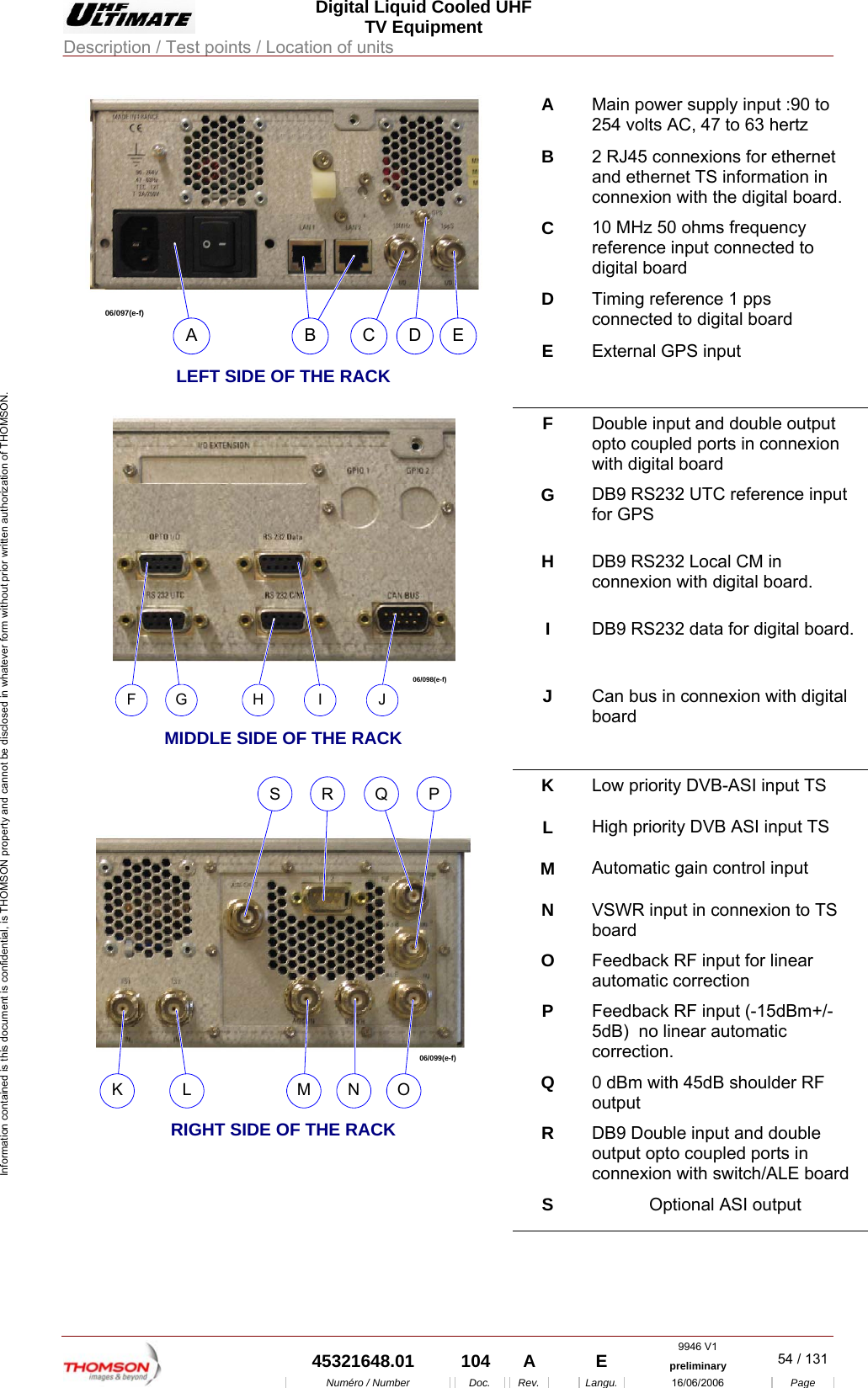
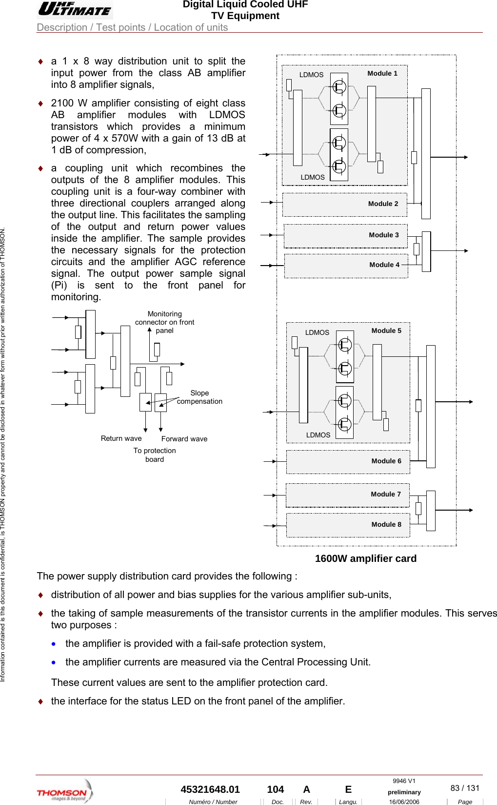
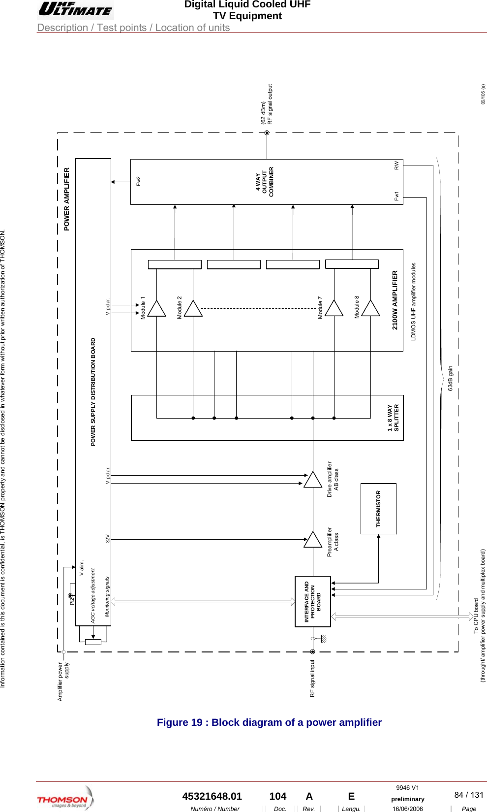
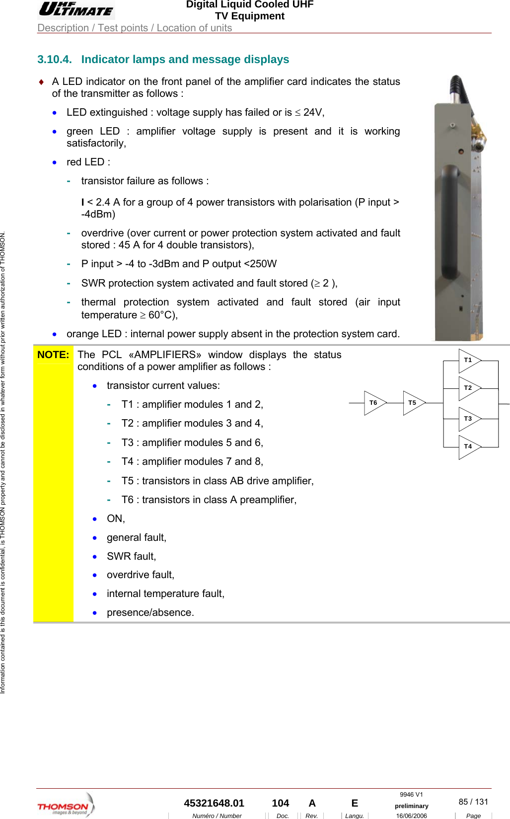
Operation manual part 2

 Digital Liquid Cooled UHF TV Equipment Description / Test points / Location of units  9946 V1  45321648.01  104  A    E  preliminary  43 / 131Numéro / Number Doc. Rev. Langu. 16/06/2006 Page Information contained is this document is confidential, is THOMSON property and cannot be disclosed in whatever form without prior written authorization of THOMSON. 3.2.3.1. Digital board Topography ref.1 ♦  This version is designed upon FPGA hardware and is dedicated to MediaFLO. ♦  The serial incoming data stream signal is processed by the channel encoder, which provides an output complex digital signal in the form of  parallel I and Q digital signals and a clock reference. ♦  The channel encoder has a hardware version allowing to perform MediaFLO modulation. ♦  The equipment can support redundant switching input for MediaFLO operation. The equipment will also be able to manage SFN operation.  ♦  An embedded microprocessor will manage daughter boards such as GPS (optional) OEM receiver, and TS Board. ♦  RS232, I2C and SPI buses are used for internal control and monitoring of the daughter boards. ♦  External Control and Monitoring is done through RS232 and/or Ethernet  and/or CAN bus. ♦  The digital board is distributing pilot clocks to SIRIUS boards. 10MHz to the synthesizer and TS board and system clock to the TS board. 3.2.3.2. TS board Topography ref.2 ♦  The  TS board received from the digital board the outputs I&Q signals and clock reference. These I&Q signals are processed by the TS board which includes : Clipping, Linear Equalization, Non Linear adaptive pre-correction.  ♦  The Clipping function limits the magnitude of the vector above a given threshold. The magnitudes higher than the threshold are replaced by the threshold complex value. ♦  The non linear automatic pre-correction function computes the best shoulder level at the output of the transmitter. The process is based on a LUT (Look Up Table) that is loaded from an iterative measurement of the shoulder level. The complex base band outputs of the LUT is then up-converted to the IF frequency. ♦  The complex IF frequency signals are converted in the analog domain, filtered,(Rep. 4) transposed  and amplified to UHF band  (Rep. 6 and 7)  ♦  Tx Board (Rep. 3) A daughter board is fitted on the TS board in order to do the up conversion function. External feedback which is coming from the RF signal at the output of the transmitter is used in order to control the shoulder, the linear correction process. ♦  Feedback signals are then processed by the TS board via the switch/ALE card (Rep. 5) achieves an automatic change over from the both signals (ALE-IN and FDB-IN) to the TS card input.  3.2.3.3. Power supply Topography ref.8 and 8A ♦  A  specific power supply is used for the whole cabinet to supply +12volts, -12 volts, +5 volts and + 3,3 volts.
 Digital Liquid Cooled UHF TV Equipment Description / Test points / Location of units  9946 V1  45321648.01  104  A    E  preliminary  44 / 131Numéro / Number Doc. Rev. Langu. 16/06/2006 Page Information contained is this document is confidential, is THOMSON property and cannot be disclosed in whatever form without prior written authorization of THOMSON. 3.2.3.4. Synthesizer  Topography ref.7 ♦  A digital programmable synthesizer is provided to deliver a sinusoidal signal at the transmitting frequency between 430 and 900 MHz with an output level of 10 dBm / 50 ohms. 3.2.3.5. GPS receiver Topography ref.12 ♦  This low power miniature board GPS enable to get the 1 pps signal 10 µs pulse, UTC, 10 MHz. 3.2.3.6. Miscellaneous The frame of the exciter included one complementary device : ♦  An LED board for front panel indications. ( Rep. 3) 3.2.3.7. Input processing 3.2.3.7.1. SFN System For the SFN network the input module plays another role. Stuffing locally is just not possible, as all transmitters have to radiate the same information at the same time. A transport stream that supports SFN differs from the MFN transport stream by including the pps and flo frames data signal. The Mega frame structure corresponds to 8 COFDM frames in the 8k mode, 16 frames in 4k mode. The SFN input module must be able to receive external synchronizaton signals, frequency reference and timing signals from a common reference, e.g. a GPS signals. 3.2.3.8.  Control of timing In an SFN application, the control of timing from input to output of the COFDM exciter is extremely important, like the ability of the COFDM exciter to synchronize in frequency and time to an external reference.
 Digital Liquid Cooled UHF TV Equipment Description / Test points / Location of units  9946 V1  45321648.01  104  A    E  preliminary  45 / 131Numéro / Number Doc. Rev. Langu. 16/06/2006 Page Information contained is this document is confidential, is THOMSON property and cannot be disclosed in whatever form without prior written authorization of THOMSON. 3.2.4. Encoding ♦  Network  :  SFN ♦  Channelization : 6MHz  ♦  Transmission modes : 12 ♦  Local network and Wide network supported ♦  MediaFloTM Logical Channel supported
 Digital Liquid Cooled UHF TV Equipment Description / Test points / Location of units  9946 V1  45321648.01  104  A    E  preliminary  46 / 131Numéro / Number Doc. Rev. Langu. 16/06/2006 Page Information contained is this document is confidential, is THOMSON property and cannot be disclosed in whatever form without prior written authorization of THOMSON. 3.2.5. Transport Stream Inputs The Sirius is provided with two serial (ASI) inputs. The active input is selected either via the front panel or the remote control. The input accepts an MPEG transport stream according to the MPEG and MediaFLo recommendations. Both 188 and 204 byte transport packets are supported.
 Digital Liquid Cooled UHF TV Equipment Description / Test points / Location of units  9946 V1  45321648.01  104  A    E  preliminary  47 / 131Numéro / Number Doc. Rev. Langu. 16/06/2006 Page Information contained is this document is confidential, is THOMSON property and cannot be disclosed in whatever form without prior written authorization of THOMSON. 3.2.6.  Adaptive non linear pre-correction The adaptive precorrection algorithm computes automatically the amplitude distribution from the non linear feedback input. Both “one shot” and “adaptive” mechanisms are available. In adaptive mode, when shoulders after power amplification are above a threshold, the exciter computes new set of coefficients. This system allows the best optimisation of the shoulder and MER after the transmitter (estimated to be 1dB better than manual adjustment). Moreover, the algorithm balances the shoulder to have the best output performance.
 Digital Liquid Cooled UHF TV Equipment Description / Test points / Location of units  9946 V1  45321648.01  104  A    E  preliminary  48 / 131Numéro / Number Doc. Rev. Langu. 16/06/2006 Page Information contained is this document is confidential, is THOMSON property and cannot be disclosed in whatever form without prior written authorization of THOMSON. 3.2.7.  Adaptive linear correction The adaptive linear correction function allows to compute a digital 64-tap filter to compensate combiner filter. The 64-tap linear corrector allows to compensate typical 12 pole elliptic filter (typ. tilt 6dB and typ. Group delay 2.5uS).
 Digital Liquid Cooled UHF TV Equipment Description / Test points / Location of units  9946 V1  45321648.01  104  A    E  preliminary  49 / 131Numéro / Number Doc. Rev. Langu. 16/06/2006 Page Information contained is this document is confidential, is THOMSON property and cannot be disclosed in whatever form without prior written authorization of THOMSON. 3.2.8. Alarm circuits A RS232 connector allows to have 2 isolated inputs and two isolated outputs. In typical application, when the exciter is sued to control amplifier system, these inputs can be used as GO/NO GO in case of amplification failure.  The two outputs can be used also to reset the power amplification system or to trig other equipment.
 Digital Liquid Cooled UHF TV Equipment Description / Test points / Location of units  9946 V1  45321648.01  104  A    E  preliminary  50 / 131Numéro / Number Doc. Rev. Langu. 16/06/2006 Page Information contained is this document is confidential, is THOMSON property and cannot be disclosed in whatever form without prior written authorization of THOMSON. 3.2.9. Frequency references The  exciter is equipped with an internal frequency reference with stability of ± 4ppm, adequate for many applications including multi frequency applications.  The user can either use the internal GPS receiver or an external GPS reference. The smart engine is designed to avoid any frequency jump at RF output. The frequency reference can either be the internal GPS or external 1pps signal or external 10MHz. When SFN is used, the pps signal is mandatory during the initialization phase.
 Digital Liquid Cooled UHF TV Equipment Description / Test points / Location of units  9946 V1  45321648.01  104  A    E  preliminary  51 / 131Numéro / Number Doc. Rev. Langu. 16/06/2006 Page Information contained is this document is confidential, is THOMSON property and cannot be disclosed in whatever form without prior written authorization of THOMSON. 3.2.10.  Interface of exciter 3.2.10.1. Front panel A B FCA1ED06/024(e-f)  Figure 10 : Front panel (04/271(f-e)) The following appear on the SIRIUS module front panel: DIAGRAM REFERENCE COMPONENT  REMARKS B  Red fault LED  Overall hardware fault ♦  Lit: indicates that one of the boards in the Sirius module is faulty ♦  Extinguished: normal operation C  Red ALARM LED   MPEG or GPS signals at input (10 MHZ and 1 PPS) ♦  Extinguished: operational ♦  Lit: indicates that one of the input signals is absent. In SFN mode, the inputs taken into account are: ♦  ASI 1 ♦  ASI 2 ♦  10 Mhz ♦  1 P.P.S.
 Digital Liquid Cooled UHF TV Equipment Description / Test points / Location of units  9946 V1  45321648.01  104  A    E  preliminary  52 / 131Numéro / Number Doc. Rev. Langu. 16/06/2006 Page Information contained is this document is confidential, is THOMSON property and cannot be disclosed in whatever form without prior written authorization of THOMSON. DIAGRAM REFERENCE COMPONENT  REMARKS D  Green OK LED  This LED has two functions:  ♦  Extinguished: software fault ♦  Lit: indicates that the microprocessor is operating satisfactorily (software) Note: During the made the powered-on of exciter, the LED “OK” is lit during approximately 15 seconds indicating the operated of power supply then, put out (extinct) during approximately 7 seconds indicating the starting-up of the microprocessor and to end lit. (refer to the diagram below).   3.2.10.1.1. Test Points The RF output signal from the SIRIUS module can be monitored at connector A on the front of the module. The RF output signal from the synthesiser unit (LO) can be monitored at connector A1 on the front panel of the SIRIUS rack. 3.2.10.1.2.  Front panel interconnections The following appear on the SIRIUS module front panel: DIAGRAM REFERENCE COMPONENT  REMARKS E  COM 1 Connector  Reserved for TBM use: Serial link connection (RS232); this enables authorised personnel to have access to the digital card micro program (Modulator). The user must not connect anything to this connector. F  LAN Connector  Reserved for TBM use: Ethernet link connection (RJ45) with digital card (Modulator). This connection is limited to factory use and gives access to high level functions and fault finding routines in the Sirius module (for use by a technician using a terminal) G  PC card reader  On the right hand side of the SIRIUS front panel there is a PC card reader which will accept a memory card on which the exciter parameters can be stored (not available)
 Digital Liquid Cooled UHF TV Equipment Description / Test points / Location of units  9946 V1  45321648.01  104  A    E  preliminary  53 / 131Numéro / Number Doc. Rev. Langu. 16/06/2006 Page Information contained is this document is confidential, is THOMSON property and cannot be disclosed in whatever form without prior written authorization of THOMSON. 3.2.10.2.  Connection at the rear side of the exciter 06/096(e-f)  At the back side of the exciter are located all the necessary customer inter connexion to assume the driver function in the transmitter.
 Digital Liquid Cooled UHF TV Equipment Description / Test points / Location of units  9946 V1  45321648.01  104  A    E  preliminary  54 / 131Numéro / Number Doc. Rev. Langu. 16/06/2006 Page Information contained is this document is confidential, is THOMSON property and cannot be disclosed in whatever form without prior written authorization of THOMSON. A  Main power supply input :90 to 254 volts AC, 47 to 63 hertz B  2 RJ45 connexions for ethernet and ethernet TS information in connexion with the digital board. C  10 MHz 50 ohms frequency reference input connected to digital board D  Timing reference 1 pps  connected to digital board 06/097(e-f)ABCDE LEFT SIDE OF THE RACK E  External GPS input F  Double input and double output opto coupled ports in connexion with digital board G  DB9 RS232 UTC reference input for GPS H  DB9 RS232 Local CM in connexion with digital board. I  DB9 RS232 data for digital board. 06/098(e-f)FGHIJ  MIDDLE SIDE OF THE RACK J  Can bus in connexion with digital board K  Low priority DVB-ASI input TS L  High priority DVB ASI input TS M  Automatic gain control input N  VSWR input in connexion to TS board O  Feedback RF input for linear automatic correction P  Feedback RF input (-15dBm+/-5dB)  no linear automatic correction. Q  0 dBm with 45dB shoulder RF output R  DB9 Double input and double output opto coupled ports in connexion with switch/ALE board 06/099(e-f)KLMNOPQRS RIGHT SIDE OF THE RACK S  Optional ASI output
 Digital Liquid Cooled UHF TV Equipment Description / Test points / Location of units  9946 V1  45321648.01  104  A    E  preliminary  55 / 131Numéro / Number Doc. Rev. Langu. 16/06/2006 Page Information contained is this document is confidential, is THOMSON property and cannot be disclosed in whatever form without prior written authorization of THOMSON. 3.2.11. General characteristics 3.2.11.1. Pre-correction The pre-corrector option supports non-linear pre-correction (gain and phases vs power level) and linear pre-correction (level and group delay response vs. frequency). The pre-corrector allows further control of the peak power clip level (range  + 17dB to +7dB peak power relative to average RMS level). Non-linear correction: ♦  Gain correction: Max 12dB, subject to available headroom ♦  Phase correction: -6 to +30 degrees, subject to available headroom Linear correction: ♦  Correction points: 64 ♦  Point spacing: 1/20 of nominal spectrum BW ♦  Amplitude correction: ±10dB ♦  Amplitude resolution: 0.01dB ♦  Group delay correction: ±2000ns ♦  Group delay resolution: 1ns 3.2.11.2.  General Electrical Mechanical and Cooling Characteristics Rack :  19” 1U desired, 2U max, depth 600 <mm Main Consumption :  < 200 VA Cooling :  Internal fan, air input on the front panel Finish :  THALES standard
 Digital Liquid Cooled UHF TV Equipment Description / Test points / Location of units  9946 V1  45321648.01  104  A    E  preliminary  56 / 131Numéro / Number Doc. Rev. Langu. 16/06/2006 Page Information contained is this document is confidential, is THOMSON property and cannot be disclosed in whatever form without prior written authorization of THOMSON. 3.3.  SIRIUS cooling assembly 3.3.1.  Data sheet - Fans : 91835299
 Digital Liquid Cooled UHF TV Equipment Description / Test points / Location of units  9946 V1  45321648.01  104  A    E  preliminary  57 / 131Numéro / Number Doc. Rev. Langu. 16/06/2006 Page Information contained is this document is confidential, is THOMSON property and cannot be disclosed in whatever form without prior written authorization of THOMSON.
 Digital Liquid Cooled UHF TV Equipment Description / Test points / Location of units  9946 V1  45321648.01  104  A    E  preliminary  58 / 131Numéro / Number Doc. Rev. Langu. 16/06/2006 Page Information contained is this document is confidential, is THOMSON property and cannot be disclosed in whatever form without prior written authorization of THOMSON. 3.3.2.  Data sheet – Power Supply : 91851992
 Digital Liquid Cooled UHF TV Equipment Description / Test points / Location of units  9946 V1  45321648.01  104  A    E  preliminary  59 / 131Numéro / Number Doc. Rev. Langu. 16/06/2006 Page Information contained is this document is confidential, is THOMSON property and cannot be disclosed in whatever form without prior written authorization of THOMSON. 3.4. Transmitter Management rack DD 45323663.02 06-85A (e-f)PS1 PS2A1A2*A2ITEMA2A2*PS1PS2DESIGNATIONCarte CPU (TH860)Carte interconnexion CPU/EMB/PAAlimentation 1 (+5V, ±12V, +24V)Alimentation 2 (+5V, ±12V, +24V)DESIGNATIONCPU board (TH860)Management system interconnection  board, CPU/EXCITER/PAPower supply 1 (+5V, ±12V, +24V)Power supply 2 (+5V, ±12V, +24V)Figure 11 .Management rack
 Digital Liquid Cooled UHF TV Equipment Description / Test points / Location of units  9946 V1  45321648.01  104  A    E  preliminary  60 / 131Numéro / Number Doc. Rev. Langu. 16/06/2006 Page Information contained is this document is confidential, is THOMSON property and cannot be disclosed in whatever form without prior written authorization of THOMSON. ITEMA2J1J2W10DESIGNATIONCarte interconnexion gestion, CPU/EMB/PAEntrée secteur de l'alimentation 1 CPU/PS1Entrée Ethernet RJ45DESIGNATIONManagement system interconnection board,CPU /EXCITER/PAMains input CPU/PS1 power supply unit 1Input Supervision RJ45Entrée secteur de l'alimentation 2 Ecran/PS2 Mains input Screen/PS2 power supply unit 2J2 J1A2 W1006/094(e-f)  Figure 12  : Pre-equipped box
 Digital Liquid Cooled UHF TV Equipment Description / Test points / Location of units  9946 V1  45321648.01  104  A    E  preliminary  61 / 131Numéro / Number Doc. Rev. Langu. 16/06/2006 Page Information contained is this document is confidential, is THOMSON property and cannot be disclosed in whatever form without prior written authorization of THOMSON.             3.5.  Interconnections Board EMB/UC TX Numerique 45324511 3.5.1. Outline In addition to housing the transmitter CPU card, this card also acts as an interface between the CPU card and the other transmitter equipment. The exciter/CPU interconnection card is an essential part of the transmitter; it provides for the following: ♦  interconnections for DC, analogue signals and logic data between the exciter(s) and the control system (Central Processing Unit), ♦  interconnections between the Central Processing Unit (CPU) card and the rest of the transmitter, ♦  interconnections between the Central Processing Unit card on the one hand and the user interfaces (PCL and remote user interface) together with equipment with connections with systems external to the transmitter (GPS, modem) on the other, ♦  exciter changeover switching operations. 3.5.1.1.  Architecture and operational description The exciter/CPU interconnection card consists of a mother board and a daughter board. It houses the CPU card and the following: ♦  internal data buses which provide for data exchange between the various card connectors, ♦  connectors for signal and data interchange with : •  the MODAP unit, •  the RF switcher (Double Drive transmitter), •  the multiplex card, •  the user interfaces, •  external units, ♦  connections between the various card connectors, ♦  connections used to distribute the supply voltages from the very low voltage power supply card of the Central processing unit to: •  the Central Processing Unit card, •  the Local Control Panel (PCL), For the most part the mother board contains the connections with the MODAP unit and the daughter board contains the connections with the rest of the transmitter. 3.5.2.  Protection and surveillance devices The exciter/CPU interconnection card has no need of internal protection and surveillance devices; nevertheless it incorporates protection devices for the power supplies which feed: ♦  the logic system, ♦  the PCL, ♦  the multiplex card.
 Digital Liquid Cooled UHF TV Equipment Description / Test points / Location of units  9946 V1  45321648.01  104  A    E  preliminary  62 / 131Numéro / Number Doc. Rev. Langu. 16/06/2006 Page Information contained is this document is confidential, is THOMSON property and cannot be disclosed in whatever form without prior written authorization of THOMSON. These fuses go open circuit in over-current conditions and reset automatically; they cannot be changed on line. Fuses on the mother board PROTECTIVE DEVICE POWER SUPPLY SOURCE  DESTINATION F1  +5 V CPU power supply card  MODAP logic system F2  +12 V CPU power supply card  Multiplex card  Fuses on the daughter board PROTECTIVE DEVICE POWER SUPPLY SOURCE  DESTINATION F1  +5 V CPU power supply card  PCL F2  +12 V exciter A power supply card  PCL F3  -12 V exciter A power supply card  Multiplex card F4  +12 V exciter B power supply card  PCL F5  -12 V exciter B power supply card  Multiplex card F6  +24 V CPU power supply card  PCL F7  +24 V CPU power supply card   F8  -12 V exciter A + B power supply card  Provisional F9  +12 V exciter A power supply card  Provisional F10  +12 V exciter B power supply card  Provisional F11  -12 V exciter A power supply card  PCL F12  -12 V exciter B power supply card  PCL  3.5.3.  Indicator lamps and message displays Since this card is only concerned with interconnections, it does not have any indicator lamps or operational status indicators. 3.5.4. Controls The transmitter configuration can be controlled by override switches mounted on the exciter/CPU interconnection card mother board as follows : ♦  SW1 : switches the transmitter to installation mode, ♦  SW2 : switches the transmitter on if the CPU is faulty or not present, ♦  SW3 : switches the transmitter off if the CPU is faulty or not present, ♦  SW4 : switches exciter A to air if the CPU is faulty or not present, ♦  SW5 : switches exciter B to air if the CPU is faulty or not present. 3.5.5. Power input Since this card is only concerned with interconnections, it does not have any need for a power supply. The few internal components which need power use the voltage supplies from the exciter and CPU power supply cards.
 Digital Liquid Cooled UHF TV Equipment Description / Test points / Location of units  9946 V1  45321648.01  104  A    E  preliminary  63 / 131Numéro / Number Doc. Rev. Langu. 16/06/2006 Page Information contained is this document is confidential, is THOMSON property and cannot be disclosed in whatever form without prior written authorization of THOMSON. 3.5.6.  Connections and data transfer The mother board connectors are as follows: ♦  on one side : connectors J6, J12, J20, J21 to the CPU, ♦  on the other side: •  J6.1, J12.1, J20.1, J21.1: to the daughter board, •  J13 :   connection to a GPS receiver (option) which provides sync signals for the modulator, •  J30 :  connects the CPU with the exciter RF switching relays, •  J40 :  connects to remote user interface via RS232 serial link, •  J50 :   connects CPU to exciter A, •  J70 :   connects CPU to external DVB -T modulator (exciter A), •  J80 :  connects CPU or exciter A to external equipment via RS232 or RS485    serial link (provisional), •  J90 :  connects CPU to external DVB -T modulator (exciter B), •  J100 :  connects CPU or exciter B to external equipment via RS232 or RS485    serial link (provisional), •  J150 :   connects CPU to exciter B. The daughter board connectors are as follows: ♦  on one side : connectors J6, J12, J20, J21 to the mother board, ♦  on the other face it has the following connectors for connections with the rest of the transmitter : •  J1, for input command signals from a hard wired remote user interface to the Central Processing Unit card, •  J2, J3, for output status signals from the Central Processing Unit card to a hard wired remote user interface, •  J4, for the transfer of command signals, in addition to status and fault signals between the various transmitter units (other than the exciter and CPU) and the multiplex card, •  J5, for the input of messages from the multiplex card about faults in the various transmitter units (other than the exciter and CPU), •  J7, for data exchange with the PCL and for feeding very low voltage supplies to the PCL, •  J8, not used, •  J9, for the input of very low voltage supplies from the CPU power supply card, •  J10 •  J11, for connections via the serial link between the CPU and a remote user interface (RS232 with JBUS protocol). 3.5.7. Cooling The exciter/CPU interconnection card is cooled by natural convection.
 Digital Liquid Cooled UHF TV Equipment Description / Test points / Location of units  9946 V1  45321648.01  104  A    E  preliminary  64 / 131Numéro / Number Doc. Rev. Langu. 16/06/2006 Page Information contained is this document is confidential, is THOMSON property and cannot be disclosed in whatever form without prior written authorization of THOMSON. 3.5.8. Transportability No special requirements. 04/03604/035 Figure 13 : Connection card Management/SIRIUS (2 faces)
 Digital Liquid Cooled UHF TV Equipment Description / Test points / Location of units  9946 V1  45321648.01  104  A    E  preliminary  65 / 131Numéro / Number Doc. Rev. Langu. 16/06/2006 Page Information contained is this document is confidential, is THOMSON property and cannot be disclosed in whatever form without prior written authorization of THOMSON.             3.6.  Preamplifier RF Unit 45326079 3.6.1. Presentation NOTE :  The preamplifier Module is “Hot Swap” compatible. Defective PA Modules may be removed and replaced without shutting the entire transmitter system down. The RF preamplifier is designed to amplify residual side band modulated television analogue signals for all standards, and digital signals in DTV (US - ATSC standard and Europe - DVB-T standard). It is designed to work in UHF transmitters for bands IV and V. The preamplifier output power is approximately 0,8 W peak at 1 dB of compression with an minimum gain of 20 dB. The preamplifier is fully solid-state (Hybrid technology). The module is fitted with an the interface connector SUB-D (type B3W13) for 240V AC mains input, for output of fault data used by the transmitter control system and for RF connectors. One small Handle is used to insert and remove the preamplifier module. 3.6.2. Architecture The RF preamplifier consists of the following parts : ♦  A printed circuit board including : •  class A amplifier, •  an output coupling stage, •  the peak detector circuit and RF monitoring, •  an integrated power supply unit. ♦  Heat sink  ♦  Protection cover Figure below shows the positions of the various parts in the preamplifier. Handle PSU (AC/DC) DC/DC ConverterF1Fuse RFAmplifier04/040 (e)SUB-DConnector Figure 14 : UHF preamplifier
 Digital Liquid Cooled UHF TV Equipment Description / Test points / Location of units  9946 V1  45321648.01  104  A    E  preliminary  66 / 131Numéro / Number Doc. Rev. Langu. 16/06/2006 Page Information contained is this document is confidential, is THOMSON property and cannot be disclosed in whatever form without prior written authorization of THOMSON. 3.6.3. Operational description The input RF signal passes through the following stages. ♦  A class A preamplifier to deliver a rms power of 0.8 W. ♦  An output coupling stage, with a slope correction circuit and which sends an RF feedback signal to: •  the peak detector circuit (provides the status of the preamplifier), •  which the latter then sends out from RF monitoring outputs to the pre-amplifier. The built-in power supply G1 provides 24 V used to bias the hybrid amplifier MA1 and equally to feed the DC/DC converter MA3. It supply the buffer circuit MA2 of the peak detector CR1. The power supply G1 is protected by fuse F1 from short-circuits.  A1Entrée RFRF input Sortie RFRF outputA2Sortie test RFRF test outputA3CR1Sortie détectionDetection outputMA2G1DC/DCMA35V-DCF124V-DCEntrée secteurMains inputAlimentationPower supply04/030 (f-e)ACMA1 Figure 15 : Block diagram of the preamplifier 3.6.4.  Indicator lamps and message displays The RF preamplifier does not have any indicator lamps or operational status indicators. NOTE :  The PCL «EXCITER» window displays the status condition of a preamplifier. 3.6.5. Test points Connector A2 on the rear of the panel provides a test point monitoring feed of the preamplifier RF output signal. The level of the monitoring feed is 20 dB down on the output signal to the power amplifier unit.
 Digital Liquid Cooled UHF TV Equipment Description / Test points / Location of units  9946 V1  45321648.01  104  A    E  preliminary  67 / 131Numéro / Number Doc. Rev. Langu. 16/06/2006 Page Information contained is this document is confidential, is THOMSON property and cannot be disclosed in whatever form without prior written authorization of THOMSON. 3.6.6. Adjustment controls The pre-amplifier has no controls on its front and rear panels. 3.6.7.  Protection and surveillance devices The RF preamplifier module is fused by an CMS fuse F1 (1A) at the +24VDC input. 3.6.8. Power input The RF preamplifier gets its single phase mains feed from the mains distribution panel. The mains input connector is fed from connector J10 or J11 on the EXCITER/CPU interconnection board in bottom of the transmitter control system frame. 3.6.9. Connections The RF preamplifier module has one SUB-D connector (Type B 3W13) on its rear panel as follows: •  A1  : RF input.   •  A2  : RF monitoring.   •  A3  : RF output.   •  Pins 1 & 6  :  240 V AC Neutral.•  Pins 8 & 3  :  240 V AC Phase.   •  Pin 5   Detection output.  •  Pins 7 & 2  : GND.   A1 A3A204/038   3.6.10. Cooling The preamplifier module could be cooled by natural convection. 3.6.11. Transportability No special requirements.
 Digital Liquid Cooled UHF TV Equipment Description / Test points / Location of units  9946 V1  45321648.01  104  A    E  preliminary  68 / 131Numéro / Number Doc. Rev. Langu. 16/06/2006 Page Information contained is this document is confidential, is THOMSON property and cannot be disclosed in whatever form without prior written authorization of THOMSON. 3.6.12. Environmental Conditions Guaranteed specifications (alt≤1500m) :  0 à 55°C. Guaranteed operation :  -10 à 60°C. Storage temperature :  -30 à 60°C. Relative humidity :  95 % without condensation. 3.6.13. Mechanical Characteristics size including handle and connector (W x H x D) :  230x60x70 mm. weight :  0.8 kg max 3.6.14. Electrical Characteristics The electrical characteristics below are given for above environmental conditions. Input max. level without destruction:  20 dBm max. Output power (1 dB compression on VSWR ≤ 1.2 and 470 ≤ F ≤ 862 MHz):  0.8 W min. Instantaneous bandwidth:  470 à 862 MHz. Gain in bandwidth:  21 dB ± 1 dB. Gain linear distortions in 470 à 862 MHz for 20 dBm:  ± 0.75 dB max. Input matching in bandwidth:  10 dB min. Output matching in bandwidth:  10 dB min. Shoulders for Ps = 100 mW rms:  - 40 dBc min. Mains power supply:  240 Volts AC.
 Digital Liquid Cooled UHF TV Equipment Description / Test points / Location of units  9946 V1  45321648.01  104  A    E  preliminary  69 / 131Numéro / Number Doc. Rev. Langu. 16/06/2006 Page Information contained is this document is confidential, is THOMSON property and cannot be disclosed in whatever form without prior written authorization of THOMSON.             3.7.  Central Processing Unit (CPU-TH860) 3.7.1. Outline NOTA :  The SNMP protocol is described in Annexes. The Central Processing Unit supervises the running of the transmitter; its principal functions are as follows : ♦  to monitor and control the various units in the transmitter, ♦  to store the faults in these units together with dates and times, ♦  to control the various interfaces in conjunction with a local or remote operator. 3.7.2. Architecture The Central Processing Unit is on a double Euro card and contains : ♦  the Central Processing Unit, ♦  an EPROM memory, ♦  an SRAM memory, ♦  a connector for PCMCIA card, ♦  a flash EPROM memory, ♦  4 timers, ♦  a time and date clock, ♦  an internal configuration port containing 7 jumper straps which can be read by a micro controller, ♦  on/off inputs/outputs, ♦  RS 232 serial link connectors, ♦  one analogue input, ♦  One Ethernet input. 3.7.3.  Protection and surveillance devices The Central Processing Unit has a unit for monitoring the +5 V supply. During switch-on and switch-off the output buffers wait for their confirmation command from the micro controller before exchanging data with the external system. These output buffers are disabled as soon as the +5 V voltage supply rail drops below 4.5 V.
 Digital Liquid Cooled UHF TV Equipment Description / Test points / Location of units  9946 V1  45321648.01  104  A    E  preliminary  70 / 131Numéro / Number Doc. Rev. Langu. 16/06/2006 Page Information contained is this document is confidential, is THOMSON property and cannot be disclosed in whatever form without prior written authorization of THOMSON.  Figure 16 : CPU board – TH860 3.7.4.  Indicator lamps and message displays The Central Processing Unit card has the following on its front panel : ♦  a green indicator lamp : when this flashes the memory access is operating satisfactorily, ♦  an orange/yellow indicator lamp: when this is lit up the CPU card is powered, ♦  an red indicator lamp: when this is lit up CPU board is not operating properly (light up a short time during CPU start up). yellow LEDred LEDGreen LEDswitch not usedEthernet connectionRJ45 P1Location for PCMCIA cardP2P3CPU Reset 3.7.5. Controls The switch on the CPU front panel is not used. 3.7.6. Power input The Central Processing Unit card is powered by +5 V and +12 V DC from the CPU power supply card in the front of the transmitter.
 Digital Liquid Cooled UHF TV Equipment Description / Test points / Location of units  9946 V1  45321648.01  104  A    E  preliminary  71 / 131Numéro / Number Doc. Rev. Langu. 16/06/2006 Page Information contained is this document is confidential, is THOMSON property and cannot be disclosed in whatever form without prior written authorization of THOMSON. 3.7.7.  Connections and data transfer The Central Processing Unit has the following connectors: On front panel : ♦  connector P1 : spare, ♦  connector P2 : for serial link (RS 232C) connection with the "Log book" terminal, ♦  connector P3 : spare, ♦  Connector P5: for Ethernet network, P1Location for PCMCIA cardP2P3CPU Reset In the rear panel, the following connectors plug into the exciter/CPU interconnection card : ♦  connector J6 which has : •  the following outputs : -  command signals from the hard wired remote user interface (via connector J1 on the interconnection card), -  command to RF relay for switching between exciter A and exciter B, situated on the exciter/CPU interconnection card, -  the synthesizer reset command, -  RF switching commands, -  the on/off command for the amplifier power supplies (via interconnection card). •  the following inputs : -  values for the vision, sound and antenna RF power levels sent from the RF probes (via the PCL and connector J7 of the interconnection card), -  the +5 V supply from the CPU power supply card (via interconnection card), •  the bus connections to the multiplex card, ♦  connector J20 which has : •  the following outputs : -  commands to the PCL indicator lamps (via connector J7 of the interconnection card), -  RF switching commands, •  the following inputs : -  commands from the PCL (via connector J7 of the interconnection card), -  presence signals from the exciters, -  the +12 V supply from the CPU power supply card (via interconnection card), •  connections to the PCL data bus (bus RS 232), (via connector J7 of the interconnection card),
 Digital Liquid Cooled UHF TV Equipment Description / Test points / Location of units  9946 V1  45321648.01  104  A    E  preliminary  72 / 131Numéro / Number Doc. Rev. Langu. 16/06/2006 Page Information contained is this document is confidential, is THOMSON property and cannot be disclosed in whatever form without prior written authorization of THOMSON. •  connections via the data bus with MODAP A, (via connector J50 of the interconnection card), •  connections to the remote user interface data bus (RS 232 bus), (via connectors J11 or J40 of the interconnection card), •  connections to the data bus to the synthesizers (via connector J50 of the interconnection card), ♦  connector J21 : •  for output status signals to a hard wired remote user interface (via connectors J2 and J3 of the interconnection card), ♦  connector P6 which has : •  connections via the data bus with MODAP B, (via connector J150 of the interconnection card), •  connections via the data bus with external equipment using RS 232 or RS 485 serial links (via connectors J70, J80, J90, J100 of the interconnection card). 3.7.8. Cooling The Central Processing Unit is cooled by the exciter cooling system. Input air is drawn into the cooling chamber which is situated below the frame which houses the exciter cards ; the air then circulates through the cards.
 Digital Liquid Cooled UHF TV Equipment Description / Test points / Location of units  9946 V1  45321648.01  104  A    E  preliminary  73 / 131Numéro / Number Doc. Rev. Langu. 16/06/2006 Page Information contained is this document is confidential, is THOMSON property and cannot be disclosed in whatever form without prior written authorization of THOMSON.             3.8.  Power supply unit for UC/Multiplex/PCL 61390563
 Digital Liquid Cooled UHF TV Equipment Description / Test points / Location of units  9946 V1  45321648.01  104  A    E  preliminary  74 / 131Numéro / Number Doc. Rev. Langu. 16/06/2006 Page Information contained is this document is confidential, is THOMSON property and cannot be disclosed in whatever form without prior written authorization of THOMSON.
 Digital Liquid Cooled UHF TV Equipment Description / Test points / Location of units  9946 V1  45321648.01  104  A    E  preliminary  75 / 131Numéro / Number Doc. Rev. Langu. 16/06/2006 Page Information contained is this document is confidential, is THOMSON property and cannot be disclosed in whatever form without prior written authorization of THOMSON.             3.9.  Control panel (PCL) 45333047 3.9.1. Architecture The Local Control Panel (PCL) consists of two units: ♦  an LCD touch screen, ♦  a display circuit. It is the principal user interface for the transmitter. It gives the operator the facilities to display the various status conditions of the  transmitter and its main sub-units.    3.9.2.  Architecture and operational description There are three push buttons on the PCL (On, Off, Reset). Each command signal from a push button is: ♦  fed to a set-reset latch circuit to avoid contact bounce; then, ♦  shaped into a pulse via a timer; and finally,  ♦  sent to a buffer memory which transmits the data pulses to the control system of the transmitter (CPU card). The output power level as measured by a directive probe is displayed on an LED bargraph. A voltage which is proportional to the measured power value is applied to converters to produce a progressive illumination of the LED bargraph; an illumination of the total length of the bargraph corresponds to the nominal output power. The values for the output and reflected signals as measured by the probes are sent directly to the control system of the transmitter. The indicator lamps on the display card indicate transmitter operational status conditions and they are activated by command signals from the control system of the transmitter (CPU). An RS 232 serial link from the CPU which carries data to and from the LCD screen passes through the display card.
 Digital Liquid Cooled UHF TV Equipment Description / Test points / Location of units  9946 V1  45321648.01  104  A    E  preliminary  76 / 131Numéro / Number Doc. Rev. Langu. 16/06/2006 Page Information contained is this document is confidential, is THOMSON property and cannot be disclosed in whatever form without prior written authorization of THOMSON.              M ESUREPUISSANCEAVANT FILTREONDE RETOURBEFORE FILTERM EASUREM ENTV.S.W.RM ESUREPUISSANCEANTENNE RETOURANTENNAM EASUREM ENTV.S.W.RM ESUREPUISSANCEPOWERM EASUREM ENTGOHOM E ALARM UNL OCKUNITE CENTRALEVIA LA CARTED' INTERCONNEXI ONEM B/UCCPU BOARDTHROUGHEXCITER/CPUINTERCONNECTI ONBOARDR4 3 5R4 5 5R475Signal  allerForward signalSignal retourReturn signal Signal antenne retourReturn antenna signalON OFF RESETDétecteurs etsondes  reflectomètresDetectors andreflectometer probes99/363 (f/e) Figure 17 : Bloc diagram display card
 Digital Liquid Cooled UHF TV Equipment Description / Test points / Location of units  9946 V1  45321648.01  104  A    E  preliminary  77 / 131Numéro / Number Doc. Rev. Langu. 16/06/2006 Page Information contained is this document is confidential, is THOMSON property and cannot be disclosed in whatever form without prior written authorization of THOMSON.             3.9.3.  Indicator lamps and message displays There are no status indicator lamps to indicate the status conditions of the display card. The indicator lamps on the front of the PCL indicate the overall status of the transmitter. 3.9.4. Adjustment controls R435TESTR475 The sensitivity controls on the front of the PCL are used to set the parameters which are displayed by the bar graph on the PCL and in the "RF REFLECTED LEVEL" and "RF LEVEL" windows; these adjustments set the input signals and are as follows : ♦  R435 “POWER INDICATION” : sensitivity control for output power indication, ♦  R475 “ANTENNA VSWR” : sensitivity control for antenna SWR indication. The output power level is displayed on the bargraph. Return SWR values are displayed on the "RF REFLECTED LEVEL" window. 3.9.5. Test points Pressing on the "TEST" button on the front panel of the PCL with a pointed object will check that the indicator lamps and bargraph LED’s are working properly.
 Digital Liquid Cooled UHF TV Equipment Description / Test points / Location of units  9946 V1  45321648.01  104  A    E  preliminary  78 / 131Numéro / Number Doc. Rev. Langu. 16/06/2006 Page Information contained is this document is confidential, is THOMSON property and cannot be disclosed in whatever form without prior written authorization of THOMSON.             3.9.6.  The display card 45324176 3.9.6.1. Outline The display card performs the following functions : ♦  it sends commands to the equipment units, ♦  it demodulates the monitoring signals received from the directional probes in the RF connections to the transmitter antenna and displays them, ♦  it acts as the interface between the LCD screen and the transmitter control system. 3.9.6.2. Operational description Refer to the entitled paragraph « Operational description » of the sub-assembly LOCAL CONTROL PANEL. 3.9.6.3. Indicator lamps There are no status indicator lamps to indicate the status conditions of the display card. The indicator lamps on the front of the PCL indicate the overall status of the transmitter. 3.9.6.4.   Adjustment controls and Test et points Refer to entitled paragraphs « Adjustment controls » and « Test et points » of the sub-assembly LOCAL CONTROL PANEL. 3.9.6.5.  Internal protective devices The display card has no need of internal protective devices. 3.9.6.6.  Connections and data transfer The display card has the following connectors: ♦  Connectors for envelope signal from reflectometer probes : •  connector J1 in case of: -  analogue transmitter: for sound signal, -  digital transmitter: not used •  connector J2 in case of: -  analogue transmitter: for vision signal, -  digital transmitter: for RF signal, •  connector J3, for antenna SWR signal, •  connector J4 in case of: -  analogue transmitter: for vision SWR signal (only in case of split channel transmitter) or not used, -  digital transmitter: for SWR signal
 Digital Liquid Cooled UHF TV Equipment Description / Test points / Location of units  9946 V1  45321648.01  104  A    E  preliminary  79 / 131Numéro / Number Doc. Rev. Langu. 16/06/2006 Page Information contained is this document is confidential, is THOMSON property and cannot be disclosed in whatever form without prior written authorization of THOMSON. •  connector J5 in case of: -  analogue transmitter: for sound SWR signal (only in case of split channel transmitter) or not used, -  digital transmitter: not used ♦  Connector J6 which provides : •  the connection with the Central Processing Unit (via the exciter/CPU interconnection card) : -  the input illumination signals for PCL indicator lamps, -  the output command signals (On, Off, Reset), -  input of output and reflected power signal measurement values from the reflectometer probes. •  the connection of the RS 232 serial link for data exchange between the transmitter control system and the PCL touch screen, •  for input power supply to the PCL (display card and screen), ♦  Connector J7 for the RS 232 serial link between the display card and the touch screen (signal data originate in the CPU), ♦  Connector J8 for the +24 V DC input power for the touch screen from the exciter / CPU interconnection card, ♦  Connector J9 which is not used.  3.9.6.7.  Input power supplies The display card is fed with the following supplies: ♦  +5 V DC from the CPU power supply card via the exciter/CPU interconnection card, ♦  +12 V and -12 V DC, with back-ups, from the exciter power supply cards via the exciter/CPU interconnection card. 3.9.6.8. Cooling The display card does not require a separate cooling system; it is cooled by natural convection.
 Digital Liquid Cooled UHF TV Equipment Description / Test points / Location of units  9946 V1  45321648.01  104  A    E  preliminary  80 / 131Numéro / Number Doc. Rev. Langu. 16/06/2006 Page Information contained is this document is confidential, is THOMSON property and cannot be disclosed in whatever form without prior written authorization of THOMSON.             3.10. The power amplifier, 45323629 3.10.1. Outline The power amplifier is designed to amplify residual sideband modulated television analogue signals for all standards, and digital signals in DTV. It is designed to work in UHF transmitters for 650 to 750 MHz. The power output specification is as follows : ♦  vision : •  approximately 2100W peak power at 1 dB compression, •  960W rms power with a gain of 63 dB, ♦  vision plus sound : •  approximately 2100W peak power, ♦  peak power of 2100 W, for 570 W RMS approximately with digital signals.   3.10.2. Architecture The power amplifier consists of the following sub-units : ♦  protection card and interface, ♦  class A preamplifier, ♦  class AB drive amplifier, ♦  input splitter, 1 x 8 ways, ♦  final class AB 2100 W amplifier consisting of eight amplifier modules, ♦  4 way combiner, ♦  power supply distribution card, Figure below shows the positions of the various cards in the power amplifier.
 Digital Liquid Cooled UHF TV Equipment Description / Test points / Location of units  9946 V1  45321648.01  104  A    E  preliminary  81 / 131Numéro / Number Doc. Rev. Langu. 16/06/2006 Page Information contained is this document is confidential, is THOMSON property and cannot be disclosed in whatever form without prior written authorization of THOMSON. 06/082(e)J2RF OutputJ104RF InputPower supplyConnectorJ106 SideJ107 Side 06/083(e)External connectionsProtection & interface boardClass A preamplifier2 ways WilkinsonClass AB amplifierSplitter 8 WaysExternal connectionsPower supply distribution board4 ways combiner Printed circuit boardAGC voltage adjustmentTwo-coloured indicatorHoles to fix the specialcarrying handleHydraulicconnectorNever carryamplifierby the handleon the front panelof the amplifier.Use the specialhandleHydraulicconnectorA2A4A5A6A11A7A9A8R164DS1A5ItemA11A2A4A5A6ItemA7A8A9R164DS1  Figure 18 : UHF Amplifier 1600W
 Digital Liquid Cooled UHF TV Equipment Description / Test points / Location of units  9946 V1  45321648.01  104  A    E  preliminary  82 / 131Numéro / Number Doc. Rev. Langu. 16/06/2006 Page Information contained is this document is confidential, is THOMSON property and cannot be disclosed in whatever form without prior written authorization of THOMSON. 3.10.3. Operational description The input RF signal passes through the following stages ♦  Protection and interface card which provides the following : •  manual adjustment of gain and phase to equalise for the variations between amplifiers (internal adjustment not accessible to operator), •  generation of a voltage which is adjustable for automatic gain control (AGC) with reference to a sampling of the RF signal at the combiner unit (adjustment accessible on front panel), amplifier protection system (see § «Surveillance devices»). ♦  A class A preamplifier with LDMOS transistors to deliver a minimum power of 20 W at 0.2 dB compression, with a gain G ≥ 37 dB,    ♦  A class AB drive amplifier with LDMOS transistors to deliver a power of 220W at 1 dB compression, with a gain G ≥ 12 dB at 0.2 dB compression. 3 dB couplerLDMOS LDMOSHybridamplifier  LDMOSLDMOSLDMOSLDMOSModule 1Module 2
 Digital Liquid Cooled UHF TV Equipment Description / Test points / Location of units  9946 V1  45321648.01  104  A    E  preliminary  83 / 131Numéro / Number Doc. Rev. Langu. 16/06/2006 Page Information contained is this document is confidential, is THOMSON property and cannot be disclosed in whatever form without prior written authorization of THOMSON. ♦  a 1 x 8 way distribution unit to split the input power from the class AB amplifier into 8 amplifier signals, ♦  2100 W amplifier consisting of eight class AB amplifier modules with LDMOS transistors which provides a minimum power of 4 x 570W with a gain of 13 dB at 1 dB of compression, ♦  a coupling unit which recombines the outputs of the 8 amplifier modules. This coupling unit is a four-way combiner with three directional couplers arranged along the output line. This facilitates the sampling of the output and return power values inside the amplifier. The sample provides the necessary signals for the protection circuits and the amplifier AGC reference signal. The output power sample signal (Pi) is sent to the front panel for monitoring. Monitoringconnector on frontpanelReturn wave Forward waveTo protectionboardSlopecompensation LDMOSLDMOS Module 5Module 7Module 8Module 6Module 3Module 4LDMOSLDMOS Module 1Module 2 1600W amplifier card The power supply distribution card provides the following : ♦  distribution of all power and bias supplies for the various amplifier sub-units, ♦  the taking of sample measurements of the transistor currents in the amplifier modules. This serves two purposes : •  the amplifier is provided with a fail-safe protection system, •  the amplifier currents are measured via the Central Processing Unit. These current values are sent to the amplifier protection card. ♦  the interface for the status LED on the front panel of the amplifier.
 Digital Liquid Cooled UHF TV Equipment Description / Test points / Location of units  9946 V1  45321648.01  104  A    E  preliminary  84 / 131Numéro / Number Doc. Rev. Langu. 16/06/2006 Page Information contained is this document is confidential, is THOMSON property and cannot be disclosed in whatever form without prior written authorization of THOMSON.  Module 1Module 2Module 7Module 82100W AMPLIFIERDrive amplifierAB classPreamplifierA class(62 dBm)RF signal output1 x 8 WAYSPLITTERRF signal inputTHERMISTORTo CPU board(throught/ amplifier power supply and multiplex board)LDMOS UHF amplifier modules4 WAYOUTPUTCOMBINERAmplifier powersupplyAGC voltage adjustmentMonitoring signals 32VPi2V alim.V polar.POWER SUPPLY DISTRIBUTION BOARDPOWER AMPLIFIER63dB gainFw2Fw1 RWINTERFACE ANDPROTECTIONBOARD06/105 (e)V polar. Figure 19 : Block diagram of a power amplifier
 Digital Liquid Cooled UHF TV Equipment Description / Test points / Location of units  9946 V1  45321648.01  104  A    E  preliminary  85 / 131Numéro / Number Doc. Rev. Langu. 16/06/2006 Page Information contained is this document is confidential, is THOMSON property and cannot be disclosed in whatever form without prior written authorization of THOMSON. 3.10.4.  Indicator lamps and message displays ♦  A LED indicator on the front panel of the amplifier card indicates the status of the transmitter as follows : •  LED extinguished : voltage supply has failed or is ≤ 24V, •  green LED : amplifier voltage supply is present and it is working satisfactorily, •  red LED : -  transistor failure as follows : I < 2.4 A for a group of 4 power transistors with polarisation (P input > -4dBm)  -  overdrive (over current or power protection system activated and fault stored : 45 A for 4 double transistors), -  P input > -4 to -3dBm and P output <250W -  SWR protection system activated and fault stored (≥ 2 ), -  thermal protection system activated and fault stored (air input temperature ≥ 60°C), •  orange LED : internal power supply absent in the protection system card.   NOTE:  The PCL «AMPLIFIERS» window displays the status conditions of a power amplifier as follows :  •  transistor current values: -  T1 : amplifier modules 1 and 2, -  T2 : amplifier modules 3 and 4, -  T3 : amplifier modules 5 and 6, -  T4 : amplifier modules 7 and 8, -  T5 : transistors in class AB drive amplifier, -  T6 : transistors in class A preamplifier, •  ON, •  general fault, •  SWR fault, •  overdrive fault, •  internal temperature fault, •  presence/absence. T1T2T3T4T5T6

Navigation menu