Thrane and Thrane A S 6300 SAILOR 6311 MF/HF 150W DSC CLass A FCC User Manual AlarmPanel
Thrane & Thrane A/S SAILOR 6311 MF/HF 150W DSC CLass A FCC AlarmPanel
Contents
manual alarm panel
INSTALLATION AND USER MANUAL
SAILOR
6101 and SAILOR 6103
Alarm Panel
SAILOR 6101 and SAILOR 6103
Alarm Panel
Installation and user manual
Document number: 98-130981-DraftA7
Release date: July 5, 2010
Disclaimer
Any responsibility or liability for loss or damage in connection with the use of this
product and the accompanying documentation is disclaimed by Thrane & Thrane. The
information in this manual is provided for information purposes only, is subject to
change without notice and may contain errors or inaccuracies. Manuals issued by
Thrane & Thrane are periodically revised and updated. Anyone relying on this
information should acquire the most current version e.g. from http://www.thrane.com or
from the distributor. Thrane & Thrane is not responsible for the content or accuracy of
any translations or reproductions, in whole or in part, of this manual from any other
source.
Copyright
© 2010 Thrane & Thrane A/S. All rights reserved.
Trademark Acknowledgements
•Thrane & Thrane is a registered trademark of Thrane & Thrane A/S in the European
Union and the United States.
•Inmarsat is a registered trademark of the International Maritime Satellite
Organisation (IMSO) and is licensed by IMSO to Inmarsat Limited and Inmarsat
Ventures plc.
•SAILOR is a registered trademark of Thrane & Thrane A/S in the European Union, the
United States and other countries.
• Other product and company names mentioned in this manual may be trademarks or
trade names of their respective owners.

iii
Safety summary 1
The following general safety precautions must be observed during all
phases of operation, service and repair of this equipment. Failure to comply
with these precautions or with specific warnings elsewhere in this manual
violates safety standards of design, manufacture and intended use of the
equipment. Thrane & Thrane assumes no liability for the customer's failure
to comply with these requirements.
DO NOT OPERATE IN AN EXPLOSIVE ATMOSPHERE
Do not operate the equipment in the presence of flammable gases or fumes.
Operation of any electrical equipment in such an environment constitutes a
definite safety hazard.
KEEP AWAY FROM LIVE CIRCUITS
Operating personnel must not remove equipment covers. Component
replacement and internal adjustment must be made by qualified
maintenance personnel. Do not service the unit with the power cable
connected. Always disconnect and discharge circuits before touching them.
DO NOT SUBSTITUTE PARTS OR MODIFY EQUIPMENT
Because of the danger of introducing additional hazards, do not substitute
parts or perform any unauthorized modification to the equipment.
COMPASS SAFE DISTANCE
Minimum compass safe distance: 1 m.
Failure to comply with the rules above will void the warranty!

iv
About the manual 2
Intended readers
This manual is an installation and user manual for the two types of
Alarm Panel, SAILOR 6101A and SAILOR 6103A. The manual is
intended primarily for installers of the system and service
personnel. Personnel installing or servicing the system must be
properly trained and authorized by Thrane & Thrane. It is
important that you observe all safety requirements listed in the
beginning of this manual, and install the system according to the
guidelines in this manual.
Manual overview
This manual has the following chapters:
•Introduction - a short description of the two types of
Alarm Panel.
•Using the Alarm Panel - a short guide on how to use the
Alarm Panel to send distress alerts, receive distress or urgency
messages, set up light and sound and test the Alarm Panel.
•Installing the Alarm Panel - a description of how to unpack,
store and install the Alarm Panel.
•Connecting cables - descriptions and pin-out for the
connectors, guidelines for connecting the Alarm Panel and
descriptions of the buttons.
•Service and repair - a short description of how to handle
defective units.
•Specifications - technical specifications for the Alarm Panel.

v
Table of Contents
Chapter 1 Introduction
The Alarm Panel ................................................................. 1
Chapter 2 Using the Alarm Panel
Starting up the Alarm Panel ...............................................6
Sending a Distress alert .....................................................7
Receiving Distress or Urgency messages ............................8
Displaying faults ................................................................9
General functions ............................................................. 10
Chapter 1 Installing the Alarm Panel
Initial inspection ...............................................................14
Storage .............................................................................14
To install the Alarm Panel .................................................15
Chapter 2 Connecting cables
Connectors .......................................................................22
Cable requirements ..........................................................26
Connecting the Alarm Panel .............................................27
Connecting multiple Alarm Panels ...................................28
Chapter 3 Service and repair
Introduction .....................................................................29
Repacking for shipment ...................................................30

Table of Contents
vi
App. A Specifications
General specifications ...................................................... 31
Glossary .........................................................................................33
Index .........................................................................................35

1
Chapter 1
1111
Introduction
Introduction 1
The Alarm Panel
The Alarm Panel is used for sending distress alerts and showing visible and
audible indication of incoming distress messages. Normally the Alarm Panel is
installed at the conning position on the bridge.
The distress buttons are protected by spring loaded covers to avoid
unintended activation of a distress alert. The distress buttons must be pressed
for 3 to 6 seconds before the distress alert is initiated.
The Alarm Panel is supplied from 10.8 - 32 V DC. The input is protected against
reverse polarity.
Single or Multi Alarm Panel
There are two variants of the Alarm Panel: The SAILOR 6101A and the
SAILOR 6103A.
• The SAILOR 6101A Alarm Panel has one distress button and can send
distress alerts and receive information on incoming distress messages via
the Inmarsat C satellite system only.
• The SAILOR 6103A Multi Alarm Panel has three distress buttons and can
send distress alerts via Inmarsat C, and distress calls via VHF and MF/HF. It
can also receive information on incoming distress messages.
Note
In Inmarsat C GMDSS systems it is mandatory to have two distress
buttons. If you have a Mini-C GMDSS system, only one alarm panel
is required, because the Message Terminal, which is part of the
system, has a distress button.
Chapter 1: Introduction
2The AlarmPanel
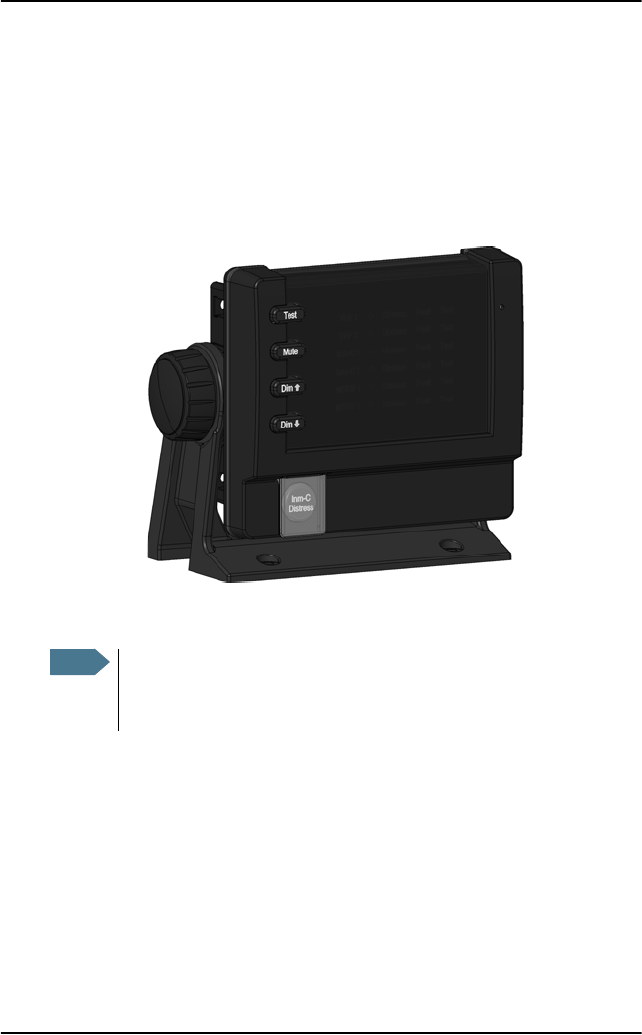
SAILOR 6101A Alarm Panel
The SAILOR 6101A Alarm Panel is dedicated to Inmarsat C. It has one distress
button for sending distress alerts over the Inmarsat C satellite network.
The display shows distress alert transmission in progress and distress alerts
received on the Inmarsat C network.
Through the Ethernet connector you can interface to two Inmarsat C systems.
Note
If a distress alert is initiated on a system with duplicated units, only
one of the units will send the alarm. The display shows a marker
next to the name of the selected unit.
Chapter 1: Introduction
The Alarm Panel 3
1111
Introduction
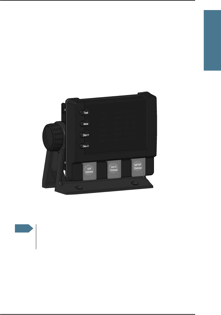
SAILOR 6103A Multi Alarm Panel
The SIALOR 6103A Multi Alarm Panel connects to VHF equipment, MF/HF
equipment and Inmarsat C equipment, and has a distress button for each type
of system.
The display shows distress messages received. It also indicates equipment
type (VHF, MF/HF or Inmarsat C) when the equipment is detected by the Multi
Alarm Panel.
Through the Ethernet connector you can interface to two Inmarsat C systems,
two VHF systems and two MF/HF systems.
Note
If a distress alert is initiated on a system with duplicated units, only
one of the units will send the alarm. The display shows a marker
next to the name of the selected unit.

Chapter 1: Introduction
4The AlarmPanel

Chapter 2: Using the Alarm Panel
6 Starting up the Alarm Panel
Starting up the Alarm Panel
To start up the Alarm Panel, do as follows:
1. Switch on the Alarm Panel.
Use the remote on/off switch, if installed. otherwise, the Alarm Panel is
automatically powered with the system.
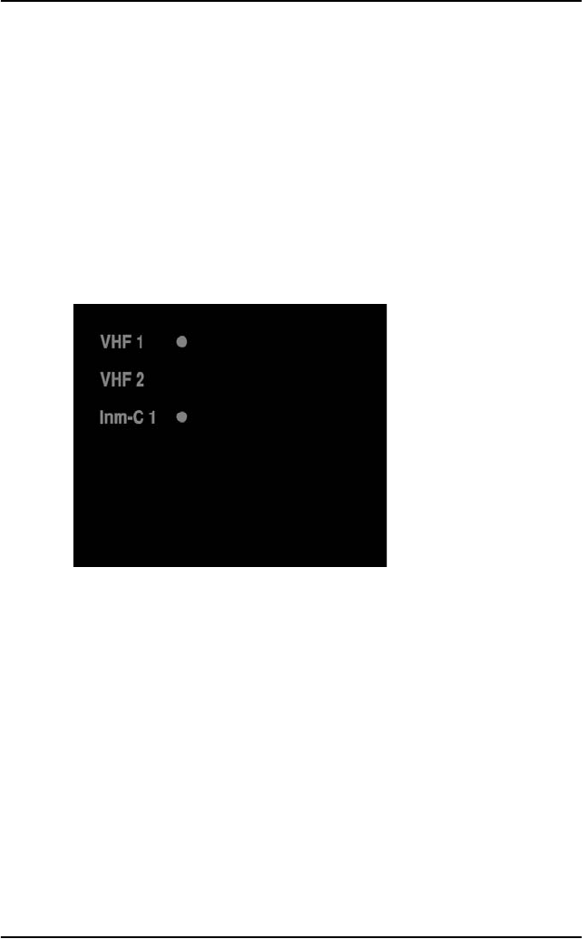
2. The first column of the display shows which systems are connected to the
Alarm Panel. A marker next to a system shows that it is the primary system
for sending distress alerts or distress calls.
In the example above, two VHF radios and one Inmarsat C system are
connected to the Alarm Panel. VHF 1 and Inm-C 1 can be used for sending a
distress call/alert.
• On the SAILOR 6101A you can connect two Inmarsat C systems.
• On the SAILOR 6103A you can connect two VHF systems, two Inmarsat C
systems and two MF/HF systems.
Chapter 2: Using the Alarm Panel
Sending a Distress alert 7
2222
Using the Alarm Panel
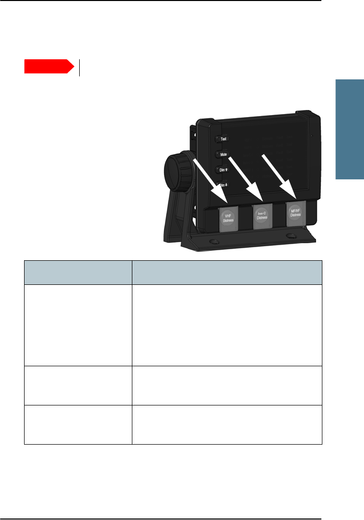
Sending a Distress alert
To send a Distress alert, do as follows:
1. Open the cover for the Distress
button you want to use (VHF,
Inm C or MF/HF).
2. Press and hold the button until
the light is steady and the
buzzer stops (approximately 5
seconds).
For further details, see the user manual for the system you are using (VHF,
Mini-C GMDSS or MF/HF).
Important
Never send a Distress alert if you are not in distress!
Behavior Meaning
Button light flashes,
buzzer sounds.
Marker in the display
flashes with the button
light.
The Distress button is pressed. Hold until light
and sound changes (approximately 5 seconds).
Button light constant,
buzzer is silent
The Distress alert is being sent
(normally within 10 to 30 seconds)
Button light shortly off
every 15 seconds
In Inmarsat C systems: The Distress alert is
confirmed
Chapter 2: Using the Alarm Panel
8 Receiving Distress or Urgency messages
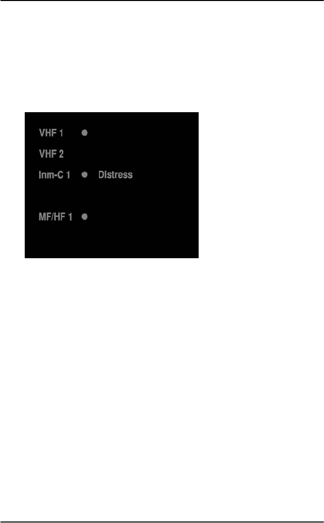
Receiving Distress or Urgency messages
When a Distress or Urgency message is received, the display of the
Alarm Panel shows a flashing Distress text and the buzzer sounds periodically.
The Distress text is shown next to the system on which the message was
received.
Check the connected system to see the contents of the message. In the
example above check the Message Terminal in your Inmarsat C system to see
the message.
Chapter 2: Using the Alarm Panel
Displaying faults 9
2222
Using the Alarm Panel
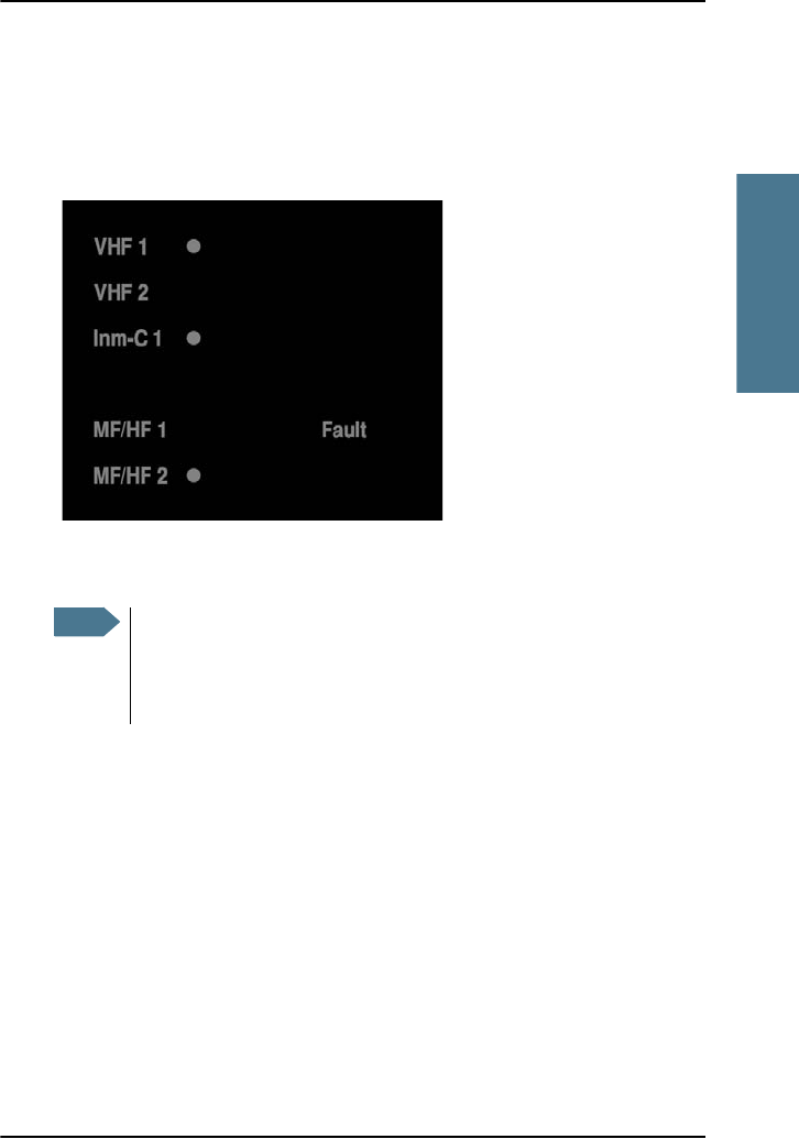
Displaying faults
The display of the Alarm Panel can show faults in the connected VHF,
Inmarsat C or MF/HF equipment.
Check the connected equipment for the cause of the fault. In the example
above, you should check MF/HF radio number 1.
Note
If the defective system is configured to be the primary system for
sending distress, the other system of the same type (if any) is
automatically selected in stead. In the example above, MF/HF 2 is
automatically selected because MF/HF 1 is defective.
Chapter 2: Using the Alarm Panel
10 General functions
General functions
Buttons in front panel
Apart from the Distress button(s) described in Sending a Distress alert on
page 7, the front panel has four other buttons: Test, Mute, and
.
Testing the Alarm Panel
To test the light and sound indicators in the Alarm Panel, do as follows:
1. Press and hold the Test button.
Verify that all light indicators and alarm buttons are flashing.
2. While holding the Test button, press any other button, including the
Distress button.
The buzzer sounds to indicate that the pressed button and the buzzer is
working.
Muting the alarm sound
To mute the alarm sound while it is on, press the Mute button.
Note
This test only verifies the function of the Alarm Panel itself, not of
any connected equipment or the total system. For information on
how to test the system, refer to the manual for the individual system
(Inmarsat C, VHF or MF/HF).
Note
Alarm sounds are muted on all connected units until they are
activated by a new event.

Chapter 2: Using the Alarm Panel
General functions 11
2222
Using the Alarm Panel
Adjusting the light
To increase the light intensity, press and hold the button.
To decrease the light intensity, press and hold the button.
Note
The light always goes to full intensity if there is an event such as a
Distress message, a fault or the Test button is pressed.
You can always use the Dim buttons to dim the light again if you
want to.

Chapter 2: Using the Alarm Panel
12 General functions

13
Chapter 1
1111
Installing the Alarm Panel
Installing the Alarm Panel 1
This chapter provides a description of how to unpack, store and install the
Alarm Panel. It contains the following sections:
•Initial inspection
•Storage
•To install the Alarm Panel
For information on cable connections, see Connecting cables on page 21.

Chapter 1: Installing the Alarm Panel
14 Initial inspection
Initial inspection
Inspect the shipping carton immediately upon receipt for evidence of
mishandling during transport. If the shipping carton is severely damaged or
water stained, request that the carrier's agent be present when opening the
carton. Save the carton packing material for future use.
Check that the contents of the shipment are according to the enclosed packing
list. If the contents are incomplete, if there is mechanical damage or defect, or
if the Alarm Panel does not work properly, notify your dealer.
After unpacking the Alarm Panel, inspect it thoroughly for damage and loose
components or fittings.
Storage
The Alarm Panel may be stored or shipped in temperatures between -40° C
and +80° C. Protect the Alarm Panel from extreme temperature variation
which can cause condensation.
We recommend that you unpack the Alarm Panel immediately on delivery.
Warning! To avoid electrical shock, do not apply power to the
Alarm Panel if there is any sign of shipping damage to any
part of the front or rear panel or the outer cover. Read the
safety summary at the front of this manual before
installing or operating the Alarm Panel.

Chapter 1: Installing the Alarm Panel
To install the Alarm Panel 15
1111
Installing the Alarm Panel
To install the Alarm Panel
General installation requirements
Normally the Alarm Panel is installed at the conning position on the bridge.
You can mount the Alarm Panel as a flush-mounted unit integrated in a
console, on a desktop or in an overhead position.
Make sure the Compass Safe Distance is maintained. See General
specifications on page 31.
Mounting the Alarm Panel
The next pages describe how to mount the Alarm Panel on a desktop, in an
overhead position and flush mounted in a console.
Note
The mounting procedure is the same for the Alarm Panel and the
Multi Alarm Panel so the descriptions in this chapter cover both
types of Alarm Panel.
Chapter 1: Installing the Alarm Panel
To install the Alarm Panel 17
1111
Installing the Alarm Panel
Overhead mounting
You can mount the Alarm Panel in an overhead position using the mounting
bracket. For details on how to mount the Alarm Panel, see Mounting the
Alarm Panel with the mounting bracket on page 18.
Chapter 1: Installing the Alarm Panel
18 To install the Alarm Panel
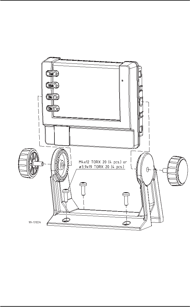
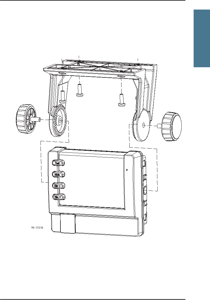
Mounting the Alarm Panel with the mounting bracket
To mount the Alarm Panel
using the mounting bracket, do
as follows:
1. Find a suitable location to
mount the Alarm Panel.
Make sure there is
minimum 80 mm of free
space for cable access
behind the Alarm Panel.
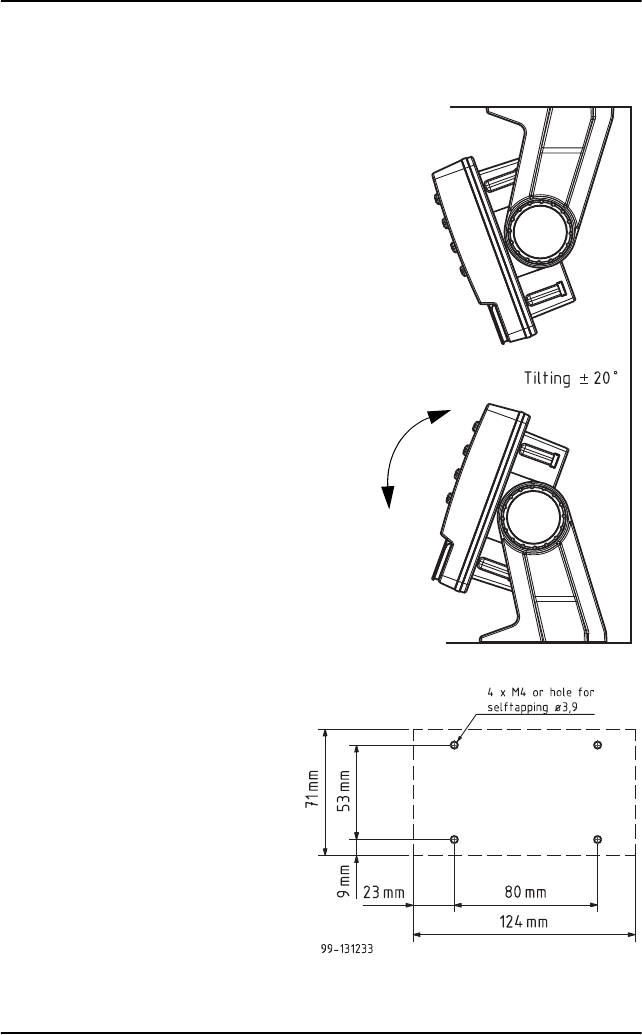
2. Use the four holes to fasten
the mounting bracket to the
mounting surface. Screws
are included with the
mounting bracket.
3. Place the Alarm Panel in the
mounting bracket.
4. Mount the two knobs on the
sides of the bracket, but do
not tighten them yet.
5. Connect the cables as
described in Connecting
cables on page 21.
6. Adjust the angle of the
Alarm Panel to the wanted
position. The bracket can be
adjusted ± 20°.
7. Tighten the two knobs on
the sides of the bracket
when the Alarm Panel is in
the correct position.
Chapter 1: Installing the Alarm Panel
To install the Alarm Panel 19
1111
Installing the Alarm Panel
Flush mount
You can mount the Alarm Panel in a flat surface, e.g. in a console, using the
Flush mount bracket and screws included with the Alarm Panel.
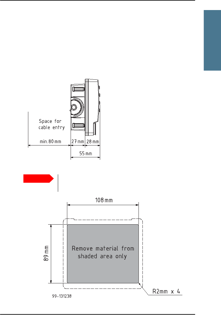
To mount the Alarm Panel in a console, do as follows:
1. Find a suitable location in the console. Check that there is enough space
for the Alarm Panel and an additional 80 mm space for cable entry.
2. Cut a hole of 89 mm x 108 mm for the Alarm Panel.
Important
The scale in the below drawing is not 1:1! Do not use it as a
template without checking the dimensions.
Chapter 1: Installing the Alarm Panel
20 To install the Alarm Panel
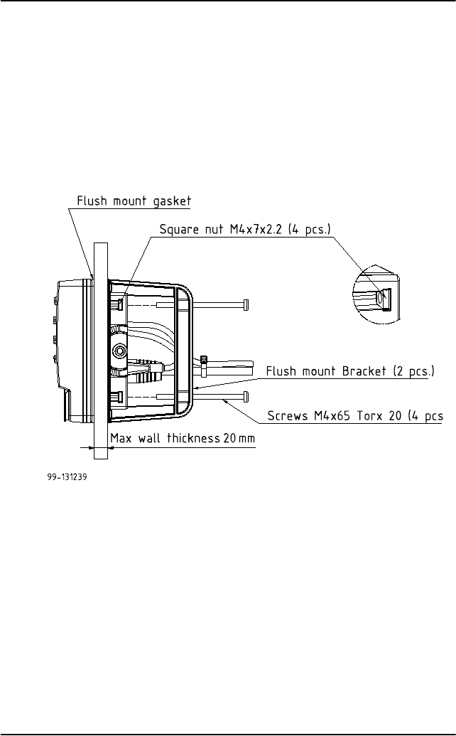
3. Place the 4 square nuts in the cut-outs on the sides of the Alarm Panel, two
on each side.
4. Ensure that the flush mount gasket is placed correctly on the Alarm Panel.
5. Fit the Alarm Panel into the cut-out in the console.
6. Mount the flush mount bracket on the back of the Alarm Panel by mounting
the 4 Torx screws through the bracket and into the square nuts placed in
the Alarm Panel.
7. Fasten the 4 Torx scre ws .
8. Connect the cables as described in Connecting cables on page 21.

Chapter 2: Connecting cables
22 Connectors
Connectors
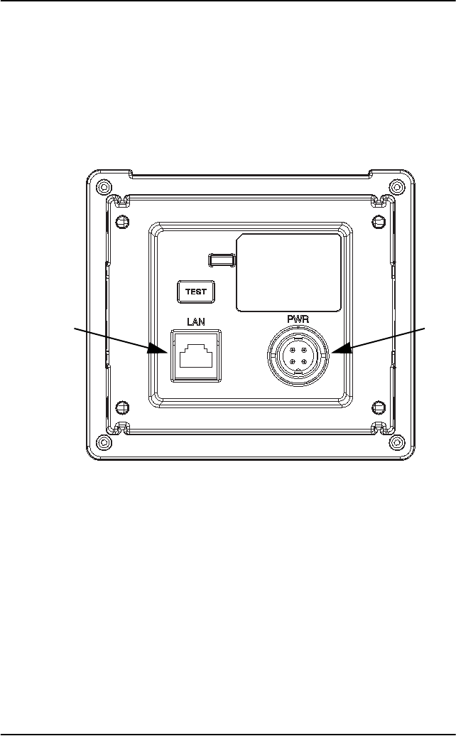
Overview
The drawing below shows the connectors on the Alarm Panel.
Power
Ethernet
Chapter 2: Connecting cables
Connectors 23
2222
Connecting cables
LAN interface
Overview
There is one Ethernet (10/100 MB) connector on the rear panel of the
Alarm Panel, used for communicating with connected equipment, such as a
Message Terminal, VHF and MF/HF equipment.
The interface supports PoE (Power over Ethernet), which means the
Alarm Panel can be powered from a PoE device through the Ethernet.
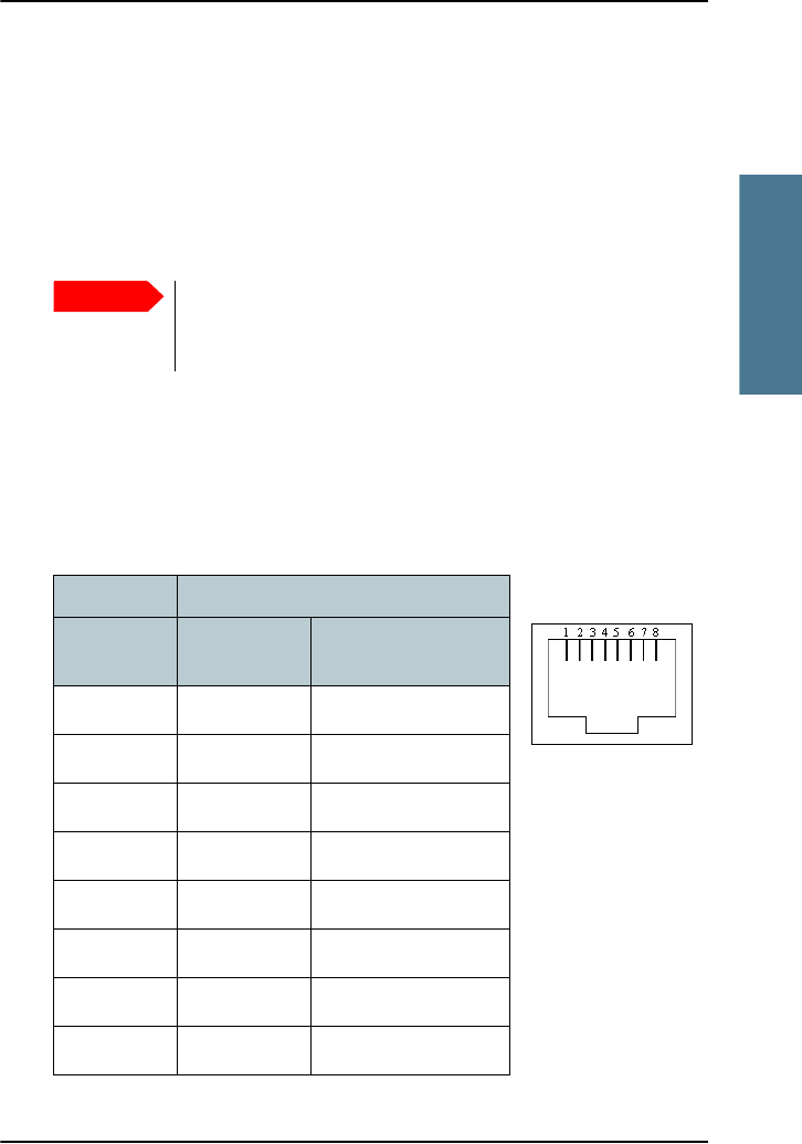
Pin-out
The figure and table below show the connector outline and pin assignments.
Important
Only connect to units that are part of the system. For safety and
compliance reasons, the Ethernet interface is restricted to
internal communication in an isolated system.
Pin function
Pin number 10/100
DC on spares
10/100 mixed DC &
data
1Rx+ Rx+DC+ (PoE)
2Rx- Rx-DC+ (PoE)
3Tx+ Tx+DC- (PoE)
4 DC+ (PoE) unused
5 DC+ (PoE) unused
6Tx-Tx-DC- (PoE)
7 DC- (PoE) unused
8 DC- (PoE) unused
RJ-45 female
Chapter 2: Connecting cables
24 Connectors
DC Power input
Overview
The DC Power input connects to a DC supply with 24 V DC nominal (10.8 to
32 V DC). The interface also has a “remote on/off” function.
The Power connector is a custom connector; a matching cable with connector
is included in the delivery.
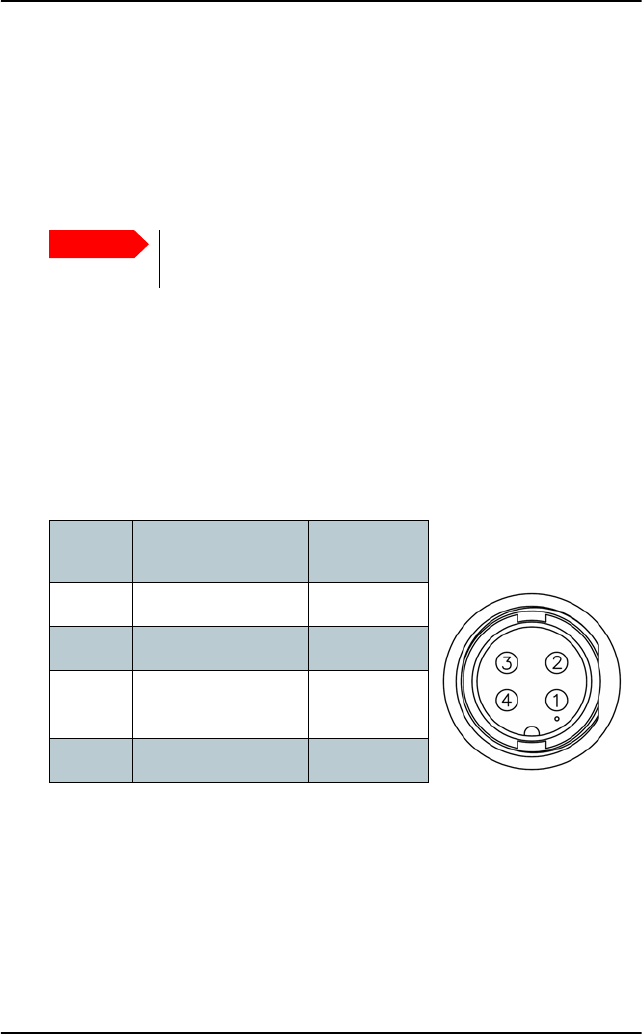
Pin-out
The figure and table below show the connector outline on the Alarm Panel,
pin assignments and wire color in the power cable delivered with the
Alarm Panel.
Remote on/off (ON_IN)
With the Remote on/off function you can switch the Alarm Panel on and off
from a remote location, using a switch. Note that the Alarm Panel does not
have a power button, so it is always on, unless you use the remote on/off
function.
Important
If you are not going to use the remote on/off function, you must
connect pin 3 (ON_IN) to pin 2 (DC-) permanently.
Pin
number Pin function Wire color in
power cable
1 DC+ (10.8 - 32 V DC) Red
2DC- (0 V DC) Black
3ON_IN
(see below)
White
4Not connected Blue
Front view on Alarm Panel
Panel lock, 4 pin male

Chapter 2: Connecting cables
Connectors 25
2222
Connecting cables
To use the Remote on/off function in the Alarm Panel, do as follows:
1. Connect a switch to the white wire in the power cable (pin 3, ON_IN, in the
Power connector.)
2. Connect the other side of the switch to the black wire in the power cable
(DC- (0 V DC) in the Power connector), so that pin 3 in the Power connector
is connected to DC- (with a resistance less than 10 k when the switch is
closed.
• Switch closed: Alarm Panel is on
• Switch open: Alarm Panel is off

Chapter 2: Connecting cables
26 Cable requirements
Cable requirements
Before using the Alarm Panel for the first time, check that all cables are
correctly wired and fastened.
Grounding
All cables attached to the Alarm Panel must be shielded.
• The shield of the Ethernet cable must be connected to ship ground in the
Ethernet switch.
• The shield of the power cable must be connected to ship ground at the
power supply.
Cable requirements
The power cable supplied with your system is 2.5 m long with AWG 16 wires
and a custom connector at one end. If you are going to use another cable or
extend the supplied cable, make sure the cables are dimensioned correctly.
When the cable is connected to the power supply, there must be minimum
10.8 V at the end of the cable.
The Ethernet cable must be Cat. 5E or higher. Max. length is 100 m.
Chapter 2: Connecting cables
Connecting the Alarm Panel 27
2222
Connecting cables
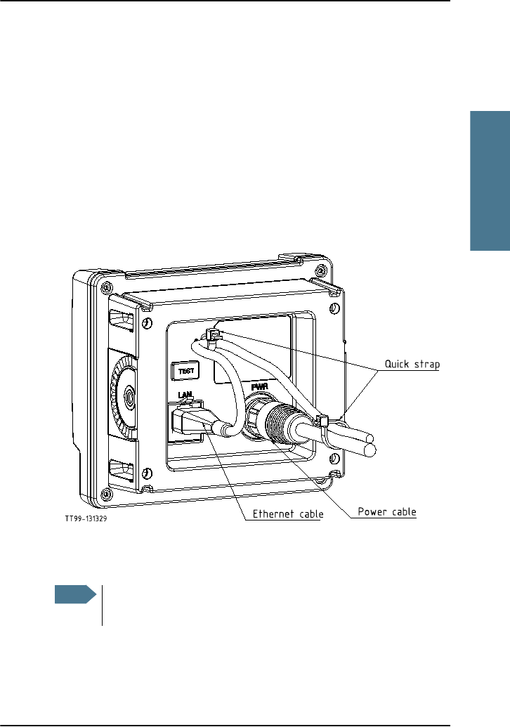
Connecting the Alarm Panel
This section covers both versions of the Alarm Panel, SAILOR 6101A and
SAILOR 6103A.
To connect the Alarm Panel, do as follows:
1. Connect the power cable according to the description in DC Power input on
page 24.
2. Connect an Ethernet cable to the LAN connector on the Alarm Panel.
3. Attach the cables with cable straps as shown below.
4. Connect the other end of the Ethernet cable to an Ethernet switch or
alternatively a PoE switch.
Note
If you are using PoE as your power source for the Alarm Panel,
the DC cable is optional.

Chapter 2: Connecting cables
28 Connecting multiple Alarm Panels
5. Connect the Ethernet interfaces on your Message Terminal, VHF radio
and/or your MF/HF radio to the same switch, or a switch in the same
network.
When connected and powered, all the units are automatically set up to
communicate with each other in the Ethernet network.
Connecting multiple Alarm Panels
You can connect up to twelve Alarm Panels on the same subnet (e.g. six
SAILOR 6101A and six SAILOR 6103A).
To connect multiple Alarm Panels, do as follows:
1. Connect the Alarm Panels to an Ethernet switch.
2. Connect the Ethernet switch to the system(s) used for transmitting the
alarms, e.g. the Message Terminal in a Mini-C system or a VHF radio.
The units are automatically set up to communicate with each other in the
Ethernet network.
Important
Only connect units that are part of the system. For safety
and compliance reasons, the Ethernet interface is
restricted to internal communication in an isolated system.

29
Chapter 3
3333
Service and repair
Service and repair 3
This chapter describes what to do with defective units, including how to pack
them for shipment if they are to be returned.
Introduction
The Alarm Panel designed to operate without preventive routine maintenance.
Although the Alarm Panel is designed and built very service friendly, we
strongly recommend that any acting service technician is trained specifically
on the product. Repair or repair attempts performed by unqualified personnel
may limit the warranty. The warranty on the system is defined and outlined by
the distributor that supplied the system.
We do not recommend repairing the Alarm Panel on board the ship. Replace
the defective unit and have it repaired at a qualified workshop on shore.
For further information on warranty and service, you may also use the Thrane
& Thrane home page at http://www.thrane.com.

Chapter 3: Service and repair
30 Repacking for shipment
Repacking for shipment
The shipping carton has been carefully designed to protect the Alarm Panel
and its accessories during shipment. This carton and its associated packing
material should be used when repacking for shipment. Attach a tag indicating
the type of service required, return address, model number and full serial
number. Mark the carton FRAGILE to ensure careful handling.
If the original shipping carton is not available, the following general
instructions should be used for repacking with commercially available
material.
1. Wrap the Alarm Panel in heavy paper or plastic. Attach a tag indicating the
type of service required, return address, model number and full serial
number.
2. Use a strong shipping container, e.g. a double walled carton of 160 kg test
material.
3. Protect the front- and rear panel with cardboard and insert a 7 cm to 10 cm
layer of shock-absorbing material between all surfaces of the equipment
and the sides of the container.
4. Seal the shipping container securely.
5. Mark the shipping container FRAGILE to ensure careful handling.

31
Appendix A
AAAA
Specifications
Specifications A
General specifications
Item Specifications
Mounting
method
Flush mount or bracket
Power 10.8 to 32 V DC, with “remote on/off” input
Power
Consumption
Typical 1 W, Maximum 3 W
Interfaces Ethernet (10/100 Mbit), RJ45 connector
DC input, custom panel lock connector
Compliance • IEC 60945
• Wheelmark approved.
IP protection IP30
Ambient
Temperature
-15°C to 55°C
Storage
temperature
-40°C to 80°C
Relative
humidity
+40°C 93% 1 cycle

Appendix A: Specifications
32 General specifications
Vibration Vibration Sweep:
2 Hz - 13,2 Hz at ± 1 mm
13,2 Hz - 100 Hz at 7m/s2
2 h dwell at each resonance, otherwise 2 h at 30Hz in all three
axes
Compass safe
distance
1m
Dimensions
H x W x D
Without bracket: 107 mm x 121 mm x 55 mm
With bracket: 124 mm x 153 mm x 90 mm
Weight Without bracket: 302 g
Item Specifications

33
Glossary
BBBB
Glossary
Glossary B
A
AWG American Wire Gauge. A means of specifying wire diameters.
D
DC Direct Current
G
GMDSS Global Maritime Distress Safety System. The system is intended to
perform the following functions: alerting (including position
determination of the unit in distress), search and rescue
coordination, locating (homing), maritime safety information
broadcasts, general communications, and bridge-to-bridge
communications.
H
HF High Frequency. Radio frequencies between 3 and 30 MHz. Used
for direct, long-distance (often inter-continental)
communications.
I
IMSO International Maritime Satellite Organisation. An
intergovernmental body established to ensure that Inmarsat
continues to meet its public service obligations.
Inmarsat C A service provided by Inmarsat, offering two-way, store-and-
forward packet data communications via a small, low-cost
terminal. Handles operational and personal messages, including
e-mail, telex and fax, as well as distress and safety
communications.

Glossary
34
IP Ingress Protection. An international classification system for the
sealing effectiveness of enclosures of electrical equipment against
the intrusion into the equipment of foreign bodies (i.e. tools, dust,
fingers) and moisture. This classification system uses the letters
"IP" followed by two or three digits. An "x" is used for one of the
digits if there is only one class of protection; e.g. IPX4 which
addresses moisture resistance only.
M
MF Medium Frequency. Radio frequencies (RF) in the range of 300
kHz to 3 MHz. Navtex, which is part of the current Global Maritime
Distress Safety System occupies 518 kHz and 490 kHz for important
digital text broadcasts.
P
PoE Power over Ethernet. A standard for combining power supply with
transmission of data over the Ethernet. The source unit "injects"
power into the Ethernet cable and the power is "picked up" at the
connected device.
R
Rx Receive
T
Tx Transmit
V
VHF Very High Frequency. The radio frequency range from 30 MHz to
300 MHz. Ideal for short-distance terrestrial communication.

35
Index
CCCC
Index
Index C
A
Alarm Panel
description, 2
Multi, 3
types of, 1
C
cable requirements, 26
connectors
DC power input, 24
LAN, 23
overview, 22
D
DC power input connector, 24
desktop mounting, 16
dim function, 11
dimensions, 32
distress
sending alert, 7
distress message indication, 8
document number
this manual, i
E
Ethernet connector, 23
F
faults
indication in display, 9
flush mount, 19
I
indication
faults in connected equipment, 9
incoming messages, 8
initial inspection, 14
Inmarsat C Alarm Panel, 2
installation, 15
L
LAN connector, 23
light
adjusting, 11
M
manual
document number, i
message received indication, 8
mounting
flush mount, 19
on desktop, 16
Multi Alarm Panel description, 3
muting alarm sound, 10
P
power input connector, 24
R
receiving distress or urgency messages,
8
repacking for shipment, 30
repair, 29
