Thrane and Thrane A S 6300 SAILOR 6311 MF/HF 150W DSC CLass A FCC User Manual RadioTelex UM
Thrane & Thrane A/S SAILOR 6311 MF/HF 150W DSC CLass A FCC RadioTelex UM
Contents
manual radio telex
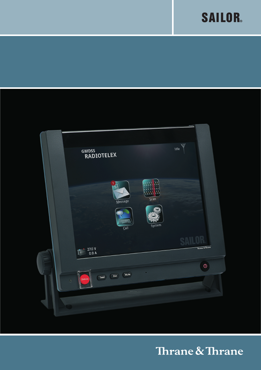
SAILOR 6300 MF/HF Radiotelex
USER MANUAL
SAILOR 6300 MF/HF Radiotelex
User manual
Document number: 98-132519-A
Release date: January 18, 2011
Disclaimer
Any responsibility or liability for loss or damage in connection with the use of this
product and the accompanying documentation is disclaimed by Thrane & Thrane. The
information in this manual is provided for information purposes only, is subject to
change without notice and may contain errors or inaccuracies.
Manuals issued by Thrane & Thrane are periodically revised and updated. Anyone
relying on this information should acquire the most current version e.g. from
http://www.thrane.com or from the distributor.
Thrane & Thrane is not responsible for the content or accuracy of any translations or
reproductions, in whole or in part, of this manual from any other source.
Copyright
© 2011 Thrane & Thrane A/S. All rights reserved.
GPL notification
The software included in this product contains copyrighted software that is licensed
under the GPL/LGPL. The verbatim licenses can be found online at:
http://www.gnu.org/licenses/old-licenses/gpl-2.0.html
http://www.gnu.org/licenses/old-licenses/lgpl-2.1.html
You may obtain the complete corresponding source code from us for a period of three
years after our last shipment of this product, which will be no earlier than December 31,
2015, by sending a money order or check for DKK 50 to:
SW Technology/GPL Compliance,
Thrane & Thrane A/S,
Lundtoftegaardsvej 93D
2800 Lyngby
DENMARK
Please write "source for product SAILOR 6300 MF/HF Radiotelex" in the memo line of
your payment.
You may also find a copy of the source at http://www.thrane.com/foss.
This offer is valid to anyone in receipt of this information.
Warranties
Any attempt to install or execute software not supplied by Thrane & Thrane on this
device will result in the warranty being void. Any attempt to modify the software on this
device in a way not specified by Thrane & Thrane will result in the warranty being void.
Trademark Acknowledgements
•Thrane & Thrane is a registered trademark of Thrane & Thrane A/S in the European
Union and the United States.
•SAILOR is a registered trademark of Thrane & Thrane A/S in the European Union, the
United States and other countries.
• Other product and company names mentioned in this manual may be trademarks or
trade names of their respective owners.

iv
Safety summary 1
The following general safety precautions must be observed during all
phases of operation, service and repair of this equipment. Failure to comply
with these precautions or with specific warnings elsewhere in this manual
violates safety standards of design, manufacture and intended use of the
equipment. Thrane & Thrane assumes no liability for the customer's failure
to comply with these requirements.
GROUND THE EQUIPMENT
To minimise shock hazard, the equipment chassis and cabinet must be
connected to an electrical ground and the cable instructions must be
followed.
DO NOT OPERATE IN AN EXPLOSIVE ATMOSPHERE
Do not operate the equipment in the presence of flammable gases or fumes.
Operation of any electrical equipment in such an environment constitutes a
definite safety hazard.
KEEP AWAY FROM LIVE CIRCUITS
Operating personnel must not remove equipment covers. Component
replacement and internal adjustment must be made by qualified
maintenance personnel.
DO NOT SUBSTITUTE PARTS OR MODIFY EQUIPMENT
Because of the danger of introducing additional hazards, do not substitute
parts or perform any unauthorized modification to the equipment.
COMPASS SAFE DISTANCE
Minimum compass safe distance: 1.3 m from the Message Terminal.
Failure to comply with the rules above will void the warranty!
v
About the manual 2
Manual overview
This manual describes how to use the SAILOR 6300 MF/HF
Radiotelex. Note that this manual does not cover installation of the
system. For information on installation refer to the installation
manuals [2] and [3] listed below.
This manual has the following chapters:
•Introduction contains an overview of the Radiotelex system.
•Using the system explains how to send Distress alerts and how
to use the Radiotelex application for sending and receiving
telex messages.
•Troubleshooting contains a short troubleshooting guide and
explains how to check the status of the system.
Related documents
The below list shows the documents related to this manual and to
the Radiotelex system.
Ref Title and description Document
number
[1] SAILOR 6300 MF/HF DSC,
User manual
98-131070
[2] SAILOR 6300 MF/HF DSC,
Installation manual
98-130890
[3] SAILOR 6006 and SAILOR 6007
Message Terminal, Installation manual
98-130088
[4] SAILOR 6081 PSU and Charger,
Installation and user manual
98-130980

vi
Typography
In this manual, typography is used as indicated below:
Bold is used for the following purposes:
• To emphasize words or sentences.
Example: “Do not push the Distress button if you are not in
distress”.
• To indicate what the user should select in the user interface.
Example: “Select Message > Inbox”.
Italic is used to emphasize the paragraph title in cross-references.
Example: “For further information, see System overview on
page 2”.

vii
Contents
Chapter 1 Introduction
System overview .................................................................2
The Radiotelex application .................................................3
Chapter 2 Using the system
Before you start ..................................................................6
Sending a DSC Distress alert ..............................................7
Sending a Distress telex .....................................................8
Cancelling a Distress alert ..................................................9
Overview of the Radiotelex user interface ......................... 10
Setting up a telex call ........................................................13
Making a telex call ............................................................16
Messages .........................................................................23
Receiving telex messages .................................................26
Scanning frequencies ....................................................... 27
System settings ................................................................33
Power status ....................................................................34
Chapter 3 Troubleshooting
Getting support ................................................................37
Generating a diagnostic report .........................................38
Troubleshooting guide .....................................................39
Status signaling ................................................................41

1
Chapter 1
1111
Introduction
Introduction 1
With the SAILOR 6300 MF/HF Radiotelex system you can send and receive
telex messages and send DSC Distress alerts over MF/HF radio. The Radiotelex
program runs on a SAILOR 6006 Message Terminal with a keyboard.
The Message Terminal is connected to a SAILOR 6300 MF/HF radio, which
transmits and receives the telex messages and transmits DSC Distress alerts.
The units are further described in the installation manuals for the MF/HF radio
[2] and the Message Terminal [3].
This chapter has the following sections:
•System overview
•The Radiotelex application
Chapter 1: Introduction
2 System overview
System overview
The SAILOR 6300 MF/HF Radiotelex communicates on MF or HF radio
frequencies. It is approved for shipboard installations to operate within the
Global Maritime Distress and Safety System (GMDSS).
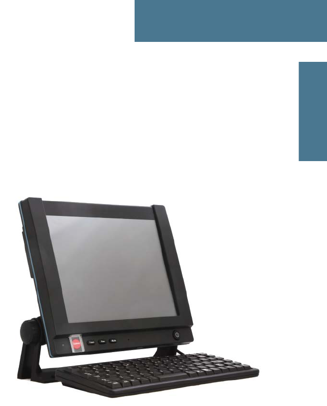
Radiotelex supports worldwide ship-to-ship, ship-to-shore, and shore-to-ship
communication. A coast station can act as a relay between the Radiotelex
system and an end receiver without any telex capabilities. The Radiotelex
system supports both 4- and 5-digit selective calls and 9-digit MMSI (Maritime
Mobile Service Identity) numbers.
Radiotelex is well suited for transmission over very long distances. It has
global coverage, even including the North pole and the South pole.
Fax
subscriber
Ship station Ship station
Radiotelex
Coast station
Radiotelex
Chapter 1: Introduction
The Radiotelex application 3
1111
Introduction
The Radiotelex application
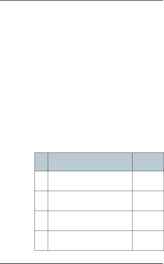
The Radiotelex application runs on the SAILOR 6006 Message Terminal. On
the Message Terminal you can read and write telex messages and set up telex
calls.
The Message Terminal has a touch-screen and a keyboard for operating the
Radiotelex system.
f
The Radiotelex application starts up automatically when the Message
Terminal is powered. Note that the Message Terminal must always be
powered in a GMDSS system.
For details on how to operate the system, see Using the system on page 5.

Chapter 1: Introduction
4 The Radiotelex application

5
Chapter 2
2222
Using the system
Using the system 2
This chapter describes how to operate the SAILOR 6300 MF/HF Radiotelex. It
has the following sections:
•Before you start
•Sending a DSC Distress alert
•Sending a Distress telex
•Cancelling a Distress alert
•Overview of the Radiotelex user interface
•Setting up a telex call
•Making a telex call
•Messages
•Receiving telex messages
•Scanning frequencies
•System settings
•Power status

Chapter 2: Using the system
6 Before you start
Before you start
The SAILOR 6300 MF/HF Radiotelex system must be set up for telex. This
involves the following steps:
At the time of installation
1. SAILOR 6006 is configurable to be either a mini-C GMDSS terminal or a
Radiotelex terminal. At the first power-up you must set up the Message
Terminal to be a Radiotelex terminal.
2. At first power up you must also configure the answer back string and the ID
for your system. For further information, see the installation manual for the
SAILOR 6300 MF/HF DSC [2].
3. The MF/HF radio must be enabled to use telex. This is done by entering a
PIN code in the MF/HF transceiver. For further information, see the
installation manual for the SAILOR 6300 MF/HF DSC [2].
Before use
1. The Message Terminal must be on.
2. The MF/HF radio must be in telex mode: On the MF/HF radio, push the
Mode button repeatedly until the display shows TLX.
For details, see the user manual for the SAILOR 6300 MF/HF DSC [1].
Chapter 2: Using the system
Sending a DSC Distress alert 7
2222
Using the system
Sending a DSC Distress alert
The Distress button procedure below is the same on the Message Terminal as
on the SAILOR 6300 MF/HF DSC.
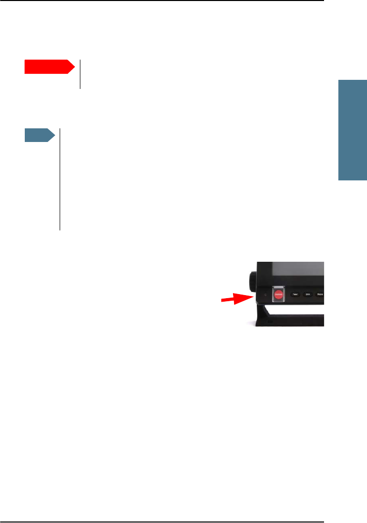
To send a Distress alert, do as follows:
1. Open the cover for the Distress button.
2. Push and hold the button for more than 3
seconds to transmit an undesignated DSC
Distress alert. While the button is pushed, the
Message Terminal shows a popup with a
countdown and the attached control unit(s)
beep.
To cancel a Distress alert, see Cancelling a Distress alert on page 9.
Important
Only send a Distress alert if you are in immediate danger!
The Distress alert can be compared to a MAYDAY call.
Note
If the subsequent communication is to be telex, use the ALERT
function in the MF/HF radio to set up telex subsequent
communication before pushing the button. Refer to the SAILOR 6300
MF/HF DSC User manual for details on how to set up the MF/HF
radio. When the DSC Distress alert is sent, a popup appears on the
Message Terminal guiding you to the Call page, which is
automatically set up to Broadcast FEC using the telex frequency
matching the Distress alert.

Chapter 2: Using the system
8 Sending a Distress telex
Sending a Distress telex
If telex subsequent communication is selected for the DSC Distress alert, a
popup appears and guides you to the Call page, which is automatically set up
to Broadcast FEC on the Distress frequency assigned by the MF/HF radio. You
can now send a Distress telex as follows:
1. In the Call setup page, select Call at the bottom of the page.
2. Type in further information about the distress. Press Enter or select Send
after each line. Include:
• Distress alert sent at xx:xx (time of the Distress alert)
• Own MMSI and name of the ship
• Own position
• Information about your distress
3. When the message is complete, select Break to end the message.
For further information on how to send a telex, see Setting up a telex call on
page 13 and Making a telex call on page 16.

Chapter 2: Using the system
Cancelling a Distress alert 9
2222
Using the system
Cancelling a Distress alert
To cancel a Distress alert with telex subsequent communication, do as follows:
1. On the MF/HF radio, cancel the Distress alert by selecting the softkey
ANNUL. For details, see the user manual for the SAILOR 6300 MF/HF DSC.
2. The radio sends a Distress cancel (on 1-6 channels).
3. The radio enters telex subsequent communication on the first telex distress
frequency.
4. The Message Terminal shows that the system is engaged in DSC
subsequent communication.
5. Select Call from the main menu.
6. In the Call page of the Message Terminal, select Call to send a Broadcast
FEC message cancelling the Distress alert. In the message, include as a
minimum:
• This is a Distress cancel for Distress alert sent at xx:xx (time of the
Distress alert)
• Own MMSI and name of the ship
• Own position
• The reason for cancelling the Distress alert
7. When the message is complete, select Break to end the message
8. On the MF/HF radio, press OK if more frequencies are involved, or QUIT to
end the distress session if the whole procedure is completed.
9. If more frequencies are involved, the radio automatically switches to the
next frequency. Repeat step 4 to step 8 for every frequency.
For further information on how to send a telex, see Setting up a telex call on
page 13 and Making a telex call on page 16.
Chapter 2: Using the system
10 Overview of the Radiotelex user interface
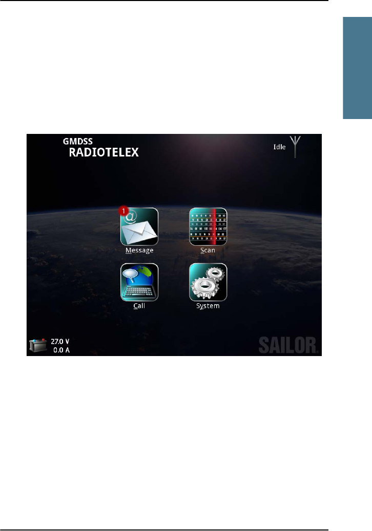
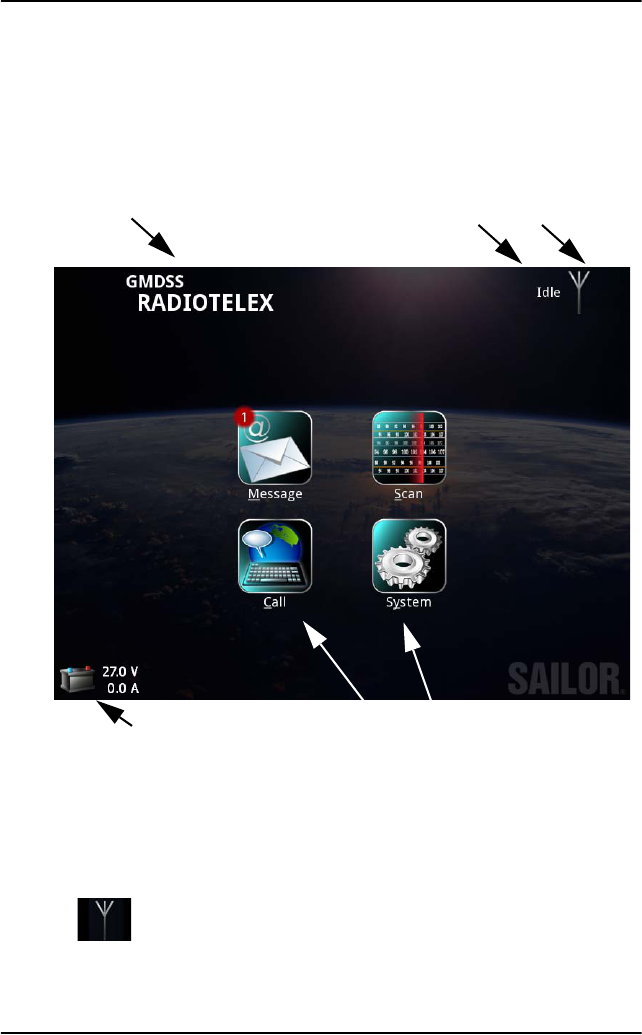
Overview of the Radiotelex user interface
When the system is powered, the Message Terminal display shows the main
menu and a status field. Below is an overview of the main screen in the
SAILOR 6300 MF/HF Radiotelex.
•Name of current page: When you have entered a subpage, this field shows
the name of the page.
•Status field: This field shows a short status message next to the
Status/warning icon.
•Status/Warning icon: This icon can show:
System is idle.
Main menu items
Name of current page
Power status
Status field Status/warning icon
Chapter 2: Using the system
Overview of the Radiotelex user interface 11
2222
Using the system
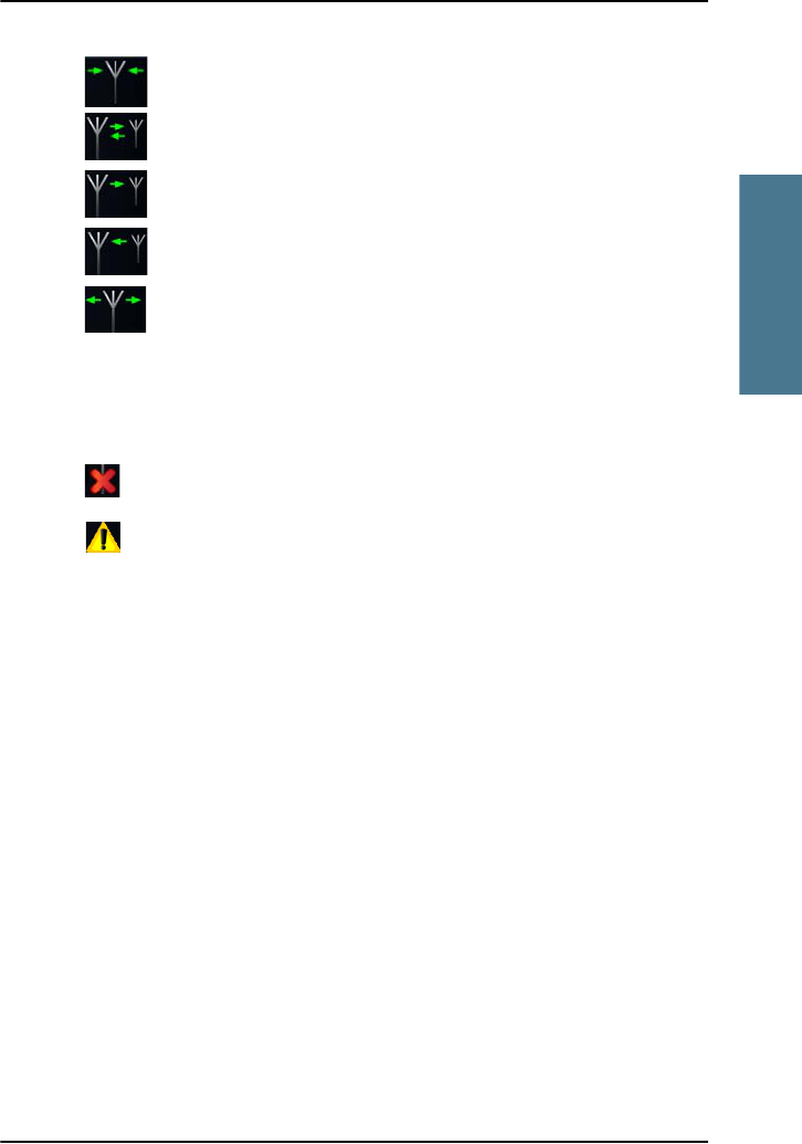
System is scanning the frequencies selected in the scan list.
ARQ connection.
Outgoing selective FEC.
Incoming FEC (selective or broadcast).
Outgoing Broadcast FEC.
Red arrows instead of green arrows in the above icons mean that the
signal quality is poor.
Together with each of these symbols one of the following icons may also
appear:
Error.
Warning.
For details of warnings/errors, see Information of events on page 41.
•Power status: Shows the status of the backup battery.
•Main menu items: Select these items to access the subpages.

Chapter 2: Using the system
12 Overview of the Radiotelex user interface
Navigating the Radiotelex
To navigate and select items, you can do one of the following:
Touch screen: Select items by touching them with your finger on the screen.
Keyboard:
• When an item has an underlined letter, you may type Alt + <letter> to
select the item, e.g. type Alt+S to select the Scan menu.
•Press Esc to go back one level in the menu system or to close the current
window.
•Use the tab and arrow keys to navigate through items.
•Press Space to select items.
•Press F1 to see the list of active errors and warnings.
Trackball (if fitted):
• Use the trackball in the corner of the keyboard to move the cursor around
on the screen.
• Use the two buttons in the left corner the same way you use the left and
right buttons on a mouse.

Chapter 2: Using the system
Setting up a telex call 13
2222
Using the system
Setting up a telex call
Setting up the transmission mode
The Radiotelex system has three transmission modes:
•ARQ (Automatic Repetition reQuest): A mode where two stations can
communicate without breaking the connection. The direction is changed
with an “over” command.
•Selective FEC (Forward Error Correction): A one-way mode to one station.
•Broadcast FEC: A one-way mode broadcast to all stations. E.g. used in
distress situations or for news or coast station traffic lists.
Note
The system must be configured and enabled before use. See Before
you start on page 6.
Chapter 2: Using the system
14 Setting up a telex call
To set up the transmission mode, do as follows:
1. From the main menu, select Call.
2. Select ARQ, Selective FEC or Broadcast FEC.
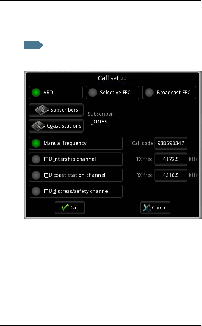
Selecting the frequency for the call
You can select the frequency for your call in one of the following ways:
•Manual frequency: Allows you to type in the frequency in the Tx freq and Rx
freq fields (Rx is only relevant for ARQ calls).
When you select a coast station from the Coast stations list, the primary
frequencies are listed, and you can select the frequency to use.
Note
If Telex is not selected in the MF/HF radio you get a warning that
the radio is occupied. Use the Mode button on the radio to switch
to Telex.

Chapter 2: Using the system
Setting up a telex call 15
2222
Using the system
•ITU intership channel: Allows you to type in a channel number to use for
ship-to-ship communication.
•ITU coast station channel: Allows you to type in a channel number to use
for communication with a coast station.
•ITU distress/safety channel: Allows you to type in a channel number to use
for distress or safety communication. If the entered channel is not a distress
or safety channel, the display shows a warning.
There are 6 dedicated distress frequencies for simplex FEC telex distress:
2174.5 kHz (Channel 1), 4177.5 kHz (Channel 411), 6268 kHz (Channel 611),
8376.5 kHz (Channel 801), 12520 kHz (Channel 1287) and 16695 kHz
(Channel 1624).
When selecting a channel number the corresponding frequency is
automatically displayed.
Selecting the recipient for the call
Broadcast FECs are broadcast to all stations listening on the selected
frequency, so you cannot specify recipients for broadcast calls.
For ARQ or Selective FEC you must specify the recipient for your telex.
• If the recipient is in the Subscribers list or the Coast stations list, simply
select the recipient from the list.
• If the recipient is not in any of the lists, type in the recipient’s number in
the Call code field. You can use either a 9-digit MMSI number or a 4-digit
or 5-digit selective calling number.
Coast stations have either a 9-digit MMSI number starting with 00 or a 4-digit
selective call (SelCall) number.
Ship subscribers have either a 9-digit MMSI number or a 5-digit SelCall
number.
Chapter 2: Using the system
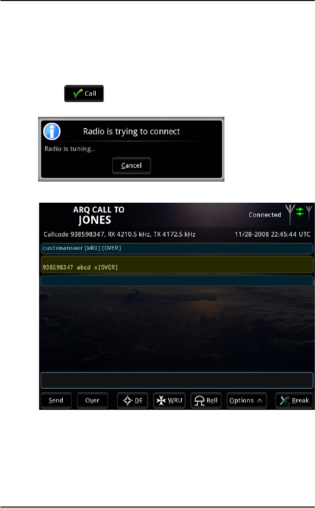
16 Making a telex call
Making a telex call
When you have set up telex mode, frequency/channel and recipient as
described in the previous section, you are ready to make a call. Do as follows:
1. Select at the bottom of the Call setup page to start your telex
session. The display shows that the radio is trying to connect.
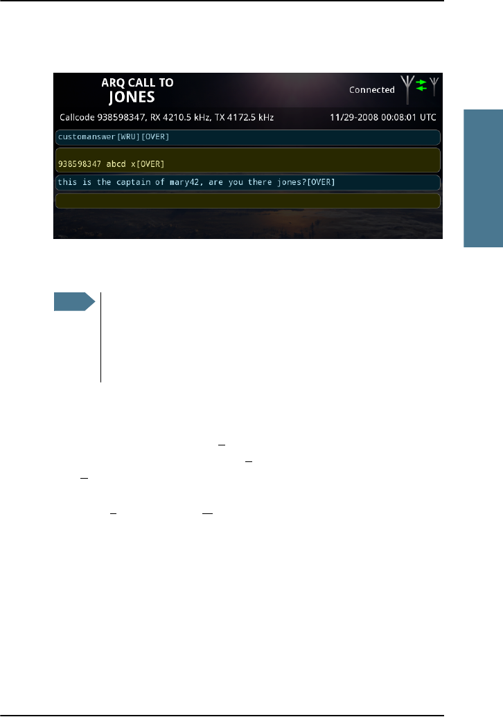
2. When the connection is established, the telex page opens.
If you have selected Automatic identification (DE/WRU), your answer back
string is automatically sent. For ARQ calls, the answer back string is
followed by a WRU command requesting the recipient’s answer back
string. When the recipient has answered and has sent an Over command,
you can start your message.
Chapter 2: Using the system
Making a telex call 17
2222
Using the system
For a description of all the items at the bottom of the page, see Options in
the telex page on page 20.
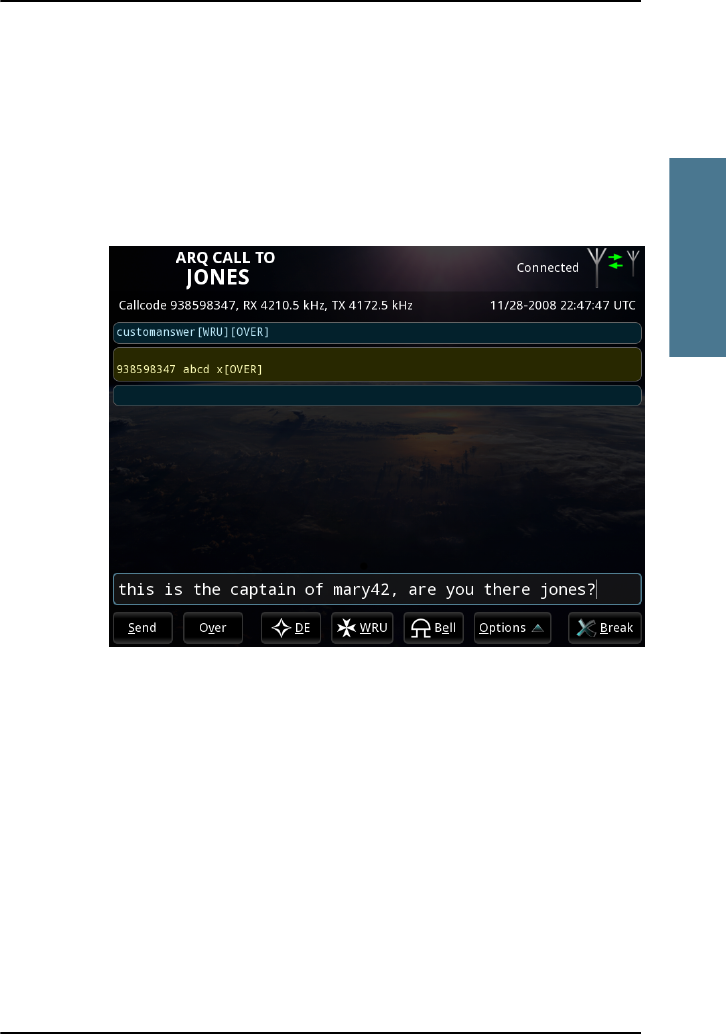
3. You can send text in the following two ways:
• Type in your message directly in the text line at the bottom, using your
connected keyboard or the on-screen keyboard, which is activated by
pressing the text line on the screen and then the keyboard icon that
appears in the right side of the text line.
Chapter 2: Using the system
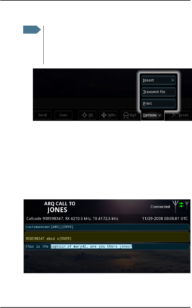
18 Making a telex call
• Select Options > Transmit file and select the file you want to transmit.
You can combine the two methods by adding text before or after the file
contents, and type text at the bottom while the file is being transmitted.
If you transmitted a file and you do not want to add further text, skip the
next step and go directly to step 5. For information on how to create a file
for later transmission, see Writing message files for telex on page 23.
4. When you have finished your message, press Enter or select Send at the
bottom of the page.
The text is now transmitted. You can follow the progress in the inverted
part of the message.
Note
The system begins to transmit immediately when the file is
selected. Pressing OVER while a file is being transferred does not
result in a change of direction until the entire file is transmitted.
To stop the transmission, select Cancel file transfer. Then you
can use the OVER command to change the direction.
Chapter 2: Using the system
Making a telex call 19
2222
Using the system
5. For ARQ only: when you want the recipient to write back, select Over at the
bottom of the page, or type [OVER] or +?.
The recipient can now type in a message for you. The message will appear
in the field just below your message.
6. When the recipient has placed the [OVER] command too, you can type
more text to continue the conversation.
7. To end the telex session, select Break. If you do not want to wait for
exchange of DE/WRU, you can select Break now! in the popup that appears
after Break is selected.
The call is then disconnected. You can see all telex sessions initiated by
you under Sent Items in the Message page. See Viewing Sent items on
page 25.
Note
If the remote station forces an OVER on your part while you are
transmitting data, 1-2 characters may incorrectly be marked has
having been sent while the remote station may not have received
these characters. We do not recommend forcing a change of
direction while the other station is sending data.
Chapter 2: Using the system
20 Making a telex call
Options in the telex page
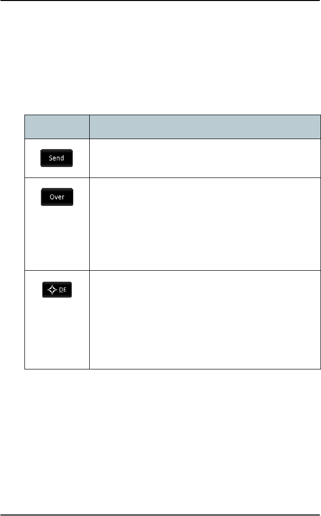
Buttons
The table below shows the functions of the buttons that can appear at the
bottom of the page:
Button Function
Transmits the text you have typed in the text line at the
bottom.
(ARQ only) Changes direction, so the recipient can write
back. You cannot send any text after an Over command,
until the direction is changed back to your side.
However, if you send more text while the OVER command
is waiting to be sent, the OVER is removed and replaced
by your new text.
Transmits your answer back string.
The answer back string is stored in the MF/HF radio
during installation, using the Identification page in the
Message Terminal (System > Settings > Identification).
In Call settings you can set up the system to automatically
send DE/WRU (System > Settings > Call settings).
Chapter 2: Using the system
Making a telex call 21
2222
Using the system
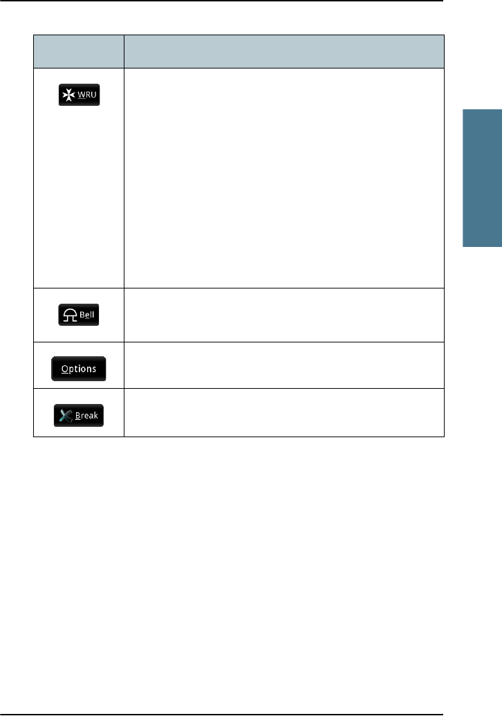
(ARQ only) Inserts a WRU command (Who are you? -
request for identification) in your text. This command is
automatically followed by [OVER], so that the recipient
can answer back.
When the WRU command is sent, you cannot send any
more text until the direction is changed back to your side.
However, if you send more text while the WRU command
is waiting to be sent, the WRU is removed and replaced by
your new text.
In the Call settings page you can set up the system to
automatically send DE/WRU.
Inserts a BELL command (can make e.g. a buzzer sound at
the recipient).
Opens the Options menu, described in the next section.
Stops the communication link.
Button Function
Chapter 2: Using the system
22 Making a telex call
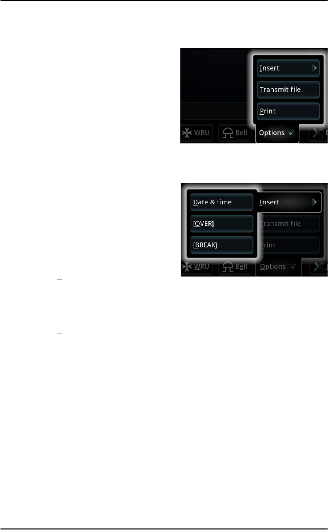
Options menu
To open the Options menu in the telex
page, select Options at the bottom of
the page.
You now have the following options:
•Insert
•Date & Time: Inserts the
current date and time (UTC
format) in your message. The
syntax of the Date and time is
the format selected under
Settings > Date and Time
format.
•[OVER]: Inserts an OVER
command in your text, so that when you select Send or press Enter,
your text is sent and the direction is changed to the recipient
immediately after.
•[BREAK]: Inserts a BREAK command in your text, so that when you
select Send or press Enter, your text is sent and the communication is
stopped immediately after.
•Transmit file
Allows you to select a text file to transmit. For information on how to write
and save the text file, see Writing message files for telex on page 23.
•Print
Sends the text in the telex page to the printer.
Chapter 2: Using the system
Messages 23
2222
Using the system
Messages
Writing message files for telex
If you want to write longer messages, you can use the Message function.
To write a message, do as follows:
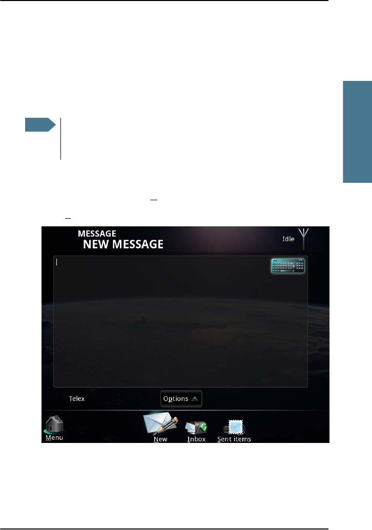
1. From the main menu, select Message.
2. Select New (if not already selected).
To make sure the text is properly formatted at the receiving end, we
recommend starting the file with a few empty lines (press Enter).
Note
You cannot send the message directly from the Message editor. To
send the message you have to save it to a file and then make a telex
call and load the file as described in Making a telex call on page 16.
Chapter 2: Using the system
24 Messages
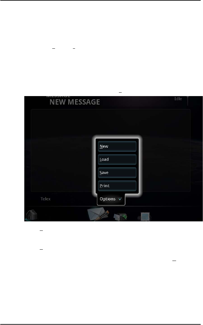
3. You now have two options:
• Type in the text using your keyboard or the on-screen keyboard in the
top right corner. Note that you can only use telex characters.
• Select Options > Load and select a file to load into the editor. You can
then edit the text before you save it. Note that you cannot load a file if it
contains characters that are not telex characters.
Supported characters are: a b c d e f g h i j k l m n o p q r s t u v w x y z 0 1
2 3 4 5 6 7 8 9 - ? : ( ) . , ' = / +
4. When the message is complete, select Options.
5. Select Save to save the message to a file. You can save it to the Message
Terminal or to a USB memory stick.
6. Select Print if you want to print the message on your connected printer.
7. If you want to clear the editor and start a new message, select New.
Chapter 2: Using the system
Messages 25
2222
Using the system
Viewing the Inbox
To see the Inbox, select Inbox at the bottom of the Message page.
The Inbox page shows all telex messages sent to you and initiated by another
station. It shows both single messages and ARQ conversations initiated by the
other part.
Viewing Sent items
To see the Sent items, select Sent items at the bottom of the Message page.
The Sent items page shows all telex communication initiated by you.
Printing, saving or deleting messages
Use the tools symbol to print, delete or save messages. You can use
the tools symbol from within a message or from the list of messages (Inbox or
Sent items).
From within a message
To delete, print or save a message from within the message, do as follows:
1. Select the message you want to delete, save or print.
2. Select in the top right corner of the display.
3. Select Delete, Print or save.
Note
The Inbox can hold 1000 messages. The oldest messages are deleted
when this limit is exceeded.
Note
Sent items can hold 1000 messages. The oldest messages are
deleted when this limit is exceeded.
Chapter 2: Using the system
26 Receiving telex messages
From the Inbox or Sent items
You can only print a message from within the message, as shown in the
previous section.
To delete or save messages from the Inbox or Sent items, do as follows:
1. Click in the lower left corner of the display.
2. Select the messages you want to delete or save.
You may use Select all to select all messages in the Inbox or Sent items, or
Clear all to clear all selections.
3. Select Delete to delete the selected messages or Save to save the selected
messages.
Receiving telex messages
The system can receive telex messages on all MF and HF telex frequencies,
including NAVTEX messages at 490 kHz, 518 kHz and 4209.5 kHz.
When a telex is received on your Message Terminal, the procedure is:
1. A popup appears and the telex page opens, showing the incoming
message.
2. If the call is an ARQ call, you can continue the communication as described
in Making a telex call on page 16.
All received telex messages, whether they are ARQ telexes initiated by the
other part or FEC telexes, are shown in the Inbox.
Note
You can only receive telexes on frequencies that you are scanning.
This means that the frequencies must be in the scan list, and a
scanning must be started. See the next section for details.
Exception for DSC subsequent communication: The radio will
automatically enable scanning on the correct frequency and only on
that frequency. When the DSC session is ended, the scan list of the
Message Terminal is used again.
Chapter 2: Using the system
Scanning frequencies 27
2222
Using the system
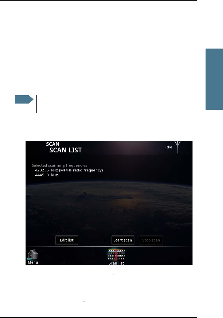
Scanning frequencies
When a scan is started, the system is ready to receive telex messages on the
selected scan frequencies. The MF/HF radio scans every listed channel for 3
seconds. If no traffic is detected, it continues to the next channel.
The scan list in the SAILOR 6300 MF/HF Radiotelex always shows the current
telex frequency of the connected MF/HF radio (indicated with “MF/HF radio
frequency”). In addition, you can add other telex frequencies that you want
the system to scan. See Editing the scan list on page 28.
To start a frequency scan, do as follows:
1. From the main menu, select Scan.
2. To scan the frequencies shown, select Start scan.
The Message Terminal informs the MF/HF radio to scan for the selected
frequencies. The status field in the top right corner shows Scanning.
3. To stop scanning, select Stop scan.
Note
If the system is in DSC subsequent communication mode, only the
frequency assigned by the MF/HF radio is scanned.
Chapter 2: Using the system
28 Scanning frequencies
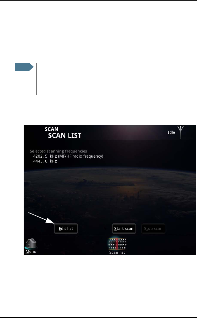
Editing the scan list
The MF/HF scanning frequency is automatically listed and can only be
changed from the MF/HF radio.
You can add, change or delete additional scanning frequencies in the list.
To edit the scan list, do as follows:
1. At the bottom of the SCAN LIST page, select the Edit list button.
Note
Scanning on multiple frequencies is primarily intended for receiving
ARQ calls. If many scan channels are specified you may not be able
to receive all incoming FEC calls, because FEC uses a much shorter
phasing sequence compared to ARQ.
Chapter 2: Using the system
Scanning frequencies 29
2222
Using the system
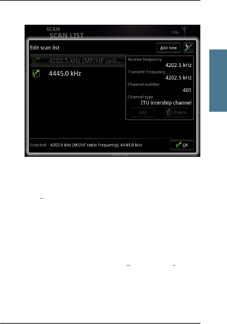
The list opens.
The green check marks show which frequencies are to be scanned.
2. To enable scanning of a frequency in the list, select the box next to the
frequency.
3. Select OK.
To change or delete a frequency in the list
1. Open the scan list as shown above.
2. Select the frequency (not the box).
The selected frequency is shown in the right side of the page.
3. To delete the frequency from the list, select Delete. Then select Yes.
Chapter 2: Using the system
30 Scanning frequencies
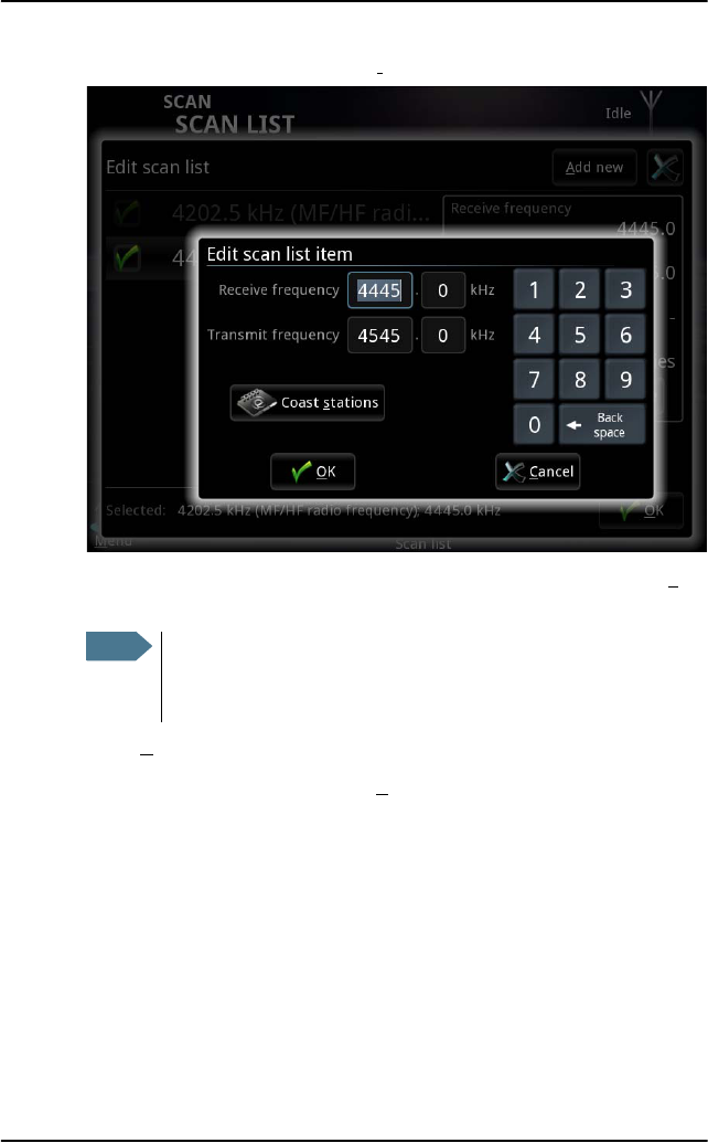
4. To change the frequency, select Edit.
5. Type in the Receive and Transmit frequencies or select from the list of Coast
stations.
6. Select OK.
7. To stop editing the scan list, select OK again.
Note
You must always type in both frequencies, even if you are only
going to use the receive frequency. The transmit frequency is
used to respond to incoming ARQ calls.
Chapter 2: Using the system
Scanning frequencies 31
2222
Using the system
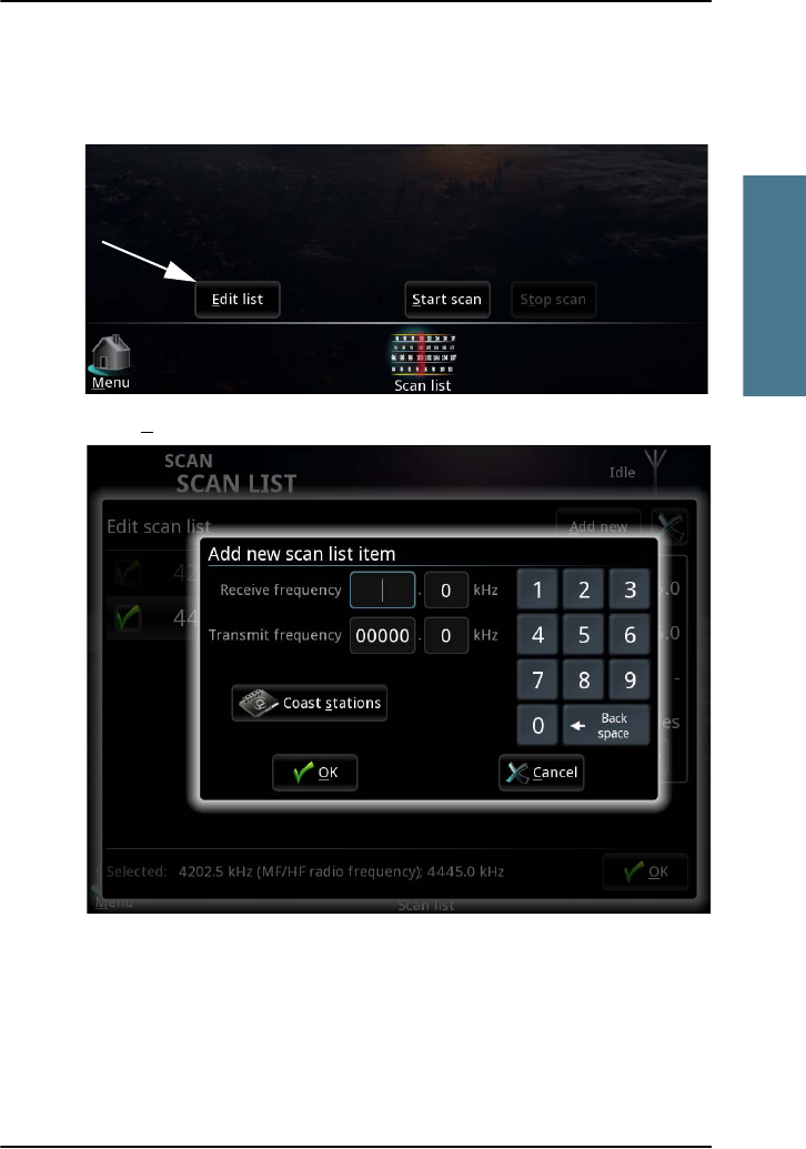
To add a frequency to the list
1. In the SCAN LIST page, select Edit list.
2. Select Add new in the top right corner.

Chapter 2: Using the system
32 Scanning frequencies
3. Type in the Receive and Transmit frequencies or select from the list of Coast
stations.
4. Select OK.
5. To stop editing the scan list, select OK again.
Note
You must always enter a transmit frequency, even if it is not used
(e.g. for NAVTEX, which is receive only). The transmit frequency
must be within a valid maritime frequency band specified by ITU.
The receive frequency must be between 490 and 27500 kHz.
Chapter 2: Using the system
System settings 33
2222
Using the system
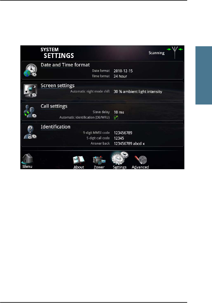
System settings
To access the system settings, select System > Settings.
In the System settings page you can set up:
• Date and time format. Set up how date and time is displayed.
• Screen settings. Set the ambient light level for switching to night mode.
• Call settings. Automatic DE/WRU and slave delay (the slave delay of 10 ms
is adequate for almost all scenarios).
• Identification. Configure call code and answer back string (DE). These
settings require password and are normally set up during installation.
Chapter 2: Using the system
34 Power status
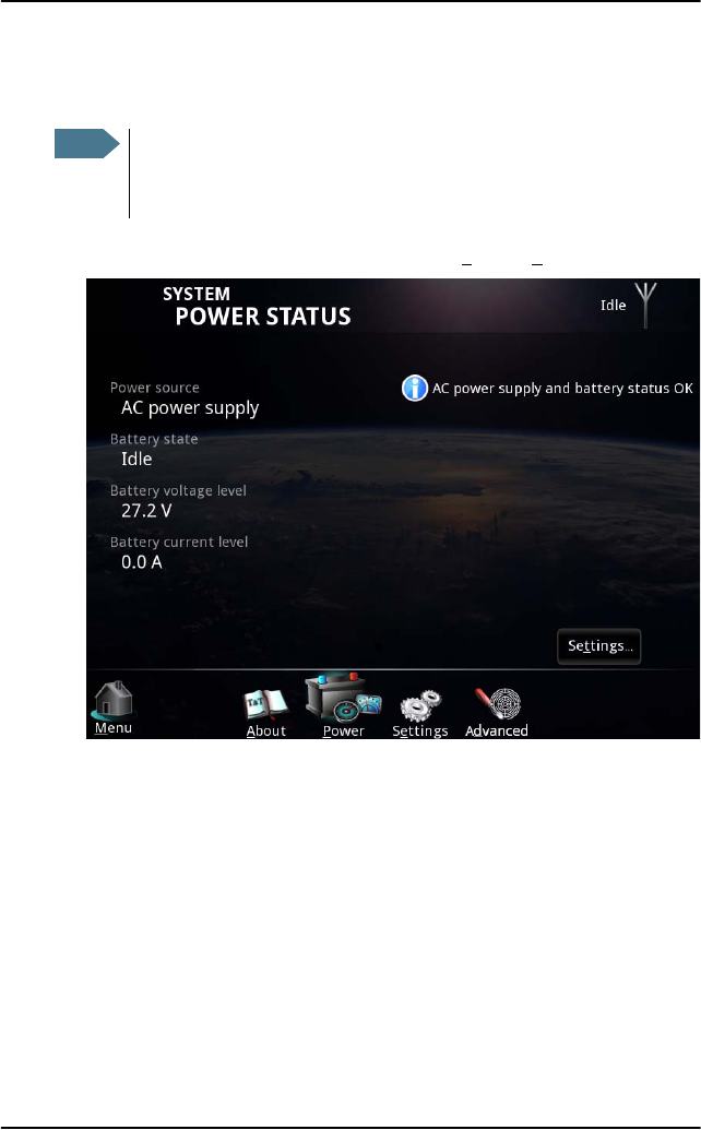
Power status
1. To see the status of the power source, select System > Power.
Note
The Power status only shows information for the SAILOR 6081 PSU
and charger. If you have a different power supply in your system,
there is no information available.
Chapter 2: Using the system
Power status 35
2222
Using the system
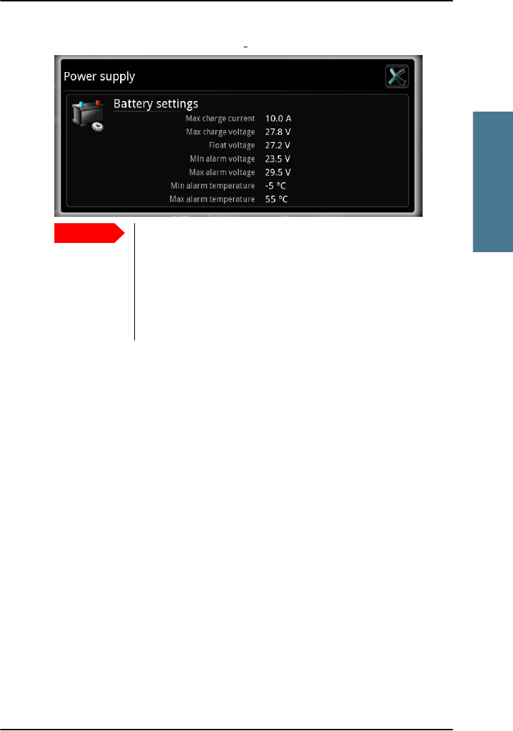
2. To see the power settings, select Settings... in the lower right corner.
Important
The default settings are suitable for most installations. Do
not change these settings unless you have a special battery
type or installation that requires different settings. Only
skilled personnel should change the power settings.
For information on how to change the settings, refer to the
installation manual for the MF/HF radio [2].

Chapter 2: Using the system
36 Power status

37
Chapter 3
3333
Troubleshooting
Troubleshooting 3
This chapter gives guidelines for troubleshooting and provides an overview of
the different means of status signaling. It has the following sections:
•Getting support
•Generating a diagnostic report
•Troubleshooting guide
•Status signaling
Getting support
If this manual does not provide the remedies to solve your problem, you may
want to contact your local distributor.
A list of certified partners and distributors is available on Thrane & Thrane’s
web site: www.thrane.com. Select Maritime and select Where to buy from the
top menu bar.
Chapter 3: Troubleshooting
38 Generating a diagnostic report
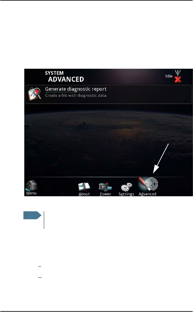
Generating a diagnostic report
To generate a diagnostic report, do as follows:
1. Select System.
2. Select Advanced at the bottom of the page.
3. Connect a USB memory stick to your Message Terminal.
4. Select Generate diagnostic report.
5. Select USB and browse to the location where you want your diagnostics
file.
6. Select Save.
7. S ele ct OK.
Note
Do not save the file on the Message Terminal itself; the file
format is not supported. Use a USB memory stick instead.

Chapter 3: Troubleshooting
Troubleshooting guide 39
3333
Troubleshooting
Troubleshooting guide
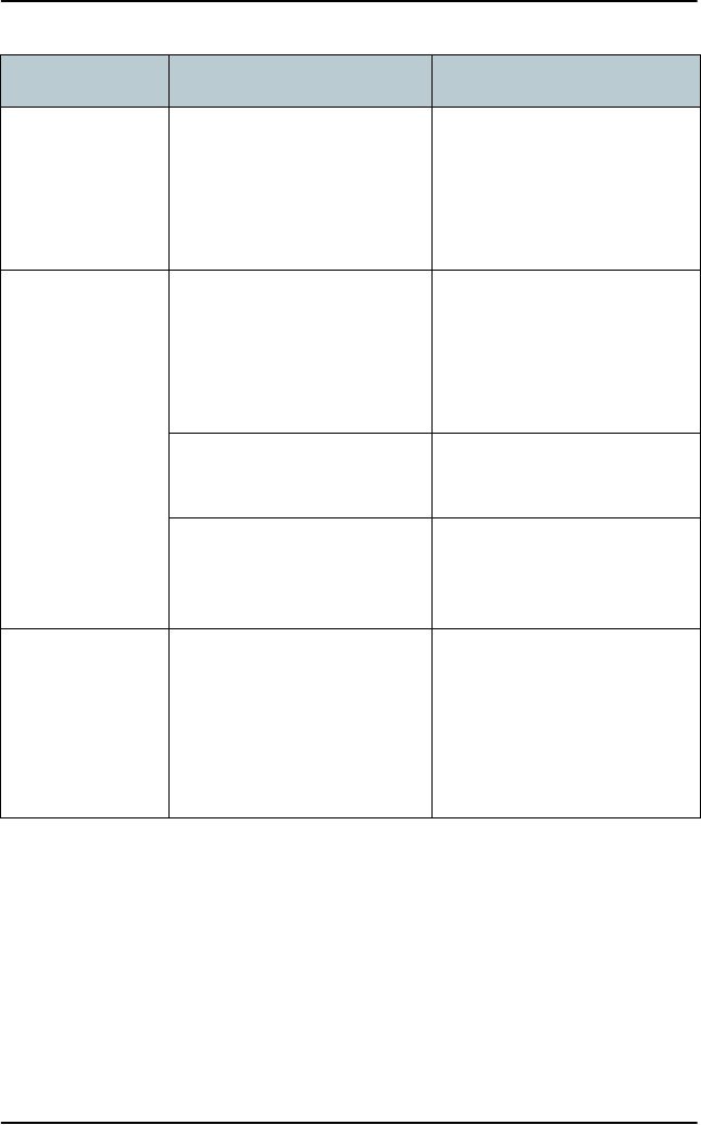
The below table provides information on some of the problems that might
occur, including possible causes and remedies to solve the problems.
Problem Possible cause Remedy
The system
cannot be
switched on
The Message Terminal has a
remote on/off switch, so the
power button is disabled.
If the Message Terminal is
using a remote on/off switch,
use that instead of the power
button.
There is no power on the
input to the Message
Terminal.
Check that all power cables
between the ship power
source and the Message
Terminal are connected
correctly, and that the power
source is on.
No battery
information in
the Message
Terminal
The Ethernet connection
from the power supply is not
working.
Check the Link activity
indicator at the connection
points in the Ethernet switch.
Check that the Ethernet
cables are connected
correctly and are not
damaged.
The power supply is not a
SAILOR 6081
None. Battery and power
information is only shown if
the power supply is a SAILOR
6081.
Chapter 3: Troubleshooting
40 Troubleshooting guide
No connection
between
Message
Terminal and
printer
The USB cable is damaged
or is not connected properly.
Check that the USB cable is
connected correctly and is
not damaged.
No connection
between
Message
Terminal and
MF/HF radio
The CAN connection does
not work.
Check that the CAN cables
are connected correctly to
the Message Terminal and
the MF/HF radio, and that
they are not damaged.
The MF/HF radio is not
switched on
Check that the MF/HF radio is
switched on and ready.
Other Switch off the MF/HF radio
and the Message Terminal
and switch them back on.
The Message
Terminal shows
“out of paper”
although there is
paper in the
printer.
The paper is not placed
correctly in the printer.
Adjust the paper to the left
side of the printer.
Problem Possible cause Remedy

Chapter 3: Troubleshooting
Status signaling 41
3333
Troubleshooting
Status signaling
The Message Terminal can show basic status and error messages.
The upper right corner of the display shows the most important status
information.
Information of events
Popup windows
When an event requires your attention, a popup window appears. When you
have read the text, select OK or press Esc to close the window.
If the window indicates an error that requires your action, the warning or error
icon will stay in the top right corner of the display as long as the problem
persists.
If the system uses a SAILOR 6081 PSU and Charger, the Message Terminal also
shows errors or warnings related to the power supply. For information on the
SAILOR 6081, see the manual for the SAILOR 6081 [4].
List of active warnings and errors
The top right corner of the display shows a short text about the current status.
The icon in the corner can change depending on the situation. The following
icons may show:
Antenna icon: The antenna icon can look different depending on the
status. For details, see page 10 in Overview of the Radiotelex user
interface.
Error.
Warning.
Select the icon or press F1 to see the list of active warnings and errors.
From the list of active warnings and errors you can access the event log.

Chapter 3: Troubleshooting
42 Status signaling
Event log
From the list of active errors or warnings, you can select Event log to see a list
of previous events. The list holds up to 100 events, including
•Errors
•Warnings
• Cleared warnings and errors.

43
Glossary
AAAA
Glossary
Glossary A
A
ARQ Automatic Repetition reQuest. An error-control method for data
transmission that uses acknowledgements and timeouts to
achieve reliable data transmission over an unreliable service. If
the sender does not receive an acknowledgment before the
timeout, it usually re-transmits the frame/packet until the sender
receives an acknowledgment or exceeds a predefined number of
re-transmissions.
C
CAN Controller-Area Network. A message based protocol designed to
allow microcontrollers and devices to communicate with each
other within a vehicle without a host computer.
D
DE A command used in a telex message to insert an answer-back
string identifying the sender of the message. The string should
normally contain the call sign.
DSC Digital Selective Calling. Primarily intended to initiate ship-to-
ship, ship-to-shore and shore-to-ship radiotelephone and MF/HF
radiotelex calls. Each DSC-equipped ship, shore station and group
is assigned a unique 9-digit Maritime Mobile Service Identity. DSC
distress alerts, which consist of a preformatted distress message,
are used to initiate emergency communication with ships and
rescue coordination centers.
F
FEC Forward Error Correction. A system of error control for data
transmission, whereby the sender adds redundant data to its
messages, also known as an error-correcting code. This allows

Glossary
44
the receiver to detect and correct errors without the need to ask
the sender for additional data. The advantage of forward error
correction is that a back-channel is not required.
G
GMDSS Global Maritime Distress Safety System. The system is intended to
perform the following functions: alerting (including position
determination of the unit in distress), search and rescue
coordination, locating (homing), maritime safety information
broadcasts, general communication, and bridge-to-bridge
communication.
GPL General Public License
H
HF High Frequency. The frequency band between 3 and 30 MHz.
Used for medium and long range terrestrial radio communication.
I
ITU International Telecommunication Union
L
LGPL Lesser General Public License
M
MF Medium Frequency. Radio frequencies (RF) in the range of 300
kHz to 3 MHz. Navtex, which is part of the current Global Maritime
Distress Safety System occupies 518 kHz and 490 kHz for important
digital text broadcasts.

Glossary
45
AAAA
Glossary
MMSI Maritime Mobile Service Identity. A series of nine digits which are
sent in digital form over a radio frequency channel in order to
uniquely identify ship stations, ship earth stations, coast stations,
coast earth stations, and group calls. These identities are formed
in such a way that the identity or part thereof can be used by
telephone and telex subscribers connected to the general
telecommunications network to call ships automatically.
N
NAVTEX NAVigational TEleX. An international automated medium-
frequency direct-printing service for delivery of navigational and
meteorological warnings and forecasts, as well as urgent marine
safety information to ships.
P
PIN Personal Identification Number
T
TLX TeLeprinter eXchange - also called telex.
U
USB Universal Serial Bus. A specification to establish communication
between devices and a host controller (usually personal
computers). USB is intended to replace many varieties of serial
and parallel ports. USB can connect computer peripherals such as
mice, keyboards, digital cameras, printers, personal media
players, flash drives, and external hard drives.
UTC Universal Time, Coordinated. The International Atomic Time (TAI)
with leap seconds added at irregular intervals to compensate for
the Earth’s slowing rotation. Leap seconds are used to allow UTC
to closely track UT1, which is mean solar time at the Royal
Observatory, Greenwich.


47
Index
BBBB
Index
Index B
A
alarm
voltage level, 34
answer back string
define, 33
insert, 20
B
battery charge
max. voltage and current, 34
battery status, 34
Bell button, 21
Break button, 21
buttons on screen during call, 20
C
call
make a telex call, 16
select frequency, 14
select recipient, 15
set up, 13
call code
for own system, 33
charge battery
max. voltage and current, 34
coast station
MMSI, 15
D
date and time format, setting, 33
DE and WRU
automatically insert, 33
DE button, 20
delete a message, 25
diagnostic report, 38
Distress
cancel, 9
send alert, 7
telex subsequent communication, 8
document number, this manual, i
documents, related, v
E
error messages, 41
F
file, transmit, 22
float voltage, 34
frequency
scan, 27
select, 14
I
icons, 10
Identification, 33
identification request (WRU), 21
Inbox, 25
initial setup, 6
insert date and time, 22
M
manual
document number, i

Index
48
message
delete, 25
print, 25
receive, 26
save, 25
MMSI
coast station, 15
subscriber, 15
N
night mode, 33
O
options
menu during call, 22
Over button, 20
overview
system, 1
user interface, 10
P
power
alarm level, 34
status, 34
power source, 34
prepare the system for telex, 6
print
current page, 22
message, 25
R
radiotelex overview, 2
receive telex, 26
recipient of call, 15
related manuals, v
S
safety summary, iv
save a message, 25
scan frequencies, 27
Send button, 20
Sent items, 25
slave delay, 33
status, 10
subscriber
MMSI, 15
system overview, 1
system settings, 33
T
telex
enable in radio, 6
make a call, 16
receive, 26
select frequency, 14
select recipient, 15
set up a call, 13
subsequent communication for
Distress, 8
time and date format, setting, 33
transmit a file, 22
troubleshooting, 39
typography used in this manual, vi
U
user interface, 3
navigate, 12
overview, 10


98-132519-A
Thrane & Thrane A/S • info@thrane.com • www.thrane.com