Thrane and Thrane A S TU5160 Sailor System 5000 150W GMDSS MF/HF SSB DSC NBDP User Manual 98 125065 THR B pmd
Thrane & Thrane A/S Sailor System 5000 150W GMDSS MF/HF SSB DSC NBDP 98 125065 THR B pmd
Contents
user manual 1
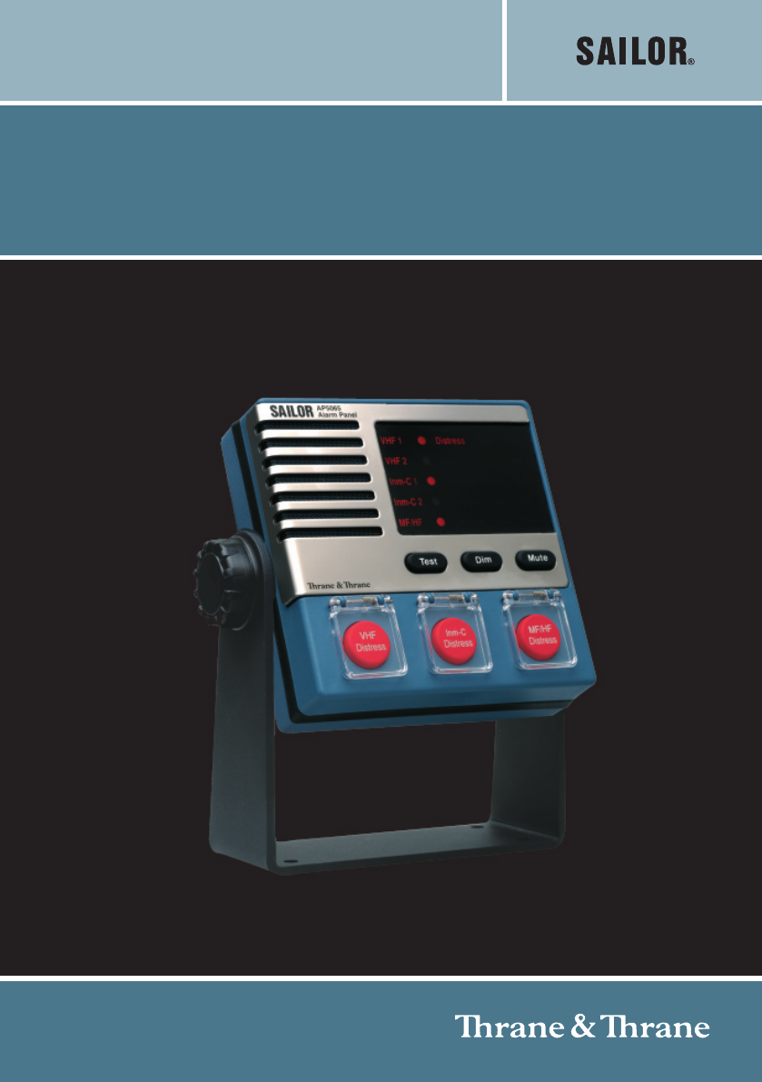
SAILOR AP5065 Alarm Panel
INSTALLATION MANUAL

1
0715
Disclaimer
Any responsibility or liability for loss or damage in connection with the use of this product and
the accompanying documentation is disclaimed by Thrane & Thrane. The information in this
manual is provided for information purposes only, is subject to change without notice, may
contain errors or inaccuracies, and represents no commitment whatsoever by Thrane &
Thrane. This agreement is governed by the laws of Denmark.
Manuals issued by Thrane & Thrane are periodically revised and updated. Anyone relying on
this information should satisfy himself/herself as to the most current version. Providers with
access to Thrane & Thrane’s Extranet may obtain current copies of manuals at: http://
extranet.thrane.com.
Thrane & Thrane is not responsible for the content or accuracy of any translations or
reproductions, in whole or in part, of this manual from any other source.
Contents
Introduction .............................................................................................................................. 3
General Description ............................................................................................................. 3
Technical Data ..................................................................................................................... 4
Operation................................................................................................................................... 5
Distress ................................................................................................................................5
General................................................................................................................................. 6
Installation................................................................................................................................. 7
Connector overview ............................................................................................................. 7
Auxiliary interfaces............................................................................................................... 7
Interconnecting more Alarm Panels .................................................................................... 8
Wiring interconnected Alarm Panels ................................................................................... 9
Wiring to VHF 1 or VHF 2 .................................................................................................. 10
Wiring to MF/HF ................................................................................................................. 11
Wiring to Inmarsat-C 1 or Inmarsat-C 2 (mini-C) .............................................................. 12
Wiring to 24V DC Supply ................................................................................................... 13
Outline and dimension ....................................................................................................... 14
2
0715
3
0736
Introduction
General Description
The GMDSS Distress Alarm Panel is used for remote initiation of distress alert transmissions
and visible and audible indication of incoming distress and urgency calls on VHF, MF/HF,
and Inmarsat-C. Normally it is installed on the bridge at the conning position.
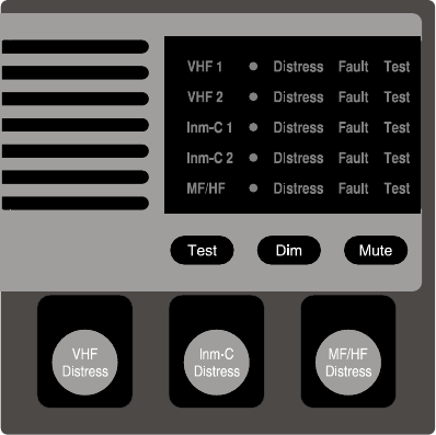
The Alarm Panel contains three main sections, intended for connection to System 5000 VHF,
System 5000 MF/HF equipment, and Inmarsat-C SES equipment. All sections work inde-
pendently and all control signals are galvanically isolated by opto-couplers.
For Inmarsat-C and VHF, the Alarm Panel has duplicated connections allowing two units of
each system to be supported simultaneously. Each section includes a push button for
distress alert initiation, and a distress annunciator for indication of distress alert transmission
in progress or distress or urgency calls received. Additionally there is an annunciator for
indication of equipment type. This is switched on when the appropriate transceiver has been
sensed by the Alarm Panel.
If a distress alarm is initiated on a system with duplicated units, only one of the units will
send the alarm. The selected unit is indicated on the display.
To protect against inadvertent activation the distress buttons are protected by spring loaded
transparent covers. A button must be kept pressed for 5 seconds before the distress alert is
initiated, during which time the audible alarm is beeping and the distress button is flashing.
The Alarm Panel is supplied from 24 V DC supply voltage (21 V to 32 V). The input is
reverse polarity protected.
4
0715
Technical Data
General
Illuminated red distress button with transparent cover for each section.
Indicator Alarm Panel with distress annunciator and status information for each connected
unit.
Audible alarm for indication of distress alert transmission in progress, or distress or urgency
calls received.
Dimmer push button for controlling light intensity in the indicator Alarm Panel.
Mute push button for resetting the audio alarm.
Test push button for verification of indicators, audible alarm and push buttons.
All distress functions work fully independent of each other.
All control signals are galvanically isolated by opto-couplers.
The indication line in the display goes off if the connection to the associated transceiver is
broken. When the connection is re-established it may take up to 20 seconds before it is
indicated in the display.
Supply Voltage: 24 V DC (21 V to 32 V)
Current consumption: max.100 mA
Operating temperature range: -20°C to +55°C
Compass safe distance: Standard: 0.9 m. Steering: 0.6 m.
5
0736
Operation
Distress
Sending Distress Alert
Open the key cover and press the ‘DISTRESS’ push button for minimum 5 seconds. The
alert button and the selection annunciator for the active unit flashes, and the buzzer sounds
periodically.
When the distress alert transmission starts, the distress button and the selection annunciator
change to a constant light. This indication is also given if a distress alert is initiated from the
transceiver.
When a distress acknowledgement has been received the distress annunciator flashes and
the buzzer sounds periodically - except Inmarsat-C equipment where distress button
changes to a slow cycle and the buzzer remains silent. Furthermore the dimmer will be set to
full light intensity.
When the distress acknowledgement has been read out or a distress/urgency alert has been
cancelled at the appropriate transceiver, the call lamp and buzzer on the Alarm Panel are
switched off.
Reception of Distress or Urgency Calls
Reception of Distress or Urgency calls, EGCs, and messages are indicated by a slowly
flashing distress annunciator and a periodic sound from the buzzer. Furthermore the dimmer
will be set to full light intensity.
6
0715
General
Test the Alarm Panel
Pressing and holding the Test button will make all light indicators and alarm buttons flash.
Pressing any other button while holding the Test button, will sound the buzzer enabling
verification of the buttons and the audible indicator.
Note that this only tests the Alarm Panel itself and does not involve the connected trans-
ceiver unit. For description of system test procedures, please refer to the User’s Manual of
each of the system.
Mute the alarm sound
If the buzzer is on, pressing the Mute button will mute the buzzer until reactivated by a new
event.
Adjust the light intensity
Pressing and holding the Dimmer button will increase or decrease the light intensity in the
display. To change between increasing and decreasing, release the button and press it
again. The light can be decreased to distinction, but it will always turn to full intensity if any
distress indicators turn on, or if the Test button is pressed.
40673
7
0736
Installation
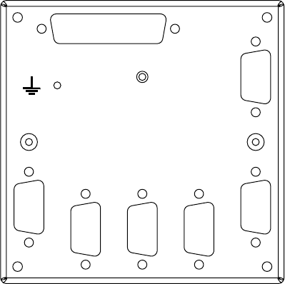
Connector overview
40708
Option
VHF 2
VHF 1 MF/HF
DC Supply
Inm-C 1
Inm-C 2
The Alarm Panel will connect to 5 transceiver units (2 × VHF, 2 × Inmarsat-C, and 1 × MF/
HF) each of which is provided a dedicated connector on the rear side of the Alarm Panel.
Auxiliary interfaces
The AP5065 Alarm Panel provides, through the option connector an auxiliary RS-422 line
with a separate Rx and Tx pair, that can be connected to external equipment for monitoring
of the Alarm Panel state. Unless specific installation instructions describes otherwise, this
interface should not be connected.
The power connector also provides a Service interface connection that may be used for
future maintenance of the Alarm Panel. Leave this disconnected for normal use.
8
0736
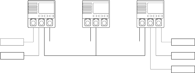
Interconnecting more Alarm Panels
40715
24V
24V
Interconnected panelsCable length < 200 meter
24V
24V
24V
24V
Inmarsat-C 1
VHF 1
Inmarsat-C 2
VHF 2
MF/HF
Alarm Panel 1 Alarm Panel 2 Alarm Panel 3
Up to 3 Alarm Panels can be interconnected and placed in different locations on the vessel.
Interconnected Alarm Panels maintain identical light and sound indications, so any operation
and behaviour on either Alarm Panel will be reflected on the others (except using the
Dimming button and the Test button – which only affects the single Alarm Panel being
dimmed or tested).
If interconnection is used, the combined set of Alarm Panels still only accepts the same 5
transceiver units, but each transceiver may be connected to either of the interconnected
Alarm Panels (e.g., the secondary VHF transceiver can be connected to the VHF 2 connec-
tor of any of the Alarm Panel).
The interconnection is physically established using a twisted pair cable. The interface is
electrically isolated and it must be supplied with 15V power to one of the Alarm Panels. The
15V interface power is taken from a dedicated supply available in the 9-pin power connector.
Note that only one of the interconnected Alarm Panels must supply the interface with power
in order to maintain the electrical isolation in the installation.
9
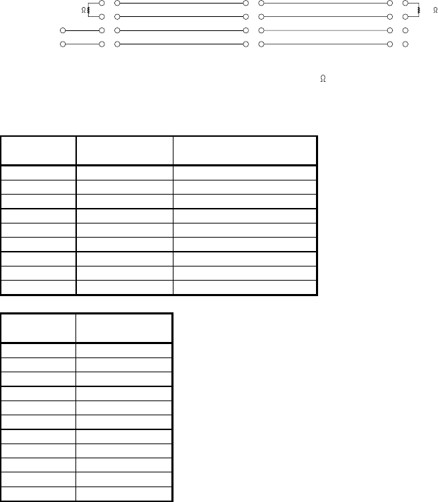
Wiring interconnected Alarm Panels
40714A
Alarm Panel 1 Alarm Panel 2 Alarm Panel 3
10
11
12
13
22
23
24
25
8
9
Option
DC Supply
Option Option
INTER S
INTER C
INTER H
INTER L
* 120
10
11
12
13
22
23
24
25
10
11
12
13
22
23
24
25
120
*
*
Note: The terminator resistor must match the cable used 120
is a typical value.
DC supply
D-sub 9 Designation
1ID-GND
2 S-RX SERVICE INTERFACE
3 S-TX SERVICE INTERFACE
4ID
5 GND SERVICE INTERFACE
6 DC- SUPPLY INPUT
7 DC+ SUPPLY INPUT
8 INTER-COUT INTERFACE SUPPLY OUT
9 INTER-SOUT INTERFACE SUPPLY OUT
Option
D-sub 25
1 and 14 AUX-TALKER B
2 and 15 AUX-TALKER A
3 and 16 AUX-TALKER C
5 and 18 AUX-LISTENER B
6 and 19 AUX-LISTENER A
7 and 20 AUX-LISTENER C
10 and 22 INTER L
11 and 23 INTER H
12 and 24 INTER C
13 and 25 INTER S
4.8.9 and 17 NC
Note: The cable shield must be connected only to the Alarm Panel that powers the
interface (Alarm Panel 1 in the wiring diagram). All segments of the interface cable
must have connected shields”
0736
10
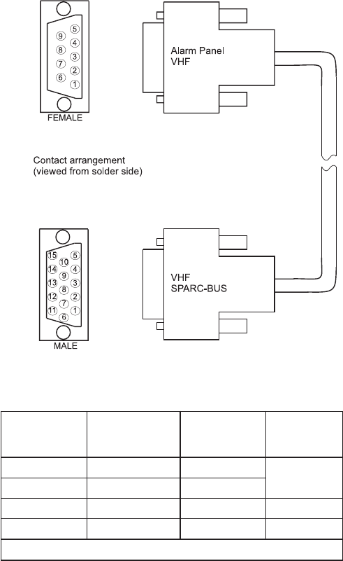
Wiring to VHF 1 or VHF 2
40712
lenaPmralA 3X'FHV' yaw9buS-D noitangiseD FHV SUB-CRAPS yaw51buS-D tnemmoC
3+SUB-CRAPS2
riapdetsiwT
5-SUB-CRAPS3
2DNG6
9V21+7
²mm5.0x2x2:epytelbaCm001.xaM:htgneL,deneercs
Note: The cable shield must be connected to chassis on the VHF equipment and must
be left unconnected at the Alarm Panel.”
0715
11
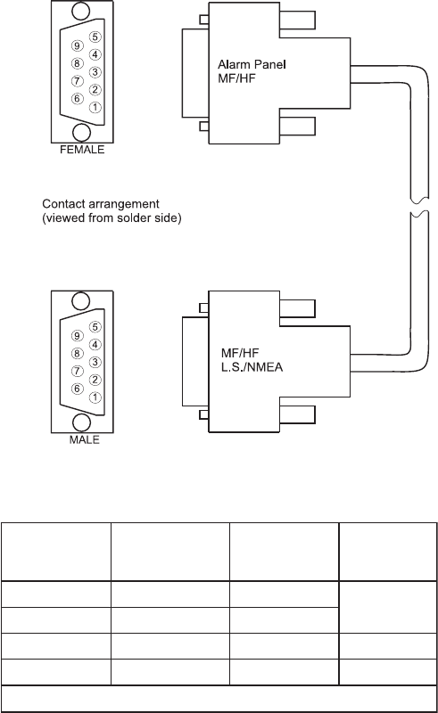
Wiring to MF/HF
40711
lenaPmralA 4X'FH/FM' yaw9buS-D noitangiseD FH/FM XUA yaw9buS-D tnemmoC
3+SUB-CRAPS1
riapdetsiwT
5-SUB-CRAPS6
2DNG5
9V42+7
²mm5.0x2x2:epytelbaCm001.xaM:htgneL,deneercs
Note: The cable shield must be connected to chassis on the MF/HF equipment and
must be left unconnected at the Alarm Panel.”
0736
12
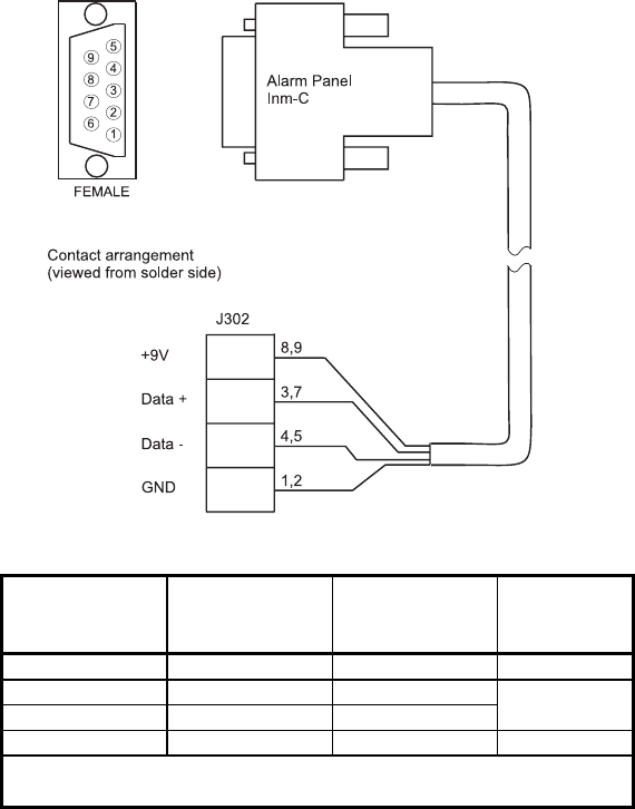
Wiring to Inmarsat-C 1 or Inmarsat-C 2 (mini-C)
40710
Alarm Panel mini-C
Inm-C Designation Comment
D-sub 9 way J302
1,2 GND GND
3,7 Data + Data +
4,5 Data - Data -
8,9 VCC IN +9V
Cable type: min. 2 x 2 x 0.2mm2 screened.
Length: Max 250m
Twisted pair
Note 1: The cable shield must be connected to chassis on the Inmarsat-C equipment and
must be left disconnected at the Alarm Panel.”
Note 2: If the cable ends at the Alarm Panel, then connect a strap between pin 6 and 7 in
order to activate an internal termination resistor.
Note 3: For further details refer to TT-3000E mini-C GMDSS system Installation manual
(Doc. TT98-122414)
Note 4: Connection of a classic Inmarsat-C transceiver (TT-3020C) to the Alarm Panel
requires interface TT-3687A installed. For details refer to TT-3687A Alarm Panel
adapter Installation & User manual (Doc. TT98-125903)
0736
13
0736
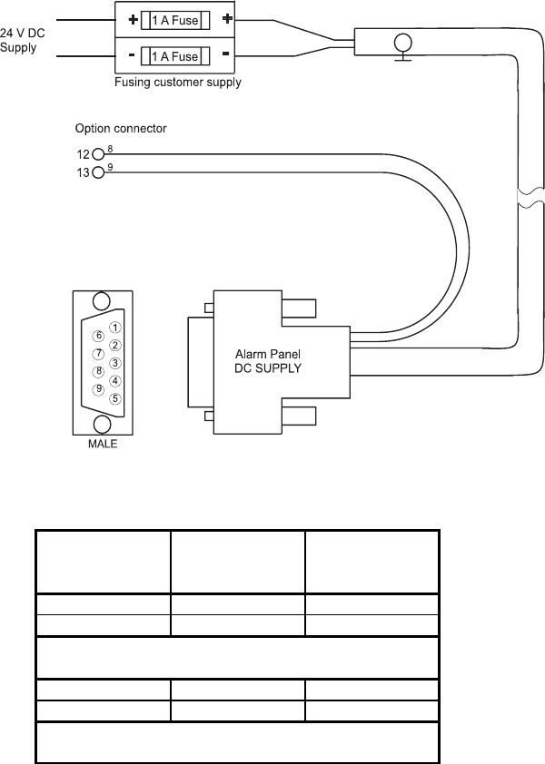
Wiring to 24V DC Supply
40716A
Alarm Panel Alarm Panel
DC Supply Designation Option
D-sub 9 way Connector
6 DC -
7DC +
8 INTER-COUT 12 (Note)
9 INTER-SOUT 13 (Note)
Cable type: 2 x 0.5mm2 screened.
Length: Max. 100m
Wiring: 2 x 0.2mm2.
Length: 0.15 - 0.2m
Note:
Interface supply used only if interconnecting 2 or 3 alarm panels - refer to page 8.
14
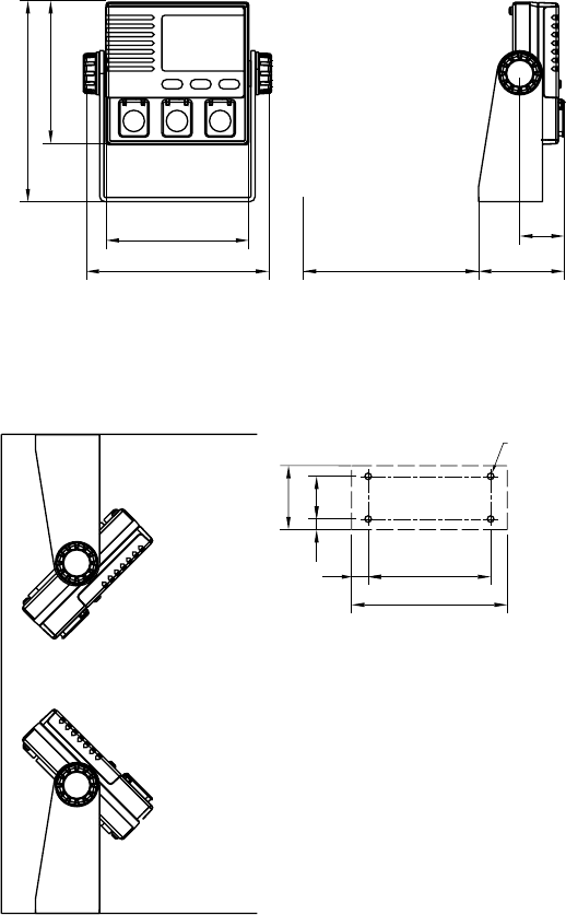
Outline and dimension
40674A
100
128
100
141
60.5
31.5
Space for cable entry
min. 150
Mounting option Drilling plan
40722
86
30
109.2
45
7.5
11.6
Tilting
±
45
°
4 x ø 4.5
Dimensions are in mm.
Weight:
AP5065 0.8 Kg
0736
15
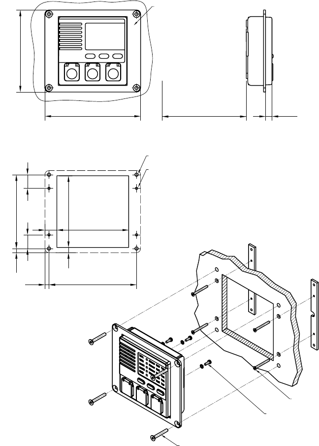
Alarm panel with mounting bracket
40723B
140
120
Panel mounting kit (Option)
Part no 405065A-920
9.6
Space for cable entry
min. 150
Drilling plan
105
105
6
108
128
6
4 x ø5
17.5
7.5
4 x ø3.5 uns for M3 ISO 14581
20 20
4 pcs M4x30
4 pcs M3x30
3 pcs M3x8
Cut out
Drilling plan
0736
16

Thrane & Thrane A/S • info@thrane.com • www.thrane.com
TT-98-125065-THR-C Issue: 0736