Thrane and Thrane A S TU5160 Sailor System 5000 150W GMDSS MF/HF SSB DSC NBDP User Manual M1252BGB0 0 p65
Thrane & Thrane A/S Sailor System 5000 150W GMDSS MF/HF SSB DSC NBDP M1252BGB0 0 p65
Contents
user manual 4

S.P. RADIO A/S
AALBORG
DENMARK
TECHNICAL MANUAL
FOR
H1252B DC PRINTER

Please note
Any responsibility or liability for loss or damage in connection with the use of this product and the
accompanying documentation is disclaimed.
The information in this manual is furnished for informational use only, is subject to change without
notice, may contain errors or inaccuracies, and represents no commitment whatsoever.
This agreement is governed by the laws of Denmark.
Doc. no.: M1252BGB Issue: A/0146
CONTENTS PART I
1 GENERAL INFORMATION 1-1
1.1 OKI DOCUMENTATION 1-1
2 INSTALLATION 2-1
2.1 MOUNTING POSSIBILITIES, DIMENSIONS AND DRILLING PLAN 2-1
2.2 H1252B PRINTER WITH MOUNTING KIT H1250 OR GMDSS
CONSOLE H2192 2-2
3 PARTS LIST 3-1
CONTENTS PART II
1 GENERAL INFORMATION 1-1
1.1 INTRODUCTION 1-1
1.2 PRINCIPLE OF OPERATION 1-1
1.3 TECHNICAL DATA 1-1
2 MAINTENANCE/MODIFICATION 2-1
2.1 DISASSEMBLING TO REMOVE THE MAINS TRANSFORMER 2-1
2.2 DISASSEMBLING AND MOUNTING OF THE ON-OFF SWITCH 2-1
2.3 MOUNTING THE DC POWER SUPPLY AND REASSEMBLING 2-2
2.4 ELECTRICAL CONNECTIONS 2-4
3 SERVICE 3-1
3.1 PRINTER SELFTEST 3-1
3.2 MODULE CHECK OF THE DC POWER SUPPLY 3-1
3.3 CHECK AFTER REPAIR 3-1
4 MECHANICAL DISASSEMBLING OF PRINTER 4-1
5 CIRCUIT DESCRIPTION 5-1
5.1 DC POWER SUPPLY 5-1
6 PARTS LIST 6-1
H1252B
9737
CONTENTS
1 GENERAL INFORMATION 1-1
1.1 OKI DOCUMENTATION 1-1
PART I/H1252B
PAGE 1-1
1 GENERAL INFORMATION
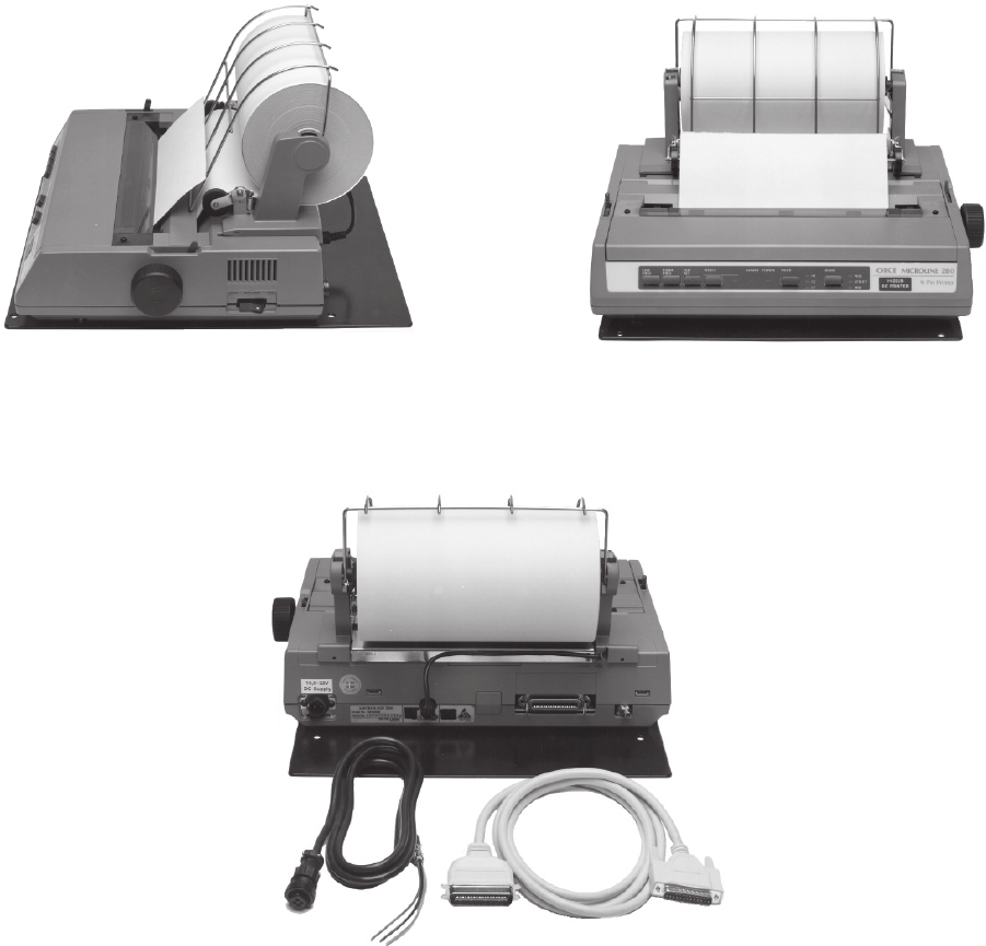
H1252B Hardcopy printer is an OKI MICROLINE 182/280 printer with built-in DC power supply for 10.5-
32V DC operation. H1252B is as standard delivered with a Roll Paper Stand, other paper types can also
be used, please refer to the OKI manual for detailed information.
H1252B is as standard delivered with the mounting kit H1250, it can also be mounted on the H2192
GMDSS Console using the mounting plate which is delivered together with the H2192 GMDSS Console.
Paper roll, Power cable and Centronics cable are supplied with the H1252B.
501279 501274
1.1 OKI DOCUMENTATION
PART I/H1252B
501278
CONTENTS
2 INSTALLATION 2-1
2.1 MOUNTING POSSIBILITIES, DIMENSIONS AND DRILLING PLAN 2-1
2.2 H1252B PRINTER WITH MOUNTING KIT H1250 OR GMDSS
CONSOLE H2192 2-2
PART I/H1252B
PAGE 2-1
2 INSTALLATION
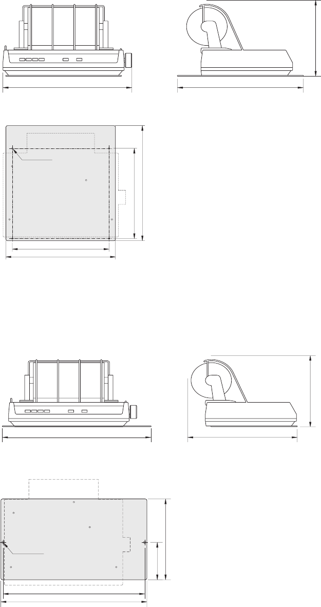
2.1 MOUNTING POSSIBILITIES, DIMENSIONS AND DRILLING PLAN
Mounting kit H1250
240 mm
280 mm 371 mm
28709
28711
4 pcs ø6 mm
300 mm
341 mm
371 mm
290 mm
Mounting kit H2192
442 mm 325 mm
240 mm
28699
428 mm
442 mm
2 pcs 4 mm
28710
118.5 mm
256 mm
PART I/H1252B
2 INSTALLATION PART I/H1252B
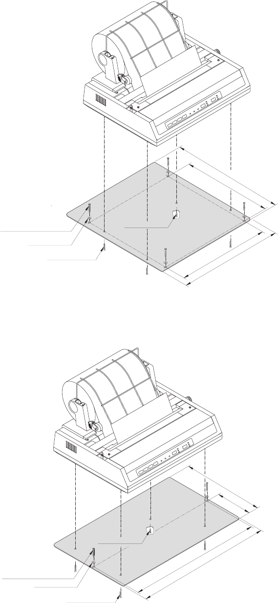
2.2 H1252B PRINTER WITH MOUNTING KIT H1250 OR GMDSS
CONSOLE H2192
H1252B printer with H1250
PAGE 2-2
H1252B printer with H2192
28697
Screw, 1 piece M4 x 10
Washers, 2 pieces M4
Self-cutting screws, 2 pieces 4.2 x 25
Screws, 3 pieces M4 x 20
428 mm
442 mm
118.5 mm
256 mm
28641
Self-cutting screws, 4 pieces 4.2 x 25
Screws, 3 pieces M4 x 20
Washers, 4 pieces M4
Screw, 1 piece M4 x 10
300 mm
341 mm
290 mm
371 mm
CONTENTS
3 PARTS LIST 3-1
PART I/H1252B

PAGE 6-1
3 PARTS LIST
PART I/H1252B
OKI MICROLINE u182/280 WITH 24V DC POWER SUPPLY ECI A/S 821252
POSITION DESCRIPTION MANUFACTOR TYPE PART NO.
VARIOUS BOTTOM PLATE PRINTER 182 H1250 ECI A/S 1-0-24747 / 140.956 200606
VARIOUS TELEX ROLL B=20.9cm L=120m SINGLE LAYER NCR Art.Nr: 230.100 47.830
VARIOUS INTERCONNECTION CABLE 25 POLES SUB D-CENTRONIC RADIO PARTS Art.Nr: 393535 56.013
VARIOUS POWER CABLE 3 POLE H1252B 2000mm (T&T M061-101028) MONTRONICS 3-0-28478 56.066
Art.Nr: M024
VARIOUS SCREW KIT ECI A/S 700654 700654
VARIOUS SPARE FUSES FOR H1252B H1252B ECI A/S 0-0-27246 727246
VARIOUS 10.5-32V DC POWER SUPPLY FOR OKI PRINTER u182/u280 ECI A/S 0-0-28515 728515
VARIOUS MANUAL FOR H1252B ENGLISH ECI A/S M1252BGB
CONTENTS
1 GENERAL INFORMATION 1-1
1.1 INTRODUCTION 1-1
1.2 PRINCIPLE OF OPERATION 1-1
1.3 TECHNICAL DATA 1-1
PART II/H1252B
PART II/H1252B
PAGE 1-1
1 GENERAL INFORMATION
1.1 INTRODUCTION
This section gives you all the necessary informations to maintaine the DC power supply module. It also
specify how to modify the printer to operate on DC supply instead of AC supply.
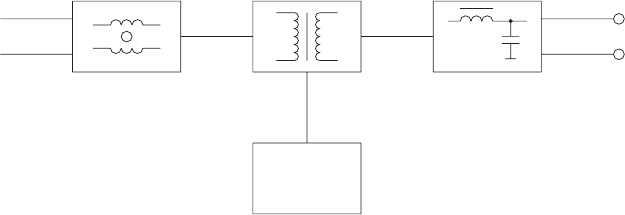
1.2 PRINCIPLE OF OPERATION
The power supply module is constructed to operate from a battery voltage of 10.5V DC to 32V DC to
deliver the necessary voltages for the printer. The voltage conversion takes place in a “flyback” switch
converter, which is controlled by a current mode controller. The regulation of the output voltage is
controlled via a separate winding of the transformer, which also deliveres the power for the control circuit.
At the input and at the output are placed filters to suppress the switch noise.
BLOCKDIAGRAM
PWM
INPUT
FILTER CONVERTER
SWITCH FILTER
OUTPUT
CONTROL
CIRCUIT
+
-
10.5V....32V +30V
+10V
28480
1.3 TECHNICAL DATA
Input voltage range : 10.5V DC to 32V DC
Current consumption : max. 4.5A (fuse = 6.3AT)
Output voltages : 10V DC / 0.3A
: 30V DC / 0.8A
Noise from input terminals : better than CEPT Rec. T/R 34-01
On/off : by switch
Operating temperature : -15o C to +55o C
CONTENTS
2 MAINTENANCE/MODIFICATION 2-1
2.1 DISASSEMBLING TO REMOVE THE MAINS TRANSFORMER 2-1
2.2 DISASSEMBLING AND MOUNTING OF THE ON-OFF SWITCH 2-1
2.3 MOUNTING THE DC POWER SUPPLY AND REASSEMBLING 2-2
2.3.1 MOUNTING OF THE DC POWER SUPPLY 2-2
2.3.2 MODIFICATION OF THE PRINTER MAIN CONTROL BOARD 2-3
2.3.3 REASSEMBLING OF THE PRINTER 2-3
2.4 ELECTRICAL CONNECTIONS 2-4
PART II/H1252B
PAGE 2-1
2 MAINTENANCE/MODIFICATION
This section is intended for use when modifying the printer to operate from DC supply instead of 220V
AC supply.
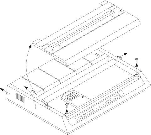
2.1 DISASSEMBLING TO REMOVE THE MAINS TRANSFORMER
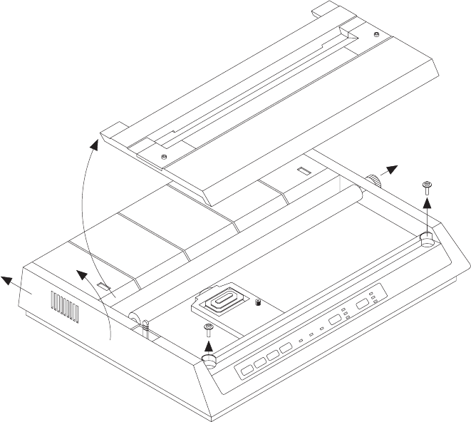
Remove the access cover by lifting up rear edge.
Pull out the platen knob.
Remove the two screws.
Remove the top cover by lifting up the front and pushing it backward.
Remove the transformer output cable from the printer Main Control Board.
Remove the ground strap screw, but keep it for later use.
Remove the two screws, that fix the transformer, but keep them for later use.
Remove the transformer assembly with power PCB and AC cord receptable by lifting upwards.
Remove the 220V~ label located at the panel cut out for the AC cord receptable.
2
45
3
3
28560
1
2.2 DISASSEMBLING AND MOUNTING OF THE ON-OFF SWITCH
It is necessary to remove the ON-OFF switch from the transformer assembly to use it again on the DC
power supply module.
Remove the filter and switch board from the transformer by pulling it off.
Unsolder the ON-OFF Switch.
Solder the switch to the two loose wires on the DC power supply module. Then twist the wires to the switch
to suppress noise.
PART II/H1252B
MAINTENANCE/MODIFICATION PART II/H1252B
PAGE 2-2
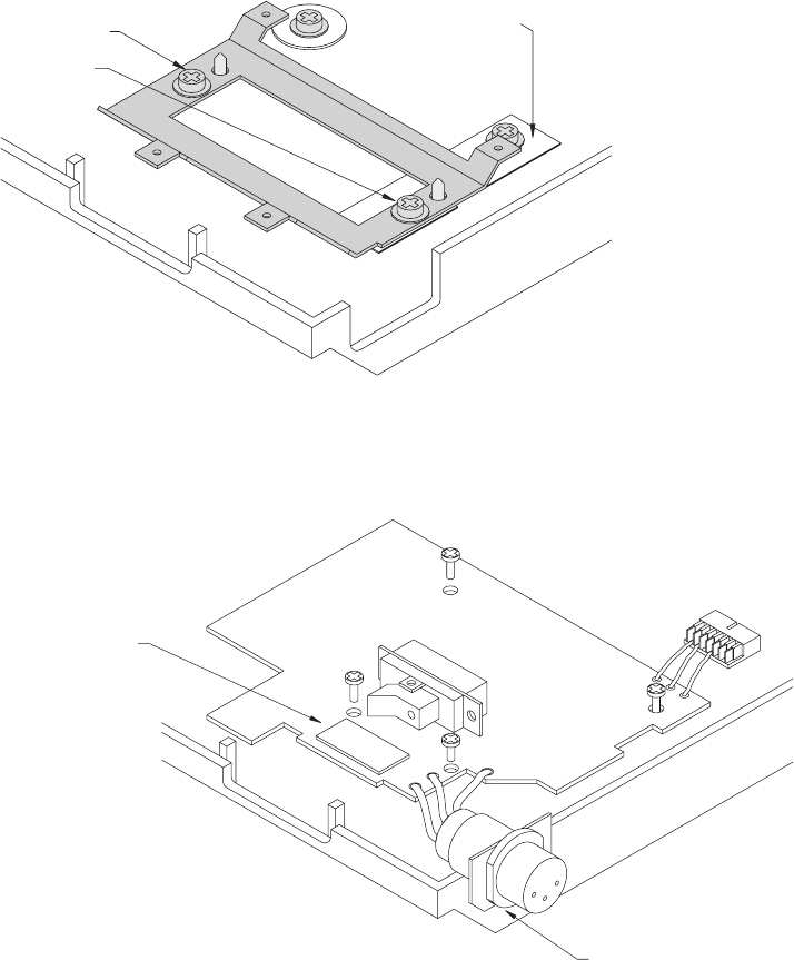
2.3 MOUNTING THE DC POWER SUPPLY AND REASSEMBLING
Remove the cover on the glue pad and when the power supply module is placed properly, the switch is
placed in the slots in the cabinet and is pressed down to the glue pad.
The mounting frame is
fixed with the two
screws from the
mains transformer
Ground connection is
mounted under the
mounting frame
28556
28557
Note: Remove the
" 220V ~ " label
The ON-OFF Switch is placed
in the printer panel cutout and
fixed to the PCB with a glue pad
DC power supply circuit board is fixed
to the mounting frame with four screws
2.3.1 MOUNTING OF THE DC POWER SUPPLY
Place the ground connection over the rear transformer hole, and fix it with the ground screw.
Place the mounting frame where the transformer was mounted, and fix it with the two screws from the
transformer.
Then place the DC power supply module on the mounting frame, and fix it with four screws.
Be sure the power ON-OFF switch is correctly placed in the panel cut out slot.
Press the plate with the DC input connector in to the panel cut out the formen AC cord receptable.
Connect the output cable to the printer Main Control Board.
MAINTENANCE/MODIFICATION PART II/H1252B
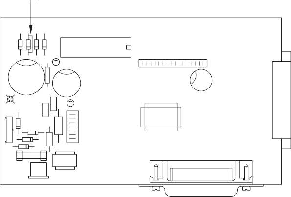
2.3.2 MODIFICATION OF THE PRINTER MAIN CONTROL BOARD
If the printer is equipt with a DC power supply module of other type than from ECI, it is necessary to
modify the printer main board. As seen below, the diode D28 (D10) on the printer main board is short
circuited.
If the printer is equipt with a DC power supply module from ECI, module no. 628471 it is not
recommended to short circuit the diode D28 (D10) on the printer main board.
Run the printer selftest programme.
Switch on the ON-OFF switch and simultaneously press down the “line feed” button.
After a few seconds (at low input voltage) the printer starts the selftest printing routine, which means
that the DC power supply is OK.
Switch off the printer.
D28
(D10)
Main Control Board
28479
2.3.3 REASSEMBLING OF THE PRINTER
Place the top cover by lifting the front end and place holes in the rear end into the two small hooks in
the bottom cabinet.
To reassemble the printer, do the reverse procedure of the disassembling.
Then run the selftest programme of the printer. (See above)
PAGE 2-3
MAINTENANCE/MODIFICATION PART II/H1252B
PAGE 2-4
2.4 ELECTRICAL CONNECTIONS
28558
RED
GREEN
BLACK
YELLOW/GREEN
BLACK
RED
ON-OFF SWITCH
FROM MAINS
DC INPUT CABLE
OUTPUT CABLE
TRANSFORMER
CONTENTS
3 SERVICE 3-1
3.1 PRINTER SELFTEST 3-1
3.2 MODULE CHECK OF THE DC POWER SUPPLY 3-1
3.3 CHECK AFTER REPAIR 3-1
PART II/H1252B
PAGE 3-1
PART II/H1252B
3 SERVICE
3.1 PRINTER SELFTEST
To do a performance test of the DC power supply, a selftest programme in the printer can be used.
Connect a DC power source of 10.5V to 32V to the DC input connector.
Switch on the ON-OFF switch and simultaneously press down the “line feed” button.
After a few seconds (at low input voltage) the printer starts the selftest a printing routine, which means
that the power supply is OK.
Switch off the printer.
3.2 MODULE CHECK OF THE DC POWER SUPPLY
Connect a dummy load of 33W/30W to 30V output.
Connect a dummy load of 33W/5W to 10V output.
Connect a DC power source of 10.5V to the DC input connector.
Switch on the power supply module. The module has to start up within 4 seconds.
Connect a voltmeter to the 30V output and read 28 ±2V.
Connect a voltmeter to the 10V output and read 9V ±1V.
Connect a DC power source of 32V to the DC input connector.
Switch on the power supply module. The module has to start up within 1 second.
Connect a voltmeter to the 30V output and read 33V ±2V.
Connect a voltmeter to the 10V output and read 10V ±1V.
Disconnect the dummy load from the 30V output and read the voltage to 39V ±2V.
3.3 CHECK AFTER REPAIR
If any repair has occurred to the power supply module, then perform chapter 3.2 MODULE CHECK OF
THE DC POWER SUPPLY.
CONTENTS
4 MECHANICAL DISASSEMBLING OF PRINTER 4-1
PART II/H1252B
PART II/H1252B
PAGE 4-1
4 MECHANICAL DISASSEMBLING OF PRINTER
2
45
3
3
28560
1
CONTENTS
5 CIRCUIT DESCRIPTION 5-1
5.1 DC POWER SUPPLY 5-1
PART II/H1252B
PAGE 5-1
5 CIRCUIT DESCRIPTION
5.1 DC POWER SUPPLY
To suppress noise on the supply wires a filter is build around the current compensated choke L1.
Furthermore the RC snubbers across the transformer prevent unwanted oscillations during transition
time. The diode D7 in conjunction with R16 and C19 clamps the transient voltage spikes across the
switch transistor Q1.
When the supply is switched on, the capacitor C6 is charged by means of R1 and when the voltage
exceeds approx. 8.7V the controller U1 turns on. After a few cycles power is delivered from the
bootstrap winding of the transformer to maintain the supply to the controller U1. When switching of the
supply voltage, the power from the transformer disappears. This means the supply voltage to U1
decreases to approx. 7.6V and the controller U1 switches off.
The rectified voltage from the bootstrap winding is also used to regulate the output voltages, which
mainly is determined by R8 and R11. The feedback voltage is led to U1 pin 2. The resistors R10 and
R9 and the capacitor C17 form the compensating circuit for the voltage regulation.
The controller is working at a fixed frequency of approx. 100 kHz, determined by R7 and C16.
The switch current is sensed by R15 and led to U1 pin 3 after being filtered by R14 and C18. The current
sense voltage is a ramp voltage, which is compared to a DC level determined by the voltage regulation
circuit. When the ramp exceeds the DC level, the controller U1 switch off the FET Q1. This current
sense circuit forms a current regulation loop, which is stabilizing the over all regulation and prevents
high current to damage the switch transistor Q1.
When Q1 is on, the output diodes D3 and D4 is reversed biased and current to the load is delivered from
the capacitors C12 and C13. During the off time of Q1, the transformer outputs deliver the currents to
the capacitors C12 and C13 and to the load.
The chokes L2 and L3 are parts of lowpass filters to suppress voltage spikes.
Because of the converter principle , which is a ringing choke flyback type, without direct feedback from
the output the voltages, the output voltages are load dependent.
At input voltage under approx. 15V and at full load, the converter "changes frequency" and gets an
irregular duty-cycle. That is normal behaviour.
At low input voltage the start up time can be as long as 4 seconds, depending on the load.
PART II/H1252B
CIRCUIT DESCRIPTION PART II/H1252B
PAGE 5-2 9505
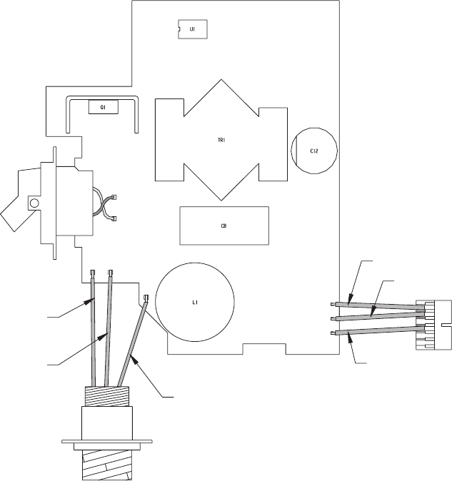
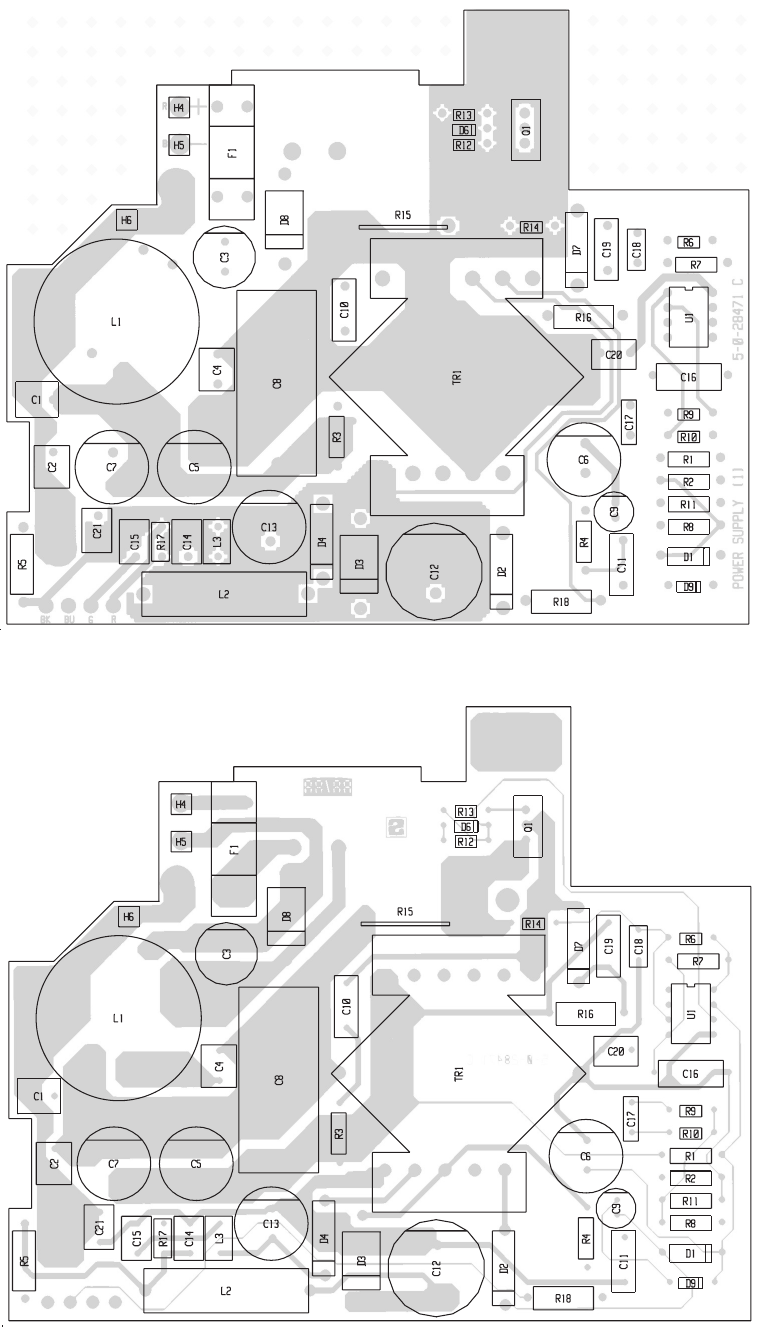
COMPONENT LOCATION DC POWER SUPPLY
View from component side with upper side tracks.
View from component side with lower side tracks.
PCB rev. 28471C
5 CIRCUIT DESCRIPTION PART II/H1252B
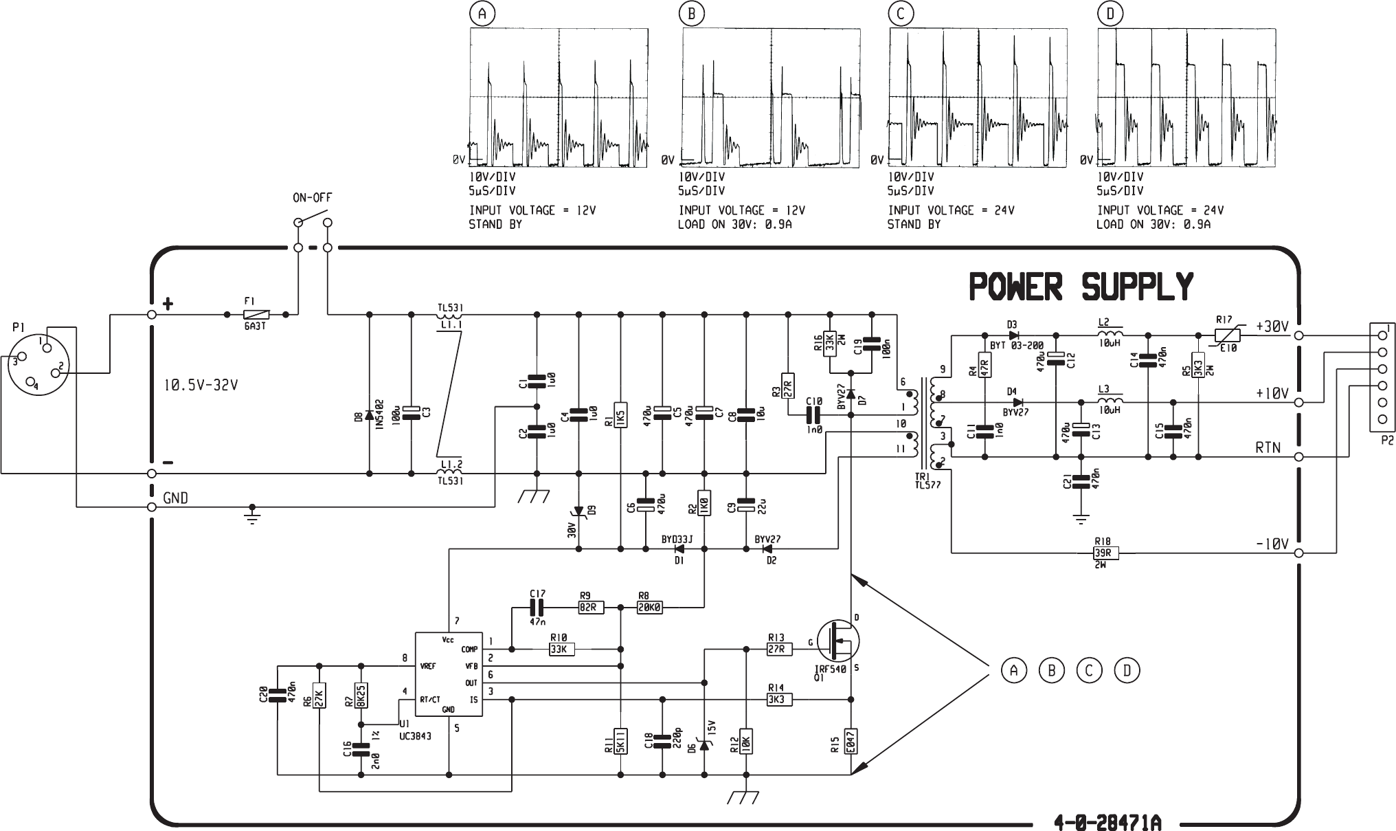
SCHEMATIC DIAGRAM DC POWER SUPPLY
PAGE 5-3
This diagram is valid for PCB rev.28471C
9505
CONTENTS
6 PARTS LIST 6-1
PART II/H1252B

PAGE 6-1
6 PARTS LIST
PART II/H1252B
10.5-32V DC POWER SUPPLY FOR OKI PRINTER u182/u280 ECI A/S 0-0-28515 728515
POSITION DESCRIPTION MANUFACTOR TYPE PART NO.
VARIOUS GROUND CONNECTION FOR DC POWER SUPPLY H1252B ECI A/S 1-0-28529 228259
VARIOUS MOUNTING FRAME FOR PCB H1252B ECI A/S 1-0-28473 228473
VARIOUS POWER CABLE 3 POLE 3x0.75 2000mm (T&T M061-101028) MONTRONICS 3-0-28478 56.066
Art.Nr: M024-56.066
VARIOUS SCREW M3x4mm WULCAN HFC 9041 M3x4 PHJX-Z 86.951
DIN 7985
-1 POWER SUPPLY FOR PRINTER (MODULE 1) H1252B ECI A/S 5-0-28471C / 4-0-28471A 628471
POWER SUPPLY FOR PRINTER (MODULE 1) H1252B ECI A/S 5-0-28471C / 4-0-28471A 628471
POSITION DESCRIPTION MANUFACTOR TYPE PART NO.
C1 CAPACITOR MKT 1uF 10% 63VDC ERO MKT 1826-510/06 5-G 11.137
C2 CAPACITOR MKT 1uF 10% 63VDC ERO MKT 1826-510/06 5-G 11.137
C3 CAPACITOR ELECTROLYTIC 100uF -20/+50% 63VDC ELNA RJ2-63-V-101-M-F 14.620
C4 CAPACITOR MKT 1uF 10% 63VDC ERO MKT 1826-510/06 5-G 11.137
C5 CAPACITOR ELECTROLYTIC 470uF -20/+50% 40VDC ELNA RJ3-50-471-M-F 14.649
C6 CAPACITOR ELECTROLYTIC 470uF -20/+50% 40VDC ELNA RJ3-50-471-M-F 14.649
C7 CAPACITOR ELECTROLYTIC 470uF -20/+50% 40VDC ELNA RJ3-50-471-M-F 14.649
C8 CAPACITOR MKT 10uF 10% 63VDC ERO MKT 1822-610/06 5 11.086
C9 CAPACITOR ELECTROLYTIC 22uF 20% 35VDC ELNA RJ2-35-V-220-M-F1 14.516
C10 CAPACITOR MKT 1000pF 10% 400VDC ERO MKT 1818-210/63 5-G 11.139
C11 CAPACITOR MKT 1000pF 10% 400VDC ERO MKT 1818-210/63 5-G 11.139
C12 CAPACITOR ELECTROLYTIC 470uF -20/+30% 63VDC PHILIPS 2222 035 68471 14.604
C13 CAPACITOR ELECTROLYTIC 470uF -20/+50% 40VDC ELNA RJ3-50-471-M-F 14.649
C14 CAPACITOR MKT 470nF 20% 63VDC ERO MKT 1826-447/06 6-G 11.188
C15 CAPACITOR MKT 470nF 20% 63VDC ERO MKT 1826-447/06 6-G 11.188
C16 CAPACITOR POLYSTYRENE 2nF 1% 160V PHILIPS 2222 429 82002 10.283
C17 CAPACITOR MKT 47nF 5% 63VDC PHILIPS 2222 370 79473 11.156
C18 CAPACITOR CERAMIC 220pF 2% N750 100VDC PHILIPS 2222 683 58221 16.075
C19 CAPACITOR MKT 100nF 10% 100VDC ERO MKT 1818-410/01 5-G 11.180
C20 CAPACITOR MKT 470nF 20% 63VDC ERO MKT 1826-447/06 6-G 11.188
C21 CAPACITOR MKT 470nF 20% 63VDC ERO MKT 1826-447/06 6-G 11.188
D1 DIODE FAST RECOVERY 600VDC/1A PHILIPS BYD 33 J 27.150
D2 DIODE V.F.R. 100VDC 2A(AV) BYV27-100 PHILIPS BYV27-100 27.114
D3 DIODE FAST RECOVERY 200V/3A BYT03-200/MUR420 THOMSON BYT 03-200 TAPED 25.210
D4 DIODE V.F.R. 100VDC 2A(AV) BYV27-100 PHILIPS BYV27-100 27.114
D6 DIODE ZENER 15V 5% 0.4W BZX79C15 PHILIPS BZX79C15 26.561
D7 DIODE V.F.R. 100VDC 2A(AV) BYV27-100 PHILIPS BYV27-100 27.114
D8 DIODE RECTIFIER 1N5402 200V/3A PROMAX 1N5402 25.116
D9 DIODE ZENER 30V 5% 0.4W BZX79C30 PHILIPS BZX79C30 26.578
F1 FUSE 5x20mm 6A3 T 250V ELU 17912006300 45.510
L1 CHOKE TL531 TRANS-ELECTRO 6-0-26309A 400531
L2 CHOKE FIXED 10uH 20% 6Amp SIEMENS B82133-A5302-M 20.290
L3 CHOKE FIXED 10uH 5% NEOSID 00 6122 00 20.118
Q1 TRANS.POW.MOSFET N-CHANN. 100V/27A/85mOHM IRF540 MOTOROLA IRF540 29.402
R1 RESISTOR MF 1k5 OHM 5% 0.4W PHILIPS 2322 181 53152 01.204
R2 RESISTOR MF 1k0 OHM 5% 0.4W PHILIPS 2322 181 53102 01.200
R3 RESISTOR MF 27 OHM 5% 0.4W PHILIPS 2322 181 53279 01.160
R4 RESISTOR MF 47 OHM 5% 0.4W PHILIPS 2322 181 53479 01.166
R5 RESISTOR PMF 3k3 OHM 5% 2W PHILIPS 2322 194 13332 04.209
R6 RESISTOR MF 27k OHM 5% 0.33W PHILIPS 2322 187 73273 02.506
R7 RESISTOR MF 8k25 OHM 1% 0.6W PHILIPS 2322 156 18252 03.423
R8 RESISTOR MF 20k0 OHM 1% 0.6W PHILIPS 2322 156 12003 03.452
R9 RESISTOR MF 82 OHM 5% 0.33W PHILIPS 2322 187 73829 02.446
R10 RESISTOR MF 33k OHM 5% 0.33W PHILIPS 2322 187 73333 02.508
R11 RESISTOR MF 5k11 OHM 1% 0.6W PHILIPS 2322 156 15112 03.414
R12 RESISTOR MF 10k OHM 5% 0.33W PHILIPS 2322 187 73103 02.496
R13 RESISTOR MF 27 OHM 5% 0.33W PHILIPS 2322 187 73279 02.434
R14 RESISTOR MF 3k3 OHM 5% 0.33W PHILIPS 2322 187 73332 02.484
R15 RESISTOR 47m OHM 5% 0.6W MODULOHM I/S 98247/47U-J-MI-A-1 06.233
R16 RESISTOR PMF 33k OHM 5% 2W PHILIPS 2322 194 13333 04.229
R17 RESISTOR PTC 100m OHM 0.7W BOURNS MF-R110 07.162
R18 RESISTOR PMF 39 OHM 5% 2W PHILIPS 2322 191 33909 04.145
TR1 SMPS TRAFO FOR PRINTER H1 TL577 ECI A/S 6-0-28472B 400577
U1 PWM CONTROLLER CURRENT MODE, UC3843 TEXAS UC3843P (UC2843P) 31.177
9505